NASA/CR–2011-217153
Hardware Specific Integration Strategy for Impedance-Based Structural Health Monitoring of Aerospace Systems Robert B. Owen Extreme Diagnostics, Inc., Boulder, Colorado Andrew L. Gyekenyesi Ohio Aerospace Institute, Cleveland, Ohio Daniel J. Inman and Dong S. Ha Virginia Polytechnic Institute and State University, Blacksburg, Virginia
May 2011
NASA STI Program . . . in Profile
Since its founding, NASA has been dedicated to the advancement of aeronautics and space science. The NASA scientific and technical information (STI) program plays a key part in helping NASA maintain this important role. The NASA STI program operates under the auspices of the Agency Chief Information Officer. It collects, organizes, provides for archiving, and disseminates NASA’s STI. The NASA STI program provides access to the NASA Aeronautics and Space Database and its public interface, the NASA Technical Report Server, thus providing one of the largest collections of aeronautical and space science STI in the world. Results are published in both non-NASA channels and by NASA in the NASA STI Report Series, which includes the following report types: x
x
x
TECHNICAL PUBLICATION. Reports of completed research or a major significant phase of research that present the results of NASA programs and include extensive data or theoretical analysis. Includes compilations of significant scientific and technical data and information deemed to be of continuing reference value. NASA counterpart of peerreviewed formal professional papers, but having less stringent limitations on manuscript length and extent of graphic presentations. TECHNICAL MEMORANDUM. Scientific and technical findings that are preliminary or of specialized interest, e.g., quick release reports, working papers, and bibliographies that contain minimal annotation. Does not contain extensive analysis. CONTRACTOR REPORT. Scientific and technical findings by NASA-sponsored contractors and grantees.
x
CONFERENCE PUBLICATION. Collected papers from scientific and technical conferences, symposia, seminars, or other meetings sponsored or co-sponsored by NASA.
x
SPECIAL PUBLICATION. Scientific, technical, or historical information from NASA programs, projects, and missions, often concerned with subjects having substantial public interest.
x
TECHNICAL TRANSLATION. Englishlanguage translations of foreign scientific and technical material pertinent to NASA’s mission.
Specialized services also include creating custom thesauri, building customized databases, and organizing and publishing research results. For more information about the NASA STI program, see the following: x
Access the NASA STI program home page at http://www.sti.nasa.gov
x
E-mail your question via the Internet to
[email protected]
x
Fax your question to the NASA STI Help Desk at 443-757-5803
x
Phone the NASA STI Help Desk at 443-757-5802
x
Write to: NASA STI Help Desk NASA Center for AeroSpace Information 7115 Standard Drive Hanover, MD 21076-1320
NASA/CR–2011-217153
Hardware Specific Integration Strategy for Impedance-Based Structural Health Monitoring of Aerospace Systems Robert B. Owen Extreme Diagnostics, Inc., Boulder, Colorado Andrew L. Gyekenyesi Ohio Aerospace Institute, Cleveland, Ohio Daniel J. Inman and Dong S. Ha Virginia Polytechnic Institute and State University, Blacksburg, Virginia
National Aeronautics and Space Administration Langley Research Center Hampton, Virginia 23681-2199
May 2011
The use of trademarks or names of manufacturers in this report is for accurate reporting and does not constitute an official endorsement, either expressed or implied, of such products or manufacturers by the National Aeronautics and Space Administration.
Available from: NASA Center for AeroSpace Information 7115 Standard Drive Hanover, MD 21076-1320 443-757-5802
Table of Contents Introduction and Overview ............................................................................................................................................ 1 2 Significance of SHM and Some Current Technology ................................................................................................ 1 2.1 Practical Implementation of SHM ....................................................................................................................... 1 2.2 Relevance and Significance of SHM ................................................................................................................... 2 2.3 Impedance-based Structural Health Monitoring .................................................................................................. 2 2.3.1 Advantages and Characteristics of the Impedance Method .......................................................................... 3 2.4 Energy Harvesting ............................................................................................................................................... 4 2.5 SAFE Innovation Relative to Current Status and Feasibility............................................................................... 4 2.5.1 State of the General SHM Market ................................................................................................................ 4 2.5.2 State of the SHM Art .................................................................................................................................... 4 2.5.3 SAFE Feasibility ........................................................................................................................................... 5 3 Existing SAFE Prototype and Related Work .............................................................................................................. 5 3.1 Existing SAFE Prototype..................................................................................................................................... 5 3.2 Integration with Wave Propagation ................................................................................................................. 6 4 Chip Design, Development and Verification Background ......................................................................................... 7 4.1 General Background ............................................................................................................................................ 7 4.2 SAFE Chip Development Objectives, Goals and Tasks .................................................................................... 10 4.2.1 Chip Development—incorporation of SHM operational tools ................................................................... 11 4.2.2 Chip Development—SHM tools hardware implementation ....................................................................... 11 4.2.3 Chip Development—PCB level prototyping .............................................................................................. 11 4.2.4 Chip Development—chip-level system implementation ............................................................................ 12 5 SAFE System Testing and Validation ...................................................................................................................... 14 5.1 Demonstrate Damage Detection in a Model Composite .................................................................................... 14 5.2 Conduct Flight Demonstrations and Tests in Aircraft ....................................................................................... 14 5.2.1 Learjet 25 Aircraft ...................................................................................................................................... 14 5.2.2 NASA Dryden Flight Research Center Aircraft ......................................................................................... 15 5.2.2.1 Aerostructures Test Wing (ATW) ........................................................................................................... 15 5.2.2.2 C-17 Globemaster III ............................................................................................................................... 16 Concluding Remarks ................................................................................................................................................... 16 Glossary ....................................................................................................................................................................... 17 References ................................................................................................................................................................... 19
Abstract The Integrated Vehicle Health Management (IVHM) Project, sponsored by NASA’s Aeronautics Research Mission Directorate, is conducting research to advance the state of highly integrated and complex flight-critical health management technologies and systems. An effective IVHM system requires Structural Health Monitoring (SHM) The impedance method is one such SHM technique for detection and monitoring complex structures for damage. This position paper on the impedance method presents the current state of the art, future directions, applications and possible flight test demonstrations.
Introduction and Overview Structural Health Monitoring (SHM), in a general sense, is a damage-detection strategy based on in-place sensors, damage detection systems, and support elements that provide damage detection capabilities during normal operations. That is, SHM is an on-line damage detection approach as opposed to the traditional off-line approach typified by non-destructive testing and evaluation (NDE) techniques. In traditional NDE, the structure of interest is taken off-line for detailed testing and evaluation. In SHM, the structure is evaluated during normal operation, this can be done continuously, periodically, or on demand. This paper discusses the significance and benefits of implementing a SHM strategy for aviation and space infrastructure, outlines and recommends a specific SHM technical approach, and makes recommendations for testing and demonstration that will encourage acceptance of SHM in the aerospace community. We recommend:
o o o
Implementing an impedance-based SHM system by converting an existing prototype into a chipbased device; Performing system validation through a series of aircraft-based tests and demonstrations; and Using the existing NASA Dryden ATW (Aerostructures Test Wing) research platform specifically for SHM tests, as well as the use of other aviation research platforms and test beds such as the C-17 Globemaster III strategic airlifter available at Dryden.
2 Significance of SHM and Some Current Technology 2.1 Practical Implementation of SHM This position paper lays out the steps for the development of a chip-level SHM system that uses the impedance method to monitor bulk interiors and surfaces. This active SHM system exploits wirelessly deployed arrays of piezoelectric (PZT) sensor/actuators distributed within and on operational aircraft components and other aerospace structures. The recommended configuration is based on a wireless, self-powered prototype that uses energy harvested from ambient vibration and/or thermal gradients. We refer to this system as SAFE (Structural Assessment in Flight Environments). SAFE includes: o System electronics refined to a chip-level device that can be embedded in composite materials; o Low-power structural excitation and response detection, automated SHM analysis, energy harvesting, and wireless data transmission; o Autonomous sensors, each of which performs a complete SHM procedure; o Localized impedance measurements that provide damage location diagnostics; and o A very rapid SHM process that is performed in a few minutes.
Localized flaws in aerospace structures have minimal influence on the system’s global response, so typical vibration based SHM systems fail to identify incipient damage and aging-related hazards before they become critical. Conventional off-line NDE approaches (e.g., boroscope, ultrasonic, eddy current, etc.) do not provide continuous in situ monitoring. SAFE supports and augments NDE systems by providing continuous on-line health monitoring during normal operations.
2.2 Relevance and Significance of SHM Today’s aircraft and spacecraft increasingly use lightweight, complex materials that are hard to inspect and evaluate nondestructively. Such materials can seem sound under off-line and visual inspection, and only reveal damage during on-line operation. That is, SHM can reveal defects that only become apparent under operational stress— defects that can be overlooked by off-line inspection methods [Hundhausen et al. 2005; Chronkhite and Gill 1999; Newman 2005]. Problem defect mechanisms include crack closure from residual stresses. Suitable SHM systems should detect incipient cracks, fractures, and other structural defects, be able to monitor in situ, and provide reliable results for advanced composites. Current SHM systems do not meet these demands. For example, most current systems use externally wired inputs for power, diagnostics, computation support, and other needs. Wired inputs make sensor arrays difficult to deploy, expensive, and vulnerable to failure. An autonomous sensor system has no externally wired inputs, and can be deployed in situ within highly demanding aircraft operational environments. The main barrier to sensor autonomy is power. A sensor that tries to eliminate external inputs with battery power alone has many issues; it must be regularly serviced, scales poorly, and can be nearly impossible to deploy and maintain. Very low-power sensors that can operate off energy harvested from ambient vibration or thermal gradients are needed. Fortunately, an autonomous impedance-based SHM system powered by energy harvesting (OMNI_THERM project; NASA LaRC Phase 2 Contract No. NNL06AA14C; Grisso and Inman 2006) already exists. This system is tailored to SHM of the complex composite structures used in aerospace thermal protection systems, including manned spacecraft. The SAFE approach defined here builds on this previous LaRC research. This previous LaRC work includes system tests in harsh temperature and shock regimes. As a result, SAFE should thrive in aircraft environments. This position paper includes a description of the existing SAFE prototype. The next sections outline impedance-based SHM and energy harvesting.
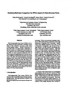
2.3 Impedance-based Structural Health Monitoring Impedance-based SHM uses piezoelectric patches that are bonded onto or embedded in a structure; each individual patch both actuates the surrounding structural area and senses the resulting structural response. This arrangement can be referred to as a “self-sensing actuator.” The size of the excited area varies with the geometry and material composition of the structure. An active patch is driven by a sinusoidal voltage sweep. When a piezoelectric is subjected to an electric voltage, it produces a mechanical strain; when a piezoelectric is stressed, it produces an electric voltage. Since each self-sensing actuator is bonded to the structure, driving a patch deforms and vibrates the structure—the structure then produces a localized dynamic response. This structural system response is transferred back to the patch, which in turn produces an electrical response. Figure 1 illustrates these basic concepts. The Figure 1 mechanical actuation and response is a function of the driving angular frequency Z 2S f , where f is frequency. The mechanical impedance is the complex ratio of force to velocity. The mechanical impedance is generally a complex function of frequency, because the force and the resulting velocity vary with frequency. This general definition is not unique, because the excitation region can be a finite area and the velocity can vary within this area. It is assumed that damage changes one or more of the basic structural parameters: mass, stiffness or damping. This in turn changes the mechanical impedance. The electrical impedance of the piezoelectric bonded onto the structure is directly related to the structure’s mechanical impedance. The impedance method of SHM operates by measuring this electrical impedance.
2
Figure 1. One-dimensional model of a piezoelectric-driven structure that models the piezoelectric as a thin bar in axial vibration, driven by an alternating voltage, with one end fixed and the other bonded to the structure. The structure has mass M, stiffness K, damping C, and one anchored end. The real part of the admittance (or impedance) is less sensitive to temperature variations and is more commonly used for SHM applications. The variation of the piezoelectric electrical impedance over a range of frequencies is analogous to structural frequency response function curves, and contains information directly indicative of structural health. In particular, the electrical impedance is measured at high frequency ranges (30-400 kHz) to ensure extreme sensitivities to minor defects in a structure. Typically, one volt or less is all the actuator driving voltage needed to produce local impedance excitations. It appears that the impedance method performs a complete measurement with less power than any other active SHM technique, making it the ideal path to autonomous, self-contained SHM. Previous work [Park et al. 1999, 2003] by the OMNI_THERM team further details the impedance method.
2.3.1 Advantages and Characteristics of the Impedance Method The impedance method has many advantages. We have already mentioned low power. Excitation occurs at small spatial scales, so the impedance method is very sensitive to changes in structural integrity, and often detects damage far earlier than alternative systems. The impedance method is insensitive to environmental and operational noise, and uses a known (active) excitation that simplifies data analysis and interpretation. We compare this method to some alternatives. Global vibrations: o Insensitive to early stage damage and sensitive to boundary condition variations. Acoustic emissions: o Not an active SHM approach—depends on uncontrolled ambient excitation that is difficult to interpret— active approaches have numerous advantages o Far field noise must be filtered out—the impedance method is near field and uses a localized, limited sensing area—there is no far field noise to remove. Off the Shelf Impedance Chip [Park et al. 2006]: o Needs external computing o Has low resolution, limited frequency range, and low excitation forces o Real impedance is difficult to obtain and may therefore be sensitive to temperature variations—causing false positives.
3
2.4 Energy Harvesting For aerospace damage monitoring it is desirable to have the monitoring unit be completely wireless. SAFE units will operate off harvested energy either directly or from a combination of duty cycle and storage in ultracapacitors (also called supercapacitors). Ultracapacitors are very robust, function well under harsh environmental conditions, and can be charged and discharged an order of magnitude more times than a battery. Ultracapacitors also have high energy-storage capacities (> 50 F), satisfy SAFE power demands (which are quite low), deliver high power bursts, and recharge rapidly. They are capable of over 600,000 charge cycles. With the proper duty cycle (that is time for charging versus time to run the monitoring system) even low levels of ambient energy can be stored and released to examine the structure at say 1-hour intervals. SAFE can thus be completely wireless and “place and forget,” and can provide regular (hourly) broadcasts of any possible induced damage in aerospace infrastructure—all without periodic maintenance to replace batteries. Recharging of the energy storage module can be done through piezoelectric, electromagnetic, solar or thermal based power harvesting. The particular choice depends on the nature of the ambient energy environment. Piezoelectric materials and electromagnetic systems have the unique property of being able to transform mechanical vibration into an electric charge. By using this property, piezoelectrics and/or electromagnetic micro generators mounted internally to a structure can harvest energy from a system’s own ambient motion and transform this mechanical kinetic energy into electrical potential. The resultant electrical energy can be used to recharge an ultracapacitor by employing power harvesting circuitry [Sodano at al 2003]. The harvested energy can be stored, or used to power devices directly—depending on the nature of the ambient vibrations. SAFE will use thermoelectric-based power harvesting in areas with suitable thermal gradients. SHM researchers have investigated thermoelectric-based power harvesting [Simmers et al. 2004]. Thermoelectrics consist of multiple P and N junctions connected electrically in series and thermally in parallel. These semi-conductive junctions are placed between two ceramic plates that aid heat transfer through the device; a heat sink is bonded to the top. These thermoelectrics can generate considerable power. Electrical power is generated as long as a temperature difference exists between the plates [Buist and Lau, 1997]. Finally, flexible thin-film solar panels can be integrated into structural surfaces (without effecting the aerodynamics; Anton 2008) to power SAFE and/or top up supercapacitors. Each of these harvesting modes can be combined or used individually, depending on the ambient operational environment.
2.5 SAFE Innovation Relative to Current Status and Feasibility 2.5.1 State of the General SHM Market SAFE addresses three general market needs: human safety, facility protection, and system operational efficiency. There is an urgent need to detect damage in crucial structural systems so as to safeguard humans, protect the structure itself, minimize operational downtime, and increase efficiency. The U.S infrastructure alone provides a host of SAFE applications. The U.S. Air Force is designing aircraft with century lifetimes, and needs to monitor crucial aircraft systems for damage during flight. Military experience with composite materials is transferring to commercial aircraft, with associated problems in repair and inspection. The need for aircraft SHM was graphically shown when structure-related crashes that included a horrific, video-documented airframe collapse and breakup, grounded the nation’s aerial firefighting fleet. Also, our country has 587,964 bridges, twenty eight percent of which need repair or replacement. The recent interstate bridge collapse in Minneapolis illustrates the importance of this market. Pipelines, dams, and earthquake and otherwise endangered civil structures each represent major markets.
2.5.2 State of the SHM Art As already mentioned, current health management methods are dominated by off-line non-destructive evaluation methods that do not provide on-demand health monitoring and damage evaluation and analysis during normal aircraft operations. Existing on-line aerospace monitoring methods are typified by passive approaches such as accelerometers and strain gauges. These methods are relatively insensitive and provide indirect measurement of damage and structural flaws. Alternative active SHM units require power and data wires, lack on-board processing 4
for autonomous operation, cannot be individually installed and freely embedded in complex structures, and require complex external support and data analysis. The proposed self-contained chip-level SAFE units provide a powerful and practical solution to the need for early detection of aging-related hazards in complex aviation and space structures.
2.5.3 SAFE Feasibility Previous LaRC sponsored work has clearly established SAFE feasibility. Specifically, there is an existing SAFE prototype that has been repeatedly tested and demonstrated on aerospace structures. Further, preliminary work in chip-level SHM architecture design has verified the feasibility of the recommended SAFE approach. The next steps include:
o o o o o
Modifying an existing prototype as required for composite material SHM; Identifying chip subthreshold building blocks for very low-power operation; Designing the architecture of the SHM chip; Modeling major building blocks of the SHM chip in a Hardware Description Language; and Demonstrating damage detection on real-world composite components.
Chip-specific results that identified chip subthreshold building blocks for very low-power operation, developed a SAFE chip architecture design, and modeled the chip in a Hardware Description Language, all verified that there are no major problems in implementing SAFE as a chip-level device.
3 Existing SAFE Prototype and Related Work 3.1 Existing SAFE Prototype There are currently two versions of the SAFE prototype. The existing prototype implements impedance-based SHM in a field deployable setup that includes the DSP-based system hardware shown in Figure 2. With the existing prototype, accurate approximations of the structural impedance can be determined without complex and expensive external electronic analyzers. All of the hardware needed to utilize the impedance method is condensed into a single digital signal processor (DSP) evaluation board. As Figure 2 shows, the current prototype consists of a TMS320F2812 evaluation board with a 150 MHz DSP and a 12 bit, 16-channel Analog-to-Digital Converter (ADC) with a 12.5 MHz conversion rate. Unlike previous efforts [Grisso and Inman 2006] that relied on a Digital-to-Analog Converter (DAC) for structural excitation, this prototype features new digital excitation and sensing techniques. The new completely digital technique eliminates both the DAC and ADC and significantly reduces SAFE power requirements. An additional prototype was developed with a microcontroller (MCU). The MCU used is a PIC model dsPIC30F6010A from Microchip. It has a 30 MHz operating frequency, 16 bit operation, and 8 Kbytes of SRAM memory. The MCU is contained on a dsPICDEM 80Pin Starter Development Board which measures 12.5 cm by 11.5 cm. The key feature of the MCU board is the built in prototyping area. The completed MCU prototype is shown in Figure 3. The Opamps, resistors, and two LEDs to indicate damage are all contained in the bottom right corner of the MCU development board.
5
The algorithm used for the DSP prototype was converted for use in the MCU. As with the DSP prototype, the MCU version was validated with the three-beam structure shown later (Figure 10). Damage is easily indicated when switching between the different beams.
3.2 Integration with Wave Propagation The existing impedance-based SHM prototype has also been modified to include wave propagation methods, and is referred to as the updated system. The updated system provides an option for future SAFE development and was designed to perform several tasks: generating signal excitation for the test structure, recording the response of the structure, and processing the acquired data. Figure 4 displays the hardware architecture necessary to implement this updated system. The major component added to the previous existing prototype is the inclusion of a digital-to-analog converter (DAC) for Lamb wave signal generation.
Figure 4. The hardware architecture for the Lamb wave based SHM system As shown in Figure 4, the DSP block is utilized as the core processing-unit for the whole prototype. The DSP provides a windowed excitation signal to the DAC, which converts the digital signal into a smoothed analog excitation wave. The driver converts the analog output current of the DAC into an excitation voltage signal for the structure. With the available current output of the DAC, one can obtain an excitation voltage with a high enough magnitude to greatly enhance the signal-to-noise ratio (SNR) without amplification. Once the structure has been excited with the DAC signal, the sensing unit, which consists of an amplifier and the internal ADC module in the DSP, acquires the data from the PZT sensors on the surface of the structure. The DSP core block processes the acquired data to determine whether there is damage or not and where the damage is located. Figure 5 shows a photograph of the complete updated prototype.
6
Figure 5. The complete updated prototype with labeled functional components The updated prototype has been tested with both pulse-echo and pitch-catch Lamb-wave damage detection algorithms. With the pulse-echo method, damage can be located by measuring the flight time of the reflected Lamb wave. With the pitch-catch method, one can estimate damage severity. Both methods require multiple steps to determine whether or not there is damage. The improved prototype was tested using a tri-axial woven polymer matrix composite (PMC) material designed for use in commercial fan cases [NASA Tech Brief 2006]. This particular material and application area is of specific interest to NASA. Note that the material is reinforced with triaxially braided carbon fibers.
4 Chip Design, Development and Verification Background 4.1 General Background In general, active SHM consists of two major functions: signal generation and response sensing. Typically, a PZT piezoelectric ceramic is utilized for excitation in the impedance method. The PZT transforms electrical energy into physical force, and converts physical force back to electrical energy [Park et al. 2003]. As shown in Figure 1, a PZT bonded to a structure reacts to a time varying voltage applied across two faces of the PZT, physically strains, and then applies a force to the structure. Single tone signals sweeping a certain frequency range are applied to the PZT, and its impedance is measured for each frequency. A DAC is usually used to generate single tone signals, and an ADC is used to sense the PZT electrical responses. A general-purpose digital signal-processing (DSP) chip typically generates the excitation signal and processes the response (Figure 6).
7
Figure 6. Simplified excitation and sensing block As mentioned earlier, running a SHM system off a battery or energy harvested from the environment is quite desirable, since this considerably reduces installation and maintenance costs. However, existing active SHM systems dissipate large amounts of power—on the order of several watts—and cannot run effectively off batteries or harvested energy. The electronics of such systems typically include DSP chips, ADCs and DACs. In order to reduce power consumption, a new, entirely digital system was recently developed; this system eliminates the need for analog-to-digital and digital-to-analog conversions. The key to this method is a drastic simplification of signal generation and response sensing. In order to simplify signal generation, the PZT is excited with a rectangular pulse train instead of single tone sinusoidal signals. A train of pulses with 50% duty cycle generates line spectrums at the fundamental frequency and odd harmonics as shown in Figure 7 (a). When the period of a pulse train is swept through the required frequency range, it effectively generates single tone signals (as well as their harmonics) for the frequency range. Harmonic terms do not pose any problem, as both the baseline and measured metrics are generated under the same excitation signals including harmonics. Figures 7 (b) and (c) show a train of pulses sweeping in the range of 40 kHz to 50 kHz and their corresponding line spectrum, respectively. As a DSP chip can easily generate a train of pulses, this approach greatly simplifies the signal excitation procedure while simultaneously eliminating the need for a DAC.
(a) Line Spectrum of a Pulse Train
(b) Sweeping Pulse Train from 40 kHz to 50 kHz
8
4
15
x 10
|X (f)|
10 5 0
0
0.5
1
1.5 2 Frequency (Hz)
2.5
3 5
x 10
(c) Line Spectrum of the Sweeping Pulse Train Figure 7. Generation of Excitation Signals In order to simplify response sensing, only the sign of the impedance value is observed—rather than observing the actual impedance value. In other words, the impedance value is quantized to only two levels, positive or negative, so that a comparator can be used instead of a power hungry ADC. This also substantially simplifies computational complexity, since binary values are utilized rather than integer values. This new procedure was carefully compared with procedures that use actual impedance values, and experimental results indicate that there is very little impact on damage detection [Kim et al 2007]. Figure 8 shows the general architecture of the SAFE system. The excitation signal x(t) is a train of pulses sweeping the required frequency range, and the OP amp output voltage z(t) represents the impedance of the PZT scaled by resistance R.
Figure 8. Overall Architecture of the SAFE System
9
Figure 9 shows the existing SAFE prototype monitoring several damage cases; this prototype employs the proposed signal generation and response sensing schemes. The signal processing for this prototype is performed by a 16-bit microcontroller instead of a DSP chip. This is made possible by the reduced computation complexity of this new, all-digital approach. Eliminating the DSP chip also significantly reduces the overall power dissipation. In comparison to an earlier, analog version of the autonomous active SHM system, the current digital prototype reduces power dissipation by more than an order of magnitude through reduced computation complexity and elimination of DAC and ADC components. This unit can run off a battery, and brings SAFE much closer to practical operation off harvested energy.
Figure 9. Existing prototype active SHM system monitoring three structural damage cases
4.2 SAFE Chip Development Objectives, Goals and Tasks The ultimate goal is to develop an active, multi-dimensional SHM system that powers itself with energy harvested from natural, ambient thermal gradients or structural vibrations. To accomplish this, the system must dissipate a minimal amount of energy. The current prototype SAFE system dissipates about 230 mW, which is too much power dissipation to operate on harvested energy in most natural environments. Power-hungry ADC and DAC components have been eliminated from this prototype, and the only remaining choice for further power reduction is to develop a low-power version of a custom ASIC (Application Specific Integrated Circuit) chip-level system tailored to SHM. This custom ASIC chip-level system is referred to as a SHM chip set—the projected and recommended SAFE system will include more than one such chip but can be a single chip in a final flight-qualified product. The low-power SHM chip design will exploit a unique characteristic of SHM signal processing. Specifically, this useful characteristic is that the time interval between two subsequent SHM operations is much longer than the operation time of the SHM system. For example, SHM may be performed once an hour or once a day or less, but SAFE will take less than one minute to complete one SHM operation. This means the processing time for SHM signal processing can be prolonged substantially without creating any practical problems. Subthreshold logic, in which logic circuits in CMOS technology operate below the threshold voltage, reduces power dissipation significantly—often by an order of magnitude—but speed is also significantly reduced [Wang et al. 2006]. Subthreshold logic is extremely power efficient, and is often the lowest power dissipation design for applications in which operating speed is not critical. The nature of SHM signal processing suggests that subthreshold logic is ideal for a SHM system, and early SAFE workers designed a subthreshold chip set tailored for the SAFE system. These researchers studied various subthreshold SHM chip designs targeted for SHM during previous work, and the next sections describe this work. The logical path forward therefore focuses on further development and construction of the final chip.
10
4.2.1 Chip Development—incorporation of SHM operational tools The first chip design and development task should aim to develop all the SHM operational tools that could potentially be incorporated into a final chip-level device. These tools will include additional damage detection techniques to supplement impedance-based SHM, as well as other analysis techniques and related structural tools. For example, this could incorporate the wave propagation SHM capabilities described earlier. The major tools should include:
1. The Lamb wave propagation technique for structural damage localization and quantification is an obvious choice to supplement impedance-based SHM. Lamb waves can utilize the same piezoelectric sensors as the impedance method. Also, while the impedance method is very sensitive to the presence of damage, Lamb wave are very useful in locating damage. 2. Vibration based methods are also a good compliment to the impedance method. While impedance-based SHM is a somewhat localized technique (damage can be seen in a limited area around the sensor), vibration techniques look for changes in the global modes of the structure. Exciting and sensing with the same piezoelectric material as impedance, Lamb wave, and vibration techniques look for indications of damage by examining and analyzing changes in the structural natural frequencies for mode shapes. Vibration sensors can also detect impacts and trigger a structural health state assessment. 3. Damage mitigation lets the hardware include methods of repairing early states of damage. Examples of damage mitigation include the restoration of bolt preload in a self-healing bolt, or self-healing composites with the ability to repair cracking due to impact or mechanical or thermal fatigue. Including damage mitigation directly into the hardware interface lets the autonomous SHM system determine whether healing has occurred and compensate for these beneficial structural changes. 4. Sensor diagnostics capabilities should also be a crucial part of the final chip-level SHM hardware. Instead of looking for damage to the host structure, sensor diagnostics looks at the integrity of the sensors themselves. Aviation and aerospace SHM sensors will need to be deployed in extreme environments that include conditions that could easily cause sensor damage. Sensors bonding to the structure may degrade over time, or the sensor itself may become damaged. In either case, the changes to the sensor may incorrectly show up as structural damage in the hardware analysis. Sensor diagnostics techniques allow the hardware to determine whether or not a sensor may be potentially damaged. Once the data from a particular sensor is deemed trustworthy or not, the damage detection analysis and procedure will carry on as normal. 4.2.2 Chip Development—SHM tools hardware implementation The second chip development task needs to implement these techniques using the currently existing hardware. Either the DSP or the MCU hardware platform can be used for this task. This step is needed to ensure the feasibility of each of the above methods for use in chip-level hardware. In fact, OMNI_THERM researchers have already implemented all of the techniques described above in one form or another on an evaluation board platform. At this point, it is prudent to test out any other tools that may potentially be included on the final hardware platform. For example, different energy harvesting techniques and circuitry arrangements will need to be analyzed at this hardware level.
4.2.3 Chip Development—PCB level prototyping The third chip design and development task is to develop the hardware and complete spectrum of SHM techniques and analysis tools onto an intermediate platform level. This intermediate level will be between the evaluation board stage and a chip set. Various methods can be used in this step. Three platforms are discussed; these include a fieldprogrammable gate array (FPGA), an application-specific integrated circuit (ASIC) or a printed circuit board (PCB) design. 11
A FPGA is a semiconductor device that contains programmable logic components. These “logic blocks” can be connected with programmable interconnects already built into the device. One way to think of a FPGA is a breadboard with all types of components available for use. Instead of manually wiring the necessary components together, the connections between logic components are programmed. FPGAs are very useful for prototyping and low volume production. Another major advantage of a FPGA is that the design can easily be changed through reprogramming. A major limitation of FPGAs is that the available components are largely digital, so FPGAs do not support systems such as operational amplifiers that need both digital and analog components. Operational amplifiers are often used at SHM system interfaces. In contrast, an ASIC is an integrated circuit designed for a specific application. As opposed to a FPGA, an ASIC is completely customized for a specific target application, and it can include any type of component (analog, mixed signal, and digital) to build a SHM system. However, ASICs do not allow design changes once fabricated. Also, ASIC development takes much more time (one to two years) and is more expensive than FPGA development. The PCB approach is slightly different from the above two approaches. Instead of programming predefined functions or designing specific functions, individual COTS (commercial off-the-shelf) hardware components are selected to perform the various functions. A PCB essentially holds and connects these COTS electrical components to build the desired system. In a sense, this is like designing a custom evaluation board with only the parts necessary for the SAFE system. This eliminates the unnecessary extras of COTS evaluation boards that are not useful for SAFE application. In this task, all three platforms should be employed to develop a SHM chip set. First, individual digital blocks of the SHM chip set should be modeled in an IEEE standard hardware description language, VHDL (VHSIC Hardware Description Language). Once the functionality of the VHDL model is verified through simulation, the model should be synthesized into gate level circuits and the digital blocks implemented on a FPGA board. Second, a PCB based prototype SHM system should be developed—this includes the FPGA board and a few analog components such as operational amplifiers for the interface. Finally, the prototype SHM system should be used to verify and demonstrate the operation of the SAFE SHM system (both hardware and software).
4.2.4 Chip Development—chip-level system implementation The final recommended chip-related task is to develop a chip-level system containing everything necessary for autonomous impedance-based SHM supplemented as desired by the SHM operational tools described earlier. To achieve this, ASIC chips will need to be designed and fabricated in deep submicron very-large-scale integration (VLSI) technology, specifically IBM 0.13 µm CMOS processing technology. A single ASIC ship in deep submicron VLSI technology can contain over a billion transistors, which lets designers put a highly complex system that includes digital, analog, mixed-signal and RF circuits on a single chip. Although VLSI technology enables building the entire SAFE SHM system on a single chip, a more practical and safer approach is to partition the system into multiple sub-blocks and build and test those individual sub-blocks separately. Once the functions of sub-blocks are verified and corrected, those sub-blocks are integrated into larger blocks in subsequent chip fabrications—and ultimately into a single block (chip). This process is commonly adopted in industry for the design of any complex system, and the same path is recommended here. The initial SAFE system will consist of multiple chips; with a single chip solution recommended for actual flight systems. The next several paragraphs explain general VLSI design flow, and then describe the design effort the recommended path forward will require. A VLSI design flow has many involved steps (Figure 10). Each level of the process must be completed to ensure that the end result is a functioning VLSI chip. The first step in VLSI design is defining the system specifications for the end product. These specifications can be anything from the operating speed of the final chip to power dissipation and actual chip size. Previous work covered much of this step.
12
Top Design Level
Bottom Design Level
Figure 10. The VLSI design hierarchy—from system specifications to finished chip [Uyemura 2002] The next step is developing abstract high-level models based on the system specifications. The entire system is partitioned into multiple functional blocks such as an arithmetic logic unit, a control unit, and a memory unit; each block is modeled in a hardware description language—VHDL, for SAFE. The block model specifies the block function at a high level—generally at the behavioral or the data flow level. The functionality of each individual model is verified through simulation. Once individual models are verified, they are integrated together into a single large model that represents the entire system. This step should be performed in Task 4.2.3—PCB level prototyping. Logic synthesis is the next step in the VLSI design hierarchy. The high-level model is synthesized into logic circuits using a logic synthesis tool. Logic circuits are simulated again for static timing verification and power estimates. The number of gates in a logic circuit provides a good estimation of system complexity. Task 4.2.4—system implementation—includes this step. Once the logic circuits are obtained, the circuits are placed and interconnected, i.e., routed, using a P&R (Place & Route) tool. Although this process is mostly automated, manual routing is necessary for any unfinished leftover routings. Analog and mixed-signal blocks and memory blocks are designed or generated separately, and they are also placed next to logic circuits at this step. Then the circuits at the transistor level and parasitics (such as wire delays) are extracted from the placed and routed circuits (both logic and analog/mixed signal) and simulated to check for timing violations. All timing violations are corrected by inserting buffers or by rerouting interconnections manually. System implementation includes this step. The final step is to extract a layout mask file from the placed and routed circuits and to submit this file to a foundry such as IBM. The layout mask file is called a GDSII file, and it is extracted using a CAD (Computer-Aided Design) tool. The foundry fabricates VLSI chips based on the GDSII file and sends the fabricated chips back to the designer. Chip fabrication can take three to six months. Finally, the designer tests the chip functionality and measures its performance. System implementation includes this step. The recommended path is to follow the general VLSI design flow described above, augmented with a few additional steps that are required for subthreshold circuit design. After the logic circuits are obtained through the logic synthesis step, the speed of individual blocks should be examined by lowering the supply voltage. As the supply voltage is lowered, the speed (and power dissipation) of individual blocks decreases, and some of the blocks will probably eventually fail to meet the speed requirements set by the system specifications. One should then analyze each failing block and pinpoint the exact spot that causes speed failure. Those failing spots should then be redesigned at the transistor level (rather than at the logic level) to increase the speed. One simple redesign measure to consider is increasing the transistor sizes at those spots. Other subthreshold design schemes should also be considered. It appears that most blocks of the SAFE SHM chip set can operate in the subthreshold region, since the 13
required system speed is very low in all but a couple of blocks. Finally, each block should be fabricated as a single chip, or combined with a few additional blocks into a single chip. One might expect the SAFE chip set to consist of three or four individual chips; these should then be combined into a true single-chip system following aircraft verification and other test and development prior to final flight certification. As these steps reveal, the VLSI design hierarchy is quite complicated. The total design process can take up to 2 or 3 years, and chip manufacturing can take several to six months. Once SAFE hardware development and system functionality is complete, we will be well on the way to having a custom chip-level system for autonomous SHM.
5 SAFE System Testing and Validation The SAFE system proposed here should be tested and validated through a series of engineering laboratory tests and aircraft flight demonstrations. Some options are presented here.
5.1 Demonstrate Damage Detection in a Model Composite NASA OMNI_THERM researchers have done previous damage detection demonstrations on composites that include Boeing CEV TPS and experimental wind turbine blades (see Part 6). SAFE chip-level hardware should be demonstrated and verified though damage detection demonstrations in model composites that include sandwich structures. Composite materials for testing might include the tri-axial woven polymer matrix composite (PMC) material already mentioned. The strength of braided composite fan casings increases aircraft safety by containing loose jet engine fan blades. These carbon-braided structures also have weight advantages that lower costs and fuel consumption. Focus should be on the impedance method, with wave propagation techniques optional. The impedance method could be used for initial damage detection, supplemented by analysis with wave propagation methods. In addition to demonstrating efficacy and defining system performance, these test results also provide further engineering feedback for chip development.
5.2 Conduct Flight Demonstrations and Tests in Aircraft It is crucial that SAFE hardware be demonstrated and verified through a series of real world aircraft flight tests. At a minimum, SAFE should demonstrate damage detection in airframe structures during straight and level flight. There are numerous candidate flight research platforms; this section mentions a Learjet and two NASA Dryden Flight Research Center platforms.
5.2.1 Learjet 25 Aircraft The instrumented Learjet 25 aircraft has been regularly used for cloud physics research. The Learjet described here has participated in several NASA and NSF field projects (NASA TRMM, NASA EOS validation, and others) and is a well-established research aircraft. The Learjet of interest is completely equipped with data acquisition and data management systems, as well as a host of environmental sensors and support systems. In addition to temperature, dew point, altitude, airspeed, 14
aircraft position, aircraft heading, and cloud physics sensors, this Learjet includes a complete SEA data acquisition system. This includes various instrument-specific data streams that can be time-synchronized. There are also three flat-panel data display units. Learjet 25 airframe structural elements are readily accessible, and it should therefore be straightforward to detect simulated airframe damage using SAFE hardware. For example, one can simulate damage by adding controlled masses to airframe elements; this does not directly damage the airframe. One could then use SAFE to detect mass addition and subtraction during flight. This procedure is commonly used to simulate damage under laboratory conditions; this technique should transfer to flight conditions.
5.2.2 NASA Dryden Flight Research Center Aircraft There are at least two very interesting flight test options based on NASA Dryden FRC research platforms. These two platforms are the Aerostructures Test Wing (ATW) and the C-17 airlifter.
5.2.2.1 Aerostructures Test Wing (ATW) The ATW is an 18-inch carbon-fiber test wing with embedded piezoelectric strain actuators. This test wing has previously flown on Dryden’s F-15B Research Testbed aircraft. The actuators were excited at different frequency levels and amplitudes to induce flutter. The ATW was intentionally fluttered to the point of structural failure at the final test point of Mach 0.85 at an altitude of 10,000 feet—as a result about a third of the wing broke off. DFRC plans to re-fly the ATW. Direct examination of the current ATW configuration revealed no incompatibilities between the ATW test geometry and SAFE hardware. This is an exceptional opportunity to perform a definitive SHM test and demonstration, since the test culminates with major structural damage. Most previous tests have involved simulated damage. If at all possible, flying the ATW research platform as a SHM/IVHM-specific research project is strongly recommended. That is, the ATW would be configured and flown with specific SHM goals and would include SAFE sensors. The ATW should first be studied and characterized in wind tunnels with the objective of implementing damage prognosis and predicting structural failure during flight using SAFE systems.
15
5.2.2.2 C-17 Globemaster III The C-17 Globemaster III strategic airlifter is capable of rapid strategic delivery of all types of cargo; it can also perform tactical airlift, medical evacuation, and airdrop missions. It is particularly well suited to large and heavy oversized cargo. Cargo is loaded through a large aft door that accommodates both rolling stock (vehicles, trailers, etc.) and palletized cargo. The cargo floor has rollers for palletized cargo; these rollers can be flipped to provide a flat floor suitable for rolling stock. The C-17 can carry the 70-ton M1 Abrams tank. Maximum payload capacity is 170,900 lbs (Wikipedia). The Dryden C-17 is operated by the Air Force and flies regularly. C-17 operations personnel indicate that it should be possible to “piggy-back” on one or more of these missions at nominal cost. There is ready access to the interior airframe structure, and it should be straightforward to perform SAFE flight tests on this flight platform. If SAFE research were to exercise this flight option, one could use an inactive adhesive to bond a PZT to the airframe interior, and then clamp a series of calibrated masses to the interior airframe structure at various distances from the PZT patch. Mass addition and subtraction would simulate damage and repair. SAFE would then demonstrate mass detection (damage detection) during straight and level flight.
Concluding Remarks This position paper has discussed the significance and considerable benefits of implementing a SHM strategy for aviation and space infrastructure. We have outlined and recommended a specific SHM technical approach, and made recommendations for tests and demonstrations that will encourage acceptance of SHM in the aerospace community. We refer to our SHM strategy and technical approach as SAFE (Structural Assessment in Flight Environments). We recommend:
o o o
Implementing an impedance-based SHM system by converting an existing prototype into a chipbased device; Performing system validation through a series of aircraft-based tests and demonstrations; and Using the existing NASA Dryden ATW (Aerostructures Test Wing) research platform specifically for SHM tests, as well as the use of other aviation research platforms and test beds such as the C-17 Globemaster III strategic airlifter available at Dryden.
16
Glossary ADC: Analog-to-Digital Converter. Aerostructures Test Wing (ATW): A NASA Dryden flight research platform that examines wing flutter. ASIC: Application-Specific Integrated Circuit—an integrated circuit designed for a specific application. CAD: Computer-Aided Design. CEV: Crew Exploration Vehicle. CIMSS: Virginia Tech Center for Intelligent Material Systems and Structures. CMOS: Complementary-Metal-Oxide-Semiconductor. COTS: Commercial Off-the-Shelf. DAC: Digital-to-Analog Converter. DSP: Digital Signal Processor. Energy harvesting: An approach to self-power that harvests ambient energy (vibration, electromagnetic, heat, light) for system power. EOS: Earth Observing System. FPGA: Field-Programmable Gate Array—a semiconductor device that contains programmable logic components. GDSII file: VLSI chip layout mask file. Impedance-based structural health monitoring: A specific structural health monitoring approach that indirectly and locally measures the mechanical impedance of the structure of interest in order to detect damage and assess structural integrity. IVHM: Integrated Vehicle Health Management. Lamb waves: Elastic acoustic waves that propagate in solid plates and are guided by the boundaries of the media in which they propagate. LED: Light Emitting Diode. MCU: Microcontroller. Non-Destructive Evaluation (NDE): Off-line damage detection and structural evaluation that is non-destructive and allows the system of interest to be returned to normal operation. NREL: National Renewable Energy Laboratory. NWTC: National Wind Technology Center. OMNI_THERM: An autonomous structural health monitoring system that implements the impedance-method in a self-contained, low-power, wireless configuration. Op-Amp: Operational Amplifier. PCB: Printed Circuit Board. Piezoelectric (PZT): An active material that generates motion when electrically activated and vice-versa. Pitch-and-catch method: A method of damage detection that relies on multiple sensors to analyze Lamb waves. Pitch-and-echo method: A method of damage detection that relies on measuring the flight time of a reflected Lamb wave. PMC: A Polymer Matrix Composite material expected to find use in next-generation aircraft engine fan cases. PWM: Pulse-width modulation. 17
Self-sensing actuator: A piezoelectric patch that both excites and actuates the structure of interest and senses structural response. SHM operational tools: A toolset of SHM tools and methods for comprehensive damage detection and structural integrity evaluation. Structural Assessment in Flight Environments (SAFE): The structural health monitoring technical approach and technology recommended in this position paper. Structural Health Monitoring (SHM): A damage detection strategy based on in-place sensors and damage detection systems and support elements that provide on-line damage detection capabilities during normal infrastructure operations. Subthreshold logic: CMOS logic circuits that operate below threshold voltage, generally with the goal of reducing power dissipation. TPS: Thermal Protection System. TRMM: Tropical Rainfall Measuring Mission. VHDL: VHSIC Hardware Description Language—an IEEE standard hardware description language. VLSI: Very-Large-Scale Integration.
18
References Anton, S. A, Improving Baseline Management and the Energy Supplies of Structural Health Monitoring Systems, MS Thesis, July 2008, Virginia Tech, Department of Mechanical Engineering. Buist, J. and P. Lau (1997) “Thermoelectric power generator design and selection from TE cooling module specifications,” Proc. XVI Int’l Conf. Thermoelectrics, Dresden, Germany. Chronkhite and A. Gill (1999) Research and Technical Organization (RTO) Technical Publication No. 0046347. “Damage-tolerant fan casings for jet engines,” NASA Tech Briefs, Jan 01 2006. Grisso, B. L. and D. J. Inman (2006) “Impedance-based structural health monitoring of thermal protection systems,” Nondestructive evaluation for health monitoring and diagnostics SPIE conference, 26 Feb – 2 Mar, San Diego CA. Hundhausen, R. J., D. E. Adams and M. M. Derriso “Identification of damage in a standoff metallic thermal protection system panel subjected to combined thermo-acoustic excitation,” 10th SPIE International Symposium: Nondestructive evaluation for health monitoring and diagnostics, 6–10 March 2005, San Diego CA. Kim, J., B. L. Grisso, D. S. Ha and D. J. Inman (2007) “A system-on-board approach for impedance-based structural health monitoring,” Smart structures and materials & nondestructive evaluation and health monitoring, 14th International Symposium, 18–22 March, San Diego CA, SPIE Proceedings Volume 6529. Lynch, J.P., Sundararajan, A., Law, K.H., Kiremidjian, A.S., Kenny, T.W., Carryer E. (2003) “Embedment of structural monitoring algorithms in a wireless sensing unit,” Structural Engineering and Mechanics, 15: 285–97. Newman, J. W. (2005) “Holographic and shearographic NDT applications in aerospace manufacturing,” Materials Evaluation 63(7): 746-50. Park, G., Kabeya, K., Cudney, H. H. and Inman, D. J. (1999) “Impedance-based structural health monitoring for temperature varying applications,” JSME International J., Series A, 42(2): 249–58. Park, G., H. Sohn, C. R. Farrar and D. J. Inman (2003) “Overview of piezoelectric impedance-based health monitoring and path forward,” The Shock and Vibration Digest, 35(6): 451–63. Park, S., B. L. Grisso, D. J. Inman and C. B. Yun (2006) “MFC-based corrosion detection using a miniaturized impedance measuring chip,” Proceedings of 4th World Conference on Structural Control and Monitoring, July 11– 13, San Diego CA, 2006. Pitchford, C., B. L. Grisso and D. J. Inman (2007) “Impedance-based structural health monitoring of wind turbine blades,” Smart structures and materials & nondestructive evaluation and health monitoring, 14th International Symposium 18-22 March, San Diego CA. Simmers, G. E., H. A. Sodano and D. J. Inman (2004) “Use of piezoelectric materials to harvest power from waste heat and vibrations found in a standard automobile,” CIMSS report. Sodano, H. A., G. Park, D. J. Leo, and D. J. Inman (2003) “Use of piezoelectric energy harvesting devices for charging batteries,” Proceeding of SPIE’s 10th Annual International Symposium on Smart Structures and Materials, Vol. 5050. “Special report: nuclear power, the shape of things to come,” The Economist Vol. 376 No. 8434 pp. 58-60, Jul. 9 2005. 19
Spencer, B.F., Ruiz-Sandoval, M.E., Kurata, N. (2004) “Smart sensing technology: Opportunities and challenges,” Journal of Structural Control and Health Monitoring, 11: 349-68. Straser, E.G. (1998) A modular, wireless damage monitoring system for structures, Ph.D. Thesis, Department of Civil and Environmental Engineering, Stanford University, Stanford, CA. Tanner, N.A., Wait, J.R., Farrar, C.R., Sohn, H. (2003) “Structural health monitoring using modular wireless sensors,” Journal of Intelligent Material Systems and Structures, 14: 43–56. Uyemura, J. P., 2002, Introduction to VLSI Circuits and Systems, John Wiley & Sons, Inc. New York, NY. Wang, A., B. H. Calhoun, and A. P. Chandrakasan (2006) Sub-threshold Design for Ultra Low-Power Systems, New York: Springer.
20
Form Approved OMB No. 0704-0188
REPORT DOCUMENTATION PAGE
The public reporting burden for this collection of information is estimated to average 1 hour per response, including the time for reviewing instructions, searching existing data sources, gathering and maintaining the data needed, and completing and reviewing the collection of information. Send comments regarding this burden estimate or any other aspect of this collection of information, including suggestions for reducing this burden, to Department of Defense, Washington Headquarters Services, Directorate for Information Operations and Reports (0704-0188), 1215 Jefferson Davis Highway, Suite 1204, Arlington, VA 22202-4302. Respondents should be aware that notwithstanding any other provision of law, no person shall be subject to any penalty for failing to comply with a collection of information if it does not display a currently valid OMB control number. PLEASE DO NOT RETURN YOUR FORM TO THE ABOVE ADDRESS.
1. REPORT DATE (DD-MM-YYYY)
2. REPORT TYPE
01- 05 - 2011
3. DATES COVERED (From - To)
Contractor Report
4. TITLE AND SUBTITLE
5a. CONTRACT NUMBER
Hardware Specific Integration Strategy for Impedance-Based Structural Health Monitoring of Aerospace Systems
NNX08CB23P 5b. GRANT NUMBER 5c. PROGRAM ELEMENT NUMBER 5d. PROJECT NUMBER
6. AUTHOR(S)
Owen, Robert B.; Gyekenyesi, Andrew L.; Inman, Daniel J.; Ha, Dong S. 5e. TASK NUMBER 5f. WORK UNIT NUMBER
284848.02.03.07.01 7. PERFORMING ORGANIZATION NAME(S) AND ADDRESS(ES)
8. PERFORMING ORGANIZATION REPORT NUMBER
NASA Langley Research Center Hampton, VA 23681-2199
9. SPONSORING/MONITORING AGENCY NAME(S) AND ADDRESS(ES)
10. SPONSOR/MONITOR'S ACRONYM(S)
National Aeronautics and Space Administration Washington, DC 20546-0001
NASA 11. SPONSOR/MONITOR'S REPORT NUMBER(S)
NASA/CR-2011-217153 12. DISTRIBUTION/AVAILABILITY STATEMENT
Unclassified - Unlimited Subject Category 33 Availability: NASA CASI (443) 757-5802 13. SUPPLEMENTARY NOTES
Langley Technical Monitor: William C. Wilson 14. ABSTRACT
The Integrated Vehicle Health Management (IVHM) Project, sponsored by NASA’s Aeronautics Research Mission Directorate, is conducting research to advance the state of highly integrated and complex flight-critical health management technologies and systems. An effective IVHM system requires Structural Health Monitoring (SHM). The impedance method is one such SHM technique for detection and monitoring complex structures for damage. This position paper on the impedance method presents the current state of the art, future directions, applications and possible flight test demonstrations.
15. SUBJECT TERMS
IVHM, Impedence Method, NDE, SHM, Wireless 16. SECURITY CLASSIFICATION OF: a. REPORT
U
b. ABSTRACT c. THIS PAGE
U
U
17. LIMITATION OF ABSTRACT
UU
18. NUMBER 19a. NAME OF RESPONSIBLE PERSON OF STI Help Desk (email:
[email protected]) PAGES 19b. TELEPHONE NUMBER (Include area code)
26
(443) 757-5802 Standard Form 298 (Rev. 8-98) Prescribed by ANSI Std. Z39.18