This article has been accepted for inclusion in a future issue of this journal. Content is final as presented, with the exception of pagination. IEEE TRANSACTIONS ON SMART GRID
1
Harmonic and Negative-Sequence Current Control in an Islanded Multi-Bus MV Microgrid Mohsen Hamzeh, Student Member, IEEE, Houshang Karimi, Senior Member, IEEE, and Hossein Mokhtari, Member, IEEE
Abstract—This paper presents a multifunctional control strategy for the autonomous operation of a multi-bus medium voltage (MV) microgrid under nonlinear and unbalanced load conditions. The main objective is to effectively compensate the harmonic currents of nonlinear loads using electronically-coupled distributed generation (DG) units. The proposed control strategy consists of a multi proportional resonant controller (MPRC) with adjustable resonance frequency and a harmonic impedance controller (HIC). The MPRC and HIC are, respectively, proposed to regulate the microgrid voltage and to share the harmonic currents of the nonlinear loads among the DG units. A conventional droop scheme is also employed to share the average powers of the loads between the DG units. Moreover, a virtual negative-sequence impedance control loop is augmented to the proposed control system to compensate the negative-sequence currents of the unbalanced loads. The proposed strategy minimizes the flow of harmonic and negative-sequence currents in the MV lines of the microgrid by local compensation of harmonic and negative-sequence currents of the feeders. The performance of the proposed control scheme is verified by using digital time-domain simulation studies in the PSCAD/EMTDC software environment. Index Terms—Distributed generation, harmonic current, microgrid, negative-sequence, unbalanced and nonlinear loads.
I. INTRODUCTION
M
ICROGRIDS aim to provide a solution to move the conventional power systems toward a new concept for future energy distribution systems. With recent developments in smart grid concept and the associated advancement in communication, instrumentation, and control techniques utilized by the electronically-coupled DG units, the flexible control of microgrids for improving power quality is becoming a promising topic. The proliferation of nonlinear loads in the distribution networks results in various power quality problems for microgrids. Moreover, a microgrid may inherently be subjected to significant degrees of unbalanced conditions due to the presence of single-phase loads and/or DG units. Nevertheless, a microgrid should be able to operate under nonlinear and unbalanced load
Manuscript received November 06, 2012; revised February 20, 2013 and April 20, 2013; accepted May 14, 2013. Paper no. TSG-00775-2012. M. Hamzeh and H. Mokhtari are with the Center of Excellence in Power System Management and Control, Sharif University of Technology, Tehran, Iran (e-mail:
[email protected];
[email protected]). H. Karimi is with the Département de Génie Électrique, École Polytechnique de Montréal, Montréal, QC, Canada (e-mail:
[email protected]). Color versions of one or more of the figures in this paper are available online at http://ieeexplore.ieee.org. Digital Object Identifier 10.1109/TSG.2013.2263842
conditions without any performance degradations. Based on the IEEE standards [1]–[3], the voltage total harmonic distortion (THD) and the voltage unbalance factor (VUF) for sensitive loads should be maintained below 5% and 2%, respectively. Besides the primary purpose of a DG unit which is power generation, a DG can provide the utility system with different services. These services include voltage support, power factor correction, harmonic compensation, and voltage unbalance compensation [4]–[7]. Several control techniques for reducing the voltage THD of an inverter under nonlinear load conditions have been presented, e.g., passive filters and active damping control [8]–[10]. However, these methods are only intended for single-bus microgrids and their effectiveness for multi-bus microgrid applications has not been investigated. To compensate the impact of nonlinear and unbalanced loads, a proportional-resonant controller is presented in [6]. In the proposed method, there is a tradeoff between the compensation of the voltage THD and the accuracy of harmonic current sharing. Among the compensation schemes proposed in the literature, the repetitive control appears to be a practical solution for harmonic compensation. The method provides an exact asymptotic tracking of a periodic input signal and good rejection of periodic disturbances [8], [11]. The methods presented in [12] consider the DG unit as a negative-sequence conductance and make the DG voltages balanced. The negative-sequence voltage is compensated by generating a reference signal based on a negative-sequence reactive power. In [7], a control strategy is proposed for a multi-bus MV microgrid under unbalanced load conditions. The proposed control strategy shows a good performance in the microgrids with linear loads. This paper presents a new multifunctional control strategy for harmonic current compensation in an islanded widespread microgrid consisting of multiple buses and several dispatchable electronically-interfaced DG units. The overall microgrid is controlled based on a decentralized control strategy, i.e., each DG unit is locally controlled using a multifunctional control scheme. However, it is assumed that each 20 kV feeder of the microgrid is equipped with a measurement unit which can transmit the effective value of harmonic current and phasor of negative-sequence current of each feeder to the neighborhood DG units. The proposed control strategy consists of a multi proportional resonant controller (MPRC), a droop controller, a harmonic impedance controller (HIC), and a virtual negative-sequence impedance controller (VNSIC). The MPRC robustly regulates the load voltage under nonlinear and unbalanced load conditions. The HIC is proposed to efficiently share the harmonic
1949-3053/$31.00 © 2013 IEEE
This article has been accepted for inclusion in a future issue of this journal. Content is final as presented, with the exception of pagination. 2
IEEE TRANSACTIONS ON SMART GRID
TABLE I MICROGRID PARAMETERS
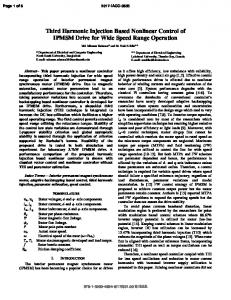
Fig. 1. (a) MV multi-bus microgrid consisting of two dispatchable electronically-coupled DG units and a synchronous generator. (b) Structure of the electronically-coupled DG unit connected to the MV feeder.
currents of the nonlinear loads among the DG units. The VNSIC is used to share the negative-sequence currents of unbalanced loads among the neighboring DG units. The HIC adjusts the harmonic impedance of the corresponding DG unit such that the accurate harmonic current sharing is achieved. The proposed strategy minimizes the flow of harmonic and negative-sequence currents in the MV lines of the microgrid by local compensation of harmonic and negative-sequence currents of the feeders. The simulation studies conducted in the PSCAD/EMTDC environment verify that the proposed method effectively copes with the inclusion of nonlinear and unbalanced loads at the local and nonlocal feeders. II. DESCRIPTION OF MULTI-BUS MV MICROGRID A single-line diagram of the under study multi-bus MV microgrid is shown in Fig. 1(a). The microgrid is assumed to operate in an islanded mode, and comprises a 20-kV four-feeder distribution system, two electronically-coupled three-wire dispatchable DG units and a synchronous generator (SG) unit. The electronically-coupled DG units are able to supply any amount of positive-sequence, negative-sequence and harmonic currents within the pre-specified limits. Fig. 1(b) shows the structure of the DG unit used in the microgrid of Fig. 1(a). The DG units supply MV feeders through step-up transformers. The dc side of each inverter is equipped with a hybrid energy resource containing a main source, an auxiliary source, and a fast dynamic response storage device (surge unit). The main source must be a dispatchable energy resource such as a fuel cell or a combustion engine. The auxiliary source can be one of the nondispatchable renewable
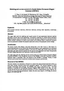
energy sources such as a PV or a wind power system. The utilized hybrid energy resource provides an almost constant dc-bus voltage for the inverter [13]. Therefore, the energy source of each DG unit is modeled by an ideal dc voltage source. The loads which can be nonlinear and unbalanced are supplied through three radial feeders , and . The DG units supply feeders and through step-up transformers. The loads do not absorb any zero-sequence and third-order harmonic currents from the MV feeders as they are connected to the MV feeders via transformers. The microgrid parameters are given in Table I. III. OPERATION PRINCIPLES OF THE PROPOSED CONTROL STRATEGY The control strategy of each DG unit consists of a proposed harmonic current control, a negative-sequence current controller, a voltage control unit, and an average power sharing unit. The voltage controller regulates the microgrid voltage using a multi proportional resonant controller (MPRC) whose resonance frequency is determined by the droop controller. Under nonlinear and/or unbalanced load conditions, the load powers assume average (dc) as well as oscillatory components [14]. In this case, the conventional droop controller is used to share the average powers of the loads, and a control scheme is proposed to appropriately share the oscillatory power components among the DG units. The proposed controller adjusts the output impedance of each DG unit at the frequencies where the harmonics and negative-sequence currents are centered. Each DG unit mainly compensates the oscillatory powers, i.e., harmonic and negative-sequence currents, of its local load, whereas the oscillatory powers of the nonlocal loads are shared among all DG units according to their harmonic and negative sequence current capacities. Fig. 2 shows the block diagram of the proposed multifunctional control system. Each unit of Fig. 2 will be discussed in details in the sections to follow. The dynamic model of a three-wire inverter in the stationary reference frame ( -frame) as presented in [7] is used in this
This article has been accepted for inclusion in a future issue of this journal. Content is final as presented, with the exception of pagination. HAMZEH et al.: HARMONIC AND NEGATIVE-SEQUENCE CURRENT CONTROL IN AN ISLANDED MULTI-BUS MV MICROGRID
3
Fig. 2. Structure of proposed control system including voltage controller, average power sharing unit, harmonic, and negative-sequence current controllers.
TABLE II CONTROLLER PARAMETERS
. The output current which is considered as a disturbance signal contains the fundamental and higher order harmonics when a nonlinear load is supplied. To achieve zero steady state error for the closed-loop system in the presence of harmonic currents, a multi-PR controller is proposed as
(1) compensates the current harmonic, and is a lead compensator which guarantees the robust stability of the closed-loop voltage control system. The transfer functions for , , and are paper. As shown in average power sharing control block, Fig. 2, the instantaneous real and reactive powers of the DG units are applied to the low pass filters (LPFs) with the cutoff frequency of 10 Hz to eliminate the high frequency ripples. The average powers are then used by the droop unit for computing the reference signals of the voltage controller. The droop coefficients are determined based on the DG power rating and the maximum allowable deviations of frequency and voltage magnitude [15]. The reference generator unit generates the reference signals and for the voltage control unit. To increase the internal stability of the voltage control loop and to protect the inverter switches against any over-current, an inner current loop is also incorporated. The current controller is a positive gain, , whose value is calculated such that the damping factor of the dominant poles of the inner loop system becomes 0.7. In Fig. 2, and are the output currents of the inverter, and and denote the series filter currents in the -frame. To reject the impact of load dynamics, the output current is fedforward to the voltage control loop as shown in Fig. 2. The resultant signals are then applied to the current controllers to generate the control signals and . According to the internal model principle, a reference (disturbance) signal can asymptotically be tracked (rejected) if its Laplace transform is included in the controller. Therefore, the steady state error for a sinusoidal reference signal with frequency will be zero if the controller contains the term
(2) is the system nominal frequency and is a small In (2), positive number which is used to limit the gain of open-loop system at . The value of is determined by the harmonic impedance controller (HIC). The output impedance of the inverter at each specific harmonic is adjusted by . It should be noted that only harmonic currents up to the 13th order are compensated since the bandwidth of the voltage control system is limited to 900 Hz. Similar to a notch filter, each harmonic compensator has a narrow bandwidth with a high magnitude centered at its resonance frequency, and very low magnitude elsewhere. Hence, the interactions between the harmonic compensators are very low and can be neglected. To achieve a good robust stability margin, an excellent noise immunity and harmonic rejection, and to obtain a fast transient response, a phase margin of 30 and a bandwidth of 900 Hz are considered. Considering the aforementioned performance indices and using MATLAB SISO tools, the coefficients of the designed controller are obtained and given in Table II. To control the output impedance of the inverter at a specific harmonic, the parameter in is externally manipulated
This article has been accepted for inclusion in a future issue of this journal. Content is final as presented, with the exception of pagination. 4
Fig. 3. Block diagram of
IEEE TRANSACTIONS ON SMART GRID
-order harmonic compensator
.
Fig. 5. Frequency response of the output impedance of the closed-loop DG for three values of . system
Fig. 4. Bode plots of loop transfer function of control system for three values of .
by the HIC unit as shown in Figs. 2 and 3. Note that since the fundamental frequency may slightly deviate from its nominal value by the droop controller, it is externally adjusted in as shown in Fig. 3. Fig. 4 shows the bode plots for the loop transfer function of the voltage control system for three values of when the parameters of Tables I and II are used. It should be noted that the stability margins (phase and gain margins) of the voltage control system do not change considerably as increases from 1.5 to 60 rad/s. The output impedance of the inverter in the or axis is defined as
(3) where and are, respectively, the terminal current and the output voltage of the DG unit in the or axis. Fig. 5 shows the frequency response of in the per unit form for three values of . As it is observed, significantly increases at the harmonics frequencies when the value of is increased. Fig. 5 verifies that the parameter can be used to control the output impedance of the inverter at a specific harmonic frequency. By adjusting the harmonic impedance of each electronically-coupled DG unit, the harmonic currents among the DG units can be controlled.
As shown in Fig. 2, to control the negative-sequence output impedance of each DG unit, a virtual impedance control loop is augmented to the proposed control system. The output current of each DG unit is decomposed into its symmetrical components using the unified three-phase signal processor (UTSP) presented in [16]. The UTSP system is able to accurately extract the symmetrical components of its input signal even in a harmonic and noisy environment. The UTSP parameters are set such that the transient response of the voltage control loop becomes less than one cycle. The instantaneous negative-sequence components of the DG current, i.e., and , are multiplied by an inductive impedance gain, , which is determined by a virtual negative-sequence impedance controller (VNSIC) (Fig. 2). A. Positive-, Negative-sequence and Harmonic Models of DG Based on Fig. 2, the output voltages of the closed-loop system in the or axis can be expressed as
(4) where and are the voltage reference and the DG terminal current, respectively, and is the inverter output impedance as defined in (3). is the negative-sequence of the fundamental component of and is the virtual impedance generated by the VNSIC. The closed-loop transfer function from the reference voltage to the output voltage is denoted by [7]. Equation (4) can be decomposed into positive-sequence, negative-sequence and harmonic components as
(5)
This article has been accepted for inclusion in a future issue of this journal. Content is final as presented, with the exception of pagination. HAMZEH et al.: HARMONIC AND NEGATIVE-SEQUENCE CURRENT CONTROL IN AN ISLANDED MULTI-BUS MV MICROGRID
5
Fig. 6. (a) Positive-sequence model and (b) negative-sequence model, and (c) harmonic model of a DG unit in or axis.
Fig. 7. Negative-sequence output impedance of the closed-loop DG system for . three values of
Based on (5), the positive-sequence, negative-sequence and harmonic models of the DG unit are obtained as shown in Fig. 6. According to [7], since , the positive- and negative-sequence output impedances of the DG unit at the system frequency can be expressed as (6) is a small value, the magAs shown in Fig. 5, since nitude of is dominantly controlled by using the VNSIC. Fig. 7 shows the negative-sequence output impedance of the DG unit for three inductive values of . The negativesequence output impedance of the DG is adjusted by manipulating the gain . The negative-sequence current sharing is carried out by adjusting of each DG unit. The output impedance of the DG unit at the harmonic can be expressed as: (7) is set by . where The parameter is generated by the HIC unit. The magnitude and phase-angle of the DG output impedance for harmonics 5th, 7th, 11th and 13th versus are plotted in Figs. 8. The studies show that the magnitude responses of the impedances are proportional to the value of . The maximum permissible values for and can be calculated based on the IEEE standards [1], [3], i.e.,
(8)
Fig. 8. Effect of
on harmonic output impedance of the inverter.
Moreover, the capability of an inverter for injecting the harmonic and negative-sequence current is a limiting factor which together with (8) determine the maximum value of the harmonic and negative-sequence output impedances. B. Harmonic Current Sharing Strategy Each DG unit mainly compensates harmonic current of its local nonlinear load, and those of the nonlocal loads are compensated by all DG units based on their harmonic current capacities. The reference signal of the HIC of each DG unit, i.e., in Fig. 2, is calculated as
(9) is the effective value of the harmonic current of the where local load, is the maximum harmonic current that the DG can inject, and is the effective value of the harmonic current of the feeder supplying the nonlocal loads. Moreover, the reference signal of the VNSIC, i.e., in Fig. 2, is calculated using the strategy discussed in [7]. It should be noted that if the impedances of the MV lines from the nonlocal loads to the adjacent feeders are known, the harmonic impedance of the inverter can be controlled by the parameter in an off-line manner. However, in a real distribution power system, network parameters may be unknown. Hence, off-line coordination of the DG output impedances for harmonic and negative-sequence current sharing may not be feasible. To achieve the accurate harmonic and negative-sequence currents sharing, the effective value of the harmonic current and the phasor of the negative-sequence current of each nonlocal load must be measured and transmitted to all DG units. This can be performed by a low bandwidth communication link. Notice that if the communication links are lost, harmonic and negative-sequence currents sharing are carried out in off-line manner based
This article has been accepted for inclusion in a future issue of this journal. Content is final as presented, with the exception of pagination. 6
IEEE TRANSACTIONS ON SMART GRID
on the prespecified values of the lines and transformers impedances. Nevertheless, failure of communication links does not have any impact on the voltage and frequency control loops since these control strategies operate based on local measurements. When the HIC is disabled, the harmonic output impedance of the DG unit is kept at its minimum, i.e., . The HIC is enabled when: 1) the capacity of a DG unit for injecting the harmonic current is reached; or 2) the feeder with the nonlinear load is not in an electrical proximity of the corresponding DG unit. When the proposed HIC is enabled, a PI controller adjusts the parameter to a desirable value such that the reference signal is tracked (Fig. 2). The PI controllers are designed such that a low bandwidth for the HIC loop is achieved. In this case, the coupling between the HIC and VNSIC, and the other control loops will be negligible. Moreover, the HIC and VNSIC are significantly slower than the droop and voltage controllers. This prevents any possible undesirable transients in the microgrid. The HIC and VNSIC parameters of the DG units are given in Table I. IV. SIMULATION STUDIES
Fig. 9. Unbalanced and nonlinear load switchings applied to feeders , instantaneous real and reactive powers of (a) feeder , (b) feeder (c) feeder .
and and
To demonstrate the effectiveness of the proposed control strategy, the system of Fig. 1(a) has been simulated in the PSCAD/EMTDC 4.2.1 software environment [17]. The two electronically-coupled DG units are equipped with the proposed control strategy including the MPRC and HIC. Moreover, the droop controller and VNSIC are employed to share the average power and negative-sequence currents of the loads, respectively. The PQ control strategy is employed by the SG unit when connected to the microgrid. The parameters of the microgrid including all DG units are given in Tables I and II. The loads are the combination of both constant impedance and constant power loads. Several load switchings, which may not necessarily be realistic in the low voltage networks, are carried out to verify the steady-state as well as dynamic performances of the proposed control strategy. A. Case Study I In this case study, feeders and initially supply linear balanced loads and feeder supplies an 80 kW 6-pulse diode rectifier and a 450 kW load. At , a single-phase load with 1500 kVA and is connected to feeder . Subsequent to the first load change, at , a 6-pulse diode rectifier with 420 kVA and is connected to feeder . The SG unit is not in service in this case study. The instantaneous real and reactive powers of the feeders during the load changes are shown in Fig. 9. Since the nonlinear and unbalanced loads are connected to the feeders, the power components have double-frequency (100 Hz) as well as high-frequency ripples. Figs. 10(a) and (b) show the positive- and negative-sequence components of the feeders’ currents, and Fig. 10(c) shows the effective values of the harmonic currents of phase- of the feeders. The positive- and negative-sequence components of the currents of feeder show a small portion of high-frequency ripple due to the inclusion of nonlinear loads.
Fig. 10. Unbalanced and nonlinear load changes applied to feeders and , (a) positive-sequence and (b) negative-sequence components of currents of feeders, and (c) effective value of current harmonics at the feeders.
Fig. 11 shows the instantaneous currents and voltages of before and after . The transient response of the voltage controller is about two cycles. Moreover, the proposed MPRC provides a set of sinusoidal balanced voltages at the DG terminals even under severe nonlinear load conditions. Figs. 12(a)–(d) show the output impedances of the DG units at the 5th, 7th, 11th, and 13th harmonics. According to Fig. 8, the harmonic impedances of the DG units change based on the value
This article has been accepted for inclusion in a future issue of this journal. Content is final as presented, with the exception of pagination. HAMZEH et al.: HARMONIC AND NEGATIVE-SEQUENCE CURRENT CONTROL IN AN ISLANDED MULTI-BUS MV MICROGRID
Fig. 11. (a) Instantaneous currents and (b) voltages of at . load switching at feeder
7
due to nonlinear
Fig. 13. Microgrid response to the load changes, (a) negative-sequence output impedance, (b) negative-sequence current, and (c) VUF of DG units.
Fig. 12. Microgrid response to the load changes, (a) 5th-, (b) 7th-, (c) 11th-, and (c) 13th-order harmonics impedances, (e) effective value of current harmonics, and (f) voltage THD of DG units.
of parameter adjusted by HIC. Figs. 12(e) and (f) show the effective values of the current harmonics and the voltage THD at the terminals of all DGs. Prior to , the HICs of both DG
units are not activated and their harmonic output impedances are kept at minimum values . Accordingly, the harmonic current of nonlinear load at feeder is almost locally compensated by . Figs. 13(a) and (d) show the negative-sequence output impedances and the negative-sequence currents of the DG units, respectively. Subsequent to the unbalanced load switching at , the DG units activate their VNSICs to share the demanded negative-sequence current by feeder . In this case, the phasor is measured by a phase measurement unit (PMU) and transmitted to the adjacent DG units. The reference signal of the VNSIC of each DG unit is calculated based on the method presented in [7]. As shown in Fig. 13(a), the VNSIC of increases its negative-sequence output impedance to adaptively share the negative-sequence current between the two DG units. The VNSIC of keeps its negative-sequence output impedance at the minimum value in order to follow the reference signal. As observed from Fig. 13(b), the negative-sequence current of each DG unit is proportionally shared between the DG units based on the values of and . Please note that the VUFs of the DG units meet the standard requirements, Fig. 13(c). The VUF of each DG unit is proportional to the injected negative-sequence current and its negative-sequence output impedance. When the nonlinear load switching is imposed at , the harmonic current of feeder increases until the harmonic current injected by reaches its maximum value . In this case, the HIC of is activated and increases its harmonic impedances as depicted in Figs. 12(a) and (b). The HIC of sets the reference signal of its harmonic current to , and the remaining harmonic current demand is supplied by as depicted in Fig. 12(c). As shown in Fig. 12(d), the voltage THD of is below 5% while injecting the maximum value of the harmonic current. The voltage THD of is less than 1.3% which is well below the maximum value allowed by the standard (5%). Fig. 14 shows
This article has been accepted for inclusion in a future issue of this journal. Content is final as presented, with the exception of pagination. 8
IEEE TRANSACTIONS ON SMART GRID
Fig. 14. Dynamic response of DGs to unbalanced and nonlinear load switchand , real and reactive powers of (a) and (b) ings applied to feeders .
the instantaneous real and reactive power components of the DG units during the load switchings. The double- and high-frequency ripples of the powers of each DG are proportional to its injected negative-sequence and harmonic currents, respectively. This case study shows that the proposed controllers can effectively compensate the harmonic and negative-sequence currents while keeping the voltage THD and VUF the microgrid buses within the acceptable ranges.
Fig. 15. Nonlinear and unbalanced load changes applied to feeders and , (a, b) positive-, and negative-sequence components of currents of the feeders, and (c) effective value of current harmonics of the feeders.
B. Case Study II In this case study, feeders and initially supply linear balanced loads and feeder supplies an unbalanced load. At , a 420 kVA 6-pulse diode rectifier load with is connected to feeder . Then, a 1100 kVA single-phase load with is disconnected from feeder at . Finally, the SG unit is synchronized and connected to feeder of the microgrid at , Fig. 1(a). Figs. 15(a) and (b) respectively show the positive-, and negative-sequence currents of the feeders, and Fig. 15(c) shows the effective value of harmonic currents of phase- at each feeder. Figs. 16(a) and (b) show the negative-sequence output impedances and the negative-sequence currents of the DG units, respectively. Prior to , the VNSICs of both DG units are not in service, and their negative-sequence output impedances are kept at their minimum values. Accordingly, the negative-sequence current of the unbalanced load at feeder is almost locally compensated by . However, as shown in Fig. 16(b), a small portion of the negative-sequence current is supplied by . After nonlinear load switching at , each DG unit activates its HIC to compensate and share the demanded harmonic current of the nonlocal feeder . In this case, the effective value of harmonic current of feeder , i.e., is measured and transmitted to the adjacent DG units. The reference signal of the HIC of each DG unit is calculated based on (9). As observed from Figs. 17(a) and (b), the HIC of increases its harmonic output impedance to adaptively share the harmonic
Fig. 16. Microgrid response to the load changes, (a) negative-sequence output impedance, (b) negative-sequence current, and (c) VUF of DG units.
current between the two DG units. The HIC of keeps its harmonic output impedance at the minimum value in order to follow the reference signal. As illustrated in Fig. 17(b), the harmonic current of each DG unit is proportionally compensated according to the values of and . When the single-phase load is disconnected at , the negative-sequence current of feeder increases until the negative-sequence current of reaches its maximum value . In this case, the VNSIC of is activated and increases its negative-sequence impedance. The VNSIC of sets the reference signal of its negative-sequence current to , and the remaining negative-sequence
This article has been accepted for inclusion in a future issue of this journal. Content is final as presented, with the exception of pagination. HAMZEH et al.: HARMONIC AND NEGATIVE-SEQUENCE CURRENT CONTROL IN AN ISLANDED MULTI-BUS MV MICROGRID
9
Fig. 19. Microgrid response to the connection of SG unit at feeder , (a) negative-sequence current and (b) effective value of harmonic currents of DGs.
Fig. 17. Microgrid response to the load changes, (a) 5th- and (b) 7th-order harmonic impedances, (c) effective value of current harmonics, and (d) voltage THD of DG units.
Figs. 19(a) and (b) show the negative-sequence currents and the effective values of the harmonic currents of the DG units, respectively. Due to the large value of the SG impedance at the negative-sequence and harmonic frequencies, the main portion of the negative-sequence and harmonic currents of the microgrid loads are supplied by the electronically-coupled DG units. This case study shows that the SG unit can only contribute to the average power demanded by the nonlinear and unbalanced loads. The simulation results show that the performance of the HIC and VNSIC is not degraded when the microgrid consists of both traditionally direct coupled synchronous generators and converter-based DG units. V. CONCLUSION
Fig. 18. Dynamic response of the DGs to connection of SG unit, (a,b,c) real and reactive powers of DG units.
current demand is supplied by . As shown in Fig. 16(c) and Fig. 17(d), the VUFs and THDs of the DGs meet the standard requirements. Fig. 18 shows the instantaneous real and reactive power components of the DG units subsequent to the connection of the SG at . The real and reactive powers of the SG are adjusted to 750 kW and 320 kVar, respectively. The SG powers reach their set-point values in about 10 s. As observed from Fig. 18, the electronically-coupled DG units decrease their real and reactive powers when a portion of the microgrid loads is supplied by the SG.
This paper proposes a new control strategy for harmonic and negative-sequence currents compensation in an islanded multi-bus MV microgrid including several dispatchable electronically-interfaced DG units. In the proposed method, the harmonic and negative-sequence currents of the local loads are completely compensated by their dedicated DG units. However, the harmonic and negative-sequence currents of the nonlocal loads are shared between the adjacent DG units. The proposed control strategy consists of an MPRC and an HIC unit. The MPRC of each DG unit provides the load with a set of balanced sinusoidal voltages even under nonlinear load conditions. Moreover, a virtual negative-sequence impedance loop is augmented to the proposed control system to compensate the negative-sequence currents due to the unbalanced loads. The HIC and VNSIC effectively share the harmonic and negative-sequence currents among the DG units such that the performance of the overall microgrid is improved. The performance of the proposed control strategy is investigated using digital time-domain simulation studies in the PSCAD/EMTDC software. The simulation results confirm that the proposed strategy: • robustly regulates the buses voltages under highly nonlinear and unbalanced load conditions; • accurately compensates/shares the harmonic currents of the nonlinear loads;
This article has been accepted for inclusion in a future issue of this journal. Content is final as presented, with the exception of pagination. 10
IEEE TRANSACTIONS ON SMART GRID
• effectively compensates the negative-sequence currents of the unbalanced loads; • prevents the overflow of harmonic and negative-sequence currents in DG units; • is able to share the average power among the DG units.
REFERENCES [1] IEEE Recommended Practice for Electric Power Distribution for Industrial Plants, ANSI/IEEE Std. 141, 1993. [2] IEEE Recommended Practice for Monitoring Electric Power Quality, IEEE Std. 1159, 2009. [3] IEEE Recommended Practices and Requirements for Harmonic Control in Electrical Power System, IEEE Std. 519, 1992. [4] Y. A.-R. I. Mohamed and E. F. El-Saadany, “A control scheme for PWM voltage-source distributed-generation inverters for fast load-voltage regulation and effective mitigation of unbalanced voltage disturbances,” IEEE Trans. Ind. Electron., vol. 55, no. 5, pp. 2072–2084, May 2008. [5] M. Hamzeh, H. Mokhtari, and H. Karimi, “An adaptive droop method for local reactive power compensation in an MV microgrid,” in CIGRE Canada Conference, Montréal, QC, Canada, Sep. 24–26, 2012. [6] D. De and V. Ramanarayanan, “Decentralized parallel operation of inverters sharing unbalanced and nonlinear loads,” IEEE Trans. Power Electron., vol. 25, no. 12, pp. 3015–3025, Dec. 2010. [7] M. Hamzeh, H. Karimi, and H. Mokhtari, “A new control strategy for a multi-bus MV microgrid under unbalanced conditions,” IEEE Trans. Power Syst., vol. 27, no. 4, pp. 2225–2232, Nov. 2012. [8] M. B. Delghavi and A. Yazdani, “Islanded-mode control of electronically coupled distributed-resource units under unbalanced and nonlinear load conditions,” IEEE Trans. Power Del., vol. 26, no. 2, pp. 661–673, Apr. 2011. [9] S. Chakraborty and M. G. Simoes, “Experimental evaluation of active filtering in a single-phase high-frequency AC microgrid,” IEEE Trans. Energy Convers., vol. 24, no. 3, pp. 673–682, Sep. 2009. [10] U. Burup, P. N. Enjeti, and F. Blaabjerg, “A new space-vector-based control method for UPS systems powering nonlinear and unbalanced loads,” IEEE Trans. Ind. Appl., vol. 37, no. 6, pp. 1864–1870, Nov./ Dec. 2001. [11] G. Escobar, P. G. Hernandez-Briones, P. R. Martinez, M. HernandezGomez, and R. E. Torres-Olguin, “A repetitive-based controller for the harmonic components,” IEEE Trans. Ind. Eleccompensation of tron., vol. 55, no. 8, pp. 3150–3158, Aug. 2008. [12] P. Cheng, C. Chen, T. Lee, and S. Kuo, “A cooperative imbalance compensation method for distributed-generation interface converters,” IEEE Trans. Ind. Appl., vol. 45, no. 2, pp. 805–815, Mar./Apr. 2009. [13] A. Ghazanfari, M. Hamzeh, H. Mokhtari, and H. Karimi, “Active power management of multihybrid fuel cell/supercapacitor power conversion system in a medium voltage microgrid,” IEEE Trans. Smart Grid, vol. 3, no. 4, pp. 1903–1910, Dec. 2012. [14] H. Akagi, E. H. Watanabe, and M. Aredes, Instantaneous Power Theory and Applications to Power Conditioning. New York: Wiley, 2007.
[15] M. C. Chandorkar, D. M. Divan, and R. Adapa, “Control of parallel connected inverters in standalone AC supply systems,” IEEE Trans. Ind. Appl., vol. 29, no. 1, pp. 136–143, Jan./Feb. 1993. [16] H. Karimi, A. Yazdani, and R. Iravani, “Negative-sequence current injection for fast islanding detection of a distributed resource unit,” IEEE Trans. Power Electron., vol. 23, no. 1, pp. 298–307, Jan. 2008. [17] PSCAD/EMTDC ver. 4.2.1, Manitoba HVDC Research Centre. Winnipeg, MB, Canada, 2007. Mohsen Hamzeh (S’09) received the B.Sc. and M.Sc. degrees from the University of Tehran, Tehran, Iran, in 2006 and 2008, respectively, and the Ph.D. degree from Sharif University of Technology, Tehran, Iran, in 2012, all in electrical engineering. Since 2010, he has been a Senior Research Engineer with the SGP Company, Tehran. His research interests include distributed generation, microgrid control, and applications of power electronics in power distribution systems.
Houshang Karimi (S’03–M’07–SM’12) received the B.Sc. and M.Sc. degrees from Isfahan University of Technology, Isfahan, Iran, in 1994 and 2000, respectively, and the Ph.D. degree from the University of Toronto, Toronto, ON, Canada, in 2007, all in electrical engineering. He was a Visiting Researcher and a postdoctoral Fellow in the Department of Electrical and Computer Engineering, University of Toronto, from 2001 to 2003 and from 2007 to 2008, respectively. He was with the Department of Electrical Engineering, Sharif University of Technology, Tehran, Iran, from 2009 to 2012. From June 2012 to January 2013, he was a Visiting Researcher in the ePower lab of the Department of Electrical and Computer Engineering, Queen’s University, Kingston, ON, Canada. He joined the Département de Génie Électrique, École Polytechnique de Montréal, QC, Canada, in 2013, where he is currently an Assistant Professor. His research interests include control systems, distributed generations, and microgrid control.
Hossein Mokhtari (M’03) received the B.Sc. degree in electrical engineering from the University of Tehran, Tehran, Iran, in 1989, the M.Sc. degree in power electronics from the University of New Brunswick, Fredericton, NB, Canada, in 1994, and the Ph.D. degree in electrical engineering from the University of Toronto, Toronto, ON, Canada, in 1999. Since 2000, he has been with the Department of Electrical Engineering, Sharif University of Technology, Tehran, Iran, in 2000, where he is currently a Professor. His research interests include power quality, power electronics, and the application of power electronics in power systems.