IEEE TRANSACTIONS ON POWER DELIVERY, VOL. 21, NO. 3, JULY 2006
1483
Harmonic Mitigation Using 12-Pulse AC–DC Converter in Vector-Controlled Induction Motor Drives Bhim Singh, Senior Member, IEEE, G. Bhuvaneswari, Senior Member, IEEE, and Vipin Garg, Member, IEEE
Abstract—In this paper, a novel autotransformer with a reduced kilovolt-ampere rating is presented for harmonic current reduction in twelve-pulse ac-dc converter-fed vector-controlled induction motor drives (VCIMDs). Different transformer arrangements for 12-pulse-based rectification are also studied and a novel harmonic mitigator capable of suppressing fifth, seventh, and 11th (most dominant harmonics) in the supply current is presented. The design procedure for the proposed autotransformer is presented to show the flexibility in the design for making it a cost-effective replacement suitable for retrofit applications, where presently a six-pulse diode bridge rectifier is being used. The effect of load variation on VCIMD is also studied to demonstrate the effectiveness of the proposed harmonic mitigator. A set of power-quality indices on input ac mains and on a dc bus for a VCIMD fed from different 12-pulse ac-dc converters is given to compare their performance. Index Terms—Autotransformer, multipulse AC–DC converter, power-quality improvement, vector-controlled induction motor drive (VCIMD).
I. INTRODUCTION
W
ITH the proliferation of power-electronic converters, the majority of dc drives are being replaced by variable frequency induction motor drives. These variable frequency induction motor drives are generally operated in vector control [1], as it is an elegant way of achieving high-performance control of induction motors in a way similar to the dc motor. These vector-controlled induction motor drives (VCIMDs) are fed by an uncontrolled ac–dc converter which results in injection of current harmonics into the supply system. These current harmonics, while propogating through the finite source impedance, result in voltage distortion at the point of common coupling, thereby affecting the nearby consumers. Various methods based on the principle of increasing the number of pulses in ac–dc converters have been reported in the literature to mitigate current harmonics [2]–[4]. These methods use two or more converters, where the harmonics generated by one converter are cancelled by another converter, by proper phase shift. The autotransformer-based configurations [2] provide the reduction in magnetics rating, as the transformer magnetic coupling transfers only a small portion of the total kilovolt-ampere of the induction motor drive. These autotransformer-based schemes considerably reduce the size
Manuscript received February 9, 2005. Paper no. TPWRD-00077-2005. The authors are with the Department of Electrical Engineering, Indian Institute of Technology, New Delhi 110016, India (e-mail:
[email protected];
[email protected];
[email protected]). Digital Object Identifier 10.1109/TPWRD.2005.860265
and weight of the transformer. Autotransformer-based 12-pulse ac–dc converters have been reported [4] for reducing the total harmonic distortion (THD) of the ac mains current. To ensure equal power sharing between the diode bridges and to achieve good harmonic cancellation, this topology needs interphase transformers and impedance-matching inductors, resulting in increased complexity and cost. Moreover, the dc-link voltage is higher, making the scheme nonapplicable for retrofit applications. To overcome the problem of higher dc-link voltage, Hammond [5] has proposed a new topology, but the transformer design is very complex. To simplify the transformer design, Paice [6] has reported a new topology for 12-pulse ac-dc converters. But this topology requires higher rating magnetics, resulting in the enhancement of capital cost. Steffan et al. [7] have reported a quasi 12-pulse rectifier for harmonic reduction, but here also the THD of the ac mains current at full load is 10.5% and at 40% load, it is around 20%. Kamath et al. [8] have also reported a 12-pulse converter, but the THD of the ac mains current is high even at full load (10.1%) and as load decreases, the THD increases further (17% THD at 50% load). In this paper, a novel autotransformer-based 12-pulse ac–dc converter with reduced kilovolt-ampere (kVA) rating is proposed to feed the VCIMD. The presented technique for the design of the autotransformer provides flexibility in design to vary the output voltages to make it suitable for retrofit applications (where presently, a six-pulse converter is being used, as shown in Fig. 1) without much alterations in the system layout. This topology results in improvement in THD of ac mains current and power factor even under light load conditions. II. TWELVE-PULSE AC–DC CONVERTER-BASED HARMONIC MITIGATORS For harmonic elimination, the required minimum phase shift is given by [2] Phase shift
Number of converters
For achieving 12-pulse rectification, the phase shift between the two sets of voltages may be either 0 and 30 or . In and have this paper, various topologies based on been studied to reduce the size of the magnetics. Fig. 2 shows the schematic diagram of a 12-pulse autotransand former-based ac–dc converter with a phase shift of , referred as Topology “A” [3]. Similarly, Fig. 3 shows the schematic diagram of a 12-pulse autotransformer-based and referred ac–dc converter with a phase shift of
0885-8977/$20.00 © 2006 IEEE
1484
IEEE TRANSACTIONS ON POWER DELIVERY, VOL. 21, NO. 3, JULY 2006
Fig. 3. Autotransformer-based 12-pulse converter- (with a phase shift of 15 and ) fed VCIMD. (Topology B).
015
Fig. 1. Six-pulse diode bridge rectifier-fed vector-controlled induction motor drive.
Fig. 4. and
Autotransformer-based 12-pulse converter- (with a phase shift of
015 ) fed VCIMD. (Topology C).
+15
A. Design of Autotransformer for Twelve-Pulse Converter
Fig. 2. Autotransformer-based 12-pulse converter- (with a phase shift of and ) fed VCIMD. (Topology A).
015
+15
as Topology “B” as per [4] and Fig. 4 shows the schematic diagram of a 12-pulse autotransformer-based ac–dc converter and referred as Topology “C” with a phase shift of as per [6]. In all of these topologies, the voltages produced by , , and are at with respect the autotransformer , , and , where as the other set of to supply voltages , , and are at with respect to supply voltages voltages, resulting in 12-pulse rectification. III. DESIGN OF PROPOSED 12-PULSE AC–DC CONVERTER This section deals with the autotransformer arrangement for the proposed 12-pulse ac–dc converter-based harmonic mitigator referred as Topology “D”. Various issues related to the design of the suitable autotransformer for 12-pulse configuration are presented here.
To achieve the 12-pulse rectification, the following conditions have to be satisfied. a) Two sets of balanced three-phase line voltages are to be produced, which are either or out of phase phase shift is used with respect to each other. Here, to reduce the size of the magnetics. b) The magnitude of these line voltages should be equal to each other to result in symmetrical pulses and reduced ripple in output dc voltage. Fig. 5 shows the winding connection diagram of the proposed autotransformer for achieving the 12-pulse rectification. The phasor diagram shown in Fig. 6 represents the relationship among various phase voltages. From the supply voltages, two sets of three-phase voltages and ) are produced. The (phase shifted through and phase shift are number of turns required for calculated as follows. Consider phase “a” voltages as (1) (2) Assume the following set of voltages: (3) Similarly (4)
SINGH et al.: HARMONIC MITIGATION USING CONVERTER IN MOTOR DRIVES
Fig. 5.
1485
Proposed autotransformer winding connection diagram.
Fig. 7. Vector diagram of phasor voltages for 12-pulse-based proposed harmonic mitigator for retrofit applications.
Fig. 6. Vector diagram of phasor voltages for 12-pulse-based proposed harmonic mitigator.
(5) where, V is the root-mean-square (rms) value of the phase voltage. Using above equations, and can be calculated. These and for the desired equations result in phase shift in an autotransformer. The phase-shifted voltages for phase “a” are (6) (7) Thus, the autotransformer uses two auxiliary windings per phase. A phase-shifted voltage (e.g., ) is obtained by using the following arrangements. a) Tapping a portion (0.0227) of line voltage . b) Connecting one end of an approximate 0.138 times of line ) to this tap. voltage (e.g., To ensure the independent operation of the rectifier groups, interphase transformers (IPTs), which are relatively small in size, are connected at the output of the rectifier bridges. With this arrangement, the rectifier diodes conduct for 120 per cycle. With this transformer arrangement, the dc-link voltage obtained is slightly higher than that of a six-pulse diode bridge rectifier output voltage due to 12-pulse rectification. To make the
proposed harmonic mitigator suitable for retrofit applications, the transformer design has been modified to make the dc-link voltage the same as that of the six-pulse diode bridge rectifier. The phasor diagram shown in Fig. 7 represents the generalized diagram showing the relationship among various phase voltages for achieving the variable magnitude transformer output volt(for achieving the ages, which are phase shifted through 12-pulse operation). By following the above procedure, for the same dc-link voltage as that of a six-pulse diode bridge rectifier, the values of and are as and , where and are the new constants for achieving the same dc-link voltage as that of the six-pulse diode bridge rectifier. Now, the phase-shifted voltages for phase ”a” are as (8) (9) Now, a phase-shifted voltage (e.g., ) is obtained by using the following arrangements. . a) Tapping a portion (0.0195) of line voltage b) Connecting one end of an approximate 0.1402 times of ) to this tap. line voltage (e.g., Thus, by simply changing the transformer winding tapping, the same dc-link voltage as that of the six-pulse diode bridge rectifier is obtained. Fig. 8 shows the winding connection diagram of the proposed autotransformer for designing the autotransformer suitable for retrofit applications. Fig. 9 shows the proposed 12-pulse rectification-based harmonic mitigator-fed VCIMD referred as topology “D.” The kVA rating of the transformer is calculated as [2] (10) The kVA rating of the interphase transformer is also calculated using the above relationship.
1486
IEEE TRANSACTIONS ON POWER DELIVERY, VOL. 21, NO. 3, JULY 2006
Fig. 10. shift of
Autotransformer-based proposed 12-pulse converter- (with a phase and ) fed VCIMD. (Topology E).
+15
Fig. 8. Winding connection diagram for the proposed autotransformer suitable for retrofit applications.
015
It is defined as (13) The kVA of the filter capacitor at power frequency (60 Hz) is given as (14) where is the nominal line-to-line voltage of the system at the point of connection of the filter, C is the capacitance of the is the reactance of inductor, and is the filter capacitor, reactance of the capacitor at the resonant frequency. IV. VECTOR-CONTROLLED INDUCTION MOTOR DRIVE
Fig. 9. Proposed 12-pulse converter- (with a phase shift of fed VCIMD based on an autotransformer. (Topology D).
+15
and
015 )
B. Design of Passive Tuned Filter To improve the power quality, a passive shunt filter has been designed in accordance with IEEE Standard 1531-2003 [9]. Fig. 10 shows the schematic diagram of the proposed harmonic mitigator with a passive filter connected at the input. This Topology is referred as “E.” Various issues involved with the design of passive filters are given here. 1) Design Equations: The passive shunt filter is governed by the following design equations [9], [10]. The impedance of the filter branch is given as
Fig. 1 shows the schematic diagram of an indirect vectorcontrolled induction motor drive (VCIMD). This technique uses and and the motor two currents of motor phases, namely . The closed loop PI speed controller compares speed signal with motor speed and generates the reference speed reference torque (after limiting it to a suitable value) (15) where and are the output of the PI controller (after limiting it to a suitable value) and and refer to speed error at the th and instants. and are the proportional and integral gain constants. along with are fed to the The flux control signal vector controller which calculates the torque component of and as follows: the flux angle (16)
(11) (17) The resonance frequency can be written as (12)
(18) (19)
The inductor and capacitor impedances for th harmonic are and . At resonance, . Quality factor: The quality of the filter is a measure of the sharpness of tuning. A high value of quality factor results in a very sharp tuned filter, whereas a low value results in high-pass wide bandwidth performance, resulting in higher losses.
(20) where is the magnetizing current; is the slip speed of is the angular velocity of rotor; P, M, and are the rotor; number of poles, mutual inductance, and rotor leakage factor, and are the value of rotor flux angles respectively;
SINGH et al.: HARMONIC MITIGATION USING CONVERTER IN MOTOR DRIVES
Fig. 11.
1487
MATLAB block diagram of VCIMD.
Fig. 14. Dynamic response of a six-pulse diode rectifier-fed VCIMD with load perturbation.
Fig. 12. MATLAB block diagram of the proposed harmonic mitigator-fed VCIMD (topology “D”).
Fig. 13. MATLAB block diagram of the proposed harmonic mitigator-fed VCIMD (Topology “E”).
at th and ( -1)th instants, respectively, and is the sampling time taken as 100 s. These currents ( , ), in synchronously rotating frame, are converted to stationary frame three-phase currents ( , , ) as given below (21)
(22) (23) are the three-phase reference currents. where , , and These three-phase reference currents generated by the vector controller are compared with the sensed motor currents ( , , and ). The calculated current errors are where
(24)
These current errors are amplified and fed to the PWM current controller which controls the duty ratio of different switches in VSI. The VSI generates the PWM voltages being fed to the
Fig. 15. AC mains current waveform along with its harmonic spectrum at full load in a six-pulse diode bridge rectifier-fed VCIMD.
motor to develop the necessary torque for running the motor at a given speed under given loading conditions. V. MATLAB-BASED SIMULATION The proposed harmonic mitigators, along with the VCIMD, are simulated in a MATLAB environment along with SIMULINK and power-system-blockset (PSB) toolboxes. Fig. 11 shows the MATLAB model of a vector-controlled induction motor drive. The VCIMD consists of an induction motor drive controlled using an indirect vector-control technique. Fig. 12 shows the MATLAB model of the proposed harmonic mitigator based on 12-pulse rectification to simulate its performance. Fig. 13 shows the MATLAB model of the proposed harmonic mitigator along with a passive filter connected on the supply side to further improve various power-quality indices. The simulated results have been analyzed to study the effect of load variation on the drive on various power-quality indices as well as to show the reduction in rating of magnetics in the proposed configuration.
1488
IEEE TRANSACTIONS ON POWER DELIVERY, VOL. 21, NO. 3, JULY 2006
Fig. 16. AC mains current waveform along with its harmonic spectrum at light load (20%) in a six-pulse diode bridge rectifier-fed VCIMD.
Fig. 17. AC mains current waveform along with its harmonic spectrum at full load for Topology “A.”
Fig. 18. AC mains current waveform along with its harmonic spectrum at light load (20%) for Topology “A.”
Fig. 19. AC mains current waveform along with its harmonic spectrum at full load for Topology “B.”
VI. RESULTS AND DISCUSSION The proposed harmonic mitigator along with the VCIMD have been simulated to demonstrate the performance of the proposed system. Fig. 14 shows the dynamic performance along with load perturbation on the VCIMD fed by a six-pulse diode bridge rectifier. It consists of supply voltage , supply current , rotor speed “ ” (in electrical rad/sec), three-phase motor currents , motor-developed torque “ ” (in N-m) and dc-link voltage (V). Fig. 15 shows the supply current waveform along with its harmonic spectrum at full load. The THD of the ac mains current at full load is 31.2%, which deteriorates to 57.7% at light load as shown in Fig. 16. Moreover, the power factor at full load is 0.937, which deteriorates to 0.848 as the load is reduced. These results show that there is a need for improving the power quality at the ac mains using some harmonic mitigators which can easily replace the existing six-pulse converter.
Fig. 20. AC mains current waveform along with its harmonic spectrum at light load (20%) for Topology “B.”
SINGH et al.: HARMONIC MITIGATION USING CONVERTER IN MOTOR DRIVES
Fig. 21. AC mains current waveform along with its harmonic spectrum at full load for Topology “C.”
Fig. 22. AC mains current waveform along with its harmonic spectrum at light load (20%) for Topology “C.”
A. Performance of Twelve-Pulse Rectification-Based Harmonic Mitigators Different configurations of 12-pulse ac–dc converters have been modeled and simulated to compare their relative performance in terms of different power-quality indices. and Phase Shift: The 1) Autotransformer With simulation results of an autotransformer (with phase shift of and )-based ac–dc converter (Topology “A”)-fed VCIMD are shown in Figs. 17 and 18. Fig. 17 shows the waveform of the supply current along with its harmonic spectrum at full load and Fig. 18 shows these parameters at light load (20%) in topology “A.” The THD of supply current at full load is 7.02% and that at light load is 10.23%, whereas the power factor under these conditions is 0.973 and 0.975, respectively. Here, the dc-link voltage is higher than that of a 6-pulse diode bridge rectifier. In topology “B”, the THD of the ac mains current at full load is 6.24% and at light load, it is 14.25% as shown in Figs. 19 and 20, respectively. Here again, the dc-link voltage is high. In topology “C”, the THD of the ac mains current at full load is 6.59% and 13.13% at light load (20%) as shown in
1489
Fig. 23. AC mains current waveform along with its harmonic spectrum at full load for Topology “D.”
Fig. 24. AC mains current waveform along with its harmonic spectrum at light load (20%) for Topology “D.”
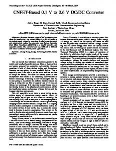
Figs. 21 and 22, respectively. This topology needs magnetics as high as 43.56% of the drive rating. There is a need for a suitable ac–dc converter which has the same dc-link voltage as that of a six-pulse diode bridge rectifier (for retrofit applications) and which needs small magnetics. 2) Proposed Harmonic Mitigator: The supply current waveform at full load along with its harmonic spectrum is shown in Fig. 23 (Topology “D”), which shows that the THD of the ac mains current is 8.17% and the power factor obtained is 0.975. Fig. 24 shows the supply current waveform along with its harmonic spectrum under light load condition (20%). At light load condition, the THD of the ac mains current is 9.40% and the power factor is 0.969. To improve the power-quality indices further, a passive shunt filter has been connected at the supply input (Topology “E”). Fig. 25 shows the dynamic performance of the proposed harmonic mitigator (Topology “E”) at starting and load perturbation. Fig. 26 shows the supply current waveform along with its harmonic spectrum at full load condition, showing a THD of 6.68% and a power factor of 0.982. The supply current waveform under light load condition
1490
Fig. 25. Dynamic response of proposed 12-pulse autotransformer-based ac-dc converter-fed VCIMD with load perturbation for Topology “E.”
IEEE TRANSACTIONS ON POWER DELIVERY, VOL. 21, NO. 3, JULY 2006
Fig. 27. AC mains current waveform along with its harmonic spectrum at light load (20%) for Topology “E.”
TABLE I POWER-QUALITY INDICES UNDER VARYING LOADS HARMONIC MITIGATOR-FED VCIMD
IN
PROPOSED
TABLE II COMPARISON OF SUPPLY CURRENT AND CONVERTER INPUT CURRENT IN DIFFERENT CONVERTERS
Fig. 26. AC mains current waveform along with its harmonic spectrum at full load for Topology “E.”
(20%), along with its harmonic spectrum, is shown in Fig. 27, which shows that the THD of the ac mains current is 7.52% and the power factor is 0.98. Table I shows the effect of load variation on the VCIMD to study various power-quality indices. It shows that the proposed harmonic mitigator is able to perform satisfactorily under load variation on VCIMD with almost unity power factor (always higher than 0.98) and a THD of supply current always less than 8%. This is within the IEEE Standard 519 [11] limits for SCR 20. Table II shows the variation of supply current and conwith a load on VCIMD. It can be obverter input current is always less than the conserved that the supply current verter input current . The variation of THD of the ac mains current and power factor in VCIMD fed from a six-pulse and the proposed 12-pulse ac–dc converters is shown in Figs. 28 and 29, respectively, showing a remarkable improvement in these power-quality indices. Table III shows a comparative study
of different power-quality indices of a VCIMD fed from a six-pulse converter and different 12-pulse converters. The converters in topologies A and B result in a higher dc-link voltage than a six-pulse diode bridge rectifier. So these topologies cannot be used in retrofit applications. The autotransformer in Topology “C” results in a dc-link voltage that is almost the same as that of a six-pulse diode bridge rectifier, but the rating of the magnetics is high 20.825 kVA (43.56% of the drive rating), which is on a higher side as shown in Table IV. The proposed autotransformer-based 12-pulse ac–dc converter gives the same dc-link voltage as that of a six-pulse diode bridge rectifier, making it suitable for retrofit applications. Moreover, the rating of the autotransformer is 9.3 kVA. It needs
SINGH et al.: HARMONIC MITIGATION USING CONVERTER IN MOTOR DRIVES
1491
TABLE III COMPARISON OF POWER-QUALITY PARAMETERS OF A VCIMD FED FROM DIFFERENT 12-PULSE CONVERTERS
Fig. 28. Variation of THD of the ac mains current with load on VCIMD in six-pulse and proposed 12-pulse ac-dc converter- (Topology “E”) fed VCIMD.
proposed converter has shown the flexibility to design the transformer suitable for retrofit applications with variable frequency induction motor drives operating under varying load conditions. The proposed harmonic mitigator has resulted in the reduction in rating of the magnetics, leading to the saving in overall cost of the drive. The effect of load variation on the VCIMD on various power-quality indices has also shown the efficacy of the proposed harmonic mitigator in improving these indices. The observed performance of the proposed harmonic mitigator has been found better than the existing 12-pulse converter configurations. The performance of the proposed harmonic mitigator has demonstrated the capability of this converter resulting in the improvement of power-quality indices at the ac mains in terms of the THD of the supply current, THD of supply voltage, power factor, and crest factor. On the dc-link side too, it provides a remarkable improvement in ripple factor of the dc-link voltage. It can easily replace the existing six-pulse converters without much alteration in the existing system layout and equipment. APPENDIX MOTOR AND CONTROLLER SPECIFICATIONS
Fig. 29. Variation of power factor with load on VCIMD in six-pulse and proposed 12-pulse ac–dc converter- (Topology “E”’) fed VCIMD.
TABLE IV RATING OF MAGNETICS IN DIFFERENT CONVERTER TOPOLOGIES
50 HP Three-phase squirrel cage induction motor (37.3 kW), three-phase, four-Pole, Y-connected, 460 V, 60 , , , Hz, , , - . Controller parameters , ; PI controller: mH, F. DC-link parameters: Magnetics ratings Twelve-pulse-based converter: Autotransformer rating 9.3 kVA, interphase transformer 1.38 kVA, passive filter 2.22 kVA. REFERENCES
a small rating interphase transformer of 1.38 kVA, resulting in total magnetics of 10.68 kVA (22.34% of drive rating). VII. CONCLUSION A novel autotransformer-based 12-pulse ac–dc converter has been modeled with a VCIMD load. The design technique of the
[1] P. Vas, Sensorless Vector and Direct Torque Control. Oxford, U.K.: Oxford Univ. Press, 1998. [2] D. A. Paice, Power Electronic Converter Harmonics: Multipulse Methods for Clean Power. Piscataway, NJ: IEEE Press, 1996. [3] S. Choi, P. N. Enjeti, and I. J. Pitel, “Polyphase transformer arrangements with reduced kVA capacities for harmonic current reduction in rectifier type utility interface,” IEEE Trans. Power Electron., vol. 11, no. 5, pp. 680–689, Sep. 1996. [4] D. A. Paice, “Multipulse converter system,” U.S. Patent 4 876 634, Oct. 24, 1989. [5] P. W. Hammond, “Autotransformer,” U.S. Patent no. 5 619 407, Apr. 8, 1997. [6] D. A. Paice, “Transformers for Multipulse AC/DC Converters,” U.S. Patent no. 6 101 113, Aug. 8, 2000.
1492
[7] S. Hansen, U. Borup, and F. Blaabjerg, “Quasi 12-pulse rectifier for adjustable speed drives,” in Proc. IEEE APEC Conf., 2001, pp. 806–812. [8] G. R. Kamath, B. Runyan, and R. Wood, “A compact autotransformer based 12-pulse rectifier circuit,” in Proc. IEEE IECON Conf., 2001, pp. 1344–1349. [9] IEEE Guide for Application and Specification of Harmonic Filters, IEEE Std. 1573, 2003. [10] D. A. Gongalez and J. C. Mccall, “Design of filters to reduce harmonic distortion in industrial power systems,” IEEE Trans. Ind. Appl., vol. IA-23, no. 3, pp. 504–511, May/Jun. 1987. [11] IEEE Guide for Harmonic Control and Reactive Compensation of Static Power Converters, IEEE Std. 519-1992.
Bhim Singh (SM’99) was born in Rahamapur, India, in 1956. He received the B.E. (electrical) degree from the University of Roorkee, Roorkee, India, in 1977 and the M. Tech. and Ph.D. degrees from the Indian Institute of Technology (IIT), Delhi, New Delhi, India, in 1979 and 1983, respectively. In 1983, he joined the Department of Electrical Engineering, University of Roorkee, as a Lecturer, and in 1988 became a Reader. In December 1990, he joined the Department of Electrical Engineering, IIT Delhi, as an Assistant Professor. He became an Associate Professor in 1994 and a full Professor in 1997. His field of interest includes power electronics, electrical machines and drives, active filters, static VAR compensator, and analysis and digital control of electrical machines. Dr. Singh is a Fellow of Indian National Academy of Engineering (INAE), the Institution of Engineers (India) [IE (I)], and the Institution of Electronics and Telecommunication Engineers (IETE), a Life Member of the Indian Society for Technical Education (ISTE), the System Society of India (SSI), and the National Institution of Quality and Reliability (NIQR).
IEEE TRANSACTIONS ON POWER DELIVERY, VOL. 21, NO. 3, JULY 2006
G. Bhuvaneswari (SM’99) received the M.Tech. and Ph.D. degrees from the Indian Institute of Technology (IIT), Madras, India, in 1988 and 1992, respectively. Currently, she is an Assistant Professor, Department of Electrical Engineering, IIT Delhi, New Delhi, India, where she has been since 1997. Her research interests include power electronics, electrical machines, and power conditioning. She is a fellow of IETE.
Vipin Garg (M’05) was born in Kurushhetra, Haryana, India, in 1972. He received the B.Tech. (Electrical) and M.Tech. degrees from Regional Engineering College, Kurukshetra, in 1994 and 1996, respectively, and is currently pursuing the Ph.D. degree at the Indian Institute of Technology Delhi, New Delhi. He joined the Indian Railways Service of Electrical Engineers (IRSEE), New Delhi, as an Assistant Electrical Engineer and became Divisional Electrical Engineer in 2002. His research interests include power electronics and electric traction and drives.