IEEE TRANSACTIONS ON POWER ELECTRONICS, VOL. 12, NO. 6, NOVEMBER 1997. 971. Inverter Harmonic Reduction Using Walsh. Function Harmonic ...
IEEE TRANSACTIONS ON POWER ELECTRONICS, VOL. 12, NO. 6, NOVEMBER 1997
971
Inverter Harmonic Reduction Using Walsh Function Harmonic Elimination Method Tsorng-Juu Liang, Member, IEEE, Robert M. O’Connell, and Richard G. Hoft, Life Fellow, IEEE
Abstract—A pulse-width-modulated (PWM) inverter using the Walsh function harmonic elimination method is proposed in this paper. By using the Walsh domain waveform analytic technique, the harmonic amplitudes of the inverter output voltage can be expressed as functions of switching angles. Thus, the switching angles are optimized by solving linear algebraic equations instead of solving nonlinear transcendental equations. The local piecewise linear relations between the switching angles and the fundamental amplitude can be obtained under an appropriate initial condition. By searching all feasible initial conditions, the global solutions are obtained. The relations between switching angles and fundamental amplitude can be approximated by straight-line curve fitting. Thus, on-line control of fundamental amplitude and frequency is possible for the microcomputerbased implementation. The developed algorithm can be applied to both bipolar and unipolar switching schemes. The theoretical predictions are confirmed by computer simulations and DSPbased hardware implementation. Index Terms— Harmonic elimination, inverter, pulse-width modulation, Walsh function.
I. INTRODUCTION
T
HE OBJECT of the dc/ac inverter is to produce a sinusoidal ac voltage with controllable magnitude and frequency. Inverters are widely used in many applications such as in the UPS and ac motor drives. There are many types of inverters. The pulse-width-modulated (PWM) inverter is the most favored one for industrial applications. The control schemes of PWM inverters are broadly classified as programmed PWM inverters and sinusoidal PWM inverters. The sinusoidal PWM method is very popular in many applications. However, this scheme is not suitable for microprocessorbased implementation when various sinusoidal voltages and frequencies are required in the system. The Walsh function harmonic elimination method was first introduced by Asumadu [1]. This method is not very efficient when a large number of low-order harmonics need to be eliminated. By using the Walsh function analytic technique, the harmonic amplitude can be expressed directly as a function of switching angles [2], [3]. Then, linear algebraic equations are solved to obtain the switching angles resulting in eliminating the unwanted harmonics. The global solution is found by searching all possible switching patterns since the Manuscript received August 31, 1993; revised February 14, 1997. Recommended by Associate Editor, K. D. T. Ngo. T.-J. Liang is with Kaohsiung Polytechnic Institute, Fengshan, Kaohsiung, Taiwan, R.O.C. R. M. O’Connell and R. G. Hoft are with the Department of Electrical Engineering, University of Missouri, Columbia, MO 65211 USA. Publisher Item Identifier S 0885-8993(97)08078-2.
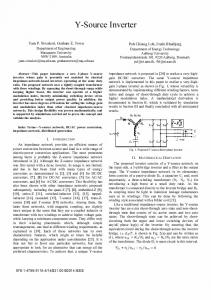
Fig. 1. Power circuit of full-bridge inverter.
local solutions can be obtained only under an appropriate initial condition. A design procedure in which a generalized method is developed for both the bipolar and unipolar voltage schemes is described. The performance of the bipolar and unipolar inverters are compared using the Walsh function harmonic elimination method. By using the linear approximation approach, the switching angles are expressed as linear functions of the fundamental amplitude and frequency. Thus, the switching angles can be computed rapidly on line, and the memory space of the large lookup table that would otherwise be needed is not required. It is also very easy to control the amplitude and frequency of the inverter output voltage for the microcomputer-based implementation. II. WALSH FUNCTION APPROACH The basic circuit configuration of the full-bridge inverter with an – filter is shown in Fig. 1. The full-bridge inverter can provide bipolar voltage switching and unipolar voltage switching. Thus, these two switching schemes are discussed in this paper. A. Bipolar Scheme A typical quarter-period output wave form of the bipolar voltage scheme is shown in Fig. 2 in which one quarter switching intervals. Each switching angle , period has located within the th switching interval, indicates the instant is changed from to in the th switching interval of the quarter cycle. B. Unipolar Scheme A typical quarter-period output waveform for the unipolar voltage switching scheme is shown in Fig. 3 in which switching intervals. Each switching one quarter period has
0885–8993/97$10.00 1997 IEEE
972
IEEE TRANSACTIONS ON POWER ELECTRONICS, VOL. 12, NO. 6, NOVEMBER 1997
Fig. 2. Typical quarter-period output voltage waveform
vinv (t)
of bipolar inverter.
Fig. 3. Typical quarter-period output voltage waveform
vinv (t)
of unipolar inverter.
Fig. 5. Harmonic spectrum for five fundamental amplitudes. Fig. 4. Relation between fundamental amplitude and switching angles.
angle , located within the th switching interval, indicates is changed from zero to in the the instant that th switching interval in the quarter period. The switching are used to eliminate the lower angles order harmonics and control the fundamental amplitude of the inverter output voltage. Walsh functions, one of the class of piecewise constant basis functions, were introduced by Walsh in 1923 [4]. These functions form an ordered set of rectangular waveforms taking only two amplitude values, 1 and 1, over one normalized frequency period. The Walsh functions form a complete or-
thogonal set, hence, Walsh functions can be used to represent signals in the same way as the Fourier series. Generation of the Walsh function series can be carried out in a number of ways [5]–[9]. Sequency-order Walsh functions are chosen at equidistance in this paper. By sampling WAL sampling points (i.e., one normalized period is divided into intervals), the corresponding discrete-time sequency-ordered . form is obtained and designated as WAL Since the sinusoidal waveform has quarter-wave symmetry, have unit it is assumed that the PWM output waveforms amplitude and quarter-wave symmetry. Using Fourier series
LIANG et al.: INVERTER HARMONIC REDUCTION USING WALSH FUNCTION METHOD
(a)
973
(b)
(c) Fig. 6. Bipolar inverter. (a) Solution trajectories. (b) Half-period output waveform with fundamental amplitude Harmonic spectrum.
expansion, the output waveform
A1
= 1:0 per unit (p.u.). (c)
also be used to express the PWM output waveform
can be expressed as
WAL
(1)
as (3)
where where
WAL
(2) However, it is difficult to compute the harmonic amplitudes directly from (2) because the inverter output waveform is unknown. Walsh functions, which have only two amplitudes 1 and 1 over one normalized time period can
of
(4)
is the Walsh coefficient of the inverter output The voltage. Only the order Walsh functions are used because of the quarter-wave symmetry of the inverter output voltage. The greater the number of terms chosen, the smaller the mean-square error between the desired waveform and the actual waveform. The number of terms used in (1) and (3) is based on the required accuracy. Chen and Sun [6] proposed the “dominant-term concept” to choose a sufficient number of the most dominant terms for synthesizing a waveform
974
IEEE TRANSACTIONS ON POWER ELECTRONICS, VOL. 12, NO. 6, NOVEMBER 1997
(a)
(b)
(c) Fig. 7. Unipolar inverter. (a) Solution trajectories. (b) Half-period output waveform with fundamental amplitude
if reasonable error is accepted. This concept is very useful because it saves a great deal of computations when Walsh series are used to analyze inverter output waveforms. By replacing in (2) with (3), the equation becomes WAL
A1
= 1:0 p.u. (c) Harmonic spectrum.
is the harmonic coefficient of the Walsh function. The values of coefficients can be calculated directly from the equation derived by Siemens and Kitai [5]. From (5)
(5) where
WAL
(6) (7)
LIANG et al.: INVERTER HARMONIC REDUCTION USING WALSH FUNCTION METHOD
975
TABLE I LINEAR APPROXIMATION OF SWITCHING ANGLES
Fig. 8. HLF versus fundamental amplitude.
Fig. 9. DF2 versus fundamental amplitude.
calculated from (4). By sampling with equidistant points, the integral in (4) is replaced by a summation Equation (7) in matrix form is
WAL WAL WAL WAL
(8) , the Walsh function By initializing the firing angles coefficients of the PWM output waveforms can be
(9)
, an integer power of two, is determined by the highest sequency-ordered component of the Walsh functions. The value of is always chosen to be equal to , where is given in (3). Since WAL is a constant value ( 1 or 1) in each sampling interval, WAL is replaced
976
IEEE TRANSACTIONS ON POWER ELECTRONICS, VOL. 12, NO. 6, NOVEMBER 1997
by WAL
. Thus, (9) becomes
degrees of freedom are used to eliminate the unwanted harmonic amplitudes harmonics. By setting the selected equal to zero, (14) becomes
WAL WAL .. .
WAL
.. .
.. .
.. .
.. . (15)
(10)
Although the exact values of switching angles are unknown, each of them must be initialized in sampling . So, each switching angle is intervals constrained within the range for
(11)
can be expressed as a function of switching angles [1], [2]. Thus
Equation (15) can be used to analyze a quarter period of the in PWM waveform. By initializing the switching angles sampling interval, the and can be computed and the (15) is solved to compute the switching angles corresponding to the desired fundamental amplitudes under the constraints of the initial conditions. 1) Example (Elimination of 3rd, 5th, and 7th Harmonics in the Bipolar Scheme): It is sufficient to select WAL to evaluate the harmonics up to the 7th harmonic so that one period is divided into 64 sampling intervals (from 0 to 63). An appropriate hypothesis is required to obtain the correct local solution. 1) Case 1: The initialized sampling intervals for the switch, , , and . ing angles are Then, the initial angles in degrees are
(12) where switching angles and matrix form of (12) is
(16)
are the coefficients of the are constants. The From (10) and (14)
(13)
(17)
From (8) and (13) By setting (14) switching angles per quarter period, the degree of Using freedom in (14) is . It is desirable to use one degree of freedom to control the fundamental amplitude, and
, the solutions are
LIANG et al.: INVERTER HARMONIC REDUCTION USING WALSH FUNCTION METHOD
A1
Fig. 10.
Simulation results of bipolar inverter with
Fig. 11.
Experimental results of bipolar inverter with
= 10
A1
p.u. and
:
= 1 0 p.u. :
R
and
and the controllable fundamental amplitude is between represents the fundamental am0.784–1.007, where plitude and the switching angles are calculated in degrees. By searching all possible switching patterns, global linear piecewise solutions are obtained. The solutions for the
977
= 15 .
R
= 15 .
switching angles with the full range of fundamental amplitude are shown in Fig. 4. The harmonic spectrums corresponding to various fundamental amplitudes are shown in Fig. 5. Fig. 5 shows that the 3rd, 5th, and 7th harmonics are almost eliminated.
978
IEEE TRANSACTIONS ON POWER ELECTRONICS, VOL. 12, NO. 6, NOVEMBER 1997
A1
Fig. 12.
Simulation results of unipolar inverter with
Fig. 13.
Experimental results of unipolar inverter with
= 10
A1
p.u. and
:
= 1 0 p.u. :
R
and
III. INVERTER DESIGN WITH BIPOLAR AND UNIPOLAR VOLTAGE SWITCHING The criteria for the inverter design is to minimize the harmonic content of the inverter output since this will reduce the filter size and result in a low-cost high-performance inverter. However, the more harmonics that are eliminated in
= 15 .
R
= 15 .
the preprogrammed PWM inverter, the faster the switching devices must be for the inverter system. Also, it will be more difficult to obtain accurate solutions because of a higher degree of freedom in the equations. It is very practical to eliminate the harmonics up to the 31st so that the lowest harmonic component, which may appear in the inverter output waveform, is the 33rd. Then, the filter size is significantly
LIANG et al.: INVERTER HARMONIC REDUCTION USING WALSH FUNCTION METHOD
A1
Fig. 14.
Experimental results of bipolar inverter with
Fig. 15.
Experimental results of unipolar inverter with
A1
= 06 :
p.u. and
= 0 6 p.u. :
and
reduced, and the switching frequency is not very high (below 4 kHz) so that high-power switching devices [gate turnoff’s (GTO’s) and insulated gate bipolar transistors (IGBT’s)] , the number of switching angles in one can be used. quarter period, is equal to 16 in the inverter. By using a similar procedure to that described in Section II, the switching angles of the bipolar and unipolar switching schemes are optimized. Figs. 6(a) and 7(a) show the solution trajectories versus fundamental amplitude. Figs. 6(b) and 7(b) show the inverter output waveforms. Figs. 6(c) and 7(c) show the harmonic spectra from discrete Fourier transformation (DFT) analysis.
R
R
979
= 15 .
= 15 .
A. Curve-Fitting Method for the Preprogrammed PWM Inverter Usually the preprogrammed PWM inverter is implemented by a microprocessor using a lookup table and saving the switching angles in the memory. But this method has some drawbacks: large memory is needed, and there is less capability for controlling the fundamental amplitude and frequency. The solution trajectories shown in Figs. 6(a) and 7(a) show that the switching angles have a quite linear relationship with the fundamental amplitude. Thus, the switching angles can be expressed as a first-order polynomial of the fundamental
980
IEEE TRANSACTIONS ON POWER ELECTRONICS, VOL. 12, NO. 6, NOVEMBER 1997
A1
Fig. 16.
Experimental results of bipolar inverter with
Fig. 17.
Experimental results of unipolar inverter with
A1
= 06 :
p.u. and
= 0 6 p.u. :
and
amplitude. So degree
s
(18)
where and indicate the fundamental frequency and fundamental amplitude, and are the polynomial coefficients for the switching angle . The linear approximation relationships between the switching angles and the fundamental amplitude for the bipolar and the unipolar schemes are shown and are determined off in Table I. The coefficients line via the Walsh functions harmonic method and straightline curve-fitting method. If the polynomial coefficients
R
R
= 75 .
= 75 .
and are stored in the memory, the switching angles can be computed on line very easily. Equation (18) is very useful in practical applications because it has many advantages in the microprocessor-based implementation. First, a lot of memory can be saved because only a small amount of data is required to be stored in the memory. Second, (18) provides a very fast computation scheme since fewer computation steps are required to obtain the switching angles corresponding to the desired fundamental amplitude. Thus, real-time independent control of fundamental amplitude and fundamental frequency is possible because the switching angles can be determined on line instead of off line. This is very useful for both
LIANG et al.: INVERTER HARMONIC REDUCTION USING WALSH FUNCTION METHOD
the uninterruptible power supply (UPS) and the motor drive system. The harmonic loss factor (HLF) and the second-order distortion factor DF2 also are very useful parameters to evaluate the performance of the inverters. 1) HLF: The HLF, which is proportional to total rms harmonic current, is defined as HLF
(19)
2) Second-Order Distortion Factor DF2: The inverter is generally employed with an – filter between the inverter and the load. The – filter provides harmonic attenuation, which is proportional to the square of the order of the harmonic. Therefore, the distortion factor that represents total harmonic content at the output of a second-order filter is defined as (20)
DF2 where fundamental voltage of inverter output; harmonic voltage of inverter output; order of harmonics.
B. Variation of HLF and DF2 versus Fundamental Amplitude Fig. 8 shows the variations of the HLF versus the fundamental amplitude , and Fig. 9 shows the variations of DF2 versus the fundamental amplitude. Figs. 8 and 9 illustrate that the HLF and DF2 decrease progressively when the fundamental voltage amplitude is increased. Also, the HLF and DF2 of the linear approximation have very small errors compared with those of the exact switching angles. It also can be concluded that the unipolar voltage switching scheme has better performance than that of the bipolar voltage switching scheme. IV. HARDWARE IMPLEMENTATION AND EXPERIMENTAL RESULTS To verify the performance of the inverter, the preprogrammed PWM inverter was implemented with the Texas Instruments TMS320C14 digital signal processor [16]. The high-speed central-processing unit (CPU) of the TMS320C14 computes switching angles accurately resulting in low total harmonic distortion (THD) nearly sinusoidal voltage. The simulations and experiments were carried out with the following circuit parameters: V; mH; uF;
Figs. 10–13 are the computer simulations and experimental results for the bipolar and unipolar inverters with
981
p.u., . Figs. 14–17 are the experimental results with various fundamental amplitudes and load conditions. The results show that high-performance low THD sinusoidal voltage can be obtained with both bipolar and unipolar voltage schemes. V. CONCLUSION This paper proposes a superior scheme for producing nearly sinusoidal output waveforms using the modified Walsh funcswitching tion harmonic elimination method. There are angles to be computed in one quarter period to eliminate harmonics since one degree of freedom is used to determine the fundamental amplitude. Generalized methods are developed to eliminate up to 15 harmonics. The results show that the switching angles computed accurately eliminate the selected harmonics for the desired fundamental amplitudes. The algorithm solves the linear algebraic equations off line to obtain the switching angles corresponding to the fundamental amplitude. By using the curve-fitting method, the switching angles are expressed as linear functions of the fundamental amplitude and fundamental frequency. It is shown that the performance of linear approximation results are very good for practical implementations. It is very easy to generate a variable-frequency variable-voltage sinusoidal voltage in a simple manner because the switching angles can be computed on line very easily. Also, smaller memory is needed, and fewer computations are required for the hardware implementation. Bipolar and unipolar switching patterns are investigated and optimized. The results show that the unipolar inverter is a better scheme since it has the lowest HLF and distortion factor. The high-speed CPU of the TMS320C14 digital signal processor makes the preprogrammed PWM inverter most useful since the switching angles are computed accurately, resulting in precision results. Using filter circuits, the remaining higher order harmonics are relatively easy to filter out, giving a nearly sinusoidal output. The hardware results compare very favorably with computer simulation results. REFERENCES [1] J. A. Asumadu and R. G. Hoft, “Microprocessor-based sinusoidal waveform synthesis using Walsh and related orthogonal functions,” IEEE Trans. Power Electron., vol. 4, no. 2, pp. 234–241, 1989. [2] F. Swift and A. Kamberis, “A new Walsh domain technique of harmonic elimination and voltage control in pulse-width modulated inverters,” IEEE Trans. Power Electron., vol. 8, no. 2, pp. 170–185, 1993. [3] T. J. Liang and R. G. Hoft, “Walsh function method of harmonic elimination,” in IEEE APEC Conf. Rec., 1993, pp. 847–853. [4] J. L. Walsh, “A closed set of orthogonal functions,” Am. J. Math, vol. 55, pp. 5–24, Jan. 1923. [5] K. H. Siemens and R. Kitai, “A nonrecursive equation for the Fourier transform of the Walsh function,” IEEE Trans. Electromagn. Compat., vol. EMC-15, no. 2, pp. 81–83, 1973. [6] B. D. Chen and Y. Y. Sun, “Waveform synthesis via inverse Walsh transform,” Int. J. Electron., vol. 48, no. 3, pp. 243–256, 1980. [7] K. Muniappan and R. Kitai, “Walsh spectrum measurement in natural dyadic and sequency ordering,” IEEE Trans. Electromagn. Compat., vol. EMC-24, pp. 46–49, Feb. 1982. [8] K. G. Beauchamp, Walsh Functions and Their Applications. New York: Academic, 1977. [9] K. G. Beachamp, Applications of Walsh Functions and Related Functions. New York: Academic, 1984.
982
IEEE TRANSACTIONS ON POWER ELECTRONICS, VOL. 12, NO. 6, NOVEMBER 1997
[10] H. S. Patel and R. G. Hoft, “Generalized technique of harmonic elimination and voltage control in thyristor inverter,” IEEE Trans. Ind. Applicat., vol. IA-16, pp. 310–317, May/June 1973. [11] P. N. Enjeti, P. D. Ziogas, and J. F. Lindsay, “Programmed PWM techniques to eliminate harmonics: A critical evaluation,” IEEE Trans. Ind. Applicat., vol. 26, no. 2, pp. 302–316, 1990. [12] I. J. Pitel, S. N. Taluckdar, and P. Wood, “Characterization of programmed-waveform pulsewidth modulation,” IEEE Trans. Ind. Applicat., vol. IA-16, no. 5, pp. 707–715, 1980. [13] A. Kawamura and R. G. Hoft, “Instantaneous feedback controlled PWM inverter with adaptive hysteresis,” IEEE Trans. Ind. Applicat., vol. IA20, no. 4, pp. 769–775, 1984. [14] S. R. Bowes, “New sinusoidal pulsewidth modulated inverter,” Proc. Inst. Elect. Eng., vol. 122, no. 11, pp. 1279–1285, 1975. [15] J. W. A. Wilson and J. A. Yeamans, “Intrinsic harmonic of idealized inverter PWM system,” in IEEE IAS Annu. Meet., 1976, pp. 967–973. [16] Texas Instruments, “TMS320C14 User’s Guide,” Houston, TX 1988.
Tsorng-Juu Liang (M’93) was born in Kaohsiung, Taiwan, R.O.C. He received the B.S. degree in electrophysics from National Chiao-Tung University, Hsinchu, Taiwan, in 1985. He received the M.S. and Ph.D. degrees in electrical engineering from the University of Missouri, Columbia, in 1990 and 1993, respectively. From June 1987 to May 1989, he was employed as a Research and Design Engineer at TECO Electric and Machinery Company, Taiwan, working on switching-mode power-supply design. From 1990 to 1993, he was a Research Assistant in the Power Electronics Research Center, University of Missouri. In 1993, he joined the Kaohsiung Polytechnic Institute as an Associate Professor of Electrical Engineering. His research interests are in the fields of power electronics such as inverters, UPS’s, electronic ballasts, resonant converters, and power factor correction.
Robert M. O’Connell received the B.E. degree in electrical engineering from Manhattan College, Bronx, NY, in 1971 and the M.S. and Ph.D. degrees in electrical engineering from the University of Illinois, Urbana, in 1972 and 1975, respectively. From 1975 through 1979, he served as a Research Electronic Engineer in the U.S. Air Force. In 1980, he joined the University of Missouri, Columbia, where he is presently an Associate Professor of Electrical Engineering and Director of the Power Electronics Research Center. His technical interests are in power semiconductors, power electronic converters, power system harmonics and compensation, and power electronics curriculum development. Dr. O’Connell is a Member of Eta Kappa Nu, Tau Beta Phi, and the IEEE Power Electronics and Education Societies.
Richard G. Hoft (M’52–SM’58–F’80–LF’92) received the B.S.E.E. degree from Iowa State University, Ames, in 1948, the M.E.E. degree from the Rensselaer Polytechnic Institute, Troy, NY, in 1954, and the Ph.D. degree from Iowa State University, Ames, in 1965. He joined General Electric, Schenectady, NY, as a Test Engineer in 1948. From 1949 to 1956, he was a Development Engineer in the General Electric General Engineering Laboratory. From 1956 to 1960, he served as a Manager, Electrical Control Engineering, General Engineering Laboratory. The scope of his unit was changed in 1960 as was the name of the laboratory, and he served as Manager, Converter Circuits Engineering, Advanced Technology Laboratories, General Electric, from 1960 to 1963. In 1963, he took a leave of absence from General Electric and returned to Iowa State University to earn the Ph.D degree. He then joined the University of Missouri, Columbia, as an Associate Professor of Electrical Engineering. He was appointed Professor of Electrical Engineering in 1968 and continued in that position until his retirement in 1993. He was a Doctoral Dissertation Supervisor for 38 Ph.D. students. He has written three textbooks on power electronics and is the author and/or coauthor of more than 100 technical papers on power electronics. Dr. Hoft was the first recipient of the IEEE William E. Newell Award for Outstanding Achievement in Power Electronics in 1977. He received the 1984 Byler Distinguished Professor Award in recognition of his outstanding abilities, performance, and character from the University of Missouri. He has been very active in the IEEE throughout his career and has served as Editor of the IEEE TRANSACTIONS ON POWER ELECTRONICS since 1990.