This article appeared in a journal published by Elsevier. The attached copy is furnished to the author for internal non-commercial research and education use, including for instruction at the authors institution and sharing with colleagues. Other uses, including reproduction and distribution, or selling or licensing copies, or posting to personal, institutional or third party websites are prohibited. In most cases authors are permitted to post their version of the article (e.g. in Word or Tex form) to their personal website or institutional repository. Authors requiring further information regarding Elsevier’s archiving and manuscript policies are encouraged to visit: http://www.elsevier.com/copyright
Author's personal copy
Information and Software Technology 52 (2010) 492–505
Contents lists available at ScienceDirect
Information and Software Technology journal homepage: www.elsevier.com/locate/infsof
HCI and business practices in a collaborative method for augmented reality systems Guillaume Godet-Bar *, Dominique Rieu, Sophie Dupuy-Chessa University of Grenoble, CNRS, LIG, 681, rue de la Passerelle – BP 72, 38402 St. Martin d’Hères, France
a r t i c l e
i n f o
Article history: Received 16 November 2008 Received in revised form 21 November 2009 Accepted 21 November 2009 Available online 27 November 2009 Keywords: Information systems Software engineering Human–computer interaction Augmented reality Collaborative design Evolution
a b s t r a c t Context: Every interactive system is composed of a functional core and a user interface. However, the software engineering (SE) and human–computer interaction (HCI) communities do not share the same methods, models or tools. This usually induces a large work overhead when specialists from the two domains try to connect their applicative studies, especially when developing augmented reality systems that feature complex interaction cores. Objective: We present in this paper the essential activities and concepts of a development method integrating the SE and HCI development practices, from the specifications down to the design, as well as their application on a case study. Method: The efficiency of the method was tested in a qualitative study involving four pairs of SE and HCI experts in the design of an application for which an augmented reality interaction would provide better user performance than a classic interactive system. The effectivity of the method was evaluated in a qualitative study comparing the quality of three implementations of the same application fragment (based on the same analysis model), using software engineering metrics. Results: The first evaluation confirmed the ease of use of our method and the relevance of our tools for guiding the design process, but raised concerns on the handling of conflicting collaborative activities. The second evaluation gave indications that the structure of the analysis model facilitates the implementation of quality software (in terms of coupling, stability and complexity). Conclusion: It is concluded that our method enables design teams with different backgrounds in application development to collaborate for integrating augmented reality applications with information systems. Areas of improvement are also described. ! 2009 Elsevier B.V. All rights reserved.
1. Introduction The evolution of development methods and software complexity has progressively forced designers to specialize in specific domains. In particular, the range of necessary competences and models for designing and implementing applications has widened over the years. This has sometimes led specialists from different domains, for instance human–computer interaction, to design the same application from a totally different point of view from one another, and therefore explore aspects of the future system that are sometimes unforeseen from a purely ‘‘functional core side”. Consequently, before versions of the UML language started proposing profiling for different domains, specialists have filled the vacuum by elaborating their own languages. For instance, the human–computer interaction domain features formalisms such as CTT [1] or MAD [2], and design processes such as CAMELEON-RT [3]. As a consequence, SE and HCI specifications vary in terms of concerns addressed, practices adopted for managing these con* Corresponding author. Tel.: +33 678787954. E-mail addresses:
[email protected] (G. Godet-Bar), Dominique.
[email protected] (D. Rieu),
[email protected] (S. Dupuy-Chessa). 0950-5849/$ - see front matter ! 2009 Elsevier B.V. All rights reserved. doi:10.1016/j.infsof.2009.11.007
cerns, languages used for modeling solutions and tools. Despite the existing methods and processes for integrating user concerns into the development cycle (User-Centered Design, as described by the ISO 13407, or Usage-Centered Design, as described by Constantine et al. [13]), the state of practice in most organisations feature leaves these differences in specifications all too often unresolved. Several factors may explain this situation: when involved in the development cycle, HCI specialists are implicated too far down the development lifecycle, there is a lack of compatibility between methods for designing the interaction and the functional core, as well as a lack of collaborations between software engineering (SE) and HCI specialists. As a consequence, applications are still mainly a product of functions-centered development, and the choices made in terms of interaction, even though they are directly related with the way the end user experiences the system, have virtually no impact on the design of its functionality. This problem is magnified when considering augmented reality applications. These systems comprise any interactive system that superimposes virtual data onto the real world. Amongst their numerous assets, these systems give out opportunities for increased usability: they are more intuitive because they allow users to interact using gestures, vocal commands, with a combination of
Author's personal copy
G. Godet-Bar et al. / Information and Software Technology 52 (2010) 492–505
virtual and real entities. The development of these systems both requires specific processes [4] and models, such as ASUR [5] or IRVO [6]. Consequently, new efforts for integrating SE and HCI practices need to be undertaken. In fact, we believe that it is clearly indispensable to take into account the choices of interaction while designing the system’s functionality, as early as possible in the development cycle. From this perspective, one of the inevitable question that arises is whether the early design of the interaction, especially for augmented reality interfaces, has an influence on the design choices for the software engineering and business aspects. In order to address these issues, we have proposed a set of essential principles for constructing a method integrating both the practices of the SE and HCI domains. We have realized an adaptation of the Symphony development method [7] as a medium for applying these principles. While this method is originally software engineering oriented and focuses on the design of the functional core and business aspects of the system, we have integrated HCI practices and models for designing classic interfaces and augmented reality ones. Additionally, this method allows us to take into account the influence of the HCI design choices on the functional core of the future system, up to the business definition level. In concrete terms, we added the following to the original Symphony method: ! activities involving usability experts and HCI specialists, ! a collaboration mechanism for allowing the different actors of the method to produce common artifacts, ! an HCI specification sub-process, realized in parallel to the specification of the functionality, ! an original specification and analysis model: the Interactional Objects, used for structuring and organizing the interaction space, ! a specific relationship, called ‘‘Represent”, for connecting the business space (modelled using Business Objects) with the interaction space, ! a specific analysis entity: the Translation class, which manages the translation of interaction event semantics into business space semantics, ! a collaborative sub-process for managing business space evolution opportunities, based on the HCI specification. We detail in the next section the major works on the integration of HCI concerns in methodologies. We summarize in Section 3 the essential principles on which our augmentation of the Symphony method is based. We detail both the case study and its development using the Symphony method, focusing on the specifications phases, in Section 4. Then, Section 5 describes the principles for envisaging business evolution, from the bottom-most levels of refinement up to the definition of the business managed by the information system. Section 6 carries on with the development of the case study at the analysis level, and Section 7 presents our results and a discussion issued from empirical experiments on the acceptance of our method. We finally conclude this paper by giving some perspectives on future works.
2. Related work Classical software engineering methods seldom put an emphasis on the design of the human–computer interaction. For instance, the Rational Unified Process [8] only mentions UI design in the requirements discipline, as a single prototyping activity. Amongst the works explicitly addressing the merging of HCI and SE practices, we have come across two types of approaches. On the one hand, contributions such as UPi [9] or DIANE+ [10] propose extensions of existing methods (the Rational Unified Process
493
[8] or MERISE – a development method mostly used in francophone companies) that address specifically user interface design. In terms of actors, these methods involve HCI and/or usability experts, but to the best knowledge of the authors, while UPi is described as a RUP discipline, no indications on how DIANE+ should be integrated into its host method is given. Additionally, while UPi has been used for developing government applications in Brasil, there is no clear evidence of DIANE+ being used outside of the academic world. On the other hand, works by Nunes [11] on the Wisdom method and by Roberts [12] on User Engineering focus on integrating HCI modelling practice (such as task modelling) into UML driven, user-centered methods, thus facilitating its adoption by software engineers. Contrary to the previous methods, these processes do not involve HCI and/or usability experts. Additionally, both methods have been used in an industrial context: Wisdom has been applied in small SE companies (which is the scope of the method), while User Engineering has been used at IBM since its first versions in the 1980s as ‘‘Ovid”. Despite their differing visions of development, the methodologies we have studied put the same strong emphasis on the identification of the users’ expectations as a starting point for the system specifications. This approach is notably advocated by Constantine et al. [13] as ‘‘usage-centered development”, which consists in describing use cases of a higher level of abstraction (i.e., ‘‘essential use cases”) that focus on the intentions of the users (i.e., what they value) rather than on technical implementations and system behaviour. Centering development on the user has also been a recommendation of the reports from the Standish group, as of 1995 [14], which recommend integrating users or user proxies as commited members of development teams. These concerns have eventually crystallized into lightweight, user-centered methods such as Agile [15,16]. However, these approaches focus on development teams with some level of technical and theoretical experience, which is still scarce in the industry when considering mixed reality systems. Therefore, our assumption is that development teams engaged in the design of these types of systems will need to tackle the technological complexity of these systems, as well as the usability challenges they pose. This may be achieved by documenting design choices more thoroughly, which allows tracing decisions from the requirements to the code and identifying the impact of requirements changes more easily. Additionally, the methods we studied (and most recent methods, in fact) adopt iterative and incremental processes, which account for the ontological instability of requirements [14]. Some of these methods also provide mechanisms for adapting the process to the development context, i.e., the project’s complexity and technological risk, the cumulated experience of the development team, etc. Thus, RUP [8] uses iteration plans for managing the development context, in terms of the time spent realizing and iterating over each phase. The Wisdom method [11] extends this concept by providing an adaptive process, based on an ‘‘improvement strategy”: development teams may adopt practices from the method progressively, with respect to their needs in terms of development process formalization and iteration management. In the following section, we present how the above analysis enabled us to formulate essential principles for engineering our own development method. Additional details on our analysis are also provided for each principle.
3. Principles and method We present in this section the essential principles for constructing a method adapted to the problematics related to the design of
Author's personal copy
494
G. Godet-Bar et al. / Information and Software Technology 52 (2010) 492–505
augmented reality systems, and the method we have chosen as a medium for applying these principles: the Symphony method. 3.1. Essential principles The structure of a method is defined by four inseparable and complementary components [17]: process(es) guiding the development activities, models representing facets of the system, languages (from which models are constructed), and tools or techniques for allowing and facilitating the use and setup of processes, models and languages. By taking into account these four components, how may we build a design method for augmented reality systems? On which components may we base our method? All the works that we studied and that have had an application in the industrial world are based on processes from the SE community. We adopted the same point of view, which allows capitalizing on well-used and mastered method, whose assets and flaws are well-known. Based on this SE core, we needed to blend in the concerns, models and practices of the HCI domain, in order to address the design of augmented reality systems. Additionally, our approach requires that the design of the HCI be more proactive towards users. Indeed, the chances are that most users are unfamiliar with innovative interfaces. In classic user-centered design, where users are involved in describing how the system should be represented, this bias is likely to result in a marked tendency towards WIMP-like (i.e., classical, form-based) user interfaces. Therefore, we adopted a usage-centered approach [13], where the first involvement of users in the development process is for providing a textual description of the functional tasks they intend to carry out with the system. After that, a first iteration of HCI design is performed on this description – featuring augmented reality interaction, where applicable – before it is evaluated by users. Then, we constructed our method on the following principles: Seamless integration of SE and HCI practices. The methods we have studied suppose that all actors share the same system development background. However, blending in HCI and SE practices should involve experts from both domains. However, this change of development paradigm should not cause a revolution in development practices. In particular, HCI as well as SE processes, models and tools should be preserved, Collaborative design activities. In order to enable actors from different domains to work together, we should set up collaborative development activities, for allowing synchronizations on common goals and/or models, Traceable and consistent models for collaboration and communication. Methods such as RUP, Wisdom or User Engineering describe the high-level specifications of the system in languages that should enable straightforward communication with end-users and stakeholders. The requirements expressed at this level should be traced down to the implementation code. Additionally, in order to enable collaborations between HCI and SE experts, consensual, non-invasive modeling practices need to be set up. All the models built outside of collaboration activities should convey a consistent view of the system between the domains, Pervasive tooling support. Following Roberts [12], Nunes [11], and the reports from the Standish group [14], our methodology should be supported by a large variety of tools, from planning software and methodological guides, down to code generation toolkits. In particular, these tools should support the preceding principles. We provide below some insight on some of the key features of the first three principles that are illustrated in this paper, which
concern the processes, languages and models aspects of our methodology. 3.1.1. Seamless integration of SE and HCI practices The first principle we mean to apply requires defining clear development problematics, which will be addressed by the adequate development actors: ! The business expert is responsible for identifying the requirements and constraints of the business domain. ! The SE specialist essentially works on functional design issues. ! The usability expert possesses knowledge in the social psychology, visual design, cognitive psychology, but lacks software notions on HCI development issues. Her contribution to the development process is focused on user study and HCI evaluation. ! The HCI specialist is a ‘‘software person” specialized in HCI design from a software perspective and has notions in software usability. Of course, the functional roles being abstract personas, an actor may assume at one point an HCI specialist role before that of a usability expert. In fact, the actors that effectively intervene in the development correspond to instantiations and specializations of these functional roles. 3.1.2. Collaborative design activities Like most development methods, several collaborations between specialists occur for synchronizing points of view, establishing conceptual links between models or taking collegial decisions on design choices. In most cases, these collaborations take place in an informal manner, leaving out the details of the synchronizations between specialists to the project manager’s wild guesses. All of the development activities (including collaborative activities) act as artifact producers and consumers. Following the collaborative activities ontology proposed by Grebici et al. [18], as well as our second principle, joint endeavours are restricted to cooperations. A cooperation consists in defining a common action for different actors, who share, at least partially, a common goal (and product) and organize their actions independently. Specialists filling different headings in a common form are for instance realizing a cooperation activity. 3.1.3. Traceable and consistent models for collaboration and communication Development methods generally integrate models that enable the development team to communicate with users and stakeholders. UML use cases are devoted to this task in RUP [8], whereas Wisdom uses a modified version of the Bridge method’s requirements modeling as ‘‘task flows” [19], User Engineering [12] models goals and tasks using simple UML class diagrams. Also, prototypes are a recurrent model for supporting communications, shared by both HCI and SE traditions [20]. Considering our methodology, our goal was to enable communications both between the development teams and stakeholders, but also between team members with different design cultures. We chose to employ scenarios as described by Carroll [21] for capturing high-level requirements, similarly to Constantine’s ‘‘essential use cases” [13]. Moreover, the practice of describing scenarios has been recognized as one area of convergence between HCI and SE [20], similarly to prototyping. However, these high-level models are not adapted to the mapping of concepts that are close to the implementation code. In particular, SE and HCI experts should be able to easily map the components and services they specified with one another. In order
Author's personal copy
G. Godet-Bar et al. / Information and Software Technology 52 (2010) 492–505
to achieve this goal, our method models business and interaction concepts as ‘‘Symphony Objects”, which are first constructed as independent business objects and Interactional Objects, then connected, before being refined into actual components and services. Additionally, all the models built during the development process need to be (1) traceable; (2) consistent between SE and HCI. Traceability allows tracing back design choices from the final source code up to the scenario which requested it. The principle of systematic production/consumption of artifacts facilitates this process. Consistency guarantees that the different views of the system that the specialists work on correspond to the same model of the system. In the next paragraphs, we describe the Symphony method, into which the processes, languages and models previously presented are integrated. 3.2. The Symphony method Symphony is an iterative and incremental, user-oriented, business component-based development process originally proposed by the Umanis company. Even though the purpose of our work is not about choosing an ideal development method, let us mention that it has been compared to other development methods such as Catalysis [22], RUP [8], Select Perspective [23] and Valtech’s 2TUP. In the results of this comparison, Symphony was able to stand out due to the following properties: ! It features a functional, resolutely business component-oriented approach. ! Business components are systematically identified during the description of requirements. ! The traceability of decisions is guaranteed throughout the development process. ! It features an original business component model, based on a tripartite structures named ‘‘Business Objects”.
! The technical (right) branch allows developers to design both the technical and applicative architectures. It also federates all the constraints and technical choices with relation to security, pervasiveness, load balancing . . . ! The central branch integrates the technical and functional branches into the design model, which merges the analysis models with the applicative architecture, and details traceable components. The organization of phases is summarized in Fig. 1. All phases aim at refining models and scenarios outlined in the previous phase. In this paper we shall focus on the functional branch, where SE and HCI-oriented activities are realized in parallel. In the following section, we describe and apply our augmentation of the Symphony method on a case study. Note that this particular run-through of our methodology corresponds to a development cycle with high technological risks. Our method is particularly suited to this type of project, for which it is recommended to construct a precise documentation of the development iterations, especially if the development team is not familiar with either the business context and/or the technologies. ‘‘Easier” projects or expert teams would probably not need that much documentation. 4. Description of the method and development on a case study 4.1. Presentation of the case study We chose to address a well-known problem encountered by real estate agents when making an inventory of fixtures: the scar-
Therefore, the original Symphony method already has constructs for supporting traceability, which is one of our goals. Additionally, the tripartite component model provides an interesting basis for elaborating a consensual model for HCI and SE experts. 3.2.1. History of the method Symphony has already been extended by Hassine et al. [7] to improve the reusability of components, in a by and for reuse approach. Juras et al. [24] envisaged the implication of different development cultures and described collaboration mechanisms between development experts. In [25], we described the principles of a method integrating HCI and business practices for augmented reality systems, focusing on the concept of ‘‘Interactional Object” as counterparts of the already existing Business Objects. Our next concern was to present the principles of business evolution triggered by interaction choices [26]. Finally, we described some aspects of the technical branch, as well as its merging with the analysis models in [27]. Details concerning HCI design were also addressed in the latter paper. 3.2.2. General structure of the method Symphony is organized into three design branches, similarly to 2TUP, into a Y-shaped development cycle. The whole cycle is applied for each functional unit of the system under development (see below): ! The functional (left) branch corresponds to the traditional task of domain and user requirements modelling, independently from technical aspects. This is where our contributions are focused.
495
Fig. 1. Symphony development cycle.
Author's personal copy
496
G. Godet-Bar et al. / Information and Software Technology 52 (2010) 492–505
city of data available to evaluate a house. Indeed, most of real estate business processes feature basic computerization: specifically, details about the damages’ nature and position are in most cases laid out as paper forms and textual descriptions. Such data is often insufficient when the real estate agent needs to evaluate the evolution of a specific damage or wearing out from one occupation to the next, especially when this is a contentious issue between the tenants and the expert or the landholder. The following paragraphs describe the result of the application of the left branch of the Symphony method on this case study. 4.2. Initial conditions of development Before initiating a development iteration, a preliminary study of the business is realized. Its aim is to obtain a functional decomposition of the business as practiced by the client, in order to identify business processes and their participants. A Business Process (BP) is defined here as a sequence of internal activities realized in the studied business domain, whose goal is to provide an observable, measurable result for an individual user. Our inventory of fixtures case study corresponds to a fragment of a larger real-estate management business, into which several business processes can be identified: ‘‘management of tenants”, ‘‘management of landholders”, ‘‘management of inventories of fixtures”. We focus in this paper on the management of inventories of fixtures, which integrates the management of demands and reclamations, the realization of the inventory itself as well as the management of the results gathered (scheduled repairs, estimates, guarantees, . . .). 4.3. Specification of conceptual requirements This phase comprises the description of goals for all BPs identified during the preliminary study. Each BP is studied so as to determine the added value for each actor, as well as the corresponding constraints. They are then described using scenarios and UML sequence diagrams. The scenarios thus enable all the actors of development, as well as users and stakeholders, to acquire the same initial vision of the company organization. Following this description, each BP can be decomposed into sub-processes named Business Process Components (BPC), in order to facilitate their analysis. A BPC can be considered as a functional subset of a BP. In our case study, the ‘‘Manage inventory of fixtures” BP is decomposed into three BPCs: ‘‘Schedule an inventory of fixtures”, ‘‘Realization of an inventory of fixtures”, ‘‘Finalization of an inventory of fixtures” (which consists in treating issues identified during the Inventory of Fixtures, such as compensations for premise deteriorations), as illustrated in Fig. 2. In our extension of the method for the HCI, the usability specialist studies the Business Process as currently practiced by the organization for building a first set of usability prescriptions and choosing a representative set of users for future evaluations. In collaboration with the HCI specialist, the usability expert will determine the types of interactions that may be envisaged for the application, such as augmented reality or classical interfaces. In association with stakeholders and the other experts from the method, they realize an estimation of the added value, cost and risks of development associated to the interaction choice, for each BPC and BP. Considering our example, the ‘‘Realization of an inventory of fixtures” BPC is a good candidate for an augmented reality interaction for a variety of reasons including: ! The case study typically features a situation where the user cannot use a desktop workstation while realizing the activity.
Fig. 2. Business process components of the ‘‘Manage Inventory of Fixtures” Business Process.
! Textual descriptions of damages are both imprecise and tedious to use, especially for describing the evolution of a damage over time and space. ! Several manual activities are required for describing the damages thoroughly, e.g. taking measures, photographs, etc. ! The data gathered during the inventory of fixtures cannot be directly entered into the Information System (except if the user operates a wireless handheld device). ! Standard handheld device such as PDAs would only allow using textual, form-filling approaches, with the aforementioned limitations. 4.4. Specification of organizational and interaction requirements Once the BPs are identified and specified, the specification of organizational and interaction requirements must determine the ‘‘who does what and when” of the future system. The aim of this phase is to consider the conceptual choices and detail the actual behaviour of each BP actor. We have extended this phase to include the specification of the interaction, based on the choices of interaction style made during the previous phase. An essential originality of our method is featured in this phase, where the interaction and business designers elaborate their own vision of the application, using their own design practices, as suggested by Sukaviriya et al. [28]. Therefore, we deliberately promote the construction of two different visions of the final system, both valuable in terms of the aspects they are expected to focus on (for instance, functions for SE specialists, usability for HCI and usability experts). This process is initiated by realizing an organizational decomposition of the previously identified BPs and BPCs into manual and computerized activities. Each activity is assigned to a system actor. 4.4.1. Organizational requirements During this activity, the SE specialist and the business expert cooperate for extracting and organizing use cases from the previsously identified computerized activities (see Fig. 3). By regrouping the different use cases, business experts and SE specialists identify a set of candidate Business Objects, which correspond to the applicative process (Business Object Process, e.g., the realization of the inventory of fixtures) and central concepts of the business (Business Object Entities, e.g., for modeling the concepts of inventory of fixtures and damage). A ‘‘use” dependency
Author's personal copy
G. Godet-Bar et al. / Information and Software Technology 52 (2010) 492–505
Fig. 3. Use cases for the ‘‘Realize inventory of fixtures” Business Process Component.
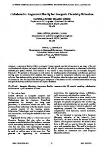
relationship allows organizing Business Objects. Fig. 4 describes the organization of Business Objects pertinent for the development of our case study. 4.4.2. Interaction requirements The interaction requirements make use of the scenarios and usability prescriptions described during the conceptual requirements for designing the HCI. 4.4.2.1. Elaboration of the interaction constituents. Based on the description of the Business Processes, the HCI and usability specialists need to focus on three essential and interdependent aspects of the future interaction: the description of interaction artifacts (see below), of interaction techniques (vocal commands, touch-input interaction), and of the types of devices for supporting the interaction (semi-transparent head-mounted display, touch input mobile device, microphone). The latter activity is optional, as it is only needed for elaborating non-classic interfaces. Given that this part of the process is rather complex and very specific to HCI practices, we focus on the result of these activities, and in particular the following set of interaction artifacts that correspond to the notion of ‘‘damage” identified in the previous phases: ! Photographs of the past states of the damage, superimposed to the actual position of the damage. ! Textual and vocal notes taken during past inventory of fixtures (by other experts, for instance), easily accessible to the expert, for instance using semi-transparent overlays. ! Graphical markers, as cues to identify damage position and size.
fixtures. Therefore, we have added a ‘‘3D Plan” to our list of interaction artifacts, which corresponds to a basic tridimensional model of the premise. During the design of the interaction, concepts that are detached from the business domain may emerge. For instance, in order to allow augmented reality interaction, it is necessary to localize the user in both the physical premise and its digital representation (the 3D plan). We call this projection of the user into the system the ‘‘Avatar”. The interaction techniques are described using dynamic diagrams, in particular user task modeling diagrams such as ConcurTaskTrees [1]. The design of an augmented reality interface requires that developers be able to model the physical and digital elements involved in the interaction, as well as their relationships. Languages such as ASUR [5] provide such constructs, which allow describing the conceptual relationships between physical and digital entities, modalities employed by the user and physical relationships between devices supporting the modalities. In Fig. 5 the user, identified as the expert, is wearing an augmented vision display (‘‘==” relation) which provides information (‘‘–>” relation symbolizes physical or numerical data transfers) about the marker and audio note virtual objects. The mobile device, which includes input and output subsystems, enables the expert to interact with these virtual objects. The marker is a numerical representation (‘‘–>” relation) of a physical damage in the physical world. The expert’s position in the premise is deduced from the positioning subsystem, which sends data for updating the virtual scene (i.e., the 3D plan, and subsequently the marker and audio note virtual objects) as the expert moves. 4.4.2.2. Description of concrete projected scenarios. The descriptions of the artifacts, interaction techniques and devices are integrated into the BP descriptions elaborated during the early specification, in order to obtain concrete scenarios (see Table 1). 4.4.2.3. Iterative prototyping. All along the activities elaborating the interaction of the future system, we recommend constructing software prototypes (presentations, HCI tryouts, . . .) putting into play the products from the specification of the interaction. Beyond the advantage of exploring design solutions, the prototypes allow the usability expert to set up usability evaluations for validating the
Additionally, the plan of the housing is essential for the interaction, in that it allows positioning the user during the inventory of
Fig. 4. Initial Business Objects model.
497
Fig. 5. ASUR diagram of the system.
Author's personal copy
498
G. Godet-Bar et al. / Information and Software Technology 52 (2010) 492–505
Table 1 Excerpt of the concrete projected scenario for the ‘‘Create a damage” task. (. . .) The expert enters into a room. The previous state of the premise is automatically loaded as she enters into the room. It currently displays no prior Damage marker on the Augmented vision device. She walks around the room and notices a dark spot on one of the walls. She creates a new Damage marker and positions, orients and scales it, using the Mobile tactile display so as to be localized precisely on the damage. Next, she locks the marker and attaches an Audio note, using the Microphone.
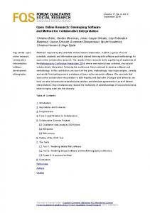
specifications. Fig. 6 shows an early prototype of the interface displayed on the expert’s augmented vision display, using some of the interaction artifacts described above. 4.4.2.4. Usability evaluations. From the different products of the interaction requirements, the usability expert compiles recommendations and rules for the HCI being elaborated, in particular concerning the graphic chart, cultural (language registry, symbols, colors) and physical (use of adequate modalities) constraints. . . Based on the prototypes, the interaction constituents (techniques, artifacts, devices) and the concrete scenarios, the usability expert elaborates validation tests for all the products of the interaction requirements. The interaction requirements are iterated over until all products are validated. Once this is achieved, the HCI Expert may proceed with the description of the Interactional Objects. 4.4.3. Construction of the Interactional Objects model Interactional Objects are used for organizing interaction concepts. Fig. 7 provides a model of the Interactional Objects deduced from the interaction concepts identified previously. The criteria for eliciting an Interactional Object are based on concept granularity and density (i.e. if a concept is anecdotally used or is described by only a few attributes, then it may not be a pertinent choice for an Interactional Object). We focus in this article on the following Interactional Objects: The Marker Entity Objects correspond to the visual cues that will allow experts to localize damages easily (e.g. using red, animated target items). The Audio Note Entity Objects are attached to Marker objects (see Fig. 6 on the right), and represent audio inputs (i.e. vocal notes). The Display Zone Entity Objects will be used to display areas for textual notes, photographs as well as system state data, on the augmented vision display. The Manage 3D Scene Process Object describes the setting up of the augmented reality scene, and carries the rules for managing the different Entity Objects it uses. These Interactional Objects are supposed to help respond to the requirement that the real-estate agency expert be able to compare easily past and present states of the premise (such an interaction
Fig. 7. Interactional Objects model.
would allow continuity of interaction with the physical support, observability of past and present states, immediate feedback, . . .). The last activity of the phase focuses on the connection between Business Objects and Interactional Objects. To this end, we have introduced in the Symphony method a new ‘‘Represent” dependency relationship for realizing this mapping, which was implicit beforehand: one or several Interactional Objects constitute projections in the interaction space of business concepts. However, the description of this relationship may induce business space evolutions. This is what the following section describes. 5. A collaborative activity for envisaging business evolution We explore in this section how the interaction choices made previously by the usability and HCI experts may trigger an evolution of the business space. This exploration occurs from the bottom-most levels of refinement of the specifications up to the business definition level. 5.1. Cooperative model mapping The initial aim of this activity is to describe ‘‘represent” relationships between Interactional Objects and Business Objects. This one-to-many relationship explicitly shows how some business concepts are projected into the interaction space. For example, the notion of damage appears in the interaction space through the notions of ‘‘Marker” and ‘‘Audio Note”. A comparison of the Business Objects model (see Fig. 4) with the Interactional Objects model (see Fig. 7) reveals that interaction
Fig. 6. Early application prototype.
Author's personal copy
G. Godet-Bar et al. / Information and Software Technology 52 (2010) 492–505
concepts feature a different level of granularity than business concepts. For instance, the notion of ‘‘Marker”, which integrates the concepts of location, size, a lifecycle, and a visual representation, is actually more dense than what it is meant to represent (i.e., the notion of ‘‘Damage”, which only contains only attributes related to location (e.g., a room in the premise) and a textual description). Consequently, development actors need to reflect on the necessity to resorb this imbalance in terms of density of services offered. The following paragraphs provide details on the possible evolutions of the business space, induced by interaction choices. We consider the four classic levels of an information system, whose terminology was slightly adapted to the constructs of our method: Business Objects, business activities, Business Processes and business definition. 5.2. Business objects evolution At this level, we evaluate whether the Interactional Objects model manages concerns which could correspond to business responsibilities. Our analysis aims at deciding whether the information system would benefit from transferring and adapting this data to the business space. For instance, augmented reality systems often feature location data (i.e. the 3D plan in our augmented inventory of fixtures), usually used for positioning the user or artifacts in 3D virtual environments superimposed on the physical world. A possible transfer of competences would consist in extending Business Objects competences with the management of architect plans. The ‘‘3D plan” Interactional Object would remain responsible for managing the visual representation of the architect’s plans. Thus in our case study, we could integrate the premises’ plan into the business space (and the information system) using a new ‘‘Housing” Business Object Entity. The final representation of the premise in the augmented reality application would result from a transformation of the plans into 3D coordinates. The concept of housing is not the only one susceptible to undergo transformations caused by choices of interaction. In fact, the notion of ‘‘Damage” is also a rather minimal entity in the basic ‘‘Realize an inventory of fixtures” BP and a much larger one in the Interactional Objects model (i.e. it is represented using Marker and Display Zone Interactional Objects). Once again, integration into the business space of the data featured by these artifacts (i.e. vocal and textual notes, photographs) could prove useful for other Business Processes. However, given the granularity of these information, it is not necessary to split the ‘‘Damage” Business Object Entity into finer entities, therefore we shall integrate them into its current structure. Fig. 8 describes the Business Objects model before and after the coordination activity between the SE and HCI specialists has occurred.
499
Following this evolution, we present in Fig. 9 the final mapping between Business Objects and Interactional Objects, using ‘‘represent” relationships. We show in Section 6 how these relationships are detailed into a full-blown communication model between the business and interaction spaces. 5.3. Business activities evolution We saw in the previous paragraph that these transfers may introduce new attributes and concepts in the business space. Consequently, new activities for collecting, organizing and using this new data may need to be described at the business activity level. From a development process point of view, use cases for carrying these new activities consequently appear, which affect the organization of use cases described during the specification of organizational requirements. Fig. 10 represents an extract of the organization of use cases prior to and following the evolution of the business space. Now that we decided to integrate photographs, vocal and textual notes to the concept of damage in the business space, we need to add a series of use cases for managing these new elements (i.e., for attaching them to the damage). Fig. 10b presents the evolution that the use cases organization underwent in order to make this possible. 5.4. Business Processes’ evolution Driving business evolution to this level means capitalizing on the new use cases introduced at the activity level. In particular, the use of the new data by different (or new) Business Process components and the intervention of new actors, within the
Fig. 9. Excerpt from the Business Objects and Interactional Objects mapping model.
Fig. 8. Partial Business Objects models.
Author's personal copy
500
G. Godet-Bar et al. / Information and Software Technology 52 (2010) 492–505
Fig. 10. Organization of use cases.
information system, may be envisaged. This may enable manual task automatizations or process simplifications. When we consider the use cases added at the activity level for the inventory of fixtures application, we notice that the choice of an augmented reality interaction allows us to have, amongst other things, a greater level of detail for describing the damages. On the other hand, some of the key activities managed by a real-estate agency is the management of repairs for the properties under its responsibility, and the sending of requests for estimates. Now the expert has a direct access to the past states of a damage, as well as the capacity to integrate immediately photographs of its current state into the information system. Consequently, he or she may directly ask for estimates, either by sending data to the agency actors assuming the role of ‘‘repair managers” – and who are now involved in this Business Process, or by communicating details about the damages to the appropriate experts. Fig. 11 shows this evolution of the business space, at the Business Process level.
information system, thus changing the definition of the business. New Business Processes may be added, that will need their own entire iteration of the development process. Consequently, new interaction choices will be made for these new processes and new actors that may also affect the business space. In the context of the inventory of fixtures application, developers and stakeholders may decide to set up new processes for proposing new services, based on the assets provided by the architect’s plan of the premises and the detailed description of damages. For instance, the real-estate agency may propose virtual tours of the premises it manages to future clients. The following section details the last phase of the functional design: the analysis, which takes place once the evolution sub-process is stabilized.
5.5. Evolution of the business definition
This phase describes how the system must behave, more specifically how the Business Objects and Interactional Objects communicate through their ‘‘use” relationships, and how they are structured, in terms of attributes and services. The first aspect is
Beyond reorganizing Business Processes, business evolution may be taken to the point that new services are handled by the
6. Analysis
Fig. 11. Sequence diagrams for the ‘‘Manage inventory of fixtures” Business Process.
Author's personal copy
G. Godet-Bar et al. / Information and Software Technology 52 (2010) 492–505
detailed in a dynamic analysis of the system, while the latter is elaborated in a static analysis. Then, the semantics of the communication between the business and interaction spaces, materialized by the ‘‘represent” relationships, is defined. Besides, note that the technical or architectural aspects of the system are not taken into account at this point. 6.1. Dynamic analysis From the SE specialist’s point of view, the dynamic analysis consists in refining the use cases identified previously into detailed scenarios and sequence diagrams. These descriptions aim at completing the elaboration of Business Objects. The dynamic analysis notably allows identifying the services (i.e. the interface) that these elements must propose. Fig. 12 illustrates the sequence of calls for creating a damage object, from the ‘‘RealizeInvOfFixtures” Business Object Process to the ‘‘InventoryOfFixtures” Business Object Entity, which manages the ‘‘LocalizedDamage” class, which itself creates and sets the position of the actual damage. In this example, the ‘‘Role” classes (i.e., ‘‘ScheduledInventoryOfFixtures” and ‘‘LocalizedDamage”) are used for reducing the depen-
501
dency between the Business Object and its possibly generic collaborators, by concentrating the adaptation into a clearly identified element of the Business Object. In this example, a role class (i.e., ‘‘LocalizedDamage”) is used in order to improve the reusability of the ‘‘Damage” Business Object. Indeed, the semantics of the damage location are specific to the concept of ‘‘Inventory of fixtures”, as it uses the concept of room for placing the damage on the architect’s plan. Transferring all the calls that are linked to the damage’s position in the housing into the ‘‘Inventory of fixtures” Business Object Entity thus allows describing a more generalizable ‘‘Damage” Business Object Entity. From the HCI specialist’s point of view, the dynamic analysis corresponds to the formalization of the Interactional Object’s lifecycle. UML statecharts are used for describing objects with an interesting lifecycle. Additionally, the user task models developed during the interaction specifications are refined into detailed scenarios and sequence diagrams, similarly to the Business Object’s dynamic analysis, for describing the services of the Interactional Objects. Fig. 13 describes the creation of a ‘‘Marker” Interactional Object Entity, through a ‘‘LocalizedMarker” class integrated into the ‘‘Manage3DScene” Interactional Object Process.
Fig. 12. Excerpt from the business space’s dynamic analysis.
Fig. 13. Excerpt from the interaction space’s dynamic analysis.
Author's personal copy
502
G. Godet-Bar et al. / Information and Software Technology 52 (2010) 492–505
6.2. Static analysis During the static analysis, the Symphony Objects partially described during the dynamic analysis must be described as tripartite packages (see Fig. 14). The left part of the package describes the services provided by the object, using an ‘‘Interface” class. The central part of the package describes the implementation of these services (using a ‘‘Master” class), as well as a subdivision of complementary concepts (using ‘‘Part”
classes). Finally, the right part (‘‘Role” classes) describes the services required by the object for guaranteeing its behaviour, from the Symphony Objects they depend on (i.e., there is a ‘‘use” relationship between these Symphony Objects). This conceptualization of the system as a set of independent and interconnected Symphony Objects encourages their modularity and reuse, as well as that of their specifications. Fig. 14 illustrates this organization on two Business Objects (top) and two Interactional Objects (bottom).
Fig. 14. Excerpt from the Symphony Objects static analysis model (business and interaction spaces).
Author's personal copy
G. Godet-Bar et al. / Information and Software Technology 52 (2010) 492–505
6.3. Description of the relationships between the business and interaction spaces At this point, both the business and interaction spaces are exhaustively described, from an implementation–independent point of view. The formalism used for detailing the Symphony Objects is consistent with the concerns of programmer analysts, who intervene in the development process at this point. Now HCI and SE specialists need to detail the ‘‘represent” relationships that were drawn during the specification phases. We saw above that the analysis-level ‘‘use” relationships between Symphony Objects in fact relate ‘‘Role” classes (i.e. the adaptation of a Symphony Object service provider to the applicative concerns of its providee) to ‘‘Interface” classes. Similarly, the analysis-level ‘‘represent” relationships relate ‘‘Role” classes of source Interactional Objects to ‘‘Interface” classes of target Business Objects. For example in Fig. 14, we can see that the ‘‘Damage” and ‘‘Marker” Entity Objects are used respectively by the ‘‘InventoryOfFixtures” Business Object Entity and the ‘‘Manage3DScene” Interactional Object Process through the ‘‘LocalizedDamage” and ‘‘LocalizedMarker” roles. Therefore at the analysis level, the ‘‘represent” dependency relationship is drawn between the ‘‘LocalizedDamage” Role and the ‘‘InventoryOfFixtures” Business Object, which holds the ‘‘LocalizedDamage” Role. It is then necessary to describe the mappings between business and interaction events, as well as translate the interaction concepts into the business referential. For instance, the moving around of a damage marker in the augmented reality scene may modify the attachment of the damage to its corresponding room, depending on the marker’s current position. In this case the position, which is expressed in a tridimensional referential, needs to be translated into an indication that will make sense in terms of the business, for example the reference of the corresponding room in the architect’s plan, saved in the ‘‘Premise” Business Object.
503
The description of the dynamic semantics of the connection between Interactional Objects and Business Objects can be summarized into the following activities: 1. Identification of the Interactional Objects services that may have an impact on the business space (e.g., the ‘‘createMarkerRole” service). We use UML annotations for identifying the methods concerned (see Fig. 15), in the Symphony Objects’ analysis model. 2. Identification of the Business Objects services that need to be called in reaction to the interaction events (e.g., the ‘‘createEntity” service from the ‘‘Damage” Business Object). 3. Identification of the Business Object Process services that will trigger the above event (e.g., the ‘‘createNewDamage” method from the ‘‘RealizeInvOfFixtures” Business Object Process). 4. Description of the translation of the interaction event into a corresponding business event (e.g., we need to translate the pixel coordinates of the marker into a room of the premise), and identification of the translation event (e.g., the ‘‘createMarkerDamage” from the annotation in Fig. 15). Once again, both scenarios and UML sequence diagrams can be used for formalizing this connection, into a form of control class called ‘‘Translation”. Fig. 16 presents an example of a Translation sequence diagram, associated to the creation of a ‘‘Marker” Interactional Object Entity. A Translation has the following properties: ! There is one instance of the Translation class for each instance of paired Interactional Object(s) and Business Object roles. We call the tuple:
c ¼ f½source1 ; source2 ; . . . ; sourcen $; target; translationg
Fig. 15. Example of annotation on a ‘‘Role” class taken from the business space static analysis diagram.
Fig. 16. Translation between the Marker and Damage Symphony Object roles for the ‘‘createMarkerDamage” event.
Author's personal copy
504
G. Godet-Bar et al. / Information and Software Technology 52 (2010) 492–505
a Symphony Connection. Following our example, the connection between a LocalizedMarker and a LocalizedDamage corresponds to the following tuple:
c1 ¼ f½lmarker1 $; ldamage1 ; markerTrans1 g ! Each Translation instance possesses the references to its source (i.e. Interactional Object) and target (i.e., Business Object) elements. For instance, the markerTrans1 Translation instance stores references to the lmarker 1 and ldamage1 objects. ! Each actual translation of an interaction event into a business event is described within a method of the Translation class. Such an event is called a ‘‘connection event”. In our example, the ‘‘createEntity” (called on the ‘‘Marker” Interactional Object, which provides a lmarker1 object) interaction event is translated in a ‘‘createMarkerDamage” method called on the markerTrans1 object. Note that the translation of a connection event is not systematically mapped with a single business event, but may necessitate several calls (for instance, for obtaining the source’s position, creating the target and defining its position). ! If a given Translation instance a from a Symphony Connection c1 obtains a reference to an element from a Symphony Connection c2 , then a may call the services of the translation instance b associated to the Symphony Connection c2 . Thanks to these four properties, the Translation constitutes the only location in the analysis model (and in fine in the implementation code) where interaction and business concepts meet. These properties are sufficiently expressive to cover all the HCI–functional core interactions that the authors have currently met. The following section describes how the different aspects (process and models) and phases of our methodology were evaluated. 7. Empirical evaluation and discussion Even though the original Symphony method appears to have been successfully applied many times in an industrial context, we need to verify that our contributions have benefited the process. Evaluating our methodology involves testing all of its components (process, language, models, and tools), as well as its acceptance and scope. Along this perspective, Moody [29] has designed an evaluation model for different aspects of methods, from actual efficacy (the extent to which the method improves the quality of the results and is easily applicable) to actual usage. Following this model, we have conducted evaluations, focusing on two essential aspects: the final product of the method, in particular, the effectiveness of its implementation code, and its efficiency, that is, whether applying the method naturally enables development actors to build augmented reality systems through our collaborative process. The evaluation of the method’s effectiveness consisted in having different versions of the same software implemented by programmers with different levels of experience, based on the same Symphony Object-based analysis model. The goal of this experiment was to determine whether quality code (as evaluated by classical SE software metrics) could be produced, even though the implementation strategy was not optimal. The results of this experiment tend to show that the process and Symphony Objects models do indeed enable developers to produce modular, reusable, and not overly complex components. We focused the evaluation of the method’s efficiency on the following question: Does the method allow HCI and SE experienced developers to collaborate efficiently? The latter problem may be refined into: (1) Are Symphony Objects a satisfying model
for connecting the business and the interaction spaces? (2) Does the process facilitate the collaboration between actors from the SE and HCI domains? (3) Does the process enable developers to select augmented reality (or post-WIMP) interfaces when the interaction context would make classic interfaces clearly less efficient? A qualitative experiment was conducted for the questions mentioned above: four pairs of experienced developers from the academia (one assuming the roles of SE and business specialist, the other the roles of HCI and usability specialist) were involved in the specification of a collaborative software for planning the setup of congress centres. Each pair proposed its own set of specifications, based on the same stakeholder requirements (the stakeholders being played by this paper’s authors). Participants worked alone for SE or HCI-specific activities and paired off for cooperative activities, for instance for integrating the business and HCI specifications, during a recorded session. An interview was conducted at this point and at the end of the experiment. The analysis of the records and of the interviews show that Symphony Objects are relevant for describing both business and interaction spaces. Additionally, they are considered as a ‘‘good synchronization” means for connecting both spaces, using ‘‘represent” relationships. SE and HCI specialists were enabled to collaborate during the design process: the business and interaction-centered facets of the specification are effectively integrated; however in the current state of the method, collaborative activities lack ‘‘conflict resolution [solutions]”. Finally, the results show that the process successfully guides developers towards choosing augmented reality interaction solutions. Furthermore, this evaluation and past informal ones have suggested that the method may be too heavyweight, with regards to the number of models that is required. This point has led us to cut off several fragments of Symphony which either were redundant or demanded that actors produce unnecessarily verbose artifacts. As a matter of fact, this paper presents an already more lightweight approach to augmented reality systems design, compared to previous works.
8. Conclusion and future works In this paper, we have demonstrated how rich, post-WIMP interfaces, such as augmented reality systems, may be integrated into efficient, business-oriented methods without compromising on either the quality of the functionalities or the system’s usability. Our approach is directed by four core principles, which are: (1) a seamless integration of SE and HCI practices; (2) collaborative design activities; (3) traceable and consistent models for collaboration and communication; and (4) a pervasive tooling support. These principles were detailed and applied to an existing method: Symphony, which was originally developed in an exclusively SE perspective. Following a case study for facilitating the realization of inventories of fixtures, we have described the functional specifications and analysis of the future system. An essential aspect of the functional branch is the identification of Interactional Objects and Business Objects, their refinement, as well as the description of Translation objects, which integrate the dynamic semantics of ‘‘represent” relationships. We have also shown how describing the interaction aspects of a system may affect the design of the business space, when an effort for rationalizing the balance of competences between the two conceptual domains is made. Finally, we presented in this paper some details on the evaluations we are currently running on the different aspects of our methodology. As their results are analyzed, we hope to gain some
Author's personal copy
G. Godet-Bar et al. / Information and Software Technology 52 (2010) 492–505
insight on the effectiveness of the method engineering choices we made. However, several aspects of our methodology were not covered in this paper. In particular, we are developing a large tooling support for (1) documenting the method in order to allow efficiently navigating between activities, alternatives, etc.; (2) automating parts of the development, in particular the development cycle of Symphony Objects, which follows systematic rules; (3) supporting the execution of applications built using the Symphony method: provided that the refinement rules associated with Symphony Objects are respected, strong assumptions can be made concerning the application’s architecture that may be used for transferring parts of the implementation effort onto a framework. On a long-term perspective, we hope to gain the opportunity to confront our contributions to the Symphony method to development projects from the industry, for which it has been designed.
References [1] F. Paterno, ConcurTaskTrees: an engineered notation for task models, in: The Handbook of Task Analysis for Human–Computer Interaction, Lawrence Erlbaum Associates, 2003, pp. 483–503. [2] S. Sebillotte, Methodology guide to task analysis with the goal of extracting relevant characteristics for human–computer interfaces, International Journal of Human–Computer Interaction 7 (4) (1995) 341–363. [3] L. Balme, A. Demeure, N. Barralon, J. Coutaz, G. Calvary, Cameleon-rt: a software architecture reference model for distributed, migratable, and plastic user interfaces, in: Second European Symposium on Ambient Intelligence, EUSAI’04, ACM Press, USA, 2004, pp. 251–258. [4] P. Renevier, Systèmes mixtes collaboratifs sur supports mobiles: conception et réalisation, PhD thesis, Université de Grenoble, Grenoble, 2004 (in French). [5] E. Dubois, P.D. Gray, L. Nigay, Asur++: A design notation for mobile mixed systems, Interacting With Computers 15 (2003) 497–520. [6] R. Chalon, B.T. David, IRVO: an Interaction Model for designing Collaborative Mixed Reality systems, ArXiv e-prints 707. [7] I. Hassine, D. Rieu, F. Bounaas, O. Seghrouchni, Symphony: a conceptual model based on business components, in: SMC’02, IEEE International Conference on Systems, Man, and Cybernetics, vol. 2, 2002. [8] P. Kruchten, The Rational Unified Process: An Introduction, Addison-Wesley Professional, 2003. [9] K.S. Sousa, H. Mendonça, E. Furtado, Applying a multi-criteria approach for the selection of usability patterns in the development of dtv applications, in: Simpósio sobre fatores humanos em sistemas computacionais, IHC 2006, Brasil, 2006. [10] J.-C. Tarby, One goal, many tasks, many devices: from abstract user task specification to user interfaces, in: The Handbook of Task Analysis for Human– Computer Interaction, Lawrence Erlbaum Associates, 2003, pp. 531–550.
505
[11] D.N.J. Nunes, Object modeling for user-centered development and user interface design: the wisdom approach, PhD thesis, Universidade de Madeira, 2001. [12] D. Roberts, Coping with complexity, in: Human-Centered Software Engineering – Integrating Usability, Springer-Verlag, 2005, pp. 201–217. [13] L. Constantine, R. Biddle, J. Noble, Usage-centered design and software engineering: models for integration, in: M.B. Harning, J. Vanderdonckt (Eds.), Proceedings of the IFIP TC13 Workshop on Closing the Gaps: Software Engineering and Human–Computer Interaction, 2003. [14] The Standish Group report, Chaos, Tech. rep., Standish Group, 1995. [15] K. Beck, M. Beedle, A. van Bennekum, A. Cockburn, W. Cunningham, M. Fowler, J. Greening, J. Highsmith, A. Hunt, R. Jeffries, J. Kern, B. Marick, R.C. Martin, S. Mellor, K. Schwaber, J. Sutherland, D. Thomas, Manifesto for agile software development, 2001 (online, cited June 2009). [16] B.W. Boehm, R. Turner, Balancing Agility and Discipline: A Guide for the Perplexed, Addison-Wesley Longman Publishing Co., Inc., Boston, MA, USA, 2003. [17] C. Rolland, N. Prakash, A. Benjamen, A multi-model view of process modelling, Requirements Engineering 4 (4) (1999) 169–187. [18] K. Grebici, E. Blanco, D. Rieu, Toward non mature information management in collaborative design processes, in: Proceedings of the International Conference on Engineering Design ICED’05, Melbourne, Australia, 2005. [19] T. Dayton, A. McFarland, J. Kramer, Bridging User Needs to Object Oriented GUI Prototype via Task Object Design, CRC Press, 1998 (pp. 15–56). [20] A. Sutcliffe, Convergence or competition between software engineering and human computer interaction, Human-Centered Software Engineering— Integrating Usability in the Software Development Lifecycle 8 (2005) 71–84. [21] J.M. Carroll, Scenario-based design, in: M. Helander, T.K. Landauer, P. Prabhu (Eds.), Handbook of Human–Computer Interaction, Elsevier Science B.V., 1997, pp. 383–406. [22] D.F. D’Souza, A. Cameron, Wills, Objects, Components and Frameworks with UML, the Catalysis Approach, Addison-Wesley, 1998. [23] Select perspective – an agile process v 1.2 (whitepaper), Tech. rep., Select Business Solutions, Inc., 2006. [24] D. Juras, S. Dupuy-Chessa, D. Rieu, Vers une méthode de développement pour les systèmes mixtes, Revue Génie Logiciel (77) (2006) 31–36. In French. [25] G. Godet-Bar, D. Rieu, S. Dupuy-Chessa, D. Juras, Interactional objects: Hci concerns in the analysis phase of the symphony method, in: 9th International Conference on Enterprise Information Systems ICEIS’2007, Funchal, Madeira, 2007, pp. 37–44. [26] G. Godet-Bar, S. Dupuy-Chessa, D. Rieu, When interaction choices trigger business evolution, in: Advanced Information Systems Engineering, Lecture Notes in Computer Science, vol. 5074, Springer-Verlag, Berlin, Heidelberg, 2008, pp. 144–147. [27] S. Dupuy-Chessa, G. Godet-Bar, J.-L. Pérez-Medina, D. Rieu, A software engineering method for the design of mixed reality systems, Engineering of Mixed Reality. [28] N. Sukaviriya, S. Kumaran, P. Nandi, T. Heath, Integrate model-driven UI with business transformations: shifting focus of model-driven UI, in: Proceedings of the Workshop on Model Driven Design of Advanced User Interfaces, Montego Bay, Jamaica, 2005. [29] D.L. Moody, The method evaluation model: a theoretical model for validating information systems design methods, in: Proceedings of 11th European Conference on Information Systems ECIS, 2003.