Purdue University
Purdue e-Pubs International Refrigeration and Air Conditioning Conference
School of Mechanical Engineering
1998
Heat Exchanger Frosting Patterns with Evaporating R404A and Single Phase Secondary Refrigerant Y. Mao University of Illinois
W. Terrell University of Illinois
P. Hrnjak University of Illinois
Follow this and additional works at: http://docs.lib.purdue.edu/iracc Mao, Y.; Terrell, W.; and Hrnjak, P., "Heat Exchanger Frosting Patterns with Evaporating R404A and Single Phase Secondary Refrigerant" (1998). International Refrigeration and Air Conditioning Conference. Paper 423. http://docs.lib.purdue.edu/iracc/423
This document has been made available through Purdue e-Pubs, a service of the Purdue University Libraries. Please contact
[email protected] for additional information. Complete proceedings may be acquired in print and on CD-ROM directly from the Ray W. Herrick Laboratories at https://engineering.purdue.edu/ Herrick/Events/orderlit.html
HEAT EXCHAN GER FROSTIN G PATTER NS WITH EVAPOR ATING R404A AND SINGLE PHASE SECOND ARY REFRIGE RANT Y. Mao, W. Terrell, Jr., P. Hrnjak ACRC - Air Conditioning and Refrigeration Center University of Illinois, 1206 W. Green St. Urbana, IT. 61801, USA
ABSTRA CT The paper presents experimental results and a comparative analysis of frosting and defrosting of the same heat exchanger under different conditions. It was first used as an evaporator for R404A (in DX mode) and then as a heat exchanger with single-phase secondary refrigerants at low temperatures (-15°C to -30°C, for frozen food and ice cream) in the 8 ft single deck display case. Results reveal more uniform frosting of the heat exchanger when operated with single-phase secondary refrigerant (potassium formate). More uniform frosting results in less reduction in air-flow in refrigerating mode, faster defrost and reduced heat load due to inefficient defrost. These are just some of the reasons for better performance of the display case in indirect refrigeration mode.
INTROD UCTION
An ongoing project at the University of Illinois Air Conditioning and Refrigeration Center (ACRC) is
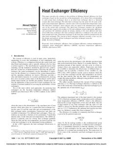
focused on issues related to use of secondary refrigerant for supermarket refrigeration at low temperatures (evaporating temperatures as low as -35°C). Experimental program is focused on display case performance. A system simulation has also been developed. The same state of the art, single deck, low temperature display case, supplied by one of the sponsors, is first tested in baseline mode with R404A evaporating in the evaporator. The same evaporator is later converted into a heat exchanger by removing the T.XV, distributor and suction line heat exchanger. Defrost in the baseline mode used a 3kW electric heaters while in tests with secondary loop defrost was done with the warm coolant. Experimental results demonstrated that the same display case operated better when refrigerated by secondary fluid (potassium formate and potassium acetate so far) than with R404A. More details about the performance and the test procedure could be found in Hmjak (1997a), (1997b), Terrell, Mao, Hmjak (1997) and Mao, Terrell, Hrnjak (1998). Additional elements needed for analysis in this paper are given in the following paragraph . The focus ofthis paper is on one of the reasons for better performance: difference in frosting and defrosting of the same coil when used as an evaporator for R404A and heat exchanger for potassium formate. COM?AR ISON OF THE DISPLAY CASE PERFOR MANCE WHEN OPERAT ING WITH DIFFERE NT REFRIGE RANTS Tests are conducted according to the procedure described in ANSI/ASHRAE Standard 72 - 1983 "Method of testing open refrigerators for food stores" at the Laboratory for Commercial Refrigeration, ACRC, University of Illinois. The display case under the test is placed in environmental chamber and exposed to conditions described in the Standard. The display case is filled with test packages and dummy packages. After repeatable conditions occur, the recorded data for a 24-hour period is treated as one test level (defined by Standard). Repeatability of test conditions is determined. by ± 0.2 oc difference in package temperatures at the beginning and end of the 24 hour period. Package temperatures generally take longer to reach steady state compared to other parameters (air and refrigerant temperatures). Adequate refrigeran t flow in baseline tests to have minimum superlteat for stable operation is supplied as demanded by the case. This is achieved by changing the suction pressure and proper adjustment of the thermoexpansion valve to obtain maximum flow rate and maintain stable superheat signal. More details could be found in Hmjak, Terrell and Mao (1996, 1997). The schematic of the display case is shown in Figure 1. It shows the location of the test packages (with thermocouples) and dununy packages along with thermocouples in the air ducts of the display case. The positions of the thermocouples on the heat exchanger are shown in Figure 2. Note that heat exchanger shown is with headers (for secondary refrigerant) but it is the same unit used in baseline tests. The only
277
RetumA ir
difference is that the header replaces distributor and that the suction line heat exchanger used with R404A is eliminated in tests with secondary fluids. Approach described here is to use existing state of the art display cases, run the with tests baseline in as oil and rant refrige on, operati conventional Fig. 1. Position ofthe test packag es in the display case.
and then compare it to operation when served with single phase secondary refrigerant. Two steps in testing display case with secondary refrigerant are taken: 1. Same heat exchanger as evaporator substituting distributor with the inlet header and 2. Modified heat exchanger that is more suited to single phase secondary refrigerant (fin and tube Figure 2. Heat exchanger and positio ns ofthenn ocoupl es
spacing, circuiting, etc.). Data shown here are the part of the 0 first step. Heat exchanger · surface when operating with secondary E -s refrigerant is reduced by removing ~• -10 suction line heat exchanger used in t baseline tests . J-15 One key issue is the choice of ~ ... -20 comparison criteria. Our approach is to compare performance based on -25 produc t temperature because the &' PhOsslo.lll Formate velocity ...0.33mts. 280