(recovered via the liquid collection and vapour recovery systems) to reactor grade and are referred .... and meaningful error messages keep the user on track. The user ... a dialog, so that input data can be entered or edited (Figure 3). Clicking ...
CA9900051
HEAVY WATER UPGRADER DYNAMIC SIMULATION (UGDYNSIM) KM. Kalyanam, S.K Sood and F. Fusca Ontario Hydro 700 University Avenue, Toronto, Ontario M5G 1X6 A. Busigin NITEK Corporation 38 Longview CRT., London, Ontario N6K 4J1 1.0
INTRODUCTION
Water distillation columns, operating under vacuum, are widely used to separate light water from heavy water. In CANDU nuclear stations, they are used to upgrade low purity heavy water (recovered via the liquid collection and vapour recovery systems) to reactor grade and are referred to as Heavy Water Upgraders. Reactor grade heavy water is recycled to the appropriate reactor systems and the D2O depleted light water is rejected via the active liquid waste discharge system. Since the isotopic concentration of the recovered heavy water changes frequently, the concentration of D2O in the feed to the upgraders is not constant and the upgraders are never operated under steady state conditions. The existing upgrader process simulation model, UGSIM[11, is a steady state model that uses binary approximation to simulate HMD separation. The UGSIM code, therefore, is only capable of giving the end point of the operating trajectory from the previous feed composition to the new feed composition. Thus, for an upgrader under normal operation, this provides only a rough approximation of the reality. Ontario Hydro has now developed an upgrader dynamic simulation code (UGDYNSIM), with a point and click Microsoft WINDOWS 95 or WINDOWS NT user interface, that will predict the time dependent performance of the upgraders. The UGDYNSIM is a rigorous distillation model that accounts for the oxide forms of H, D and T (i.e., all the six water species). A fast 32-bit program has been used to simulate systems of any size, with multiple interlinked columns. The user specifies the number of theoretical stages, column pressure profile, reboiler duty, system inventory, feed composition etc. The simulation can be continuous or in specified time-steps. The UGDYNSIM program is the most sophisticated heavy water distillation simulation program in existence today. This paper presents the features and capabilities of UGDYNSIM 2.0
SPECIAL FEATURES OF WATER DISTILLATION
As compared to the simulation of distillation columns in the petrochemical industry, water distillation column simulation presents special difficulties. • Water distillation is an isotope separation process characterized by very slight differences in relative volatility between the species being separated. • The degree of separation in a typical water distillation column used for heavy water upgrading or production is very high.
• • •
The relative abundance of H 2 0 to D2O as measured by the H.D ratio can change by six or more orders of magnitude from the top of the column to the bottom of the column. The number of theoretical plates in a water distillation column is usually 400 or more. By comparison, a large distillation column in the petrochemical industry has 40-50 plates. Water distillation involves the additional complication of the following rapid equilibration reactions in the liquid phase: H2O + D2O o 2HD0 H2O + T2O o 2HT0 D2O + T2O o 2DT0 The equilibrium constant for these reactions is approximately 4, which is the ideal value based on a statistical rearrangement of the H, D and T atoms. Since in most applications, the T2O concentration is extremely low, tritium (T) is primarily found in the HTO and DTO species. Because of the equilibration reactions, water distillation is reactive distillation.
Due to these special features, water distillation cannot be properly simulated by a simulation code developed for the petrochemical industry. There are only a few proprietary water distillation codes in existence, with the most rigorous and sophisticated ones developed by Ontario Hydro. 3.0
DISTILLATION COLUMN THEORY
The component mass balance equations for a water distillation column with fixed inventory (mole) per theoretical stage are expressed by the well known tridiagonal matrix equations: li.n if
~ Ji.n
a
i,nXi.n-\
^i,nXi,n
C
i.n i.nXXi.n+\ i
for i = 1..., m and n = 1..., TV, where m is the number of components, TV is the number of theoretical plates or stages, qin is the stage inventory (mole) of component i for stage n, xin is mole fraction, fin is feed rate (mole/s), and the coefficients ain, bin, cin are defined as: a
Un = 4 - 1
*,., =-Ln -DLn ~KUn(Vn C
i,n
=
K-i.n+V
+Dvn)
u+1
where Ln = liquid flow leaving stage n (mole/s), Vn = vapor flow leaving stage n (mole/s), Dvn = vapor product flow leaving stage n (mole/s), D^ = liquid product flow leaving stage n (mole/s), K-i«= vapor-liquid equilibrium ratio for component i on stage n (dimensionless),
The differential equations described above must be integrated numerically. For absolute stability, an implicit Euler method is used in UGDYNSIM. The accuracy of the numerical integration improves for small time steps. However, smaller time steps require more computation time to simulate a given simulation scenario. The step size can be experimented with to determine the appropriate size. If reducing the step size by a factor of two makes an insignificant difference to the simulation results, then the step-size is small enough for practical purposes. 4.0
LIQUID-VAPOR EQUILIBRIUM RELATIONS
For water distillation, the vapor liquid equilibrium ratio calculation assumes an ideal solution of water species. Therefore, K
-
P '
where p*n is the vapor pressure of pure component i at the temperature of stage n and Pn is the absolute pressure of the stage. For water distillation, the assumption of ideal solutions is generally accepted as being very accurate. The vapor pressure calculations in UGDYNSIM are based on the procedure described in the paper by W. Alexander Van Hook. (2] 5.0
BENEFITS OF DYNAMIC PROCESS SIMULATION
Dynamic simulation of a complex process system is valuable because it provides insight into system operation that is difficult to obtain even with field experience. For example, in unsteady state operation of a heavy water upgrader, the head product and bottom product variations with time are a complex function of feed composition, control actions, and many other process variables, including past history. The complexity is such that hand calculations are of limited value, and "intuition" based on experience is only a very crude guide as to what operating performance can be expected. The benefits of the dynamic process simulation code are as follows: •
Realistic process model (Current UGSIM Steady State Model is only a very rough approximation of reality);
•
Allows simulation of automatic control to evaluate its potential benefits and assess control strategies;
•
Accurately predicts time required to achieve desired column profile under total reflux and normal operation modes;
•
Allows evaluation of different operating scenarios and optimization of operational strategy;
•
Increased plant efficiency due to a better understanding of the process system operation;
•
Provides improved troubleshooting and diagnostic capability;
•
Useful as a training tool (The user friendly program interface promotes faster learning by new users, greater use by existing users, and continuity through staff turnover);
•
Integration of program with on-line process control system;
•
Permits performance monitoring of upgrader packing under dynamic operating conditions. Within the heavy water upgrader distillation columns, saturated vapor flows up and is contacted with liquid which flows down the column by gravity. The columns are packed with copper/bronze packing material which provides a large surface area for contacting downward flowing liquid with upward flowing vapor. The separative power of a column is characterized by its number of theoretical plates (NTP). The terms "theoretical stages", theoretical trays" and "theoretical plates" are often used interchangeably. The packing efficiency is characterized by the Height Equivalent to a Theoretical Plate (HETP), which is the height of packing required to provide the amount of separation equivalent to a theoretical plate. Usually under steady state operating conditions (i.e., the column pressure, reboiler boil-up rate, feed concentration, feed rate and product draw-off rates are maintained constant for at least two or three days), the top and bottom products concentrations are determined by sampling and analysis. With the use of steady state simulation codes (such as UGSIM), the actual number of theoretical plates (NTP) are determined. From the total packing height in the columns and the estimated NTPs, the HETP is calculated. Due to the large water inventory in the columns (several megagrams), it normally takes about 7 to 10 days of operation to achieve near steady state. Stations seldom have the large inventory of the required feed stock of the same feed concentration to carry-out such a lengthy packing performance assessment. Periodic packing performance monitoring is becoming increasingly important, since the corrosion of the packing material (due to impurities in the feed water) has the effect of slowly deteriorating the packing efficiency. With the use of the dynamic simulation code, the performance monitoring can be carried-out under total reflux or normal operation, without the lengthy wait to achieve steady-state. The only requirements are constant pressure and boil-up rate.
6.0
FEATURES AND CAPABILITIES OF THE UGDYNSIM
6.1
Development of UGDYNSIM Code
The UGDYNSIM dynamic simulation code is designed to run on PC computers under the 32-bit Windows 95, Windows NT or compatible operating systems. The program allows the user to setup and run upgrader operation simulation scenarios in a flexible manner with a point and click Windows 95 or Windows NT user interface. The UGDYNSIM simulation program is descended from the FLOSHEET code P1, UGSIM code m , DYNSIM code[4], and Single Column Generic UGDYNSIM [5] code. The FLOSHEET and UGSIM codes are steady state codes developed by Ontario Hydro starting in 1984, and both these codes
are still widely used today. The fully dynamic DYNSIM and Single Column Generic UGDYNSIM were developed for Ontario Hydro by NITEK Corporation after 1990. The dynamic distillation column algorithms in UGDYNSIM are very similar to those in CFSTIM t6] developed by the Canadian Fusion Fuels Technology Project (CFFTP), a dynamic simulation code used internationally for the International Thermonuclear Experimental Reactor (ITER) project. 6.2
UGDYNSIM Program Features
UGDYNSIM is a realistic upgrader process model that accurately determines the time required to achieve desired column profile under total reflux and normal operation modes. It allows study of control strategies and simulation of automatic control to evaluate its potential benefits. Different operating scenarios can be evaluated to optimize the operational strategy. It is an extremely useful tool for upgrader operator training. It provides flexibility for future integration of simulation program with on-line process control system. 6.2.1 Main Window. When the program is started, the Upgrader page is displayed in the main window. A typical main window for a moderator upgrader is shown in Figure 1. The main window is configured to mimic the station upgrader system, including all the major equipment and feed valve locations. Fie
Simulation Setup
Charts Help
4 Ontario Hydro Btuce Nuclear Gene/ethg Station *8' Heavy WateiUpgudei Dynamic Smiaticn Piogrem Tim»Ih):133.SS7.0.000 2B MMsrator H e M Product D2O %
Profie Data Summary POJ.020 X
end
0.184-
Elapsed Time (h) Moderator Bottom Product 0 3 3 %.
Elapsed Ttaw (h) Heat TtoKsort Head Product D2O %
0.1947 0.2061 0.5863 1.5059 3.6362 8.2467 17.1U< 31.0566 47.4502 61.2909 70.0805 74.6655 84.1021 90.5771 94.6571 97.0438 98.3838 99.1208 99.5226 99.7412 99.8602 99.S252 99.9609 99.9806 99.9915
T2Q
O/L
0.00240 0.005? 0.009)6 0.03121 0.09668 0.28061 O.TAlOi
1.70808 3.29716 5.37127 7.74147 10.39551 11.42591 12.15830 12.65637 12.99781 13.26211 13.51530 13.8U7S 14.24977 14.91M1 15.97302 17.71264 20.39S60 35.38154
BNGS 'B' Moderator Upgrader
[posjon tt lefere to section top)
Heat Tronstxrt BcRom Product D2O %
P!DS:lpoint.S9.92XD?O 337SUh 99.9915% D2O 25.3815 Cut.
.steam 'condensate Run
|
Step
84.4902% D2O 11.1690 CM.
Step
flfNTSLANMenu-INTSSl..
Figure 1: UGDYNSIM Main Window Showing Bruce NGS 'Bf Moderator Upgrader Mimic Panel.
The simulation may be setup, started, stopped and restarted at any time, with control system adjustments made via mimic screen, just like with a real control console. Extensive error checking and meaningful error messages keep the user on track. The user is notified about missing or erroneous data and prompted for the correct inputs. Four charts are preconfigured along the left side of the screen: •
moderator upgrader head product D2O %
•
moderator upgrader bottom product D2O %
•
heat transport upgrader head product D2O %
•
head transport upgrader bottom product D2O %
At the bottom left hand comer of the screen are three buttons Run, Step and Stop, which are used for starting, stepping and stopping a simulation run. Clicking on Run starts a simulation to run continuously until the Stop button is pressed. Clicking on Step causes the simulation to proceed only one integration time step. The Zero button just above the four charts zeroes the time simulation time. The File, Simulation, Setup, Charts and Help menus are used to load/save simulation cases, control the simulation run, setup the simulation, view charts, and get program help. These menus are described in more detail later. Clicking on the Heat Transport Upgrader page tab changes the page to the Heat Transport Upgrader mimic panel, which is similar to the Moderator Upgrader mimic panel. A typical main window for a heat transport upgrader is shown in Figure 2. Generally, clicking on an equipment tag will bring up a dialog to configure the equipment. For example, clicking on the feed evaporator EV-2 tag on the moderator upgrader mimic will bring up a dialog, so that input data can be entered or edited (Figure 3). Clicking on the V1172 tag on the moderator upgrader mimic will bring up a valve open/close dialog to confirm the status of the valve. Closed valves are colored amber, while open valves are colored white. Generally, two connected feed valves cannot be open simultaneously. When valves are opened and closed, simple consistency check logic ensures physically reasonable operation.
fife
Simulation Setup Charts Help
4fei Ontario Hydro
"•*"""»•* E
Bruce Nuclear Generating Station "B" HeovyWaterUpsrader Dynamic Simujecion Program Timelhfc 0.000.0.000 Zeiol
Profie Data Summary P o t 020 X T20 CrTka
Moderator Head Producl O2O %
Bapsed Urns (hj Moderator Bottom Product D2O %
Etopud Thw Ch> Heot Transport Mead Product D2O
Hsat Transport Bottom Producl D2O
32
0.1020 0.04367 0.04367 0.1020 0.04367 0.1020 0.04367 0.1020 0.84367 0.1020 0.0436! .0.1020 0.04367 0.1020 26 0.04367 0.1020 25 0.04367 0.1020 24 0.0436T 0.1020 ZS 0.05995 0.2140 22 0.4030 21 0.6730 20 0.13486 1.0K0 IS 0.19723 IS .27104 1.3630 17 0.34923 1.7180 16 0.42581 2.0480 IS 0.50028 2.3710 14 0.58377 2.7510 13 0.71423 3.3580 12 0.97746 4.4520 11 0.9867D 4.4470 10 0. 4.3580 9 0.95810 4.1960 8 0.92202 4.0140 7 0.88121 3.9450 0.8S437 6 (.3260 0.88506 S 6.0690 1.08218 4 11.4590 1.67S30 3 24.9090 2.91137 Z 49.8230 4.576S4 1 79.0129 6.04999 ret, 98.3388 (pontion # refers to section top} Food 35.23: D20 30.2 Ci/1.
BNCS 'B 1 Heat Transport Upgrader
20.00 u h 0.1000% D2O O.O5S0CUL
n o Seuoint • 33.603:020
condensate 1875 Uh O2S3KW)
Run
|
Step
|
Stop
B N T 5 U N M e r « . - | H T S S L . . | jgSnaojt • Sh»e«jeEvalC...
3KMtaosoHWocd-Documoni3| •
Figure 2: UGDYNSIM Main Window Showing Bruce NGS 'B' Heat Transport Upgrader Mimic Panel.
Ontario Hydro
Modetatot Upgjadci j Heot Tiantooft Upgtada
8iu=o Nuclear Gsneiattig Station B' HoavyWdoUpgiadei Dynmic Sinxiation Program Profie Data Summary lima th* 0.000. aODO Zoo I Po».D20 a: T z o an. end 0.1000 0.05SOO M3dere&or Head ProoXtct O2O % 0.1020 0.04367 0.0599S 0.2140 0.08868 0.4030 0.13488 0.6730 0.19723 1.0040 Q.Z7104 1.3630 0.34925 1.7180 0.42581 2.0460 O.S0028 2.3710 0.S8377 2.7S40 Moderator Bottom Product D2O V 0.71423 3.3SS0 0.97746 4.4S20 0.98670 4.4470 4.3S80 4.1960 0.95310 4.0140 0.92202 3.9450 0.8SL21 4.3260 0.85437 6.0690 0.88506 Heat Transport Head Producl D?O % 11.4 1.08218 24.9090 1.67S30 49.8230 2.91137 79.0129 4.S7654 red 93.3388 6.04999 [position Q refers to section top]
BNGS "B\ Moderator Upgrader
Heat Transport Bottom Product D2O
j
Slop
j
Stop
NTS LAN Menu• [NTS 51... | jgSnacit • Shareware E»d C . . . | | g P20 Upgtadar Snraila...
^M«aoso(IWoid-Docunenl3|
Figure 3: UGDYNSJM EV2 Dialog Shown When Clicking EV2 Tag
6.2.2 SetUp Menu. Selecting the SETUP menu (shown in the top left-hand side of Figure 1) brings up the upgrader setup dialog shown in Figure 4. The setup dialog allows user input of upgrader configuration data. The user specifies the reboiler and condenser data such as pressure, temperature, flowrates and inventory. For each packed section of the upgrader, the user specifies the number of stages, top and bottom pressures, top and bottom D2O and T2O concentrations, water inventory in the packing, and water inventory in the tower sumps and the distributors (sump inventory). The top and bottom pressures, and D2O and T2O concentrations for each section can be set based on station operating data and sampling and analysis. If such information is not available, these values can be based on linear extrapolation of the overall tower top and bottom values. This capability to specify the parameters of each section is a very useful feature of UGDYNSIM, since this allows the user to simulate the effect of loss of efficiency in some sections on the upgrader performance. For example, if the liquid distributors in some sections are partially or completely plugged, the liquid maldistribution will result in loss of separation efficiency. Several simulations can be run using different number of stages in these sections. By comparing the simulation results with the actual operating data, the number of stages in the plugged sections can be predicted. Using the predicted number of stages, simulations can then be carried-out to optimize the operation strategy, until future maintenance shutdown.
Efe
S'mJafcn Setup Chats Heb
Bruce Nuclear Ge Heavy WataUpg Dynamic Sirmiatio
Bruce NGS '6' Moderator Upgrader Packing Section Data Inventory
Top 02O
(U
m
sec nts
TmH 0.000.0. ModeralorHe»
Baps
Heat Transport Hi
1 2 3 4 5 6 7 8 S 10 11 12 13 14 15 16 17 18 19 20
20 20 20 20 20 20 20 20 20 20 20 20 20 20 20 20 20 20 20
194.000 194.000 194.000 194.000 194.000 194.000 194.000 194.000 194.000 194.000 194.000 194.000 194.000 194.000 194.000 194.000 1S4.000 194.000 194.000 194.000
20
Top T20 (Ci/L)
Bot.
7.9013E+01 4.1605E+O0 9.8339E+01 4.9823E+01 2.6467E-HJ0 7.7689E+01 2.4909E+01 1.5230E+00 4.8357E+01 1.1459E+01 9.83S0E-01 2.3967E+01 6.O690E+CO 8.O460E-O1 1.1043E+01 4.3260E+00 7.7670E-O1 5.9220E+00 3.9450E+00 8.0110E-01 4.2860E+00 4.0140E+00 8.3820E-01 3.9420E+00 4.1960E+00 8.7100E-01 4.0220E+00 4.3580E+00 B.9150E-01 4.2050E+00 4.4470E+00 8.9700E-01 4.3640E+00 4.4520E+C0 3.8860E-01 4.4490E+00 3.3580E+00 6.4930E-01 4.4500E+OO 2.7540E+00 5.3070E-01 3.3190E+00 2.3710E+00 4.5480E-01 2.7310E+00 2.0480E+00 3.8710E-01 2.3540E+00 1.7180E+00 3.1750E-01 2.0320E+00 1.3630E+00 2.4640E-01 1.7000E+00 1.0040E+00 1.7930E-01 1.3450E+00 6.7300E-01 1.2260E-01 9.8600E-O1
RefaievcCorrpoaitionDataFiomSitmJation |
Bot. T20 (Ci/L)
020
(JO
S.4353E+O0 4.0850E+O0 2.5769E+O0 1.4832E+O0 9.6360E-01 8.0O80E-O1 7.7710E-01 8.02B0E-O1 B.4000E-01 8.7240E-01 8.9210E-01 8.9680E-01 8.8790E-01 6.4130E-01 5.2640E-01 4.5130E-01 3.8370E-01 3.1390E-01 2.4290E-01 1.7620E-01
Condenser Specification
Steam Pressure (kPat (SOO™
CoofingWat«T©mc»tati«(Ct [5.00
RebcfciinvenloyfUt |S2000
Condenser Invertotyp-i 120.000
HebofcrDSOK): |S8.3330 "
Condenser D20 (2* (OTOM
Rcboil«T201Ci/U: I |i Accept
Run
|
Slap
|
Slop
Condenset T20 [CiA.J [0.0500 |
(kPa) 21.42 20.83 20.25 19.67 19.08 18.50 17.92 17.33 16.75 16.17
15.58 15.00 14.36 13.73 13.09 12.45 11.82 11.18 10.55 9.91
Bot. P (kPa) 22.00 21.42 20.83 20.25 19.67 19.03 18.50 17.92 17.33 16.75 16.17 15.58 15.00 14.36 13.73 13.09 12.45 11.82 11.18 10.55
Snip Inv.
56-
/
52-
y^
48 /
•—*»M. 40' 36 32
/ / . _
_
—
-
—
—
—
•
•
24 20' 1fi'
^ 100
200 PHnt.. |
u| Ifcs
400
500 600 Elapsed Time pi)
700
800
900
l
S LON Menu-[NTS S I . |
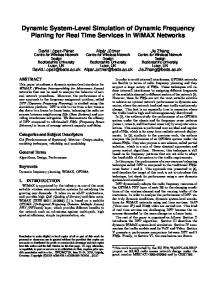
Figure 10: Trends of Head Product, Bottom Product and Feed Flowrates
1.000
Additional information obtained from this simulation are: •
The final upgrader feedrate is about 66 kg/h.
•
Upgrader tower D2O isotopic profiles to determine the correct feed valve location. For the above example, the optimum feed valve is V1260 (located above the packing section # 13).
The user can also extract other output data from UGDYNSIM as discussed in Section 6.0. 8.0
FUTURE PLANS
Customized versions of UGDYNSJJvl have been developed for some of the Ontario Hydro heavy water upgraders (at Bruce NGS B and Pickering NGS). It is anticipated that by 1998 all Ontario Hydro heavy water upgraders will have customized versions of UGDYNSIM. Extensive testing and calibration of the code using station operating data will be carried out in the near future.
9.0 REFERENCES 1. BUSIGIN, A., "Users' Manual for the UGSDVI Water Distillation Simulation Program", Ontario Hydro, Design & Development Division Report #89280, June 1989. 2. ALEXANDER VAN HOOK, W., "Vapor Pressures of the Isotopic Waters and Ices", The Journal of Physical Chemistry, Vol. 15, p 1234-1244, 1967. 3. BUSIGIN, A. and SOOD, S.K., "FLOSHEET - A Computer Program for Simulating Hydrogen Isotope Separation Systems", Fusion Technology, 14, 529 (1988). 4. BUSIGIN, A. and SOOD, S.K, "Steady State and Dynamic Simulation of the ITER Hydrogen Isotope Separation System", Fusion Technology, 28, 544 (1995). 5. BUSIGIN, A., "UGDYNSIM Heavy water Upgrader Dynamic Simulation Program Preliminary Users' manual", DRAFT, January 15, 1996. 6. BUSIGIN, A. and GIERSZEWSKI, P.J., "CFTSIM-ITER Dynamic Fuel Cycle Model", paper presented at the Fourth International Symposium on Fusion Nuclear Technology, Japan, 1997.


![Water density Water density Dynamic viscosity Dynamic viscosity [kg m ]](https://m.moam.info/img/260x300/water-density-water-density-dynamic-viscosity-dyna_5c96594d097c47ad2b8b4622.jpg)