Oct 25, 2006 - cores to speed up the JPEG compression algorithm. We show two ... (in this case a JPEG application) and try to parallelize it with a num-.
Heterogeneous Multiprocessor Implementations for JPEG : A Case Study Seng Lin Shee†‡ , Andrea Erdos† , Sri Parameswaran†‡ †
School of Computer Science and Engineering, The University of New South Wales, Sydney, Australia ‡ National Information and Communications Technology Australia (NICTA), Sydney, Australia∗ {senglin,
aerd537, sridevan}@cse.unsw.edu.au
Abstract
that the speedup increases at a faster rate than at which the area increases (i.e. have more performance per gate than in a single processor). To perform this parallelization, we take a single application (in this case a JPEG application) and try to parallelize it with a number of processors. We try two separate methods, one a master-slave model and the other a pipeline model. We start with identical processors (i.e. the most powerful standard processor available within the suite of tools we use), and then either enhance it with additional instructions (if a particular processor is the bottleneck), or if the workload is little, diminish it by the use of a lesser processor with reduced cache. The paper is organized as follows: Section 2 gives a broad overview of the multiprocessor research thus far and Section 3 specifies the benchmark application and platform which this case study is based on. Section 4 specifies the different configurations and methodologies used to partition and organize the multiprocessor configurations, and Section 5 reports the experimental methodology used in this case study. Section 6 analyzes the performance improvements for each system and presents a walk through on selective optimization on a particular configuration. Finally, in Section 7 the conclusions are summarized.
Heteregenous multiprocessor SoCs are becoming a reality, largely due to the abundance of transistors, intellectual property cores and powerful design tools. In this project, we explore the use of multiple cores to speed up the JPEG compression algorithm. We show two methods to parallelize this algorithm: one, a master-slave model; and two, a pipeline model. The systems were implemented using Tensilica’s Xtensa LX processors with queues. We show that even with this relatively simple application, parallelization can be carried out with up to nine processors with utilization of between 50% to 80%. We obtained speed ups of up to 4.6X with a seven core system with an area increase of 3.1X.
Categories and Subject Descriptors C.4 [Performance of Systems]: Design studies; C.1.3 [Other Architecture Styles]: Heterogeneous (hybrid) systems
General Terms Design, Experimentation, Performance
1. Introduction As multi-billion transistor system-on-chip era approaches, designers constantly ponder upon effective methods of utilizing these resources. Tighter time to market deadlines, reduced availability of workforce per transistor, increased possibility of design errors, and phenomenal mask costs have all contributed towards making design somewhat modular, with well tested components. One method to simplify the design process, is to use processor cores as main components. Recent advances in processors as intellectual property cores, customization options within such processors (such as cache sizes, additional instructions etc), and superior design tools have all enabled numerous such processors to be used within a single SoC. In a typical multi-processor SoC, designers often partition an application into separate tasks at a fairly high level of granularity, and implement each task in a separate processor. For example, in a game console, the audio would be implemented in one processor while the video might be implemented in another, and the physics in yet another and so on. Such processing is comparatively easy to achieve and allows a fair amount of parallelism, reducing the workload of the operating system. In this paper we try to explore the possibility of further parallelization at a lower granularity than at the level explored in the previous paragraph. We want to further explore the possibility of speeding up the application with heterogeneous components such
2. Related Work Multicore architectures are becoming prevalent in SoC designs. For example, the design in [16], is common in DSP systems where multiple processing entities perform computation on different parts of the system concurrently. A general purpose multiprocessor system (single ISA) enables programmability and speeds up design-to-market time. Multi-ISA multi-core architectures have been proposed in [17], which requires different processors in the system to execute different instruction sets. Such cores typically address vector/data-level parallelism and instruction-level parallelism simultaneously. However, a single-ISA heterogenenous [8] system provides the advantage of easily mapping any application stage to any of the cores in the multi-core system. Various heterogeneous multiprocessor systems have been implemented, primarily in the automotive real-time systems [4] and video / image encoding domain. The authors in [18] explored the use of a heterogeneous system in a real-time video and graphics streams management system, while in [22], the authors applied an adaptive job assignment scheme to perform data partitioning for a multiprocessor implementation of MPEG2 video encoding. A heterogeneous multiprocessor (five cores) for HDTV systems was developed in [7]. Gopalakrishnan et. al [10] used heterogeneous systems in a different manner. The work generalizes the approach started by Baruah [6] which replicates recurring tasks on multiple processing units to ensure a degree of fault tolerance. Maintaining replicas of a task at different processors ensures that single processor failures will be tolerated well. A multicore system would have various communication schemes to provide the neccesary link between each core in the system. Kim et. al. [14] developed a new CDMA-based on-chip interconnection network using a Star NoC topology. To enable quick design of a
∗
National ICT Australia is funded through the Australian Government’s Backing Australia’s Ability initiative, in part through the Australian Research Council.
Permission to make digital or hard copies of all or part of this work for personal or classroom use is granted without fee provided that copies are not made or distributed for profit or commercial advantage and that copies bear this notice and the full citation on the first page. To copy otherwise, to republish, to post on servers or to redistribute to lists, requires prior specific permission and/or a fee. CODES+ISSS’06, October 22–25, 2006, Seoul, Korea. Copyright 2006 ACM 1-59593-370-0/06/0010 ...$5.00.
217
multi-core processor system and the evaluation of its interconnect system, Wieferink et. al [21] developed a methodology for retargetable MP-SoC integration at the system level based on LISA [20] processor models and the SystemC [1] framework. Single core application utilizes instruction level parallelism which is enabled by pipeline processors. Multiprocessors are able to exploit task level parallelism by executing different task on separate cores simultaneously. Different schemes have been developed, such as the reuse of the pipeline [9] scheme. Several pipelining methods have been explored. Jeon et. al [13] partitioned loops into several pipeline stages. The iterative algorithm proposed increased parallelism and reduced the hardware cost of the designed system. Kodaka et. al. [15] combined the both course grain and fine grain parallelism (which includes loop pipelining) using a single OSCAR chip multiprocessor. The work exploits course grain task, loop parallelism and instruction level parallelism using the OSCAR compiler. The OSCAR chip comprises of several processor-element (PE) connected to local memory and shared memory, facilitating data transfer among processors. Banarjee et. al. [5] incorporated heterogeneous digital signal processors with macro pipelining based scheduling. The technique utilized a signal flow graph (SFG) as a basis for partitioning. The work shows that heterogeneous multi-cores are able to improve the throughput rate several times that of the conventional homogeneous multiprocessor scheduling algorithms. Our work differs from all of the above by the informal exploration of the design space of two differing multi-processor core architectures: one, a master-slave model and another a pipelined model. The exploration of the pipeline model not only explores differing cores, but also enhances the core with instructions and diminishes them by reducing cache sizes, until the pipeline stages are roughly balanced. By careful design we show that our pipeline system improves performance by approximately five times while consuming three times the area.
1
Read RAW
5
DCT horizontal
9
Initialize QT
2
RGB to YCbCr
6
Quant / Zigzag
10
JFIF Markers
3
Level Shift
7
Huffman
11
Close bitstream
4
DCT vertical
8
Write to file
Figure 1: The main stages in a JPEG encoder.
3.2
Baseline Processor Description
This case study utilizes Tensilica’s Xtensa LX processor [2]. The Xtensa LX is part of the line of Tensilica’s microprocessor core family which is configurable, extensible and supported by automatic hardware and software generation tools. The synthesizable core is configurable to allow designers to precisely tailor each processor implementation to match the target application requirements. The Xtensa core ISA has a 24-bit instruction set base and allows 16-bit instructions for higher code density. All instructions can operate on 32-bit data. The Xtensa LX, like previous Xtensa processors, is able to support extended instructions, which are written in Tensilica Instruction Extension (TIE) language. Such instructions are able to do the work of multiple instructions of a general-purpose processor. Extended instructions include fusion instructions [19], SIMD/vector instructions and FLIX [3] instructions. Flexible Length Instruction Xtensions (FLIX) are VLIW-like instructions whereby multiple operations can be performed in a single instruction. TIE queues and ports have been introduced in Tensilica’s Xtensa LX processors. These features are used to communicate to the world outside of the processor and can communicate at a much wider bandwidth than existing interconnects. Queue interfaces are used to pop an entry from an input queue for incoming data or push data to an outgoing queue. The logic to stall the processor when it wants to read an empty input queue or write to a full output queue is automatically generated by the Xtensa Toolset. Ports are wires that the processor uses to directly sample the value of an external signal or drive the value of any TIE state on external signals. Functions are created to push and pop from the queues. The functions are blocking functions; as a push into a full queue or a pop from an empty queue results in a stall of the particular pipeline stage. These functions are TIE instructions and form part of the extended instructions of the Xtensa LX processor architecture (refer to Figure 2). The configuration of the base processor used in the case study has been optimized to provide satisfactory results when executing the benchmark application under a single processor system and is shown in Table 1 as LX1. Also shown is a highly stripped down version of the Xtensa LX processor LX2 which will be used to replace under-utilized cores to save area and power (see Section 4.2).
3. Background This case study is based on mapping different parts of the benchmark program and employing a set of industrial tools to rapidly optimize and simulate the entire system in a multiple processor configuration. The partitioning of the program (initially based on functions in the source program) is performed by analyzing the benchmark results of the simulation. The set of the industrial design tools enable us to quickly explore the extent of improvements and area usage of a heterogeneous multiprocessor system.
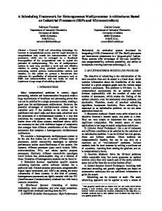
3.1 Case Study Application A freeware JPEG compression algorithm implementation is used in this case study. The simplistic nature of the program benefits this case study as various sections of the code can be distinguished, partitioned and separated into a multiple processor configuration. Figure 1 shows the various partitions or stages of the program which have the possibility to be allocated to different processors. The arrows indicate the flow of RAW bitstreams through the various stages of the encoding process before being written out to file. The JPEG encoder program initially accepts a configuration file which specifies the name of the RAW file to read, the quality factor and the format of the RAW image. These tasks are performed in Stage 1. The program then proceeds to initialize the quantization tables and write the appropriate JFIF header information to the output file, which includes Quantization and Huffman tables (stages 9 and 10). The program allocates two main buffers; one for the complete RAW image which is read from file and the other for the resulting JPEG file. The JPEG program then starts reading RGB values from the buffer and converts them to YCbCr values (stage 2). These values are then value shifted (stage 3) (based on JPEG specifications). A macroblock is then selected one at a time in sequence of Y, Cb and Cr to be DCT transformed and quantized with the values ordered in a zigzag manner (stages 4, 5 and 6). The pixel streams are fed into the Huffman encoder (stage 7) which processes these streams serially. The generated code is finally output to a file (stage 8).
Parameter Speed Process Pipeline length Size Core Size Core Power Memory Area (mm2 ) Instruction Cache Data Cache ISA Instruction Options
Max instruction width PIF interface width
LX1
LX2 533 MHz 90nm GT 5
63,843 gates 0.32 mm2 74.35 mW 1.76 mm2 32KB 32KB MUL32, MUL16, density instructions, boolean registers, zero overhead loops, TIE wide stores, 32 bits sign extend, TIE arbitrary bytes 8 bytes 128 bits
39,789 gates 0.18 mm2 41.3 mW 0.15 mm2 1KB 1KB density instructions, boolean registers, zero overhead loops, TIE wide stores,
Table 1: Processor Configuration
218
3 bytes 32 bits
4. Methodology
file (stage 9). Within the JPEG application, the RGB to YCbCr conversion (stage 2) is done in parallel by roughly dividing the RAW image file into (N - 1) parts, where N is the total number of cores in the system. These different parts are then sent to the slave cores, which then complete the RGB to YCbCr conversion. The converted data is then sent back to the main core from the slave cores and written to memory in the order that it was sent out. The main core then begins initializing the quantization tables (stage 9), and writes the JFIF [11] headers to the output file (stage 10). When the main core has reached the encoding stage, it organizes the division of data to be encoded by sending out the first macroblock of 64 Y’s, 64 Cb’s and 64 Cr’s to the first slave, the second macroblock to the second slave, and so on. Once each slave has received its macroblock of data, it begins encoding it by performing the LevelShift, DCT and Quantization/Zigzag (stages 3 to 6) functions on the data sequentially, then sends back the encoded data to the main core. Once the main core has sent data to core (N - 1) in the sequence, it then receives the encoded data from each slave core in the same order that it was sent out. The main core then performs Huffman encoding (stage 7) on the received data. The cycle continues, until all macroblocks are processed. If the number of macroblocks is not a multiple of (N - 1), the final macroblocks are divided up unevenly between the number of slave cores. Each system detailed below follows the basic three-core model, with extra slave cores only allowing the data to be divided up further. Each slave core performs the same functions on the data that it is given.
We explore the various ways a multiprocessor system can be configured to speed up a simple application. In this section, we outline the multiprocessor architecture as we increase the number of cores in the system. We show two methods to exploit the parallelism within the code structure of the program. Our methodology utilizes the queue interfaces which are available on Tensilica’s Xtensa LX [2] processors. A simplified JPEG encoder is modified and partitioned to execute on such a system.
4.1 Method I A master-slave model of a multi-core system was implemented with a differing number (from three to seven) of Xtensa LX processor cores, which were instantiated using the Xtensa LX XTMP/ISS environment. In each model, there was only one main core, with (N - 1) slave cores, where N is the total number of cores in the system. XTMP was used to link the main core with the slave cores using TIE queue interfaces, with two interfaces per core, a TIE queue in and a TIE queue out. These TIE queues were implemented using a custom-designed TIE file for each core in the system. TIE instructions were written to retrieve the data from memory on one core and send it via a queue to the receiving core, which then stored the data into memory by means of another TIE instruction . This reduces the overhead of having to store the data in registers before sending it. The MemDataIn and MemDataOut TIE instructions were used to implement this feature, where x is the size of the data in bits. queue FIFO OUT1 32 out /* this is an output queue from main to slave1 */ queue FIFO IN2 32 in /* this is an input queue from main to slave1 */
Three Cores Cores
/* writing to slave1 from main straight from memory */ operation WriteFifoMemMain1 {in AR *addr} {out FIFO OUT1, out VAddr, in MemDataIn16} { /* addr is the pointer to the data to be sent */ assign VAddr = addr; /* here the data to be sent is of size 16 bits */ assign FIFO OUT1 = MemDataIn16; }
Main Slave1 Slave2 Slave3 Slave4 Slave5 Slave6
/* reading from main to slave1 straight to memory */ operation ReadFifoMemSlave1 {in AR *addr} {in FIFO IN2, out VAddr, out MemDataOut16} { /* addr is the pointer to where the received data is to be stored */ assign VAddr = addr; assign MemDataOut16 = FIFO IN2; }
3 cores 1, 7-11 2-6, 9 2-6, 9 -
4 cores 1, 7-11 2-6, 9 2-6, 9 2-6, 9 -
Stages 5 cores 1, 7-11 2-6, 9 2-6, 9 2-6, 9 2-6, 9 -
6 cores 1, 7-11 2-6, 9 2-6, 9 2-6, 9 2-6, 9 2-6, 9 -
7 cores 1, 7-11 2-6, 9 2-6, 9 2-6, 9 2-6, 9 2-6, 9 2-6, 9
Table 2: Master / slave processor configuration
Figure 2: Sample TIE code implementing a TIE queue interface between two cores Communication between the cores is achieved via these TIE queues. Only the main core communicates with each slave core. The slave cores are not able to communicate between themselves. In each model, a send/receive protocol is implemented to check if a core is ready to receive data before sending the data. Special send and receive messages are sent from either the main core to a particular slave core, or vice versa, and the initiator of this exchange then stalls while it waits for a reply. When the non-initiator of this exchange is ready to receive the data (after having received the message from the initiator), it sends an acknowledgement to the initiator which then sends the data. A JPEG encoder can be separated into different stages that can be run on individual cores. An independent program is compiled for each core, depending on which functions that particular core implements. The simulator loads these individually compiled programs onto each core. When encoding a JPEG image file, (as referred to by the control flow diagram in Figure 1), the processors in each system implement each stage according to Table 2. The JPEG encoder allows for parallelization since data is processed at a macroblock (i.e. 8x8 pixels) level. This means that several cores can be processing different macroblocks of data at the same time. Only Huffman encoding (stage 7) must be done serially, due to the nature of the Huffman encoding algorithm. Once the input RAW image file is read (stage 1) by the main core, the quality factor of the RAW image file is sent out to all slave cores, which then begin initializing the quantization tables for the
219
For a three-core system, one main (producer) core organizes the distribution of data between the two slave cores, and also completes the input and output file manipulations, as well as the Huffman encoding. Two slave cores communicate with the main core via TIE queues, and only complete that part of the encoding process that can be parallelized. In particular, as shown in Table 2, these functions are the RGB to YCbCr conversion function, the LevelShift function, the DCT function and the Quantization/Zigzag function. Four TIE queue interfaces are used to communicate between the main core and Slave1, and the main core and Slave2. After the RGB to YCbCr conversion, the main core sends the first macroblock of data to Slave1, and the second macroblock to Slave2. The slave cores then process their share of the data before sending the processed data back to the main core. After Huffman encoding the data, the main core then sends the next two macroblocks to the slave cores and the cycle continues.
Four Cores main
slave 1
slave 2
slave 3
Figure 3: A four core master / slave system Similarly to the three core system, one main (producer) core organizes the distribution of data between three cores. This main core
communicates with each slave core via TIE queues as shown in Figure 3. Six such TIE queues are used, with three input and three output queue interfaces on the main core, and one input and one output queue interface on each slave core. Every three macroblocks of the input image file are divided up and sent to the three slave cores in order. This is visualised in Figure 3. Macroblocks 1,4,7,etc are processed by Slave1, macroblocks 2,5,8,etc are processed by Slave3, and macroblocks 3,6,9,etc are processed by Slave4. Note that for higher numbers of cores in the system, the ordered blocks to be processed is (N - 1)k + x for Slave, where N is the total number of cores, k is an integer value, and x is the particular slave core number. The rest proceeds as per the three processor system. As shown in Table 2, each slave core implements the same functions (those which could be parallelized) whereas the main core implements the input and output file operations as well as other initializations, writing markers, and the Huffman encoding.
A
B
RAW
C
D
E JPEG
Figure 4: A five core system being interconnected by queues. Each processor is assigned a stage of the JPEG pipeline. The main program of the encoder sends the required information to the appropriate stages of the pipeline in order to initialize the quantization tables and JFIF [11] headers which are written out to file. As each pipeline stage only has to wait for the data from the previous stage, the partition program is constructed such that one core reads the RAW image while another writes the encoded JPEG into a new file. Each stage processes data at a macroblock level (i.e. 8x8 pixels). We started with a five core multiprocessor configuration (Figure 4), pipelined into five major stages. The quantization table initialization code shares the same core as that which implemnt the quantization stage of the pipeline. This stage receives initial values from the main program (core A) which reads in encoding parameters which defines the quality of the resulting image. Core D has the necessary code to initiate the writing of JFIF markers and closing the JPEG bit stream. The last core (Core E) is initialized by the first core with the name of the output file and writes any receiving bytes from the previous stage (Core D) to file. Table 4 summarizes the allocated stages to the respective cores.
Five, Six and Seven Cores Extending the four core system, five, six and seven cores are now used, where macroblocks are grouped into four, five and six macroblocks respectively and then sent to the designated slave cores. See Table 2 for details of functions processed on each core. Each extra slave core implements the same functions as all other slave cores, but with less data. The only differences are that the RAW image file is divided into more parts to be distributed to more cores during the RGB to YCbCr conversion stage, and each slave core processes fewer macroblocks of data during the LevelShift, DCT and Quantization stages.
Six Cores We next introduce a new core into the system and allocate the LevelShift stage to the new processor (refer to Table 4). The LevelShift stage accepts YCbCr values from the previous stage, level shifts the values and then pushes it out to the queue in macroblocks of 64 Y’s, 64 Cb’s and 64 Cr’s. As will be shown in Section 6, the introduction of this stage into the pipeline does not increase the overall performance of the encoding process.
4.2 Method II We next investigate a different multiprocessor architecture in a pipeline configuration. The system comprises of different processors, each running a portion of a pipeline stage of a program. Each processor has a possibility of being configured optimally, instantiating only those resources which are appropriate for the particular stage of the pipeline. A heterogeneous processor system minimizes the redundancy of resources, as processors with complex computations may be parameterized with more resources. Communication among processors is facilitated using ports and queues which are provided by the Xtensa LX [2] processor architecture. The multiprocessor pipeline architecture design requires programs which can be broken up into computationally independent blocks. This resembles computational blocks in a pipeline processor architecture [12]. Transfer of data from one processor to another is facilitated by a queue. In the case of the JPEG encoder, the pipeline architecture is ideal as the JPEG encoder displays characteristics of a pipeline nature. The encoding process is divided into stages which are independent of each other. The proposed architecture consists of standalone processors which runs a sections of the JPEG encoder program which have been recompiled as an individual programs. These subprograms which reside in these processors accept data via the queues of the Xtensa processor, perform the neccessary computation, and finally push it to the output queue into the next stage of the pipeline. The computed data traverses the pipeline stages until it is finally written out to file by the last processor in the pipeline. It should be noted that while one processor is computing a workload, the rest of the system is still busy processing workloads for other stages. The scalability of a multiprocessor pipeline architecture depends entirely in the suitability of the targeted program data structure and the control flow of the program. A particular configuration is considered efficient when all processors have equal computational workload (i.e. no processors in the pipeline should be waiting for the next stage to complete).
Seven Cores DCT transformations are known to be very computation intensive and there are special circuits which performs just such a function. In our next approach, the two-dimensional DCT function can be split up into two stages; a one-dimensional DCT vertically and a one dimensional DCT horizontally. A seven core processor configuration benefits from such an approach (refer to Table 4).
4.2.1
Multiple pipelines
The rational of having pipeline implementations is to increase throughput during execution. Similar to a pipeline microprocessor, a pipeline implementation of a JPEG encoder would be able to encode images at a faster rate. Combining both approaches of method I (parallel computations of macroblocks) and method II (pipelining), we are able to exploit further parallelism within the JPEG compression algorithm. The pipelining nature of the previous core systems are maintained. However, from stage four onwards (DCT), macroblocks for luminance (Y), chrominance red (Cr) and chrominance blue (Cb) are processed in separate parallel pipelines. This reduces the processing bottleneck in the DCT and quantization/zigzag stages. These parallel pipelines include DCT and Quantization (with zigzag) (QZ) stages. The outputs of these parallel pipelines then converge into a single pipe where Huffman encoding is performed. Huffman encoding depends on serial inputs and thus, cannot process multiple JPEG streams at any one time.
Nine Cores Following the five pipeline stage multiprocessor approach in Method II, we try to increase the throughput of the middle stages of the JPEG compression pipeline by replicating the Quantization stage of the pipeline due to heavy utilization rates in the cores stages of DCT and Quantization (refer to Table 4). Pipeline flow diverges only at stages four and five (refer to Figure 1) into three separate pipeline flows, before being fed into a single processor during the Quantization stage. E, F and G cores are the Quantization stages and process
Five Cores The JPEG encoding process (Figure 1) exhibits sequential routines which can be broken up into stages, thus allowing the possibility of pipelining the encoding process. These stages represents functions within the original program and is extracted and compiled as a single program which is executed in a single core.
220
using the XTMP environment. With XTMP, different multiprocessor configuration could be set up and simulated in a short amount of time. Y pipeline The simulator allows for communication between the cores and peripherals using a cycle-accurate, split-transaction simulation model DCT QZ without using a clock. The ISS was used to generate profiling data for all cores in the system, which were then profiled using TensilHuffman Write to Raw file Cb pipeline + Encoding file ica’s gprof profiler. The profiles can include the cycle counts for all RGB conversion functions executed by the cores. The ISS can also print a summary + of the total cycle count and global stalls of each core. levelshift DCT QZ Each individual core is connected via the queue interface proCr pipeline vided by the Xtensa LX core using the XTMP environment. We create C-code functions and data structures to model the queues Figure 5: A nine core system with three internal pipeline flows within the XTMP environment. The queues are simple FIFO (firstin, first-out) components that mainly operate via the functions push the Y, Cr and Cb macroblocks separately. These cores intialize their and pop called by each of the connected cores in the simulation respective quantization tables (Y, Cr, Cb). This results in a nine core environment. Queues transmitting RAW bit streams between proprocessor system. cessors are modeled to have 64 entries. A full queue or an empty The utilizations of each core in the system is shown in Table 3. queue would effectively stall the section of the pipeline. Cores We created our multicore processor systems by identifying hotspots A B C D E F G H I within the single processor benchmark application. The hotspots Utilization (%) 76 51 51 51 28 28 28 95 99 were mainly functions identified in Section 3.1. We partition and allocate these functions based on the methodology defined in SecTable 3: Utilizations in a nine core multipipeline system tion 4. An XTMP simulation program, specially customized to genSeven Cores erate profiling and other relevant benchmark information is created for each of these multiprocessor systems. These generated systems Table 3 shows that the utilization rates of the Quantization cores include similar configured cores, not including parameterized com(E, F and G) in the nine core system are very low, prompting us to ponents such as the number of outgoing and incoming queues. replace all three cores with just one. This is due to the bottleneck The toolset also includes the XPRES (Xtensa PRocessor Extenin the second last stage of the pipeline (H), whereby the Huffman sion Synthesis) compiler which creates tailored processor descripencoding has already reached its maximum throughput. Note that tions for the Xtensa processors from native C/C++ code. The XPRES Stage I is not considered since it is constantly looping. Outputs Compiler was used to create custom RTLs for each core in the sysfrom the three separate DCT cores are now channeled into a single tem. Using the designer-defined input of C programs to be anacore which will perform quantization and zigzag transformations. lyzed, XPRES extends the base processor with new instructions, With the seven core multiprocessor system, we have methodologoperations and register files using TIE extensions. It does so by auically reduced the area consumption of the system. Based on the tomatically generating a new TIE file which can be included when utilization rates of each core in the pipeline, we were able to serecompiling the source code. XPRES was used to create a distinct lectively optimize the required cores using Tensilica’s XPRES comTIE file for each core in each system, to optimize each individual piler, which automatically generates TIE instructions (SIMD, FLIX, core using only the C files that are used on a particular core. Each vector, fusion). individual core in the multiprocessor system is compiled through When the runtime of the selectively optimized system closely XPRES to explore the extent of improvements that can be obtained matches the fully XPRES compiled version, we replace the cores via extended instructions. which have very low utilization rates with simpler ones. These inArea counts include the base processor, instruction & data caches clude replacing LX1 cores with LX2 cores (refer to Section 3.2) and and the TIE instructions. Each multiprocessor system generated in progessively reducing the instruction and data caches (until they the case study reads a RAW file and saves it as a JPEG format file. reached the same performance of the fully XPRES compiled version, or reached minimal configurations which was 1KB). This method- The file generated is viewable under any standard image viewing application. ology results in a heterogeneous multiprocessor system which provides high performance improvement to area increase ratio. 6. Results & Analysis A B C D E F G H I
Stages (single pipeline) 5 cores 6 cores 7 cores 1, 2, 3 1, 2 1, 2 4, 5 3 3 6, 9 4, 5 4 7, 10, 11 6, 9 5 8 7, 10, 11 6, 9 8 7, 10, 11 8 -
4.5
Stages (multiple pipelines) 7 cores 9 cores 1, 2, 3 1, 2, 3 4, 5 4, 5 4, 5 4, 5 4, 5 4, 5 6, 9 6, 9 7, 10, 11 6, 9 8 6, 9 7, 10, 11 8
4 3.5 3 2.5
original
Area (original) Area (XPRES) Runtime (original) Runtime (XPRES)
XPRES
1.5
We used Tensilica’s Xtensa RA2006.4 Toolset for the Xtensa LX family of processors. The toolset also provides a set of compilation tools to compile C/C++ code, targeted to our specially configured Xtensa LX cores (refer to Section 3.2). The Tensilica Instruction Set Simulator (ISS) and Xtensa Modeling Protocol (XTMP) environment were used to run the multi-core systems. For each system, multiple Xtensa cores were instantiated and XTMP was used to connect them to peripherals and interconnects. The ISS directly models the Xtensa pipeline and operated as a system-simulation component
8
4
1
0
5. Experiment methodology
10
6
2
2
0.5
Table 4: Processor configuration with multiple pipeline flows
12
Runtime (million cycles)
Cores
QZ
Area (million gates)
DCT
1 core 3 core 4 core 5 core 6 core 7 core 5 core 6 core 7 core 7 core 9 core (M/S) (M/S) (M/S) (M/S) (M/S) (P) (P) (P) (MP) (MP)
0
Figure 6: Performance of multiprocessor systems without optimizations Figure 6 shows the runtime improvements and area increase with respect to the original core, LX1 (refer to Section 3.2). The graph shows the three main architectures used in this case study; master/slave architecture (3, 4, 5, 6 & 7 cores), pipeline architecture (5, 6 & 7 cores) and the multipipeline architecture (7 & 9 cores). It can be observed that the area increase to runtime improvement ratios
221
10
90%
9 8
70%
Performance Increase (X)
Processor Utilization
80%
60% 50% 40% 30% 20% 10% 0%
Initial multipipeline
Fully XPRES compiled
Partial XPRES Partial XPRES Partial XPRES Partial XPRES 1 2 3 4
(a) Utilization of the seven pipeline stage systems
10 9
Area Increase
8
7 6 5
7 6
Performance Improvement
5
4
4
3
3
2
2
1
1
0
Initial m ultipipeline
Fully XPRES com piled
Partial XPRES 1 Partial XPRES 2 Partial XPRES 3 Partial XPRES 4
Area Increase (X)
100%
0
(b) Runtime improvements and area increase
Figure 7: Selective optimization on a seven core multipipeline multiprocessor system for each of the multiprocessor systems have values more than one and actually increases as more processors are added to the system. With the pipeline multiprocessor systems, the improvements seem to level off at the seven and nine core systems. This is due the fully saturated Huffman encoding stage. Unless the Huffman stage could be further partitioned and parallelized, this would remain the critical stage in the pipeline. As a form of measurement, the systems have been compiled with XPRES to obtain the maximum improvement if all cores were optmized. The maximum performance improvement is obtained from the nine processor system, with a performance increase of 3.8X; and 4.7X when run through the XPRES compiler for each of the nine processors (refer to Figure 6). It is not viable to continue this approach of adding processors to improve performance, as the area increases faster than the improvement in performance. However, by reducing the resources on non-critical processors, we can reduce area, yet keep the same amount of performance. We selectively optmized critical stages of the pipeline. We selected the seven core multipipeline system for further optimizations as it performs almost as good as the nine core architecture while using much less area. Figure 7 shows the utilization of each of the seven cores in the multipipeline architecture (refer to Section 4.2.1). The first two graphs in Figure 7(b) on the left shows the utilization rates of the system without optimizations and with XPRES optimizations respectively. The area increase is at 7X and 7.7X respectively with performance improvement of 3.8X and 4.7X (represented by the decreasing and steady lines in the graph). It should be noted that the last pipeline stage is always at 100% utilization due to it’s software implementation which repeatedly checks for incoming data on every simulation cycle. In Partial XPRES 1, we replaced the original core of the Huffman encoding pipeline stage with an XPRES version. This basically removes the bottleneck in this stage. In Partial XPRES 1, the critical path has moved on to the Quantization stage. We replace the Quantization pipeline stage with an XPRES version in Partial XPRES 2, once again, making Huffman encoding the critical stage. In this implementation, it can be seen that the parallel pipelines of DCT stages are not fully utilized. We replaced these cores with LX2 cores, resulting in a utilization jump from 62.3% to 88.3% while area utilization is reduced from 7.1X to 3.8X. At this point, we already achieve an area increase to performance improvement ratio of 0.82. Further optimizations were achieved when reducing the cache sizes of the first core in the pipeline from 32KB to 1KB. This does not significantly affect performance as the core mainly reads the RAW files and outputs it to the pipeline. The ratio is further reduced to 0.68 while still maintaining a performance improvement of 4.62X.
7. Conclusion We have performed an interesting case study by exploring the use of multiple cores in master/slave and pipeline configurations. Com-
222
munications among these cores are facilitated using queues which are introduced in Tensilica’s Xtensa LX [2] configurable cores. We have also analyzed the effect of increasing the number of cores into the system and to what extent performance improvement can be achieved. The XPRES tool has been used to selectively optimize cores and with under-utilized cores being replaced by cores with a different configurations. We have shown that a heterogeneous multiprocessor system is able to provide the neccesary speedup while minimizing gate count; providing a very low area increase to performance improvement ratio.
8. References [1] SystemC Initiative. (http://www.systemc.org). [2] Xtensa Processor. Tensilica Inc. (http://www.tensilica.com). [3] Flix: Fast relief for performance-hungry embedded applications. Tensilica Inc. (http://www.tensilica.com/pdf/FLIX White Paper v2.pdf), 2005. [4] J. Axelsson. A Case Study in Heterogeneous Implementation of Automotive Real-Time Systems. In CODES’98, Seattle, 1998. [5] S. Banerjee, T. Hamada, P. M. Chau, and R. D. Fellman. Macro Pipelining Based Scheduling on High Performance Heterogeneous Multiprocessor Systems. Signal Processing, IEEE Transactions on, 43(6):1468 – 1484, 1995. [6] S. Baruah. Task partitioning upon heterogeneous multiprocessor platforms. In RTAS’04, pages 536 – 543, 2004. [7] A. Beri´c, R. Sethuraman, C. A. Pinto, H. Peters, G. Veldman, P. van de Haar, and M. Duranton. Heterogeneous Multiprocessor for High Definition Video. In ICCE’06, pages 401 – 402, 2006. [8] T. D. Braun, H. J. Siegel, and A. A. Maciejewski. Heterogeneous computing: Goals, methods, and open problems. In HiPC 2001, volume 2228, pages 302 – 320, Hyderabad, India, 2001. Springer. [9] K. S. Chatha and R. Vemuri. A Tool for Partitioning and Pipelined Scheduling of Hardware-Software Systems. In ISSS’98, pages 145 – 151, Hsinchu, 1998. [10] S. Gopalakrishnan and M. Caccamo. Task Partitioning with Replication upon Heterogeneous Multiprocessor Systems. In RTAS’06, pages 199 – 207, 2006. [11] E. Hamilton. JPEG File Interchange Format. Technical report, C-Cube Microsystems, September 1 1992. [12] J. L. Hennessy and D. A. Patterson. Computer Architecture: A Quantitative Approach. Morgan Kaufmann Publishers, 3rd edition, 2003. [13] J. Jeon and K. Choi. Loop Pipelining in Hardware-Software Partitioning. In ASPDAC’98, pages 361 – 366, Yokohama, Japan, 1998. [14] M. Kim, D. Kim, and G. E. Sobelman. MPEG-4 performance analysis for a CDMA network-on-chip. In ICCCAS’05, pages 493 – 496, 2005. [15] T. Kodaka, K. Kimura, and H. Kasahara. Multigrain Parallel Processing for JPEG Encoding on a Single Chip Multiprocessor. In IWIA’02, pages 57 – 63, 2002. [16] R. Kumar, D. Tullsen, N. Jouppi, and P. Ranganathan. Heterogeneous Chip Multiprocessors. Computer, 38(11):32 – 38, November 2005. [17] D. e. a. Pham. The design and implementation of a first-generation cell processor. In ISSCC 2005, pages 184 – 186. IEEE CS Press, 2005. [18] M. T. J. Strik, A. H. Timmer, J. L. van Meerbergen, and G.-J. van Rootselaar. Heterogeneous multiprocessor for the management of real-time video and graphics streams. Solid-State Circuits, IEEE Journal of, 35(11):1722 – 1731, 2000. [19] F. Sun, S. Ravi, A. Raghunathan, and N. K. Jha. Custom-instruction synthesis for extensible-processor platforms. IEEE Transactions on Computer-Aided Design of Integrated Circuits and Systems, 23(2):216–228, 2004. ˇ [20] V. Zivojnovi´ c, S. Pees, and H. Myer. LISA-machine description language and generic machine model for HW/SW co-design. In Workshop on VLSI Signal Processing, pages 127–136, 1996. [21] A. Wieferink, M. Doerper, R. Leupers, G. Ascheid, H. Meyr, T. Kogel, G. Braun, and A. Nohl. System Level Processor/Communication Co-exploration Methodology for Multiprocessor System-on-Chip Platforms. Computers and Digital Techniques, IEE Proceedings, 152(1):3 – 11, 2005. [22] N. Zhang and C.-H. Wu. Study on Adaptive Job Assignment for Multiprocessor Implementation of MPEG2 Video Encoding. Industrial Electronics, IEEE Transactions on, 44(5):726 – 734, 1997.