directly from conic spline descriptions, and rapid calculation of radiosity .... curved surfaces, volume-defined data and CSG-defined objects. In addition it can rapidly ..... frames per second this is 6.8 percent of the rendering time. '89, Boston, 31 ...
~
Computer Graphics, Volume 23, Number 3, July 1989
Pixel-Planes 5: A Heterogeneous Multiprocessor Graphics System Using Processor-Enhanced Memories 1 Henry Fuchs, John Poulton, John Eyles, Trey Greer, Jack Goldfeather2, David Ellsworth, Steve Molnar, Greg Turk, Brice Tebbs, Laura Israel Department of Computer Science University of North Carolina Chapel Hill, NC 27599-3175
Abstract
1. Introduction
This paper introduces the architecture and initial algorithms for Pixel-Planes 5, a heterogeneous multi-computer designed both for high-speed polygon and sphere rendering (1M Phong-shaded triangles/second) and for supporting algorithm and application research in interactive 3D graphics. Techniques are described for volume rendering at multiple frames per second, font generation directly from conic spline descriptions, and rapid calculation of radiosity form-factors. The hardware consists of up to 32 mathoriented processors, up to 16 rendering units, and a conventional 1280x1024-pixel frame buffer, interconnected by a 5 gigabit ring network. Each rendering unit consists of a 128x 128-pixel array of processors-with-memory with parallel quadratic expression evaluation for every pixel. Implemented on 1.6 micron CMOS chips designed to run at 40MHz, this array has 208 bits/pixel on-chip and is connected to a video RAM memory system that provides 4,096 bits of off-chip memory. Rendering units can be independently reassigned to any part of the screen or to non-screen-orientedcomputation. As of April 1989, both hardware and software are still under construction, with initial system operation scheduled for fall 1989.
Many computer applications seek to create an illusion of interaction with a virtual world. Vehicle simulation, geometric modeling and scientific visualization, for example, all require rapid display of computer-generated imagery that changes dynamically according to the user's wishes. Much progress has been made in developing highspeed rendering hardware over the past several years, but even the current generation of graphics systems can render only modest scenes at interactive rates,
CR Categories and Subject Descriptors: B.2.1 [Arithmetic and Logic Structures]: Design Styles - parallel; C. 1.2 [Processor Architectures]: Multiprocessors - parallel processors; 1.3.1 [Computer Graphics]: Hardware Architecture - raster display devices; 1.3.3 [Computer Graphics]: Picture/Image generation- display algorithms; 1.3.7 [Computer Graphics[: 3D Graphics and Realism - color, shading and texture, visible surface algorithms.
Additional Key Words and Phrases: logic-enhanced memory, ring network, polygon scan-conversion i This work supported by the Defense Advanced Research Projects Agency, DARPA ISTO Order No. 6090, the National Science Foundation, Grant No. DCI-8601152, the Office of Naval Research, Contract No. N0014-86-K-0680, and U.S. Air Force Systems Command, Contract No. F33615-88-C- 1848. 2 Department of Mathematics, Carleton College, Northfield, MN.
Permission to copy without fee all or part of this material is granted provided that the copies are not made or distributed for direct commercial advantage, the ACM copyright notice and the title of the publication and its date appear, and notice is given that copying is by permission of the Associationfor ComputingMachinery. To copy otherwise, or to republish, requires a fee and/or specific permission.
©i989
ACM-0-89791-312-4/89/007/0079
$00.75
For many years our research goal has been the pursuit of truly interactive graphics systems. To achieve the necessary rendering speeds and to provide a platform for real-time algorithm research, we have been developing a massively parallel image generation architecture called Pixel-Planes [Fuchs 81, 82, 85, Poulton 85]. We briefly describe the basic ideas in the architecture: Each pixel is provided with a minimal, though general, processor, together with local memory to store pixel color, z-depth, and other pixel information. Each processor receives a distinct value of a linear expression in screen-space, Ax + By + C, where A,B,C are data inputs and x,y is the pixel address in screen-space. These expressions are generated in a parallel linear expression evaluator, composed of a binary tree of tiny multiply-accumulatornodes. A custom VLSlchip contains pixel memory, together with the relatively compact pixel processors and the linear expression evaluator, both implemented in bit-serial circuitry. An array of these chips forms a "smart" frame buffer, a 2D computing surface that receives descriptions of graphics primitives in the form of coefficients (A,B,C) with instructions and locally performs all pixel-level rendering computations. Since instructions, memory addresses, and A,B,C coefficients are broadcast to all processors, the smart frame buffer forms a Singlelnstruction-Multiple-Datastream computer, and has a very simple connection topology. Instructions (including memory addresses and A,B,C's) are generated in a conventional graphics transformation engine, with the relatively minor additional task of converting screen-space polygon vertices and colors into the form of linear expressions and instructions. In 1986 we completed a full-scale prototype Pixel-Planes system, Pixel-Planes 4 (Pxpl4) [Poulton 87, Eyles 88], which renders 39,000 Gouraud-shaded, z-buffered polygons per second (13,000 smoothshaded interpenetrating spheres/second, 11,000 shadowed polygons/second) on a 512x512 pixel full-color display, While this system was a successful research vehicle and is extremely useful in our department's computer graphics laboratory, it is too large and expensive to be practical outside of a research setting. Its main limitations are:
79
:t~-~$1GGRAPH '89,Boston,31July-4August,1989 • large amount of hardware, often utilized poorly (particularly when rendering small primitives) • hard limit on the memory available at each pixel (72 bits) • no access to pixel data by the transformation unit or host computer • insufficient front-end computation power This paper describes its successor, Pixel-Planes 5 (Pxpl5). Pxpl5 uses screen subdivision and multiple small rendering units in a modular, expandable architecture to address the problem of processor utilization. A full-size system is designed to render in excess of one million Phong-shaded triangles per second. Sufficient "front end" power for this level of performance is provided by a MIMD array of general-purpose math-oriented processors. The machine's multiple processors communicate over a high-speed network. Its organization is sufficiently general that it can efficiently render curved surfaces, volume-defined data and CSG-defined objects. In addition it can rapidly perform various image-processing algorithms. Pxpl5' s rendering units each are 5 times faster than Pxpl4 and contain more memory per pixel, distributed in a memory hierarchy: 208 bits of fast local storage on its processor-enhanced memory chips, 4K bits of memory per pixel processor in a conventional VRAM "backing store", and a separate frame buffer that refreshes normal and stereo images on a 1280x1024 72Hz display. 2. Background Raster graphics systems generally contain two distinct parts: a graphics transformation engine that transforms and lights the geometric description of a scene in accordance with the user's viewpoint and a Renderer that paints the transformed scene onto a screen. Designs for fast transformation units have often cast the series of discrete steps in the transformation process onto a pipeline of processing elements, each of which does one of the steps [Clark 82]. As performance requirements increase, however, simple pipelines begin to experience communication bottlenecks, so designers have turned to multiple pipelines [Runyon 87] or have spread the work at some stages of the pipe across multiple processors [Akeley 88]. Vector organizations offer a simple and effective way to harness the power of multiple processors, and have been used in the fastest current graphics workstations [Apgar 88, Diede 88]. Wide vector organizations may have difficulty with data structures of arbitrary size, such as those that implement the PHIGS+ standard, so at least one commercial offering divides the work across multiple processors operating in MIMD fashion [Torberg 87]. The rendering problem has generally been much more difficult to solve because it requires, in principal, computations for every pixel of every primitive in a scene. To achieve interactive speeds on workstation-class machines, parallel rendering engines have become the rule. These designs must all deal with the memory bandwidth bottleneck at araster system's frame buffer. Three basic strategies for solving this problem are:
Rendering Pipelines. The rendering problem can also be pipelined over multiple processors. The Hewlett-Packard SRX graphics system [Swanson 86], for example, uses a pipeline of processors implemented in custom VLSI that simultaneously perform 6-axis interpolations for visibility and shading, operating on data in a pixel cache,
considered for any one pixel. Sorting first by Y, then by X achieves a scan-line order that has been popular since the late 1960's and is the basis for several types of real-time systems [Watkins 70]. The basic strategy has been updated by several groups recently. The SAGE design [Gharachorloo 88] contained a processor for every pixel on a scan-line. Data for primitives active on a scan-line pass by this array, and visible pixel colors are emitted at video rates; no separate frame buffer is required. Researchers at Schlumberger [Deering 88] recently proposed a system in which visibility and Phong-shading processors in a pipeline are assigned to the objects to be rendered on the current scan line. The latter two projects promise future commercial offerings that can render on the order of 1M triangles per second with remarkably little hardware, though designs for the front ends of these systems have yet to be published. These machines have each cast one particular rendering algorithm into hardware, enabling a lower-cost solution but one not intended for internal programming by users. New algorithms cannot easily be mapped onto hardware for scan-line ordered pipelines. Finally, a difficulty with these designs is ensuring graceful performance degradation for scenes with exceptional numbers of primitives crossing a given scan-line. Interlaced Processors. As first suggested a decade ago [Fuchs 77, 79, Clark 80], the frame buffer memory can be divided into groups of memory chips, each with its own rendering processor, in an interlaced fashion (each processor-with-memory handles every nth pixel on every mth row). The rendering task is distributed evenly across the multiple processors, so the effective bandwidth into the frame buffer increases by a factor of m.n. This idea is the basis of several of the most effective current raster graphics systems [Akeley 88, Apgar 88]. Some of these systems, however, are again becoming limited by the bandwidth of commercial DRAMs [Whitton 84]. With increasing numbers of processors operating in SIMD fashion, processor utilization begins to suffer because fewer processors are able to operate on visible pixels, the "write efficiency" problem discussed in [Deering 88]. Raising the performance of interlaced processors by an order of magnitude will probably require more complex organizations or new memory devices, Processor-Enhanced Memories. Much higher memory bandwidth can be obtained by combining some processing circuitry on the same chip with dense memory circuits. The most widely used example of a"smart" memory is the Video RAM (VRAM), introduced by Texas Instruments. Its only enhancement is a second, serial-access port into the frame buffer memory; nevertheless these parts have had a great impact on graphics system design. The SLAM system, described some years ago in [Demetrescu 85], combines a 2D frame buffer memory with an on-chip parallel 1D span computation unit; it appears to offer excellent performance for some 2D applications but requires external processing to divide incoming primitives into scanline slices. Recently NEC announced a commercial version of an enhanced VRAM that performs many common functions needed in 2D windowing systems. This approach has been the focus of our work since 1980; in the Pixel-Planes architecture we have attempted to remove the memory bottleneck by performing essentially all pixeloriented rendering tasks within the frame buffer memory system itself. The architecture we will describe below employs a MIMD array of processors in its transformation unit and seeks to make more effective use of the processor-enhanced memory approach.
3. Project Goals The frame buffer bandwidth bottleneck can be ameliorated by writing to the frame buffer only the final colors of the visible pixels. This can only be achieved if all the primitives that may affect a pixel are known and considered before that pixel is written. Sorting primitives by screen position minimizes the number that have to be 8O
We wanted Pixel-Planes 5 to be a platform for research in graphics algorithms, applications and architectures, and a testbed for refinements that would enhance the cost effectiveness of the approach. To this end, we adopted the following goals:
~
Computer Graphics, Volume 23, Number 3, July 1989
Fast Polygon Rendering. Despite all the interest in higherorder primitives and rendering techniques, faster polygon rendering is still the most often expressed need for many applica-
al [J, ~1 d,la,ld b e 2 C"3
tions: 3D medical imaging, scientific visualization, 'virtual worlds' research. We therefore set a goal of rendering 1 million z-buffered Phong-shaded triangles per second, assuming the average triangle's area is 100 pixels and that it is embedded in a triangle strip. We wanted to achieve this rate without using any special structures for rendering just triangles - - we wanted a system for much more than triangles.
a3d 1024 pixels
Generality. For the system to be an effective base for algorithm development, it needed to have a simple, general structure whose power was readily accessible to the algorithm developer programming in a high-level language. We wanted it to have sufficient generality for rendering curved surfaces, volume data, objects described with Constructive Solid Geometry, for rendering scenes using the radiosity lighting model, and (we hoped) for a variety of other 3D graphics tasks that we have not yet considered. It was essential that the system support a PH1GS+ -like environment for application programmers not interested in the system's low-level details. Further, the hardware platform should be flexible to allow experiments in hardware architectures. Packaging. A high-performance configuration that met our primary performance goals should fit within a workstation cabinet with no unusual power requirements. We also wanted a system that could be modularly built and flexibly configured to trade cost for performance. The system should drive a 1280x1024 display at >60Hz, and be able to update full scene images at >20 frames/second.
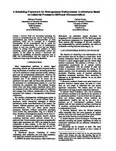
4. Parallel Rendering by Screen-space Subdivision We now describe the scheme we use in Pxpl5 to attain high levels of performance in a compact, modular, expandable machine. Our previous work has depended on a single, large computing surface of SIMD parallel processors operating on the entire screen space. In the new architecture, we instead have one or more small SIMD engines, called Renderers, that operate on small, separate 128x128-pixel patches in a virtual pixel space. Virtual patches can be assigned on the fly to any actual patch of the display screen. The system achieves considerable speedup by simultaneously processing graphics primitives that fall entirely within different patches on the screen.
I) I)
b '3
typical I / 128x128 ~pixel patch
1280 pixels Figure 1: Rendering process for a Pxpl5 system with 4 Renderers. 1280x1024 screen is divided into 80 128x128 patches. Patches are processed in raster order. Renderers a-d are assigned initially to the first four patches. Renderer a completes first, and is assigned to the next available patch. Next Renderer d completes its first patch and is assigned to the next available patch, and so forth. is new about this implementation is the idea of flexibly mapping small virtual pixel spaces onto the screen space. It allows useful systems to be built with any number of small rendering units, permits cost/performance to be traded nearly linearly, and can render into a window of arbitrary size with only linear time penalty. The virtual pixel approach is supported in the Pxpl5 implementation by a memory hierarchy, whose elements are: (I) 208 bits of fast SRAM associated on-chip with each pixel processor; (2) a "backing store" built from VRAMs, tightly linked to the custom logic-enhanced memory chips; (3) a conventional V R A M frame buffer. The backing store consists •f an array of VRAMs, each connected via its video port to one of our custom memory chips; IMB VRAMs provide 4Kbits of storage per pixel. The backing store memory is available through the V R A M random I/O port to the rest of the system, which can read and write pixel values in the conventional way. A Renderer uses this memory to save and retrieve pixel values, effectively allowing "context switches" when the Renderer ceases operations on one patch and moves to another. A typical context switch takes about 0.4 msec, the time to render a hundred or so primitives, and can be fully overlapped with pixel processing.
The principal cost of this screen-space subdivision scheme is that the primitives handled in the transformation engine must be sorted into "bins" corresponding to each patch-sized region of the screen space. Primitives that fall into more than one region are placed into the bins for all such regions. The simplest (though expensive) way to support these bins is to provide additional storage in the transformation engine for the entire, sorted list of output primitives. Once transformed, sorted, and stored, a new scene is rendered by assigning all available Renderers to patches on the screen and dispatching to these Renderers primitives from their corresponding bins. When a Renderer completes a patch, it can discard its z-buffer and all other pixel values besides colors; pixel color values are transferred from on-chip pixel memory to the secondary storage system, or "backing store", described below. The Renderer is then assigned to the next patch to be processed. This process is illustrated in Figure 1 for a system configured with only four Renderers.
In the simple multi-Renderer scheme described above, the backing store is used to store pixel color values for patches of the screen as the Renderer completes them. When the entire image has been rendered, each of these regions is transferred in a t~lock to the (double-buffered) display memory in the Frame Buffer, from which the display is refreshed.
The general idea of multiple independent groups ofpixel processors operating on disjoint parts of the display screen was described in several of our earlier publications as "buffered" Pixel-Planes. What
5. Architectural Overview The major elements of Pxpl5 are: •
Graphics Processors (GPs), floating point engines, each with considerable local code and data storage.
•
Renderers, each a small SIMD array of pixel processors with its own controller.
•
Frame Buffer, double-buffered, built from conventional Video RAMs, from which the video display is refreshed. 81
~~(SG lGRAPH
'89, Boston, 31 July-4 August, 1989
5.2 Graphics Processors
pOrtl o,, :, ,_ : , C~l~,