This thesis proposes a new multi-aperture synthetic aperture radar (MASAR) au- tomatic target detection (ATD) algorithm that uses hidden Markov models ...
Hidden Markov Models for Multi-aperture SAR Target Detection A Thesis Presented in Partial Ful llment of the Requirements for the Degree Master of Science in the Graduate School of The Ohio State University by Layne R. Flake, B. S. ***** The Ohio State University 1995 Master's Examination Committee: Ashok K. Krishnamurthy Stanley C. Ahalt
Approved by Adviser Department of Electrical Engineering
THESIS ABSTRACT THE OHIO STATE UNIVERSITY GRADUATE SCHOOL NAME: Flake, Layne R. DEPARTMENT: Electrical Engineering
QUARTER/YEAR: SP 95 DEGREE: M. S.
ADVISER'S NAME: Krishnamurthy, Ashok K. and Ahalt, Stanley C. TITLE OF THESIS: Hidden Markov Models for Multi-aperture SAR Target Detection
This thesis proposes a new multi-aperture synthetic aperture radar (MASAR) automatic target detection (ATD) algorithm that uses hidden Markov models (HMMs) to exploit the anisotropic nature of radar returns from man-made objects. Speci c HMM structures are developed to represent target and clutter pixels based on the way their radar returns vary at di�erent aspect angles. The HMM ATD algorithm is subjected to a preliminary evaluation using simulated MASAR imagery. The HMM ATD algorithm displays better detection accuracy than the best alternative ATD method while requiring at least two orders of magnitude less calculations.
Adviser's Signature Department of Electrical Engineering
Acknowledgments I thank my advisers, Dr. Ashok Krishnamurthy and Dr. Stanley Ahalt, for the guidance which has made this research successful. They have been good examples of the type of professor that I someday hope to become. Dr. Lee Potter has also given me many helpful suggestions and has put endless work into forming a world-class synthetic aperture radar research group. I am grateful to Ed Riegelsberger for his comments. I want to thank The Ohio State University for giving me a University Fellowship and a position as a Graduate Research Assistant which have allowed me to pursue my studies. I also want to thank the Air Force's Wright Laboratory for providing the simulated radar data and the research grant which made this work possible. Finally, I thank Sarah, my wife, for all that she has done to allow me to achieve this great goal.
ii
Vita 24 August 1968 : : : : : : : : : : : : : : : : : : : : : : : Born{Arlington, Texas 1986 : : : : : : : : : : : : : : : : : : : : : : : : : : : : : : : : : National Merit Scholar 1986 { 1992 : : : : : : : : : : : : : : : : : : : : : : : : : : Trustees' Scholar, Brigham Young University, Provo, Utah 1987 { 1989 : : : : : : : : : : : : : : : : : : : : : : : : : : Missionary Service, The Church of Jesus Christ of Latter-day Saints, Rosario, Argentina 1991 { 1992 : : : : : : : : : : : : : : : : : : : : : : : : : : Software Technical Support Intern, IBM Corporation, Southlake, Texas 1992 { 1993 : : : : : : : : : : : : : : : : : : : : : : : : : : Edwin S. Hinckley Scholar, Brigham Young University, Provo, Utah August 1993 : : : : : : : : : : : : : : : : : : : : : : : : : : B.S. Electrical Engineering, Magna Cum Laude, Brigham Young University, Provo, Utah 1993 { 1994 : : : : : : : : : : : : : : : : : : : : : : : : : : University Fellow, The Ohio State University, Columbus, Ohio 1994 { present : : : : : : : : : : : : : : : : : : : : : : : : Graduate Research Associate, Department of Electrical Engineering, The Ohio State University, Columbus, Ohio
iii
Publications L. R. Flake, A. K. Krishnamurthy, and S. C. Ahalt, \Progress Report: MultiAperture SAR Target Detection Using Hidden Markov Models," Technical Report TR-94-02, The Ohio State University, Department of Electrical Engineering, SPANN Laboratory, November 1994. L. R. Flake, A. K. Krishnamurthy, and S. C. Ahalt, \Current Results: MultiAperture SAR Target Detection Using Hidden Markov Models," Technical Report TR-95-02, The Ohio State University, Department of Electrical Engineering, SPANN Laboratory, March 1995. L. R. Flake, A. K. Krishnamurthy, and S. C. Ahalt, \Multi-aperture SAR Target Detection Using Hidden Markov Models," in Proceedings of the SPIE International Symposium on Algorithms for Synthetic Aperture Radar Imagery II (D. A. Giglio, ed.), vol. 2487, Orlando, Florida, April 1995.
Fields of Study Major Field:
Electrical Engineering
Studies in:
Signal Processing, Digital Design, Computer Architecture
iv
Table of Contents ACKNOWLEDGMENTS : : : : : : : : : : : : : : : : : : : : : : : : : : : : : ii VITA : : : : : : : : : : : : : : : : : : : : : : : : : : : : : : : : : : : : : : : : iii LIST OF FIGURES : : : : : : : : : : : : : : : : : : : : : : : : : : : : : : : : vii LIST OF TABLES : : : : : : : : : : : : : : : : : : : : : : : : : : : : : : : : : ix CHAPTER
PAGE
INTRODUCTION : : : : : : : : : : : : : : : : : : : : : : : : : : : : : :
1
1.1 SAR ATD Overview : : : : : : : : : : : : : : : : : : : : : : : : : : 1.2 ATD Performance Metrics : : : : : : : : : : : : : : : : : : : : : : : 1.3 Thesis Organization : : : : : : : : : : : : : : : : : : : : : : : : : :
1 2 3
ADVANTAGES OF USING MASAR IMAGERY FOR ATD : : : : : : :
4
III ANALYSIS OF SIMULATED MASAR IMAGERY : : : : : : : : : : : :
8
I
II
IV MASAR HMM ATD ALGORITHM : : : : : : : : : : : : : : : : : : : : 14 4.1 Brief Introduction to HMMs : : : : : : : : : : : : : : : : 4.2 Details of the HMM ATD Algorithm : : : : : : : : : : : 4.2.1 O�-line Training Phase : : : : : : : : : : : : : : 4.2.2 On-line Detection Phase : : : : : : : : : : : : : : 4.3 HMM Structures for Modeling Sub-aperture Trajectories 4.3.1 Modeling Target Trajectories : : : : : : : : : : : 4.3.2 Modeling Clutter Trajectories : : : : : : : : : : : v
: : : : : : :
: : : : : : :
: : : : : : :
: : : : : : :
: : : : : : :
: : : : : : :
14 18 18 20 21 22 25
4.4 Why Use the HMM ATD Algorithm? : : : : : : : : : : : : : : : : : 26 V
EVALUATION OF HMM ATD ALGORITHM : : : : : : : : : : : : : : 28 5.1 Evaluation of Detection Accuracy : : : : : : : : : : : : 5.1.1 HMM Detection Experimental Procedure : : : 5.1.2 CFAR Detection Experimental Procedure : : : 5.1.3 SA Change Detection Experimental Procedure 5.1.4 Detection Accuracy Results : : : : : : : : : : : 5.2 Evaluation of Computational E�ciency : : : : : : : : 5.3 Detection Using a Restricted Angle of Integration : : :
: : : : : : :
: : : : : : :
: : : : : : :
: : : : : : :
: : : : : : :
: : : : : : :
: : : : : : :
28 28 29 31 34 37 39
VI DISCUSSION : : : : : : : : : : : : : : : : : : : : : : : : : : : : : : : : : 44 APPENDICES A
M -ARY NEYMAN-PEARSON TEST : : : : : : : : : : : : : : : : : : : 48
B
CALCULATIONS REQUIRED FOR EACH TDLMS ITERATION : : : 50
C
CLUSTERING ALGORITHM : : : : : : : : : : : : : : : : : : : : : : : : 53
REFERENCES : : : : : : : : : : : : : : : : : : : : : : : : : : : : : : : : : : : 56
vi
List of Figures
FIGURE
PAGE
1
Block Diagram of a Typical ATR System : : : : : : : : : : : : : : : :
2
2
MASAR Image Formation : : : : : : : : : : : : : : : : : : : : : : : :
5
3
Comparison of Target and Clutter Sub-aperture Trajectories : : : : : 10
4
Sub-aperture Glint Angles for Pixels of an M35 Truck : : : : : : : : : 11
5
Average Target, Grass, and Tree Sub-aperture Trajectories : : : : : : 13
6
3-state HMM Corresponding to Example Urns and Balls System : : : 16
7
Block Diagram of O�-line HMM Training : : : : : : : : : : : : : : : : 19
8
Block Diagram of On-line HMM Detection : : : : : : : : : : : : : : : 20
9
7-state Left-right HMM Structure : : : : : : : : : : : : : : : : : : : : 22
10 HMM Structure with Parallel 7-state Paths : : : : : : : : : : : : : : 23 11 Example Circular Target HMM : : : : : : : : : : : : : : : : : : : : : 24 12 Diagram of Two-parameter CFAR Detection : : : : : : : : : : : : : : 30 13 Block Diagram of SA Change Detection : : : : : : : : : : : : : : : : : 32 14 SA Change Detection Extended to N Sub-apertures : : : : : : : : : : 33 15 Single-pixel Detection Results : : : : : : : : : : : : : : : : : : : : : : 35 16 Example Output of Post-detection Clustering Algorithm : : : : : : : 41 vii
17 Clustered Detection Results : : : : : : : : : : : : : : : : : : : : : : : 42 18 Clustered Detection Results (Restricted Angle of Integration) : : : : 43 19 Comparison of All HMM Clustered Detection Results : : : : : : : : : 46 20 Operation of the TDLMS Adaptive Filter : : : : : : : : : : : : : : : : 51
viii
List of Tables
TABLE 1
PAGE Computational E�ciency of Each ATD Method : : : : : : : : : : : : 39
ix
CHAPTER I INTRODUCTION Multi-aperture synthetic aperture radar (MASAR) imagery is an extension of conventional synthetic aperture radar (SAR) imagery that enables automatic target detection (ATD) algorithms to exploit the anisotropic nature of radar returns from man-made objects. In this thesis, a new MASAR ATD algorithm based on hidden Markov models (HMMs) is proposed. The HMM ATD algorithm is subjected to a preliminary evaluation using simulated MASAR imagery containing 8 M35 trucks as targets, interspersed among trees on a grassy plain. In terms of performance, the HMM ATD algorithm is compared with two alternative ATD methods: 1) MASAR split-aperture (SA) change detection and 2) two-parameter constant false alarm rate (CFAR) detection.
1.1 SAR ATD Overview The goal of SAR ATD is to use computational methods to automatically decide (detect) if one or more objects of interest (targets) are present in a ground scene based on data collected by a SAR sensor. If targets are present, the ATD algorithm 1
2 Input Prescreener
Image
Discriminator
Classifier
Rejects Imagery Without
Rejects Natural-Clutter
Rejects Man-Made
Potential Targets
False Alarms
Clutter
Classifies Targets
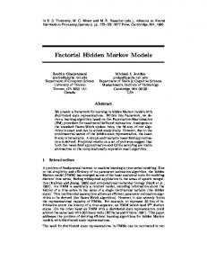
Figure 1: Block diagram of a typical ATR system. should determine their location within the SAR image. ATD is generally used as a rst step in automatic target recognition (ATR). The block diagram of a typical ATR system is shown in Figure 1 [1]. The rst block is a prescreener which uses ATD methods to nd possible target pixels within an image. The second block is a discriminator which rejects false alarms caused by trees and other naturallyoccurring clutter. The third block is a classi er which attempts to identify the type of target which has been found. The HMM ATD algorithm and the alternative ATD methods examined in this thesis are designed for usage in the prescreener stage of an ATR system.
1.2 ATD Performance Metrics Two ATD performance metrics will be considered in this thesis: 1) detection accuracy and 2) computational e�ciency. ATD algorithms are designed for high detection accuracy so that they detect as many targets as possible while minimizing the number of false alarms passed to the computationally intensive later stages of
3 the ATR system. ATD algorithms are designed for computational e�ciency so that they can process large amounts of image data before the images are invalidated by changes in the ground situation. This thesis evaluates the detection accuracy and computational e�ciency of the HMM ATD algorithm and the alternative ATD methods by performing detection on simulated MASAR imagery which has known target locations.
1.3 Thesis Organization Chapter II explains the advantages of using MASAR imagery instead of SAR imagery for ATD. Chapter III analyzes the anisotropic radar returns present in the simulated MASAR imagery. Chapter IV provides a brief introduction to HMMs and presents the HMM ATD algorithm. Chapter V compares the detection performance of the HMM, SA change detection, and CFAR ATD algorithms. Finally, Chapter VI presents conclusions derived from this research and describes promising directions for future study.
CHAPTER II ADVANTAGES OF USING MASAR IMAGERY FOR ATD MASAR imagery is formed using the radar returns from a ground patch collected by a SAR sensor. However, instead of using the full set of radar returns to form a single SAR image, MASAR divides the radar returns into equally-sized, non-overlapping subsets, as shown in Figure 2. A standard SAR image formation algorithm [2, 3] is applied to each radar return subset, producing multiple sub-aperture images.1 Thus, each sub-aperture image represents the radar re ectivity of the ground patch when it is viewed from a di�erent range of aspect angles. Since the sub-aperture images are all derived from the same SAR data collection interval, the images are perfectly co-registered. A basic assumption made in SAR image formation is that the radar returns from any given point in a ground patch will be isotropic; i.e. the returns will remain constant for all the aspect angles in the SAR data collection interval [2, 1
MASAR imagery is referred to as \Wide-Angle Synthetic Aperture Radar (WASAR)" by Knurr [4]. This terminology should be avoided because it does not emphasize that multiple sub-aperture images are formed. The term \Wide-Angle Synthetic Aperture Radar" is too easily confused with conventional SAR systems that collect radar returns over a wide range of aspect angles and form only one output image. Other researchers refer to MASAR imagery as \aspect-angle-diverse images" [5], which is a more accurate description.
4
5
Flight Path
Sub-aperture return sets
x Ground Patch
y
Figure 2: MASAR divides the SAR radar returns into equally-sized, non-overlapping subsets and forms a sub-aperture image from each one. 3]. This assumption allows SAR images to be formed using radar returns over a range of aspects. However, real-world objects re ect radar di�erently when it impinges on them from di�erent directions [6, 5, 7, 8]. Thus, radar returns are actually anisotropic, meaning that they vary as the aspect angle changes. Manmade objects usually have radar returns that are much more anisotropic than those from natural objects. A particular characteristic of man-made objects is that they may exhibit a high-intensity return known as a glint or ash for certain narrow aspect ranges. (One example is the glint caused by returns from the side panels of a truck that is exactly broadside to the SAR sensor.) Since SAR ATD algorithms
6 typically perform detection based on the intensity di�erence between target and natural clutter returns, glints are an important distinguishing feature of man-made targets. SAR imagery is formed by considering all of the radar returns collected by the SAR sensor to be of equal importance. Since glints occur for only narrow ranges of aspect angles, they are represented in only a small number of the radar returns. Thus, conventional SAR image formation \averages out" target glints so that the SAR image displays only a diminished version of the glint. In general, as the SAR data collection interval increases in length, more and more non-glint returns are collected, and the SAR image represents the target glint less and less. Due to the isotropic assumption inherent in SAR image formation, a longer data collection interval may lead to reduced SAR ATD performance. In contrast, MASAR image formation divides up the radar returns from di�erent aspect angles into nonoverlapping subsets. When sub-aperture images are formed using the radar return subsets, target glints are less diminished than they would be in the full-aperture SAR image, because each sub-aperture image is formed from a smaller aspect range. Another advantage of MASAR imagery is that the sub-aperture images show how the radar returns from the ground patch change as the aspect angle changes.2 Since 2
One of the important issues which has not yet been resolved for MASAR imagery is the question of how many sub-aperture images should be formed from the full set of radar returns. As the number of sub-aperture images increases, each image is formed from fewer radar returns. Thus, in general, the radar returns in each sub-aperture are more isotropic and the resulting subaperture images are more accurate. However, the cross-range resolution of each sub-aperture image decreases as the number of radar returns in each sub-aperture shrinks. Also, the total processing time required to form the sub-aperture images increases. For the purposes of this thesis, the sub-aperture images are simply assumed to be as accurate as possible.
7 the sub-aperture images are co-registered, values are extracted from the images to form sub-aperture trajectories for each image pixel. For MASAR imagery having N sub-apertures, the sub-aperture trajectory for each pixel is a sequence of the form
y[k] = y[1]; y[2]; : : : ; y[N ]
(2.1)
where y[i] is the pixel's value in sub-aperture image i. The sub-aperture trajectories preserve information about anisotropic radar returns that would be discarded if a SAR image were formed from the full set of radar returns. Even though the sub-aperture images have reduced cross-range resolution because they are formed from fewer radar returns [2, 3], the addition of anisotropic radar return information and the improved representation of target glints make it possible for MASAR ATD algorithms to achieve higher detection accuracies than conventional SAR ATD algorithms.
CHAPTER III ANALYSIS OF SIMULATED MASAR IMAGERY The simulated imagery used in this research is a MASAR view of a single ground patch that has been generated by the Xpatch-es program developed by Loral [4]. The MASAR image displays 8 M35 trucks at random orientations in grass and trees, with 25% of the image area forested. The radar returns used to form the MASAR image have a center frequency of 1.2 GHz (L-band) and are collected over a 105� angle of integration at a 15� depression angle. The 105� synthetic aperture is divided into 7 sub-apertures, each 15� wide. The MASAR image is formed from multiple polarimetric returns such that each sub-aperture image has complex-valued
HH , HV , and V V components. The resolution of each sub-aperture image is 2 ft
� 2 ft, with pixel sample spacing of 1.6 ft � 1.6 ft. At this pixel sample spacing, the M35 trucks are approximately 5 pixels � 14 pixels. Each sub-aperture image is 360 pixels � 360 pixels. The simulated MASAR image is analyzed to investigate the e�ects of anisotropic radar returns. Since the target and tree locations are known, the image is handdivided into regions containing target, tree clutter, and grass clutter pixels. Since 8
9 the MASAR image is multi-polariy, the sub-aperture trajectories for each pixel are sequences of the form
0 1 0 1 0 1 yHH [1] yHH [2] yHH [7] y[k] = B@ yHV [1] CA ; B@ yHV [2] CA ; : : : ; B@ yHV [7] CA yV V [1] yV V [2] yV V [7]
(3.1)
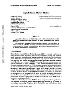
where each 3-tuple contains the pixel's multiple polarity values for a speci c subaperture. To simplify the analysis of sub-aperture trajectories, the polarimetric whitening lter (PWF) developed by Novak, et. al. [9] is applied to each trajectory. The PWF uses the multiple polarity values in each 3-tuple to estimate the overall radar return intensity at each sub-aperture in the trajectory. The e�ect of anisotropic radar returns on individual sub-aperture trajectories is shown in Figure 3, which compares the PWF-derived intensity trajectories for a target pixel, a tree pixel, and a grass pixel. Anisotropic returns cause the target trajectory to exhibit a high-intensity glint in the 0� sub-aperture. The target trajectory values also vary more as a function of sub-aperture angle than the tree and grass trajectory values. Almost all target trajectories in the MASAR image display a glint like the one shown in Figure 3, while only a few tree trajectories display intensity peaks of this magnitude and no grass trajectories display such peaks. Many target trajectories also show one or two lower-intensity peaks, like the target trajectory's lesser peak in Figure 3. For the case shown in the gure, the target trajectory has a lower mean intensity than the tree trajectory, despite having a high-intensity glint. Thus, an ATD algorithm that operates on the \averaged" intensities that result from conventional SAR image formation may not be able to discriminate between these two pixels. In contrast, an ATD algorithm that takes advantage of the anisotropic glint
10 Example Intensity Trajectories 250
PWF Intensity
200
Target Trajectory (mean = 64.4) Tree Trajectory (mean = 94.4)
150
Grass Trajectory (mean = 0.3)
100
50
0 −50
−40
−30
−20
−10 0 10 20 Sub−aperture Angle (Degrees)
30
40
50
Figure 3: Sub-aperture trajectories comparing the change in radar return intensity vs. sub-aperture angle for a target pixel, a tree pixel, and a grass pixel. which is preserved by MASAR image formation will correctly detect the target pixel and suppress the tree pixel false alarm. Many researchers have assumed that the only glints exhibited by target pixels occur when the entire target is broadside to the SAR sensor [7, 8, 6]. However, analysis of the target trajectory glints in the simulated MASAR image contradicts this assumption. For each of the M35 trucks, not even a majority of the target trajectory glints occur in the broadside sub-aperture. For example, the diagram in Figure 4 shows the sub-aperture glint angles for each pixel of one of the M35 trucks. Although this truck is broadside to the SAR sensor in the 0� sub-aperture, 50 out of the 70 glints occur at one of the other 6 sub-aperture angles. Instead of just
11
Direction of SAR Sensor 30 −15
−45 0
−30 −45 0
−45 −30
0
30
45 15 −30 −45 30
30
−45 45
45
45
−30 −45
30
30
Figure 4: Diagram showing the sub-aperture glint angles for each pixel of one of the M35 trucks in the simulated MASAR image. The truck is broadside to the SAR sensor at a 0� sub-aperture angle. containing broadside glints, the target trajectories display glints that result from the local geometry of di�erent parts of the target. To investigate the overall anisotropic behavior of each trajectory class, the average target, tree, and grass sub-aperture trajectories are found. So that only anisotropic behavior will be displayed, the mean value of each individual trajectory is subtracted out before averaging. The individual trajectories are also shifted before averaging so that their peak intensities occur at the same relative sub-aperture angle. By following this procedure, all of the target trajectories are averaged together, as well as random samples of 400 grass and 400 tree trajectories. The average target, grass, and tree trajectories are plotted in Figure 5. The plots include error bars superimposed at each relative sub-aperture angle to show �1 standard deviation of the values at that angle. Note that the anisotropic behavior of the target trajectories follows a common sequential pattern. In general, this pattern consists of a sequence
12 of one or more normal-intensity returns, a high-intensity, single-return glint, and then one or more normal-intensity returns. In contrast, grass and tree trajectories do not follow this pattern.
13
PWF Intensity
PWF Intensity
PWF Intensity
Average Target Pixel Trajectory 800 600 400 200 0 −200 −80
−60
−40
−20 0 20 40 Relative Angle (Degrees) Average Tree Pixel Trajectory
60
80
−80
−60
−40
60
80
−80
−60
−40
60
80
800 600 400 200 0 −200 −20 0 20 40 Relative Angle (Degrees) Average Grass Pixel Trajectory
800 600 400 200 0 −200 −20 0 20 40 Relative Angle (Degrees)
Figure 5: Plots of the average target, grass, and tree trajectories with error bars of
�1 standard deviation superimposed. Before averaging, the trajectories are shifted so that their peak intensities occur at the same relative sub-aperture angle.
CHAPTER IV MASAR HMM ATD ALGORITHM HMMs are a stochastic method of signal representation that has proven useful for text analysis, coding theory, cryptanalysis, speech recognition, and general temporal pattern recognition problems. As far as we know, HMM methods have not previously been applied to SAR ATD. This chapter begins with a brief summary of HMM concepts before presenting the details of the HMM ATD algorithm. For a more complete treatment of HMMs, the reader is referred to the tutorials in [10, 11, 12].
4.1 Brief Introduction to HMMs To introduce the idea of an HMM, consider a hypothetical system patterned after the example given in [11]. Suppose that three urns are lled with di�erent mixtures of red and blue balls and are placed on a stage such that they are hidden from the audience by a curtain. A genie working behind the curtain chooses one of the urns according to some probability distribution, chooses a ball from that urn at random, and then carries the ball forward to show its color to the audience. The genie then replaces the ball, chooses the next urn according to a probability distribution 14
15 associated with the current urn, and selects a ball to show the audience from the next urn. As this process repeats, two random sequences result: 1) the sequence of urns chosen by the genie and 2) the sequence of colors observed by the audience. The sequence of urns chosen by the genie is a 1st-order Markov sequence because the probability of each urn being selected as the next urn solely depends on which is the current urn. Further, this can be termed a \hidden" Markov sequence because the selection of urns is hidden from the audience. Since each urn contains a di�erent distribution of red and blue balls, the observed sequence of colors is in uenced by the urn sequence. However, the color sequence does not directly correspond to any particular urn sequence because there are red and blue balls in all of the urns. The hypothetical system which has just been described is equivalent to the 3-state HMM diagrammed in Figure 6. In general, an HMM is formed by joining together two stochastic processes. One of the processes must be a stationary, discrete-time, discrete-state 1st-order Markov process. The sample functions of the Markov process are random sequences x[k] for
k = 1; 2; : : : ; T . For a speci c k, x[k] is equal to an integer in the range 1 � x[k] � N which denotes the state of the process at time k. Since x[k] is stationary, its statistics can be fully de ned by specifying three quantities: 1. N , the number of states. 2. A = fa(i; j )g, the N � N state transition probability matrix, where
a(i; j ) = P fx[k + 1] = j j x[k] = ig
(4.1)
16 a2,2 a1,1 a1,2 State 2 (Urn 2)
a2,1
State 1 (Urn 1)
a1,3
a2,3 a3,2
a3,1 State 3 (Urn 3)
Output Probability Matrix
a3,3
b1,red
b1,blue
b2,red
b2,blue
b3,red
b3,blue
Figure 6: State diagram of a 3-state HMM that corresponds to the example urns and balls system. 3. � = f�(i)g, the N -element initial state probability vector, where
�(i) = P fx[1] = ig
(4.2)
The x[k] sequence corresponds to the sequence of urns chosen by the genie in the hypothetical system outlined above. The other stochastic process is the output of the HMM, which has sample functions denoted by O[k] for k = 1; 2; : : : ; T . To generate O[k], each state of x[k] is assigned an output probability distribution. At each time k, the value of O[k] is chosen according to the probability distribution that corresponds to the current state x[k]. As a result, the HMM output sequence
17
O[k] \hides" x[k]. In terms of the hypothetical system, O[k] corresponds to the color sequence observed by the audience. To specify the HMM output probabilities, two more quantities are required in addition to N , A, and �: 1. M , the number of discrete output symbols.1 2. B = fb(i; j )g, the N � M output probability matrix, where
b(i; j ) = P fO[k] = j j x[k] = ig
(4.3)
As a compact representation, an HMM can be expressed by �(A; B; �). In HMM applications, it is desirable to know the probability that an HMM will generate a particular output sequence. The generation probability is a function of the output sequence O[k] and the HMM parameters A, B , and �. Using the shorthand notation introduced earlier, the generation probability for an HMM �(A; B; �) is written as f (Oj�). This probability may be computed exactly using the forwardbackward procedure or may be estimated using the Viterbi algorithm2 [11]. The crucial requirement for HMM applications to be e�ective is the ability to design an HMM that will represent a speci c signal class. This is the problem of estimating the A, B , and � parameters which cause the HMM's output sequences to approximate the desired signals. The HMM parameter estimation problem cannot The HMMs described in this thesis are all discrete-output HMMs. Researchers have also described continuous-output HMMs, where the output at each state is de ned by a continuous probability distribution [11]. 2 The Viterbi algorithm nds the state sequence which is most likely to generate O[k]. The Viterbi algorithm then uses the probability that O[k] is generated by that speci c state sequence as an estimate of f (O �). In contrast, the forward-backward procedure computes the exact generation probability by nding the total probability that O[k] was generated by any one of the possible HMM state sequences.
1
j
18 be solved analytically. However, methods exist to iteratively optimize A, B , and
� so that an HMM is likely to generate output sequences which are drawn from a set of example sequences. Once an HMM � has been trained to represent a speci c signal class, the generation probability f (Yj�) for an unclassi ed signal Y[k] is used to measure the likelihood that the signal belongs to the class represented by �.
4.2 Details of the HMM ATD Algorithm The HMM ATD algorithm uses HMMs to model the MASAR sub-aperture trajectories corresponding to target and clutter pixels. During an o�-line training phase, one HMM is trained to represent target trajectories and one or more HMMs are trained to represent clutter trajectories. (Multiple clutter HMMs provide robustness when MASAR imagery contains a mixture of di�erent clutter types, such as when both grass and tree clutter are present.) After training is complete, detection is performed by presenting an unclassi ed pixel's sub-aperture trajectory to all of the HMMs in parallel. A decision statistic is computed based on the HMM generation probabilities. If the decision statistic is greater than a xed threshold, the algorithm decides that the pixel is a target pixel.
4.2.1 O�-line Training Phase Figure 7 shows a block diagram of the o�-line training phase of the HMM ATD algorithm, which requires example target and clutter sub-aperture trajectories. The
19 Target Example Sequences
Quantize
Baum-Welch Reestimation
HMM Parameters (A, B, pi)
Target HMM
Clutter Class 1 Example Sequences
Quantize
Baum-Welch Reestimation
HMM Parameters (A, B, pi)
Clutter 1 HMM
Clutter Class 2 Example Sequences
Quantize
Baum-Welch Reestimation
HMM Parameters (A, B, pi)
Clutter 2 HMM
. . .
. . .
Quantize
Baum-Welch Reestimation
Clutter Class N Example Sequences
. . . HMM Parameters (A, B, pi)
Clutter N HMM
Figure 7: Block diagram of o�-line HMM training performed to estimate target and clutter HMM parameters. simplest way to obtain the example trajectories is to extract them from MASAR imagery that has known target and clutter pixels. Since the HMM outputs are drawn from a nite set of M output symbols, the radar return values forming each example trajectory are quantized before HMM training is performed. (Scalar quantization is used for single-polarity MASAR imagery and vector quantization is used for multipolarity MASAR imagery.) After the A, B , and � parameters of each HMM are given random initial values, the Baum-Welch reestimation method iteratively optimizes the parameters until the HMM represents the example trajectories [13, 14, 11].
20 Target HMM Parameters
Viterbi Algorithm
^ f(Y[k] | targ)
Clutter 1 HMM Parameters
Viterbi Algorithm
Quantized Test Sequence
^ f(Y[k] | clut1) Threshold
^ f(Y | targ)
Clutter 2 HMM Parameters
^ ^ f(Y | clut1) + f(Y | clut2) +
. . .+ ^f(Y | clutN)
>K
Decision
Y[k] Viterbi Algorithm
^ f(Y[k] | clut2)
. . . Clutter N HMM Parameters
Viterbi Algorithm
^ f(Y[k] | clutN)
Figure 8: Block diagram of on-line HMM detection using target and clutter HMMs trained previously.
4.2.2 On-line Detection Phase Figure 8 shows a block diagram of the on-line detection phase of the HMM ATD algorithm, which uses the target and clutter HMM parameters which have been found by the training phase. Let Y[k] for k = 1; 2; : : : ; T be the sub-aperture trajectory corresponding to an unclassi ed MASAR image pixel. As with HMM training, the radar return values in Y[k] must rst be quantized to the nite set of
M HMM output symbols. Next, the Viterbi algorithm estimates the probabilities
21 that Y[k] was generated by each HMM.3 The generation probability estimates are written as
f^(Yj�targ )
(4.4)
f^(Yj�clut1 ); f^(Yj�clut2 ); : : : ; f^(Yj�clutN )
(4.5)
and for N clutter HMMs. Assuming that the target and clutter HMMs have been trained to accurately represent their respective signal classes, the following decision statistic is computed:
f^(Yj�targ ) �(Y) = ^ f (Yj�clut1 ) + f^(Yj�clut2 ) + � � � + f^(Yj�clutN )
(4.6)
If �(Y) is greater than a xed threshold K , the HMM ATD algorithm decides that the MASAR image pixel is a target pixel. The decision statistic �(Y) is designed to implement an M -ary Neyman-Pearson hypothesis test based on the estimated HMM generation probabilities. The M -ary Neyman-Pearson test is derived in Appendix A.
4.3 HMM Structures for Modeling Sub-aperture Trajectories The structure of an HMM, as de ned by its allowable state transitions, is an integral part of its design. In general, an HMM structure that re ects the overall properties of a signal class requires less training and represents the signal class more accurately. 3
Better performance has been observed with the Viterbi-estimated probabilities than with the exact probabilities computed by the forward-backward procedure. Most HMM detection systems are implemented using the Viterbi algorithm [11, 12].
22
Beginning State
Ending State
Figure 9: State diagram of the 7-state left-right HMM structure. This section discusses speci c HMM structures which are used to represent target and clutter MASAR sub-aperture trajectories.
4.3.1 Modeling Target Trajectories Target trajectories are distinguished from clutter trajectories by the sequential anisotropic pattern observed in Chapter III. In speech recognition applications, researchers have found that the left-right HMM structure accurately models signals that follow a sequential pattern [15, 16, 17]. One version of the left-right structure speci es state 1 as a common beginning state and only allows a transition from state
k to state k +1 at each discrete time interval. Figure 9 shows the state diagram for a 7-state left-right HMM of this type. Since its states are visited according to a strict order, the left-right HMM is clearly capable of representing the sequential pattern found in target trajectories. It represents target trajectories by using the output probability distribution of state k to represent all the possible target pixel values for the kth sub-aperture. However, since glints in the target trajectories can occur in any sub-aperture, the output probability distribution in each state has a high variance, and the HMM does not take full advantage of the sequential anisotropic
23
Choose One Path
. . .
. . .
. . .
Figure 10: HMM structure which merges multiple 7-state left-right HMMs in parallel. behavior of target trajectories. The target glint misalignment problem is resolved by merging multiple 7-state left-right HMMs to form the parallel HMM structure shown in Figure 10. In the parallel HMM structure, each of the state paths represents target trajectories which have glints that occur in the same sub-aperture. When the Viterbi algorithm estimates the probability that a parallel HMM generates a given trajectory, it only considers the state path which best represents the trajectory. Thus, if there are 7 state paths and each is trained to represent glints occurring in a di�erent sub-aperture, this structure automatically aligns any target trajectory to take full advantage of its anisotropic behavior. However, due to variabilities in target HMM training, an HMM with more than 7 parallel paths is usually required to ensure that all possible glint angles are represented. One drawback of the parallel HMM structure is that the number of states increases rapidly as the number of parallel paths increases. For example, a 12-path parallel HMM requires 84 states. This means that an increased number of training
24
Choose First State
Figure 11: An example 8-state circular target HMM. examples is needed to accurately estimate the output probability distributions for all the states. To resolve this problem, target trajectories are modeled with the circular HMM structure, which maintains the advantages of the parallel HMM structure while achieving greater training e�ciency. The state diagram of an 8-state circular HMM is shown in Figure 11. The circular HMM uses the observation that the non-glint values in the target trajectories displayed in Figure 5 are similar regardless of their sub-aperture angle. This means that only one of the states in the circular target HMM needs to represent sub-aperture glint values and the rest can represent non-glint values. By allowing the beginning state to be chosen from among all of the
25 states, each target trajectory is still automatically aligned so that its glint occurs in the state which represents glint returns. The circular HMM structure requires fewer training examples since there are fewer output probability distributions to estimate. The circular HMM is trained using the standard Baum-Welch reestimation method. For a given trajectory Y[k], the generation probability of an N -state circular target HMM �(A; B; �) is estimated in two steps using the Viterbi algorithm: 1. Find the probability that Y[k] is generated by each of the N possible state sequences according to the equation
0j +T ?1 1 Y f (Y j �; initial state j ) = �(j ) @ B (i mod N; Y [i ? j + 1])A (4.7) i=j
where T is the number of elements in Y[k]. 2. Choose the maximum value of f (Y j �; initial state j ) over j = 1; 2; : : : ; N to be the best estimate of f (Yj�).
4.3.2 Modeling Clutter Trajectories Ideally, the HMM structure used to model clutter trajectories should represent their isotropic radar returns while rejecting the sequential anisotropic returns found in target trajectories. However, all HMMs are inherently sequential by de nition, because their state sequences are 1st-order Markov processes. Thus, the HMM structure which best models clutter trajectories is the degenerate 1-state HMM, which has no state transitions. A 1-state HMM is fully de ned by a single output probability distribution P = fp(i)g, where p(i) is the probability that output symbol i
26 is generated. When used to model clutter trajectories, the 1-state HMM generates output symbols using the same P distribution regardless of the sub-aperture angle, thus requiring the clutter trajectories to be isotropic. A 1-state clutter HMM does not need to be trained using the Baum-Welch reestimation method. Instead, its P distribution is estimated to be equal to the frequency of occurrence of each output symbol in the example clutter trajectories. Since the example clutter trajectories are nearly isotropic, the estimated P distribution has a low variance. For a given trajectory Y[k], the generation probability of a 1-state clutter HMM �(P ) is computed using
f (Yj�) =
T Y k=1
p(Y [k])
(4.8)
where T is the number of elements in Y[k]. If Y[k] is a target trajectory with a glint occurring in the ith sub-aperture, p(Y [i]) will be small due to the P distribution's low variance. Thus, the product in Equation 4.8 will be small and the 1-state clutter HMM will reject the target trajectory. For HMM detection performed on the simulated MASAR imagery, tree and grass sub-aperture trajectories are represented using di�erent 1-state HMMs, since these clutter classes have very di�erent mean intensities. (See Figure 3.)
4.4 Why Use the HMM ATD Algorithm? The HMM ATD algorithm has three characteristics which enable it to achieve good detection performance:
27
1. Ability to Exploit Anisotropic Target Returns. By using a target HMM designed to represent the anisotropic pattern of target trajectories and clutter HMMs which reject this pattern, the HMM ATD algorithm achieves a high detection accuracy. 2. Computational E�ciency. Although the o�-line HMM training phase is computationally intensive, it only needs to be done once before HMM detection can be performed any number of times. The detection phase employs the e�cient Viterbi algorithm, which requires an amount of calculations that increases linearly with the number of HMM states [15]. 3. Ability to Use Multi-polarity Imagery. Through the use of vector quantization, the HMM detection algorithm can take advantage of multi-polarity MASAR imagery when it is available.
CHAPTER V EVALUATION OF HMM ATD ALGORITHM The HMM ATD algorithm is evaluated by comparing its performance with the performance of two alternative methods: 1) conventional SAR two-parameter constant false alarm rate (CFAR) detection and 2) MASAR split-aperture (SA) change detection. This chapter will rst explain how detection is performed on the simulated MASAR imagery using two di�erent versions of the HMM ATD algorithm and using the alternative ATD methods. The detection accuracies and computational e�ciencies achieved by the ATD methods will then be compared.
5.1 Evaluation of Detection Accuracy 5.1.1 HMM Detection Experimental Procedure HMM detection is performed using two di�erent versions of the HMM ATD algorithm. One version uses a 12-state circular target HMM and the other uses a 1-state target HMM. Both versions use the same 1-state target and grass HMMs. By comparing the results obtained with the di�erent target HMMs, the performance 28
29 di�erence that results from exploiting the anisotropic behavior of the target trajectories can be measured. The 1-state tree HMM is trained using example sub-aperture trajectories which correspond to 4000 tree pixels that have been chosen at random from the simulated MASAR image. Likewise, the 1-state grass HMM is trained using 4000 example grass trajectories that have been chosen at random. A leave-one-out method is used to train both target HMMs. Pixels from 7 targets (175 pixels) provide training trajectories while pixels from the remaining target (25 pixels) provide test trajectories. By performing leave-one-out target HMM training with a di�erent target left out each time, HMM detection is tested on all of the targets in the MASAR image. Since the 12-state circular target HMM relies on sequential patterns in the target trajectories, it performs di�erently when trajectory values are presented to it in reverse order. This allows the training and testing sets for the 12-state circular target HMM to be doubled by including both normally-ordered and reverse-ordered trajectories in them. The quantization required by both the training and detection phases of the HMM ATD algorithm is performed by a vector quantizer that maps the multi-polarity (HH , HV , V V ) values in the sub-aperture trajectories to a set of 96 codebook vectors.
5.1.2 CFAR Detection Experimental Procedure The two-parameter constant false alarm rate (CFAR) detector was rst developed by Goldstein for use on 1-D radar range pro les and was later extended for use
30
Guard Area (So Target Does Not Distort Clutter Estimation) M Cells
CFAR Clutter Reference Window
Target
Test Cell
M Cells
Figure 12: Diagram showing how the CFAR detector uses a ring of reference pixels to estimate the local clutter mean and variance. on SAR imagery by Novak, et. al [18, 9]. Although it is not a MASAR ATD algorithm, the CFAR detector proved better than several other conventional SAR ATD algorithms studied by Whitehead [6]. Thus, CFAR detection results provide a good comparison between MASAR detection performance and conventional SAR detection performance. As shown in Figure 12, the CFAR detector uses an M � M ring of reference pixels to estimate the local clutter mean �^t and standard deviation
�^t near each test pixel [1]. The reference pixels are separated from the test pixel by a guard area that must be large enough to ensure that if the test pixel falls on any part of a target, none of the reference pixels will fall on the same target. If the test
31 inequality
xt ? �^t > K �^t
(5.1)
is true, where xt is the amplitude of the test pixel, the pixel is labeled a target pixel. The CFAR detector is designed to operate on a single SAR image. An ideal comparison between CFAR detection and the HMM ATD algorithm would require CFAR detection to be performed on the SAR image formed using the complete set of simulated radar returns. However, due to peculiarities in the Xpatch-es simulation software, the full-aperture SAR image cannot be formed from the simulated data. Instead, the CFAR detector's performance is estimated by averaging together the results from performing CFAR detection on the individual sub-aperture images. Since the sub-aperture images are multi-polarity, the PWF mentioned in Chapter III is used to estimate an overall intensity image from the HH , HV , and V V components for each sub-aperture. CFAR detection is then performed on the PWF-derived sub-aperture images using a 29 � 29 ring of reference pixels.
5.1.3 SA Change Detection Experimental Procedure The split-aperture (SA) change detection algorithm was developed by Halversen, et. al [5]. Figure 13 shows a block diagram of SA change detection. SA change detection uses two sub-aperture images as input and performs single-pixel detection based on the magnitude di�erence between the two images. A robust image subtraction method, the two-dimensional least mean squares (TDLMS) algorithm, determines the magnitude di�erence at each pixel [19]. The input to the TDLMS
32 Sub-Aperture Image
Primary Image Reference Image
TDLMS Robust Image Subtraction
Difference Image A
Max Sub-Aperture Image
Primary Image Reference Image
TDLMS Robust Image Subtraction
Difference Image B
>K
Detections
Threshold
Figure 13: Block diagram of split-aperture (SA) change detection. algorithm consists of two co-registered images, the primary image D and the reference image X . The primary image D is considered to be a 2-D array which consists of the ideal image plus additive noise. The reference image X is a 2-D interference array such that the pixel values in X are spatially correlated with the noise component of the same pixels in D. The TDLMS algorithm iteratively estimates the additive noise component of each pixel in D using interference information from a local region of X that contains the pixel in D. After the estimated noise component at each pixel converges to a single value, this amount is subtracted from the pixel value in D to give the minimum-noise TDLMS di�erence image. When TDLMS image subtraction is used in SA change detection, target pixels (if any are present) are assumed to have higher amplitudes in the primary sub-aperture image D than in the reference sub-aperture image X . Since naturally-occurring clutter is nearly isotropic, the clutter (noise) returns in D and X are assumed to be correlated. Ideally, TDLMS image subtraction suppresses the clutter returns so that the TDLMS di�erence image has a much greater magnitude at target pixels than at clutter pixels. Since there is no way of knowing which of the sub-aperture
33 Sub-ap. #1
TDLMS
Sub-ap. #2
TDLMS
Sub-ap. #1
TDLMS
Sub-ap. #3 . . .
TDLMS . . .
Sub-ap. #N-1
TDLMS
Sub-ap. #N
TDLMS
Max
>K
Detections
. . . Threshold
Figure 14: Block diagram of SA change detection using N sub-aperture images. TDLMS image subtraction is performed on all possible combinations of the N images taken two at a time. images has stronger target returns, the TDLMS algorithm is performed twice. If the maximum of the two TDLMS di�erences for a pixel is greater than a threshold, it is labeled a target pixel. There are 7 sub-apertures in the simulated MASAR imagery. However, the SA change detection algorithm was originally designed for only two sub-apertures. As shown in Figure 14, SA change detection is extended to use MASAR imagery having N sub-apertures by performing TDLMS image subtraction on all possible combinations of the N sub-aperture images taken two at a time. The maximum of all the TDLMS di�erences for each pixel is compared to a threshold to decide if it is a target pixel. Since the simulated MASAR imagery is multi-polarity, SA change detection is performed on the same PWF-derived sub-aperture images that are used for CFAR detection. For the simulated MASAR imagery, a 2 � 2 TDLMS lter window and a gain constant of � = 0:01 were empirically observed to give the best
34 results. (See Appendix B for an explanation of the TDLMS parameters.)
5.1.4 Detection Accuracy Results The HMM, SA change detection, and CFAR ATD algorithms each perform detection one-by-one on all the pixels of a SAR image and return a set of detected target pixels. Since the actual target pixel locations are known, the single-pixel probability of detection (Pd ) and probability of false alarm (Pf ) are estimated for each ATD method using the following equations: of target pixels detected Pd = number total number of target pixels
(5.2)
of non-target pixels detected Pf = number total number of clutter pixels
(5.3)
Figure 15 compares the estimated receiver operating characteristic (ROC) curves obtained by the two versions of the HMM ATD algorithm with those obtained by the two alternative methods. The SA change detection and HMM ATD algorithms display virtually the same single-pixel detection accuracy. Surprisingly, the 1-state target HMM has a slightly better single-pixel detection accuracy than the 12-state circular target HMM. All three of the MASAR algorithms are far more accurate than conventional SAR CFAR detection. Since the discriminator and classi er stages of an ATR system are computationally intensive, it is desirable to limit them their operation to small sub-regions of a SAR image. A simple algorithm is used to group single-pixel detections into targetsized clusters based on the coordinates of the detected pixels. (See Appendix C for
35 Comparison of Pixel Detection Results 1
Estimated Pd
0.8
12−state Circular Target HMM 1−state Target HMM SA Change Detection Avg. CFAR Detection
0.6
0.4
0.2
0
−6
10
−4
10 Estimated Pf
−2
10
0
10
Figure 15: Receiver operating characteristic (ROC) curves comparing HMM single-pixel detection results with alternative methods. the details of the clustering algorithm.) The clustering algorithm identi es possible target regions in the image and thus directs the attention of the discriminator and classi er stages. Since the clustered detection results directly in uence the performance of the overall ATR system, they are more important than the single-pixel detection results. As an example of the clustering algorithm's output, Figure 16 shows the clusters found after 12-state circular target HMM detection is performed with a threshold of K = 175. The clusters are superimposed on the 0� sub-aperture PWF-intensity image. All 8 target locations are found, indicated by boxes with dashed white borders. False alarm clusters are indicated by boxes with solid black
36 borders. The clustering algorithm outputs the centroid coordinates of each cluster it nds. Post-clustering Pd results for each ATD method are estimated according to the following equation: covered by at least one cluster Pd = number of targets total number of targets
(5.4)
A target is covered by a cluster if the cluster centroid falls within 5 pixels of the target centroid. Since the total number of possible false alarms varies after clustering, an estimate of Pf cannot be used to measure the false alarm rate of each ATD method. Instead, the false alarm rate is determined by counting the number of false alarms per square kilometer (FA=km2). Figure 17 compares clustered detection results for both versions of the HMM ATD algorithm with results for the two alternative methods. The SA change detection and HMM ATD methods yield similar detection accuracies after post-detection clustering is performed, although SA change detection begins to miss targets at a higher false alarm rate than both HMM algorithms. In this case, the 12-state circular target HMM performs better than the 1-state target HMM. This demonstrates that the 12-state circular target HMM does a better job of detecting pixels belonging to di�erent targets, even though the 1-state target HMM detects more target pixels overall. However, the di�erence in detection accuracy between the two HMM algorithms is not as large as might be expected. As before, conventional SAR CFAR detection is far more inaccurate than the MASAR ATD methods.
37
5.2 Evaluation of Computational E�ciency The computational e�ciency of each ATD method is measured by the number of
oating point calculations per pixel (FLOPS=pixel) which it requires when performing detection on the simulated MASAR imagery. The detection phase of the HMM ATD algorithm assumes that the target, tree clutter, and grass clutter HMM parameters have been previously estimated. Since o�-line HMM training only needs to be done once prior to HMM detection, only the computations required for the HMM detection phase shown in Figure 8 are considered. Let Y[k] for k = 1; 2; : : : ; T be an unclassi ed sub-aperture trajectory corresponding to a MASAR image pixel. To compute the decision statistic �(Y) in Equation 4.6, the target, tree clutter, and grass clutter HMM generation probabilities f (Yj�targ ), f (Yj�tree ), and f (Yj�grass ) must rst be computed. Since �tree and �grass are 1-state HMMs and T = 7 sub-apertures for the simulated MASAR imagery, both f (Yj�tree ) and f (Yj�grass ) are computed according to Equation 4.8 using 6 calculations. Likewise, 6 calculations are required to nd f (Yj�targ ) when �targ is a 1-state HMM. When �targ is a 12-state circular HMM, f (Yj�targ ) is estimated by the Viterbi algorithm according to Equation 4.7. Thus, for 7 sub-apertures and a 12-state circular target HMM, estimating f (Yj�targ ) requires 84 calculations. Once the generation probabilities have been computed for Y[k], the computation of �(Y) requires only 3 more calculations. Thus, HMM detection using a 12-state circular target HMM requires 99 FLOPS=pixel and HMM detection using a 1-state target HMM requires 21 FLOPS=pixel.
38 The number of computations required by CFAR detection depends on the number of pixels in the CFAR reference ring shown in Figure 12. Since CFAR detection is performed using a 29 � 29 reference ring, there are 112 reference pixels. Given N samples, N calculations are required to estimate the sample mean and 3N more calculations are required to estimate the sample standard deviation [20]. Thus, CFAR detection requires 448 FLOPS=pixel. The number of computations required by SA change detection depends on the computational requirements of the TDLMS algorithm. As shown in Appendix B, each TDLMS iteration using an M � M lter window requires 6M 2 calculations. Since SA change detection is performed using a 2 � 2 window, 24 calculations are needed per TDLMS iteration. However, a di�erent number of iterations is required at each pixel, so it is not possible to know exactly how many calculations are required. An average of 31.08 iterations per pixel has been empirically observed when the TDLMS algorithm operates on the simulated MASAR imagery. With SA change ! 7 detection extended to 7 sub-apertures, the TDLMS algorithm is performed 2 2 times. Thus, for the simulated imagery, SA change detection requires an average of 31328:6 FLOPS=pixel. Table 1 compares the computational e�ciency of both versions of the HMM ATD algorithm with the alternative ATD algorithms. SA change detection requires over two orders of magnitude more FLOPS=pixel than the HMM ATD algorithms. The CFAR detector requires over 4 times as many FLOPS=pixel as the 12-state circular target HMM and over 20 times as many FLOPS=pixel as the 1-state target
39
FLOPS=pixel ATD Algorithm 1-state target HMM 21 99 12-state circular target HMM two-parameter CFAR 448 SA change detection 31328.6 (avg.) Table 1: Table comparing the computational e�ciency of the HMM ATD algorithms with the alternative ATD algorithms. HMM. Additionally, the 1-state target HMM requires approximately 1/5th as many
FLOPS=pixel as the 12-state circular target HMM.
5.3 Detection Using a Restricted Angle of Integration A 105� angle of integration may be impractical for an operational MASAR system. As described in Chapter III, di�erent MASAR image pixels belonging to the same target usually have glints at di�erent sub-aperture angles. Also, multiple intensity peaks are found in many target sub-aperture trajectories. Due to these variations in target trajectories, MASAR ATD may be able to exploit anisotropic radar returns even if the MASAR sub-aperture images are derived from an angle of integration that spans much less than 105�. To evaluate this hypothesis, target detection is performed using only 3 consecutive sub-aperture images from the MASAR imagery, which corresponds to using a 45� angle of integration. A new 1-state HMM and a new 5-state circular HMM are trained to represent 3-sub-aperture target trajectories, while the same 1-state tree and grass HMMs are used as before. (The size of the
40 circular target HMM is reduced from 12 states to 5 states to re ect the reduced length of the target trajectories.) At random, either the rst 3 or last 3 sub-aperture returns from each of the 200 target pixels in the MASAR image are chosen to be used as test trajectories. The 4 remaining sub-aperture returns for each target pixel are organized into 2 example trajectories (each containing 3 consecutive sub-apertures) for target HMM training. Thus, there are a total of 400 target trajectories for training and 200 target trajectories for testing. As before, the size of the training and testing sets for the 5-state circular target HMM are doubled by including both normally-ordered and reverse-ordered trajectories in them. SA change detection results are obtained by averaging the results from performing detection on the rst 3 and last 3 sub-apertures in the simulated MASAR imagery. Figure 18 compares the 3-sub-aperture HMM detection and SA change detection results. The results are shown in terms of the estimated Pd and FA=km2 obtained after post-detection clustering. Figure 18 also shows the number of computations per pixel that each algorithm requires for 3-sub-aperture detection. The overall results con rm the hypothesis that detection may be successfully performed using data from an angle of integration smaller than 105�. For detection performed on shorter sub-aperture trajectries, both versions of the HMM ATD algorithm display better detection accuracies than SA change detection. In this case, the 1-state target HMM performs slightly better than the 5-state circular target HMM. As before, SA change detection requires over two orders of magnitude more FLOPS=pixel than both of the HMM ATD algorithms.
41
Clusters Found after HMM Detection
Figure 16: Clusters found after 12-state circular target HMM detection is performed with a threshold of K = 175. Target clusters are shown by boxes with dashed white borders, while false alarm clusters are shown by boxes with solid black borders.
42
Comparison of Clustered Detection Results 1
Estimated Pd
0.8
0.6
12−state Circular Target HMM 1−state Target HMM SA Change Detection Avg. CFAR Detection
0.4
0.2
0
2
10
3
10 FA / sq km
4
10
Figure 17: ROC curves comparing HMM clustered detection results with alternative methods.
43
Comparison of Clustered Detection Results (3 Sub−apertures)
Estimated Probability of Detection
1
0.8
0.6
5−state Circular Target HMM (18 FLOPS/pixel) 1−state Target HMM (9 FLOPS/pixel) Avg. SA Change Detection (Avg. 4475 FLOPS/pixel)
0.4
0.2
0
2
10
3
10 False Alarms / square km
4
10
Figure 18: ROC curves comparing clustered detection results from HMM detection and SA change detection when data from 3 sub-apertures is used, which corresponds to using a 45� angle of integration.
CHAPTER VI DISCUSSION When detection trials are performed on the full set of sub-apertures in the simulated MASAR imagery and on a restricted set of sub-apertures, the HMM ATD algorithm displays a detection accuracy that is equal to or better than SA change detection while requiring at least two orders of magnitude less FLOPS=pixel. Both the HMM ATD algorithm and MASAR SA change detection display detection accuracies which far surpass CFAR detection. This con rms the hypothesis that ATD methods which take advantage of the additional information available in MASAR imagery are able to achieve far better detection performance than conventional SAR ATD methods. The HMM ATD algorithm also requires less than 1/4th as many FLOPS=pixel as CFAR detection. When detection is performed using a 105� angle of integration (7 sub-apertures), the HMM ATD algorithm has approximately the same detection accuracy as SA change detection. However, when detection is performed using a 45� angle of integration (3 sub-apertures), the accuracy of the HMM ATD algorithm exceeds that of SA change detection. Recall that SA change detection bases its decision on the results of TDLMS image subtractions performed on all possible combinations of the 44
45 sub-aperture images taken two at a time. When the number of sub-aperture images decreases from 7 to 3, the number of TDLMS image subtractions decreases even more sharply, from 42 to 6. Thus, a factor of 2 reduction in the number of sub-aperture images represents a factor of 7 reduction in the amount of information available to SA change detection. In contrast, the HMM ATD algorithm bases its decision on the sub-aperture trajectories themselves, so the amount of information available to it is only reduced by a factor of 2. Since the amount of information available to SA change detection decreases more quickly as the number of sub-apertures decreases, its detection accuracy degrades more than the detection accuracy of the HMM ATD algorithm. An unexpected result is observed when all of the HMM ATD results are compared, as shown in Figure 19. The detection accuracy of the circular target HMM degrades when detection is performed using a restricted angle of integration. This degradation is expected, because some of the target pixels in the MASAR image may not have glints that occur in the smaller angle of integration. However, the 1-state target HMM surprisingly displays a higher detection accuracy for data from only 3 sub-apertures than for data from all 7 sub-apertures. The reason for this result is as yet undetermined. However, the overall HMM ATD results for a 45� angle of integration con rm the hypothesis that successful ATD may be performed using angles of integration smaller than 105�. A comparison of the results for 1-state target HMMs and circular target HMMs does not conclusively show that circular target HMMs successfully exploit anisotropic
46 Clustered Detection Results for Different Angles of Integration
Estimated Probability of Detection
1
0.8
0.6
0.4
1−state target HMM (7 sub−apertures) 12−state circular target HMM Detection (7 sub−apertures) 1−state target HMM (3 sub−apertures) 5−state circular target HMM (3 sub−apertures)
0.2
0
2
10
3
10 False Alarms / square km
4
10
Figure 19: ROC curves comparing all of the HMM ATD clustered detection results. radar returns. Although clustered detection results show that the 12-state circular target HMM has the highest detection accuracy for a 105� angle of integration, the 1-state target HMM outperforms the 5-state circular target HMM for a 45� angle of integration. The overall detection results for 1-state target HMMs demonstrate that both 3-sub-aperture and 7-sub-aperture target trajectories may be successfully modeled using a single output distribution. One-state target HMMs also have the advantage of requiring fewer FLOPS=pixel than more complex target HMM structures. It is possible that target trajectories formed from only 3 sub-apertures are too short to contain a sequential pattern which may be exploited by the 5-state
47 circular target HMM. Future research is required to determine if circular HMMs or other target HMM structures will consistently give higher detection accuracies than 1-state target HMMs for 7-sub-aperture detection. In this research, a preliminary evaluation of the HMM ATD algorithm has been performed using a small simulated MASAR dataset. The most important requirement for future research is to test the HMM ATD algorithm on more extensive data sets, including measured SAR data, to determine if the results given here may be generalized. In the future, the HMM ATD algorithm may be extended to use HMMs which have continuous output distributions at each state. This would remove the need for the quantization step which is currently required to map the sub-aperture radar return values to a set of nite symbols. The detection accuracy of the HMM ATD algorithm may also be improved by using more advanced HMM methods, such as hybrid HMM/connectionist models [21]. The success of the 1-state target HMMs also suggests that future research may be able to develop other simple algorithms that can be used to perform MASAR detection.
Appendix A M -ARY NEYMAN-PEARSON TEST In this appendix, the M -ary Neyman-Pearson test used in the detection phase of the HMM ATD algorithm is derived. Let Y be a random vector observed when one of M hypotheses is true. Assume that Y is generated according to M known conditional probability densities. Let the conditional probability densities be f (Y jHi ) for i = 0; 1; : : : ; M ? 1, where Hi represents the condition that hypothesis i is true. Let the probability of correctly detecting H0 be Pd , the probability of incorrectly deciding
H0 (a false alarm) be denoted by Pf , and the probability of failing to detect H0 (a miss) be denoted by Pm. These are written in terms of the conditional probabilities as
Pf =
Z Z0
Z
f (Y jH0) dY
(A.1)
[f (Y jH1 ) + f (Y jH2) + � � � + f (Y jHM ?1)] dY
(A.2)
Pd =
Z0
Z
f (Y jH0 ) dY (A.3) all Z ;i6=0 where the hypothesis test decides that any Y belonging to Zi represents Hi. Note Pm =
i
that the Zi regions form a partition of the entire observation space Z . The Neyman-Pearson criterion may be stated as follows [22]: 48
49 Constrain Pf = �0 � � and design a test to maximize Pd under this constraint. The method of Lagrange multipliers will be used to nd a test ful lling this criterion. Consider the function
F = Pm + �[Pf ? �0 ]
(A.4)
If Pf = �0 , minimizing F will minimize Pm and thus maximize Pd . To solve this problem, it is helpful to rewrite Equation A.2 so that Pf is given in terms of a sum of integrals over all the Zi regions except Z0:
Pf = (M ? 1) ?
Z
all Z ;i6=0 i
[f (Y jH1 ) + f (Y jH2 ) + � � � + f (Y jHM ?1)] dY (A.5)
Substituting Equation A.3 and Equation A.5 into Equation A.4 gives
F = � [(M ? 1) ? �0 ] (A.6) Z + ff (Y jH0) ? �[f (Y jH1) + f (Y jH2) + � � � + f (Y jHM ?1)] g dY all Z ;i6=0 i
Observe that when �0 , � and M are xed, F is minimized by making sure the bracketed term inside the integral is negative. This is accomplished by assigning Y to Z0 only when the inequality
f (Y jH0 ) ? �[f (Y jH1) + f (Y jH2 ) + � � � + f (Y jHM ?1)] > 0
(A.7)
is true. Thus, the M -ary Neyman-Pearson test decides in favor of H0 if
H0 ) >� �(Y ) = f (Y jH ) + f (Y jfH(Y)j+ 1 2 � � � + f (Y jHM ?1) is true for a xed �.
(A.8)
Appendix B CALCULATIONS REQUIRED FOR EACH TDLMS ITERATION In this appendix, the TDLMS algorithm is examined to nd the number of calculations it requires for each iteration. The operation of the TDLMS algorithm at pixel (m; n) in D is shown in Figure 20. The following steps are involved: 1. Initialize. Set j = 0 and initialize the M � M lter window Wj by setting every lter weight equal to M12 . 2. Compute Current Iteration Output. Convolve X (m; n) with the lter window Wj to estimate the amount of additive noise in D(m; n). Subtract the estimated noise amount from D(m; n) to nd the current TDLMS output ej . Thus, ej is given by
ej = D(m; n) ?
?1 MX ?1 MX l=0 k=0
Wj (l; k)X (m ? l; n ? k)
(B.1)
3. Test for Convergence. If jej ? ej ?1j < � is true for a set threshold �, iteration stops and ej is the TDLMS output for pixel (m; n). Otherwise, continue to the next step. 50
51 Input Image D D(m,n) Output Image
+ n
+
m
(m,n)
ej
Reference Image X
n
X(m,n)
m Xj
*
Wj
n m
Figure 20: Operation of the TDLMS adaptive lter at pixel (m; n). 4. Adjust Filter Weights. Modify each entry in Wj according to the matrix equation
Wj +1 = Wj + 2�ej Xj
(B.2)
where � is a gain constant controlling the rate of convergence and Xj is the
M � M region of X being convolved with Wj . Adjusting the lter weights in this manner approximates the method of steepest descent to minimize E fe2j g, the expected value of the output mean square error. 5. Iterate. Set j = j + 1 and return to step 2. These steps are repeated at each pixel of D to generate the TDLMS di�erence image.
52 Step 2 of the TDLMS algorithm requires M 2 multiplications and M 2 additions, while step 4 requires 3M 2 multiplications and M 2 additions. Thus, each TDLMS iteration requires 6M 2 calculations.
Appendix C CLUSTERING ALGORITHM In this appendix, the algorithm used to group single-pixel detections into targetsized clusters is presented. The single-pixel detection are grouped together based on the coordinates of the detected pixels. The input to the clustering algorithm is a binary image that is co-registered with the SAR image. In the binary image, all single-pixel detections are set equal to 1 and all other pixels are set equal to 0. Beginning at the upper left corner, the clustering algorithm scans from left to right along each row (from top to bottom) of the binary image. By recording the coordinates of the detected pixels in the order they are found, the algorithm forms a column-major-ordered sequence of pixel coordinates. Let the N -length ordered sequence of detected pixel coordinates be denoted by
d[j] = (m[1]; n[1]); (m[2]; n[2]); : : : ; (m[N ]; n[N ])
(C.1)
Given d[j] and a xed maximum target length of D pixels, the clustering algorithm nds an M -length sequence of cluster centroid coordinates
c[k] = (x[1]; y[1]); (x[2]; y[2]); : : : ; (x[M ]; y[M ]) 53
(C.2)
54 The clustering algorithm uses a sequence f [k] to keep track of how many single-pixel detections are represented by each cluster centroid. The algorithm is described by the following steps: 1. Initialize. Initialize M = 1, c[1] = (m[1]; n[1]), f [1] = 1, and j = 2. 2. Check Current Detected Pixel Against Existing Clusters. Find the distances between detected pixel (m[j ]; n[j ]) and all of the cluster centroids in
c[k]. If (m[j ]; n[j ]) is less than D pixels away from one or more of the cluster centroids, go to step 3(a). Otherwise, go to step 3(b). 3. (a) Assign Detection to Existing Cluster. Assign (m[j ]; n[j ]) to the closest cluster centroid c[l] and recompute that centroid's coordinates using the equations:
+ m[j ] x[l] = f [l]fx[[ll]] + 1
y[l] = f [l]fy[[ll]] ++ 1n[j ]
(C.3) (C.4)
Increment f [l] to re ect that cluster centroid c[l] now represents one more detected pixel. (b) Create New Cluster. Set M = M + 1 and add a new cluster centroid
c[M ] = (m[j ]; n[j ]) to c[k]. Set f [M ] = 1 for the new centroid. 4. Iterate. Set j = j + 1. If j > N , the algorithm has nished execution. Otherwise, return to step 2.
55 After executing these steps, each centroid in c[k] represents a circular cluster of detected pixels that has a radius of approximately D pixels.
References [1] L. M. Novak, G. J. Owirka, and C. M. Netishen, \Performance of a highresolution polarimetric SAR automatic target recognition system," Lincoln Laboratory Journal, vol. 6, no. 1, pp. 11{24, 1993. [2] D. C. Munson, Jr., J. D. O'Brien, and W. K. Jenkins, \A tomographic formation of spotlight-mode synthetic aperture radar," Proc. of the IEEE, vol. 71, pp. 917{925, Aug. 1983. [3] D. C. Munson, Jr. and R. L. Visentin, \A signal processing view of stripmapping synthetic aperture radar," IEEE Transact. on ASSP, vol. 37, pp. 2131{ 2147, Dec. 1989. [4] K. W. Knurr, \Processing of wide-angle synthetic aperture radar signals for target detection," Master's thesis, Air Force Institute of Technology, 1993. [5] S. D. Halversen, J. G. Nanis, G. J. Owirka, and L. M. Novak, \A comparison of ultra-wideband SAR target detection algorithms," in SPIE Algorithms for Synthetic Aperture Radar Imagery (D. A. Giglio, ed.), vol. 2230, (Orlando FL), pp. 230{243, Apr. 1994. [6] W. R. Whitehead, \Comparison of single pixel and multi-pixel detection in ultra-wideband synthetic aperture radar imagery," Master's thesis, The Ohio State University, 1994. [7] M. R. Allen and L. E. Ho�, \Wide-angle wideband SAR matched lter image formation for enhanced detection performance," in SPIE Algorithms for Synthetic Aperture Radar Imagery (D. A. Giglio, ed.), vol. 2230, (Orlando FL), pp. 302{314, Apr. 1994. [8] R. D. Chaney, A. S. Willsky, and L. M. Novak, \Coherent aspect-dependent SAR image formation," in SPIE Algorithms for Synthetic Aperture Radar Imagery (D. A. Giglio, ed.), vol. 2230, (Orlando FL), pp. 256{274, Apr. 1994. [9] L. M. Novak, M. C. Burl, and W. W. Irving, \Optimal polarimetric processing for enhanced target detection," IEEE Transact. on Aerospace & Electronic Sys., vol. 29, pp. 234{244, Jan. 1993. [10] S. E. Levinson, L. R. Rabiner, and M. M. Sondhi, \An introduction to the application of the theory of probabilistic functions of a Markov process to automatic speech recognition," The Bell System Technical Journal, vol. 62, pp. 1035{1074, Apr. 1983. 56
57 [11] L. R. Rabiner, \A tutorial on hidden Markov models and selected applications in speech recognition," Proc. of the IEEE, vol. 77, pp. 257{286, Feb. 1989. [12] L. R. Rabiner and B. H. Juang, \An introduction to hidden Markov models," IEEE ASSP Magazine, pp. 4{16, Jan. 1986. [13] L. E. Baum and J. A. Eagon, \An inequality with applications to statistical estimation for probabilistic functions of Markov processes and to a model for ecology," Bulletin of the American Mathematical Society, vol. 73, pp. 360{363, May 1967. [14] L. E. Baum, T. Petrie, G. Soules, and N. Weiss, \A maximization technique occurring in the statistical analysis of probabilistic functions of Markov chains," The Annals of Mathematical Statistics, vol. 41, no. 1, pp. 164{171, 1970. [15] J. R. Deller, J. G. Proakis, and J. H. L. Hansen, Discrete-Time Processing of Speech Signals. Macmillan Publishing Company, 1993. [16] L. R. Rabiner and S. E. Levinson, \A speaker-independent, syntax-directed, connected word recognition system based on hidden Markov models and level building," IEEE Transact. on ASSP, vol. 33, pp. 561{573, June 1985. [17] L. R. Rabiner, S. E. Levinson, and M. M. Sondhi, \On the application of vector quantization and hidden Markov models to speaker-independent, isolated word recognition," The Bell System Technical Journal, vol. 62, pp. 1075{1105, Apr. 1983. [18] G. B. Goldstein, \False-alarm regulation in Log-normal and Weibull clutter," IEEE Transact. on Aerospace & Electronic Sys., vol. 9, pp. 84{92, Jan. 1973. [19] M. H. Hadhoud and D. W. Thomas, \The two-dimensional adaptive LMS (TDLMS) algorithm," IEEE Transact. on Circuits and Systems, vol. 35, pp. 485{ 494, May 1988. [20] A. Papoulis, Probability, Random Variables, and Stochastic Processes. McGrawHill, Inc., third ed., 1991. [21] N. Morgan and H. Bourlard, \Continuous speech recognition," IEEE Signal Proc. Magazine, vol. 12, pp. 25{42, May 1995. [22] H. L. Van Trees, Detection, Estimation, and Modulation Theory Part 1: Detection, Estimation, and Linear Modulation Theory. John Wiley & Sons, Inc., 1968.