FA- 1-3 HIERARCHICAL MODELLINGAND DISTRIBUTIVECONTROL SYSTEMS DESIGN OF A FLEXIBLE MANUFACTURING SYSTEM MA.de Ridder
M.P. Spathopoulos
and
Division of Dynamics and Control University of Strathclyde Glasgow G1 lXQ. UK mJpathopoulos@vaxasthacuk
Public Health Rescarch Unit Univmity of Glasgow Glasgow G12 SRZ, UK
[email protected] 1. INTRODUCTION
This paper pnsents the modelling and supnvisory control design of a flexible manufacturing system (FMS).An FhtS is a clear example of a concurrent system. In e f f a a FM!j contains elements (machioes, robots conveyors, etc) which can o p t e in panllel wbile at the same time they can have cooperative (e.g. loading and unloading of a machine fromito a vehicle) and compuetive (e.g. various machines demanding the orvices of the same vehide) relationships
Tbe p w i n g demand for pcrformamx and flexibility in there systnas makes rhei modelling design inucasingly more complex For this reason it is important to have tools which are adequate IO the task The LLY of rccwsive processais particularly suited to modelling mmmnt sysrcm~ due to tbe inherent modular and algebraic snvcmre which maLes the bonom-up and opdown synthesis dcsign fearible. In this paper, we propose a design technique to model the system using fiately rCCUKiVe plocasa, Inao and Varaiya (3). The model is dacribed using "extended" planscswhich indude the logical braching and thc assignment operaton The system is modelled in a topdown way wing an interactive graphical reprrsentation of both struaure and behaviour based on syaems decomposition, subsystun interaction and suhsyacm behaviour, see De Riddcr and Sptbopoulm (1). The model is coastruded using &e system's modular s m ~ ~ and r e the wmcuiom between inpun and ouQua of its sukyaCms, which is appropriate for complex manufacturing prwssawhich o p t e in panllel, and w k r c a modular topdown design is required.
...,
inpuo U - ( 4 , U,,,) and n OutpurS Y - ( y l , ...,yJ isde~edasaaansferfunclionHmappingthcinputsto the outpua. H ralccs tbc form
where X
-
x; - k ( x ,
,...,Xk.Y....rYn)
fori -l,..., y;
-
ht,l.
...,
(3, x k ) isdescritcd by the funaions
k andthcoutputY isdescribed by theequations
.....
hk 'I . ( X I
for j - l ,
....,U,,,)
X~.UI
...,n
where h, ,..., hk arc of the form of Equation ( 2 ) and
-.-.&,. Ed'".
n.
2. BACKGROUNDTHEORY
Note that the input and outputs of a component are procases in Clcady, a component with no inputs and one output is a finitely recunive
21. R o a s s M o d d s
E be a fixed alphabet
lhis inherent modular strucn~rc makes the description of complex discnu event systems posible using davmposed simpler mmponents Moreover, tbe reuse of wmponena in describing system structure and behaviour. and their inmacrions is passible. To describe components of the system, we employ an input/output description which represents subproacss behaviour. ?ben,the stnvnrn of the system is defmed by a block d i d p m dacribing the wnneaions buwecn the inpuo and outpuis of the subprmses. sec Spathopoulosand De Riddcr (7). A component with m
Next we develop control stxategia in order to e w r e desinble behaviour of the model. I d of attempting to coosuuct thc complete control policy for the discrete event system,we p r o w a dsuibuaive control system where ea& component of the systun is connulled by a "local" controller following global Spadfications. Such a local conholler can perform "dynamic" control in Ihe sensa that it disabks and enables event depending on the ("dynamic") procm behaviour. This technique is appropriate for wmplex discnte event systems or for "dynamic" plants, and desired behaviour where no automaton representation is available.
Let
The marking function of Equation (1)can incorporate various dynamical fcaturcs in the model see Spathopoulos et a1 (6). Tbe main advantage of this formalism is that its algebraic structure introduces modularity and flexibility into model.
prarn
the set of all f ~ t sequences e (called
1races)over 1 , a n d M a markingspace.AmaxkcdprocrsYisdeGned as the pair
The above definition of components enable the structured design of complex discntc event sysem~see also (1).
Y-(*Y,FJ3 with traa set hY C
2.2 CmhdObjectivcs
(1)
r and marking function *:fry -.M .
Ne% the problem of developing control strategies in order to ensure desirable behaviour of the model is considend Supervisory connol is performed by disabling the occurrc~~;e of events. see Ramadge and Wonham (5).Howtvcr. the design of supcnisory connotlets for complex discrete event systems can be extensive and elaborate. Below, we brieOy dcsaibe a technique of supervisory connol based on the proposed discrete evmt syacm structure and (sub)system behaviour. The desired behaviour is given in terms of logical wntrol ovjectives
The basic opentions of pcalculus which allow "cut and paste." of t n m define the 50 called marked proces space ,sec Inan and Varaiya (3) and (4).
n
By a prms algebra we refer to a set of algebraic identities between pnxw expressions whicb are used to manipulate, combine and simplify procrs expressionsand perform a variety of computations symbolically rather than explicitly. The basic idea is to starf with some "primitive to and combine k m by funaions" mapping the pracn space algebraic o p t i o n s to produce a larger family. Take as elementary functions: sequential composition ( ; ), synciuonous composition ( 0 ), locai change operator(I"v. global change operator (l+.v,assignment ([ := ,)l and logical branching ( a D ) as defined in (3) and (4).
n
We deGne a logical control objeaive as the pair
n
where
PRY x M
Consma the algebraic spaa 82 by using the above functions as the basis for the algebraic opendons given in (4). ?%en. a finitely recunive proasYisdefinedby
- G(X)
ACI:
is a boolean expression (predicate), and b the set of even6 which will be blocked when the boolean expression P evaluates to true.
Below, we refer to the set of control objectives as specificationsfor the desired behaviour. Given a set of logical control objecrives, we derive rhe set of controllable logical objectives as follows: Define
,,...,
where X (X X,)En"is a set of proccses and each component f i offhastheform L
{O,l}
Any desired behaviour can be dacribcd using the above defined objectives.
X F(x) Y
-
0-7803-1872-2/94/$4.00 0 1994 IEEE
1757
1 if suEhY andP(su) 0 otherwise
-
pmdufts Tbe Gantry robot t n"palle& holding eilher raw stock or a frnishcd part, beranca the four conveyon Conveyor 2 &en pikn boe i t k m &or a finished part becaretn the A S S and the Gantry robot CoDvcyor 3 &as pallets b i d i n g eitber raw stockor a finisbcd part bcnvcen the CNC milling -chine and the Gantry robor Cowcyor 4 ormfm paka holding eitbn raw stock or a finished part berrvcto the CNC latbe and the Gantry mtot Conveyor 1 vl"pallea holding either raw stock from the RW materid storage arta to the Gaotq robot or frnishtd para from tbe Ganw robot to rbe lscmMy a r u 6. The automated supply and delivery system (ASDS) consis of a number of storages an -My all and a Scorbot robot The Peg Stonge pnwides tbe cyhdrkal solid P&E The Block Sconge pmvidatbc rcdlagulusbapcdbbcLr The Fuul Product Storage is a cpousel wubm asmbkd pcgs and Mocks are deli& The Pallet scongc p r o v i d t s ~rcaeivcs the emply pallea The ArsmMy cell k the place wkre tbe Swrbot robot -Me the peg into the hole of the Mock. The Scorbot Robot is a shred resource with several timuions it moves p a k t s between the empty Pallet Storage and conveyor 1 in tbe AMIS,it moves pegs from the peg storage and Mocks from the block stonge onto palkts on conveyor 1, it moves Mocks and pegs from pallets on conveyor 1 to the asembly ell and assembles them. and it moves the assembled produa to the carousel (finished produastorage).
1
A control objective is controllable with respa to the plant Yif
[ P S I :uEZ, X c we denote the controllable events of replace [ P.u] by
where by
[
WPO
. If u e Z, then we
(P)..,]
where U' is the event peading U . If u'EE,, we continue the iteration procedure up to the point where the first controllableevent is found. Having repraced all control objeaives by their conmUaMe control objectives we propose a distributive connul design w k r e each component of the system is conmlled by a "local" connuller following global specifiatioln &low, we briefly dacribe how to derive the supenisory connuller by consuuuing the conno1 components and their mnneuions with the systuo. 23. ConcrdlaD&gJl
The (contmlkble) control objeaives SpeEify the rcsuiaions that have to be applied on he systuu to ensure sacidaaory behaviour. Tbac objectives can be implemented within the finitely recursive pnxxs environment by meam of an inpuVoutput control component
The following is a typical flow of the aaivities n o x s a y to vyrrform raw materials into a GnkbfxI producz The parentheses indicate an a l m t e set of objects for the same aaivity. Some of these activities may occur concmntly or in a diffmnt order.
Let [ P, { U ) ] be the control objedive wben Pis a bookan expsdon and is a controllable went. Then, the control component c takes the form of a transfer function (WO inputs and one output) given by
The Scorbot robot moves an empty pallet from the gravity fed storage
U
y - uI-0' a P D
to conveyor 1.
The Swrbot robot takes a raw block (peg) from the block (peg) noneand ptaas it in the empty pallet on conveyor 1. Conveyor 4 moves the loaded pallet to the Gantry robot. The Gantry robot moves the pallet from conveyor 1 to conveyor 3
+
Clearly, if the inputs of this control component are conneaed with the output of a system component then, the event U is disabled w k m w r P evaluates to true until either another event is executed by this component or P evaluatcs to false due to an event executed by tbe system.
(conveyor 4). Conveyor 3 (conveyor 4) moves the pallet to the CNC milling d i n e (lathe). The Miaubot robot takes the n w block (peg) from thc pallet and loads it into tbe CNC miUi machine (lathe). The CNC milling machine (lathe) futurrs the raw Mock (peg) and rmchiDesthepan The Miaubot robot unloads the inisbed Mock (cylindrical) part from tbe CNC milling machine(lathe) to the pallet on conveyor 3 (conveyor
Given a set of (controllable)speafications 8 ,the control design requires the following four steps Collect together all the (connollaMe) sped6cations Ksoaated with theeventu tocons~asetofobjeaiaiVCSofmeform [Pa,{u)]. ii) Consuuct for each objedve [Pa,( U } ] the control component C,, iii) Dtcompose (if necsy)the components of the system to ensure that the event U in each objeaive [ & { U } ] can be exccured as the tim event of the (decomposed)component, and iv) Connect the conuul components C,,within the s"ucd modcl. i)
4).
Conveyor 3 (conveyor 4) moves the pallcl IO the Gantry robot Gantry robot moves tbe pallet from conveyor 3 (conveyor
4) to conveyor 1. Conveyor 1 moves the pallet with the finished Mock (cylindrical) parr to the Scorbot robot The Swrbot robot takes the finkbed block (cylindrical) part and places it in the assembly ell.If it is a cylidrical part. it vscmhles the final produa Tbe Scorbot mbot moves the finished product to the output carousel. The Scorbot robot moves the empty pallet from conveyor 1 to the pallet storage.
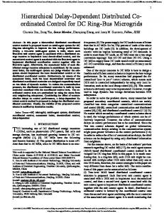
3. Automated Factory Shop Roor Consider the flexible manufaauring system (FMS)shown in Figure 1. sec Zhou et al (8). The FMS cakes rav input stock of WO rypes. machines them into desired shapes. and then a s e m b l a these two finished pars into a prod- One part sIam as a wxiaogular solid block and is milled and drilled on the CNC milling madune and ends as a gwmetrially shaped partwith a cyliodrisl bole in i t top. The other pan star6 as a cylindrical solid peg and is t u d by tbe CNC lathe into a complex cylindricdconical shaprd peg w b o s base fits into the bole of the f d e d block part n e robotic i"jon of the peg into the hole of the Mock is the assembly prThe family of prodfor this FMS comprbes various sizes and shapes of Mocks and assembled in this manner.
While this is the typical now to produce one output, the ruder is reminded that the sysrem wifl have concurrent work in prfor a number of product outputs. 4. S h c t m c d Modelling
Al. Storage Component Models
"be major components of the FMS,as illustrated in Figure 1. arc:
Peg Star8gr The peg store prwides the pcgr which can be removed (evcm r ) from the store. Namlly. the store is rauiaed (capacity C,) and a n b c refilled, provided therc is s p a , with new pep ( m n t U , adds A pegs). Let m, be the dam vviable storing the n u m b of in Ibe
1. "be CNC mill and drill machine,
2. "be CNC lathe, 3. T h e Ivliaubot robot. which is a shared ~ U I C Cused to load and unload the materials between the CNC milling machine and Conveyor 3, and between the CNC lathe and Conveyor 4, 4. The automated storage and retrieval system (ASRS).which is a buffer where pallets with raw materials and inmmdiate pars can be stored The ASRS structure is composed of 5'4 storage localions including 19 usable pallet-storage bins An elevator carries loaded pallets to and from the ASRS. 5. The automated material transfer system (AMTS) is a set of shared resourm which include four two-way conveyors (one pallet at a time) with presena censors at each end and a Gantry robot The AMIS is io charge of the m f c r of the materials between the different stations Universal pallets are used. i.e. they can hold all materials, parts and
The behaviour of the peg store is given by the inpuvoutput
s&.
equations
-
xl - ( r J m i : - l ] - u ) x3
(u;[nq:+q.]-
U)
-
x2-(';[~:-~]-u(q[q:+~j-u) y xl am, > 0D(xz a q 4D x 3 ) (3)
ODx3)
Y‘X,
x3-(Ui*u)
x, x2
x.4
- (13” -
- (U3
x2) U )
Y
- (1;
x3)
xg
- (p3
x4
x1
-x2~q2-x,) 111)
(rP
utllb
uz)
-
x2-(lb-x3)
x3-(IP-x4) X6
y1
(U*
- xI
xg)
x:3)
(04
x3
q1rf
x41u2
x31u1
xq-(u:-u)
x2
xs)
xs-(u:-u)
- -
U)
y-XI
-
--:. .I
%I41
(rl (U:
1 2‘ I
-:.I -- - - --
-*‘:I;],
Ir,I
xJ-;l
:.I.-
& I 4 )
y
U)
XI