Hierarchical Parsing and Recognition of Hand-Sketched Diagrams Levent Burak Kara Mechanical Engineering Department Carnegie Mellon University Pittsburgh, PA 15213
[email protected]
ABSTRACT
A long standing challenge in pen-based computer interaction is the ability to make sense of informal sketches. A main difficulty lies in reliably extracting and recognizing the intended set of visual objects from a continuous stream of pen strokes. Existing pen-based systems either avoid these issues altogether, thus resulting in the equivalent of a drawing program, or rely on algorithms that place unnatural constraints on the way the user draws. As one step toward alleviating these difficulties, we present an integrated sketch parsing and recognition approach designed to enable natural, fluid, sketch-based computer interaction. The techniques presented in this paper are oriented toward the domain of network diagrams. In the first step of our approach, the stream of pen strokes is examined to identify the arrows in the sketch. The identified arrows then anchor a spatial analysis which groups the uninterpreted strokes into distinct clusters, each representing a single object. Finally, a trainable shape recognizer, which is informed by the spatial analysis, is used to find the best interpretations of the clusters. Based on these concepts, we have built SimuSketch, a sketch-based interface for Matlab’s Simulink software package. An evaluation of SimuSketch has indicated that even novice users can effectively utilize our system to solve real engineering problems without having to know much about the underlying recognition techniques. Categories and Subject Descriptors: H.5.2 [User Interfaces]: Graphical User Interfaces (GUI), Interaction Styles; I.5.5 [Pattern Recognition]: Implementation, Interactive systems Additional Keywords and Phrases: Sketch understanding, pen computing, symbol recognition, visual parsing, sketch understanding, SimuSketch, Simulink INTRODUCTION
Pen-based computer interaction is becoming increasingly ubiquitous as evidenced by the growing interest in Tablet PC’s, electronic whiteboards and PDA’s. Many of these devices Permission to make digital or hard copies of all or part of this work for personal or classroom use is granted without fee provided that copies are not made or distributed for profit or commercial advantage and that copies bear this notice and the full citation on the first page. To copy otherwise, or republish, to post on servers or to redistribute to lists, requires prior specific permission and/or a fee. UIST ’04, October 24–27, 2004, Santa Fe, New Mexico, USA. c 2004 ACM 1-58113-957-8/04/0010. . . $5.00. Copyright °
Thomas F. Stahovich Mechanical Engineering Department University of California, Riverside Riverside, CA 92521
[email protected]
now come equipped with robust handwriting recognition, making them an attractive alternative to the keyboard and mouse for text entry. However, when it comes to graphical input, such as sketches and diagrams, such devices either leave the pen strokes uninterpreted, or offer only limited support in the form of stroke beautification or simple shape recognition. We believe that among the many issues that remain to be solved, there are two particular challenges that hinder the development of robust sketch understanding systems. The first is ink parsing, the task of grouping a user’s pen strokes into clusters representing intended symbols, without requiring the user to indicate when one symbol ends and the next one begins. This is a difficult problem as the strokes can be grouped in many different ways, and moreover, the number of stroke groups to consider increases exponentially with the number of strokes. The combinatorics thus clearly render approaches based on exhaustive search infeasible. To alleviate this difficulty, many of the current systems require the user to explicitly indicate the intended partitioning of the ink. This is often done by pressing a button on the stylus, or more commonly, by pausing between symbols [11, 25]. Alternatively, some systems avoid parsing by requiring each object to be drawn in a single pen stroke [20, 27, 17]. However, such constraints usually result in a less than natural drawing environment. The second issue is symbol recognition, the task of recognizing individual hand drawn figures such as geometric shapes, glyphs and symbols. While there has been significant recent progress in symbol recognition [27, 11, 6, 24], many recognizers are either hand-coded or require large sets of training data to reliably learn new symbol definitions. Such issues make it difficult to extend these systems to new domains with novel shapes and symbols. Additionally most symbol recognizers have been built as stand alone applications without addressing the issue of integration into high-level sketch understanding systems. In this paper, we address the issue of parsing and recognition of hand-drawn sketches in the domain of network diagrams. The types of sketches we consider can be broadly characterized as a set of symbols (nodes) connected by a set of arrows. The techniques we present are thus well-suited to a variety of diagrams such as signal flow diagrams, organizational charts and algorithmic flowcharts, and to various graphical models
Raw Sketch
Preliminary Recognition
Stroke Clustering
Symbol Candidates
Context
Symbol Recognition
Error Correction
Simulink Model
User
Figure 1: Recognition Architecture.
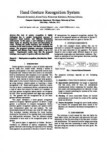
such as finite state machines, Markov models and Petri nets. Our approach is based on the hierarchical mark-group-recognize architecture shown in Figure 1. The first step focuses on identifying the arrows in the sketch. We refer to these arrows as “markers” because of two important properties: First, their geometric and kinematic characteristics enable them to be easily extracted from a continuous stream of strokes, and second, they serve as delimiters, which allow the remaining strokes to be efficiently clustered into distinct groups corresponding to individual symbols. The key here is that stroke clustering is driven exclusively by the arrows identified in the first step, without need for search. Next, informed by the result of the clustering algorithm, our approach employs contextual knowledge to generate a set of candidate interpretations for each of the stroke groups. The groups are then evaluated using a symbol recognizer to determine which of these interpretations is correct. The key advantage of our recognizer is that it can learn new symbol definitions from single prototype examples, thus allowing users to easily customize the system to their unique styles. The underlying imagebased pattern recognition techniques allow our recognizer to be applicable to multiple-stroke symbols without restricting the order in which the strokes are drawn. In cases of misrecognitions, the last step involves error correction where the user rectifies the mistakes. OVERVIEW
To provide a test bed for our work, we have created SimuSketch; a prototype sketch-based front-end to Matlab’s Simulink package (Figure 2). Simulink is used for analyzing feedback control systems and other similar dynamic systems. It has a typical drag and drop interface in which the user navigates through a nested symbol palette to find, select and drag the components, one at a time, onto an empty canvas. With SimuSketch, on the other hand, the user can construct functional Simulink models by simply sketching them on a computer screen. The sketch interface does not restrict the
Figure 2: (Top) SimuSketch, (Bottom) Automatically derived Simulink model.
order in which the symbols must be drawn nor the number of strokes used to draw them. Furthermore, it does not require the user to indicate when one symbol ends and the next begins. Likewise, the user need not complete one symbol before moving onto another, and thus the user may come back to a previous location to add more strokes at any time. The objects interpreted by SimuSketch are live from the moment they are recognized, thus enabling users to interact with them. For example users can edit the objects through dialog boxes or alter their sketch using traditional means such as selection and deletion. Once the user’s model is recognized, a simulation can be run and viewed directly in SimuSketch. At the end, users can save their work either in their original sketchy form or in a format compatible with Matlab, thus allowing users to resume their work either in the SimuSketch or the conventional Matlab environments. In the next section, we present a survey of previous research on sketch-based systems with an emphasis on parsing and recognition approaches. Further detail about interaction with SimuSketch and the underlying parsing and recognition techniques are detailed in the subsequent sections. RELATED WORK
Inspired by the advances in speech recognition, some systems facilitate parsing by requiring visual objects to be drawn with a predefined sequence of pen strokes [30, 33]. While useful at reducing computational complexity, the strong tem-
poral dependency in these methods forces the user to remember the correct order in which the strokes must be drawn. The nature of these approaches thus makes them more suitable to handwriting recognition rather than sketch recognition. Other approaches employ constrained search methods, where the idea is to generate a multitude of partial interpretations from the strokes, and later support or refute these interpretations based on new evidence [13]. Such approaches are often faced with the difficulty of non-optimal thresholds that either prematurely terminate a promising path, or retain a futile one for too long. Alvarado [3], on the other hand, proposed an extension to this idea in the form of Probabilistic Relational Models but has not yet presented formal evaluations. A number of techniques have been devised for parsing and recognition in visual scenes. Shilman et. al. [31] present a statistical visual language model for ink parsing. During training, a number of spatial relationships between objects are used to construct the object models. During recognition, the models are matched against the users’ strokes using a Bayesian framework. Their approach requires a description of a visual grammar, which is currently encoded manually. The trainable parser, on the other hand, requires a large number of training examples. Costagliola and Deufemia [7] present an approach based on LR parsing for the construction of visual language editors. They employ “extended positional grammars” to encode the attributes of the graphical objects and present a set of production/reduction rules for the grammar. Saund et. al. [29] present a system that uses Gestalt principles to determine the salient objects represented in a line drawing. Their work only concerns the grouping of the strokes and does not employ recognition to verify whether the identified groups are in fact the intended ones. Jacobs [16] describes a system to recognize objects with straightline perimeter representations. The system uses a number of heuristic rules to group edges that likely come from a single object, and then uses simple recognizers to identify the objects represented by the edges. However the rules rely on the presence of straight line segments and sharp corners, and thus are not well-suited to less structured patterns such as sketches. A number of systems that support sketch-based interaction have been developed in recent years. For user interface design, Landay and Myers [20] present an interactive sketching tool called SILK that allows designers to quickly sketch out a user interface and transform it into a fully operational system. Hong and Landay [14] describe a program called SATIN designed to support the creation of pen-based applications. Lin et al [22] describe a program called DENIM that helps web site designers in the early stages of the design process. All three programs use Rubine’s single-stroke gesture recognizer [27] as their main recognition tool and are thus not concerned with parsing. Alvarado and Davis [4] describe a system that can interpret and simulate a variety of simple, hand drawn mechanical systems. The system uses a number of heuristics to construct a recognition graph containing the likely interpretations of the sketch. The best interpretation is chosen using a scoring scheme that uses both contextual information and user feedback. In their approach, each time a new stroke is entered, the entire recognition tree is updated. By contrast,
we allow recognition to be controlled by the user. Also, their shape recognizers are sensitive to the results of segmentation (i.e., fitting line and arc segments to the raw ink) forcing the user to be cautious during sketching. Our approach does not rely on segmentation, thus allowing for more casual drawing styles. Matsakis [24] describes a system for recognizing handwritten mathematical expressions. The work presents an interesting idea based on minimum-spanning trees used for uncovering the spatial structure of the expressions. However the approach requires a large amount of training samples to learn new symbols, and each training sample needs to be drawn using the same number of strokes in the same direction and order. Similarly, recognition is sensitive to the number of strokes and order. Kurtoglu and Stahovich [18] describe a program that augments sketch understanding with qualitative physical reasoning to understand schematic sketches of physical devices. One key feature of their system is that it allows users to incorporate shapes from several different domains, instead of limiting them to one particular domain. In the field of shape recognition, some methods either rely on single stroke methods in which an entire symbol must be drawn in a single stroke [27, 17], or constant drawing order methods in which two similarly shaped patterns are considered different unless the pen strokes leading to those shapes follow the same sequence [26, 33]. Systems such as [5, 12] allow for multiple stroke symbols, however the recognizers are manually coded. While trainable, systems such as [11, 6, 24, 15] typically require a multitude of training examples. By contrast, we present a multiple stroke symbol recognizer that can learn definitions from single prototype examples. INTERACTION WITH SIMUSKETCH
SimuSketch is deployed on a 9 in x 12 in Wacom Cintiq digitizing tablet with a cordless stylus. The drawing surface of the tablet is an LCD display, which enables users to see virtual ink directly under the stylus. Data points are collected as time sequenced (x,y) coordinates sampled along the stylus’ trajectory. As shown in Figure 2-top, SimuSketch’s interface consists of a drawing region and a toolbar that contains buttons for commonly used commands. The user draws as he or she ordinarily would on paper. As the user is drawing, SimuSketch does not attempt to interpret the scene. Instead, it employs a recognize on demand (ROD) strategy in which the user taps the “Recognize” button in the toolbar whenever he wants the scene to be interpreted. This command invokes the sketch recognition engine which then parses the current sketch, recognizes the objects, and produces a Simulink model. As shown Figure 2-top, the program demonstrates its understanding by displaying a faint bounding box around each object, along with a text label indicating what the object is. Recognized arrows are delineated with small colored points at each of their two ends. The ROD strategy has a number of advantages over the systems that try to interpret the scene after each input stroke. First, as the users are not distracted by display of potentially premature interpretation results, they can focus exclusively on sketching. Second, as very little internal processing takes
dispatched and the object is removed from the visual scene. A typical manifestation of this gesture is a stroke through the selected object. Finally, if the entirety of the stroke is outside the blue region, all selected objects are de-selected and the stroke is added to the raw sketch. An alternative to deselection is a tap in the white space.
Figure 3: The user can interact with the system through sketch-based dialog boxes. The simulation results are displayed through conventional Simulink graphs.
place after each stroke, the program is better able to keep up with the user’s pace1 . Third, by delaying recognition in a user controlled manner, it allows the system to acquire more context that would help improve the recognition accuracy of earlier strokes. Note that ROD does not require the model to be entirely completed before it can be used. In fact, it encourages an iterative construction process in which the user draws a portion of the final model, asks SimuSketch to recognize it, tests the model, and continues with the rest of the model. Once the sketch is recognized, the user can run a simulation of it by pressing the “Simulate” button. This command simply hands the model over to Simulink (which runs in the background) for processing. The results of the simulation can be viewed directly in the sketch interface by double tapping on the Scope blocks. As shown in the right part of Figure 3, this brings up a window showing the simulation results. At any time, the user can add new objects to the model by simply sketching them. Object Manipulation: SimuSketch offers a number of gestures for different tasks. To select an object or an arrow, the user either taps on it or circles it with the stylus; the selected item is highlighted in a translucent blue color indicating its selection. The circular selection gesture is differentiated from a drawing stroke based on its end points and the region it encircles. If the distance between the stroke’s first and last points is less than 10% of the total stroke length (i.e., the stroke forms a nearly closed contour) and the stroke encircles one or more objects or arrows, the stroke is taken as a selection gesture. Once an object is selected, one of four things can happen depending on the subsequent input stroke. First, if the stroke is simply a quick tap in the blue region, a pop dialog message is dispatched, which brings up a dialog box pertinent to the selected object. Second, if the stroke is not a tap but its initial contact point is still within the blue region, a move message is dispatched and the selected object(s) is moved to the lift point of the stroke. Third, if both the contact and lift points of the stroke are outside the blue region but the midpoint is in the blue region, a delete message is 1 Systems that interpret the sketch after each stroke, such as [2], often force the user to pause for a short duration between the strokes.
Object Dialogs: For objects with variable parameters, selecting and tapping on the object brings up a dialog box for editing its parameters. The left part of Figure 3 shows an example. Interaction in these dialog boxes is also sketch-based in that users can cross out the old value with a delete gesture (a stroke through the number) and simply write in the new value. The program can recognize negative and/or decimal numbers using a digit recognizer we have developed. Views: Once the user’s sketch has been interpreted, the user has the option of viewing the model in its sketchy or cleaned up form. In the cleaned up view, the sketchy symbols are replaced by their iconic forms and the arrows are straightened out into line segments. Users can toggle between these two views by tapping the “Toggle view” button. Subjects in our user studies have indicated that the informality of the sketchy view gave a sense of freedom and creativity, while the cleaned up view gave a sense of completeness and definiteness. Despite these perceived differences, the cleaned up view is just as functional as the sketchy view in that it supports the same interaction mechanisms, including sketching, object selection, object manipulation and editing. SYSTEM DETAILS
In the following sections, we detail each of the steps of our multi-level parsing and recognition approach outlined in Figure 1. Preliminary Recognition
One key to successful sketch understanding lies in the ability to establish the ground truths about the sketch early on, before costly mistakes take place. Based on this idea, we introduce the concept of “marker symbols,” symbols that are easy to recognize and that can guide the interpretation of the remainder of the sketch. In the domain of network diagrams, arrows fulfill this purpose. This approach is similar in spirit to the construction of “islands of certainty” in the Hearsay-II speech understanding system [9]. There are several reasons why arrows are useful marker symbols. First, they occur relatively frequently in network diagrams, thus providing good resolution for separating the other symbols. Second, arrows have unique geometric and kinematic (e.g., pen speed) features that allow them to be reliably extracted from the input stream. Third, as explained later, arrows help guide the interpretation of the other symbols in the sketch by narrowing down the set of possible interpretations. SimuSketch thus begins by recognizing the arrows. Our observational tests on a small set of users during the design stages of our system indicated that, despite some exceptions, arrows were usually drawn as either a single pen stroke or two consecutive strokes, one for the shaft and one for the head. We thus developed two types of arrow recognizers to account for these two styles. To simplify our analysis, we require that both types of arrows be drawn from tail to head.
B
(a)
R 0.7
A
C
(a)
D
0.6 0.5
(b)
Speed
0.4 0.3
R
0.2 0.1
B
A
C
D
(b)
0 1
7
13
19
25
31
37
43
49
55
61
67
73
79
85
91
97 103 109 115 121 127 133 139 145
-0.1 -0.2 Tim e
Figure 4: Arrow recognition. (a) A one-stroke arrow with the key points labeled. (b) Speed profile. Key points are speed minima.
(c)
(a) (d)
(b) Figure 5: Examples of (a) arrows and (b) arrow heads, that are correctly recognized.
Here we describe only the single-stroke arrow recognizer, as the two-stroke recognizer is a minor extension of it. Arrow recognition is based on the identification of five key points, labeled A, B, C, D and R in Figure 4a. Points A, B and C correspond to the sharp corners on the arrowhead. The distinguishing characteristic of these points is that they all correspond to pen speed minima, as can be seen in the pen speed profile in Figure 4b. These points are thus identified by locating the last three global minima in the speed profile, excluding the end point, which is labeled point D. Finally, R is a “reference” point on the arrow shaft and is obtained by moving a small distance backwards from point A. Once these points are determined, a series of geometric tests is performed to determine whether or not the stroke really is d BCD, d RAB d and an arrow. We require the four angles ABC, ◦ d to all be less than 90 , and the length of line segments RAD BC and DC to be less than 20% of the total stroke length. These geometric tests were designed empirically by collecting a corpus of positive and negative examples of arrows from several users, and experimenting with different levels of specificity and thresholds until the best classification performance was obtained. With the resulting recognizer, a variety of arrow shapes with different arrowhead styles can be recognized as shown in Figure 5. Stroke Clustering
Once the arrows have been recognized, the next step is to group the remaining strokes into different clusters, representing different symbols. The key idea behind stroke clustering is that strokes are deemed to belong to the same symbol only when they are spatially proximate. The challenge is reliably determining when two pen strokes should be con-
Figure 6: Illustration of the cluster analysis. (a) Each stroke is assigned to the nearest arrowhead or tail. (b) Strokes assigned to the same arrow are grouped into clusters. (c) Clusters with overlapping bounding boxes are merged. (d) Arrows that did not receive any strokes are attached to the nearest cluster.
sidered close together. Here, we rely on the arrows to help make this determination. In network diagrams, each arrow typically connects a source object at its tail to a target object at its head. Hence, different clusters can be identified by grouping together all the strokes that are near the end of a given arrow. In effect, two strokes are considered spatially proximate if the nearest arrow is the same for each. Based on this observation, we developed the following procedure for identifying symbol clusters: Step-1 Assign each non-arrow stroke to the nearest arrow: Stroke clustering begins by assigning each non-arrow stroke to the nearest arrow (Figure 6a). The distance between a stroke and an arrow is defined to be the Euclidean distance between the median point of the stroke and either the head or tail of the arrow, whichever is closer. The head is taken to be the apex, which is shown as point C in Figure 4. Step-2 Combine strokes into clusters: Strokes assigned to the same arrow end in Step-1 are grouped to form a stroke cluster. These clusters will form the basis of the symbols. Figure 6b shows the results of this step. Step-3 Merge overlapping clusters: Next, clusters with partially or fully overlapping bounding boxes are merged. The bounding box of a cluster is the minimum sized rectangle, aligned with the coordinate axes, that fully encloses the constituent strokes. As shown in Figure 6c, this process combines strokes that are part of the same symbol but which were initially assigned to different arrows in Step-1. If bounding
Sine Wave
Sum
Switch
Figure 7: Examples of symbol templates.
boxes of different symbols overlap, this process could erroneously merge the symbols. However, in our experience, we have found that users rarely draw in such a way that this happens. Thus, at the completion of this step, each cluster is assumed to be a distinct symbol. Step-4 Connect empty arrowhead/tails to the nearest cluster: Step-1 guarantees that each non-arrow stroke is attached to the nearest arrow end. However, some of the arrow ends might remain devoid of any strokes. In this step, empty arrow ends are linked to the nearest stroke cluster (Figure 6d). This step helps to ensure the intended connectivity of the diagram by ensuring that each arrow has a cluster at its tail and head. Generating Symbol Candidates
After identifying the stroke clusters, the next step is to recognize the symbols they represent. Our approach combines contextual knowledge with shape recognition to achieve accuracy and efficiency. In particular, we examine the number of input and output arrows associated with each stroke cluster to help constrain its possible interpretations. For example, function generators such as the Sine Wave can have only output terminals, and therefore, must have only outgoing arrows. Likewise, certain symbols can have only input terminals, such as the Scope block, or may have an arbitrary number of input and output terminals such as the Sum block. By examining the number of input and output arrows for a given cluster, SimuSketch identifies a set of candidate symbols for the cluster. This reduces the amount of work the subsequent shape recognizer must do and additionally helps increase accuracy by reducing the possibilities for confusion. For example, while the Sum block and the Clock look quite similar (the two circular symbols in Figure 6), context dictates that a Sum block must have at least two incoming arrows while the Clock must have none. With this additional knowledge, the shape recognizer would never consider the Sum block and the Clock as two competing candidates during shape recognition. Symbol Recognition
We have developed a novel image-based symbol recognizer that can recognize shapes independent of their position, size and orientation.2 However, it is sensitive to non-uniform scaling, and thus we can distinguish between, say, a square and a rectangle. A distinguishing feature of this recognizer is that it is used for recognizing both the Simulink objects, and the digits in the objects’ dialog boxes. 2 Our recognizer uses a polar coordinate representation to efficiently account for changes in orientation, but that is beyond the current scope.
Input symbols are internally described as 24x24 quantized bitmap images which we call “templates”. Figure 7 shows example symbol templates. This representation has a number of desirable characteristics. First, segmentation – the process of decomposing the symbol into constituent primitives such as lines and curves – is eliminated entirely. Second, the representation is well suited for recognizing “sketchy” symbols such as those with heavy overtracing, missing or extra segments, and different line styles (solid, dashed, etc.). Lastly, this recognizer puts no restrictions on the number of strokes, or the order in which the strokes are drawn. Unlike many traditional methods, our shape recognizer requires only a single prototype example to learn a new symbol definition. Using the “Train New” button in the interface, the user can create a new symbol definition by simply drawing a shape and assigning a name to it. With this approach, users can seamlessly train new symbols or overwrite existing ones on the fly, without having to depart the main application. This feature makes it easy for users to extend and customize their symbol libraries.3 Our recognizer uses an ensemble of four different classifiers to evaluate the match between an unknown symbol and a candidate definition symbol. The classifiers we use are extensions of the following methods: (1) Hausdorff distance [28], (2) Modified Hausdorff distance [8], (3) Tanimoto coefficient [10] and (4) Yule coefficient [32]. The Hausdorff methods reveal the dissimilarity between two templates by measuring the distance between the maximally distant pixels in the two point sets. The Tanimoto coefficient on the other hand reveals the similarity between two templates by measuring the amount of overlapping black pixels. The Yule coefficient is also a similarity measure except it considers the matching white pixels in addition to the matching black pixels. The motivation for using a multiple classifier scheme lies in the pragmatic evidence that, although individual classifiers may not perform perfectly, they usually rank the true definition highly, and tend to misclassify differently [1]. Hence, by advocating definitions ranked highly by all four classifiers, while suppressing those that are not, we can determine the true class more reliably. During recognition, each classifier outputs a list of symbol definitions ranked according to their similarity to the unknown. Results of the individual classifiers are then synthesized by first transforming the similarity measures into dissimilarity measures, then normalizing the classifiers’ output into a unified scale (to make them compatible), and finally combining the modified outputs of the classifiers. The definition symbol with the best combined score is chosen as the symbol’s interpretation. Error Correction
Our system provides several means to correct recognition errors when they occur. Our techniques have strong parallels with the mediation techniques presented in [23]. When an 3 Currently SimuSketch has the operational knowledge of 16 Simulink objects. However, the extension to other Simulink objects is straightforward, requiring only code for linking the objects in SimuSketch to those in Simulink.
object is misrecognized, the user can repeat the object by selecting, deleting and redrawing it. A more direct way is by choosing the correct interpretation from a choice list, which is revealed by bringing the stylus near the misrecognized object and pressing one of the buttons on its side. This list contains only the candidate symbols previously determined using contextual information, and is ranked according to the results of the shape recognizer. Hence, the list is typically short with the correct interpretation usually occurring near the top. Finally, if an arrow goes undetected, and hence becomes part of an object, the user can dictate the correct interpretation by drawing a small circle on or near the stroke. This gesture, which we call the ‘o’ gesture, explicitly forces the stroke in question to be an arrow. The ‘o’ gesture is distinguished from a regular drawing stroke based on its absolute size and its two end points. If the gesture fits in a 30 x 30 square on a 1024 x 768 screen, and the stroke forms a closed contour (similar to a selection gesture) without encircling any object, the stroke is interpreted as an ‘o’ gesture. Once a misrecognized arrow is corrected, SimuSketch automatically rectifies the portion of the sketch that was affected by the missed arrow. USER STUDIES
We conducted two user studies to evaluate our system. The first study focused on the performance of our symbol recognizer and was conducted with a simple interface designed for this study. The second investigated users’ reactions to SimuSketch as a pen-based interaction system, and the evaluation was more observational compared to the first study. Evaluation of the Symbol Recognizer: Our evaluation of the symbol recognizer consisted of two experiments. In the first experiment, we used a set of 20 graphic symbols shown in Figure 8. Five users participated in this experiment, each of whom was asked to provide three sets of the symbols using the digitizing tablet. In the second experiment, we used digit recognition as our test bed. Nine users participated in the second study and each was asked to provide six sets of digits from “0” to “9”. Both experiments were conducted in a user-dependent setting in which the recognizer was evaluated using the user’s own training symbols. The last set from each user was used for training while the previous ones were used for testing. Each session involved only data collection; the data was processed at a later time. This approach was chosen to prevent users from adjusting their writing style based on our program’s output. When the top-one classification performance is considered, the recognition rate from the graphic symbol study was 87%. However when top-two classification performance is considered, i.e., the rate at which the correct class is either the highest or second highest ranked class, the accuracy was 97.5%. We consider the top-two classification performance to be of considerable importance, as it provides a measure of how frequently the correct class will appear in the list of alternatives suggested by our program during error correction. For the digit recognition study, the top-one accuracy was 93.8% and the top-two accuracy was 98.0%. State-of-theart hand-drawn digit recognition systems achieve recognition rates above 96-97% in user-independent settings [19, 21], however, these systems usually work from scanned images
Figure 8: Symbols used in the graphic symbol recognition experiment.
which adds another level of complexity to their task. We achieve about 94% accuracy in a setting where the recognition is user-dependent and the input data is not affected by poor image quality. Nevertheless, we consider our approach to be quite attractive given that it works from a single training example. To have a point of comparison, LeCun’s neural network recognizer [21] for handwritten digits, one of the best in its class, uses a total of 60,000 digits for training purposes. As one would expect, if the problem is to recognize digits only, it is better to use a dedicated digit recognizer. However, if the problem involves user defined symbols, such as those shown in Figure 8, our approach has distinct advantages. Evaluation of SimuSketch: The focus of this study was to assess the performance of SimuSketch. Among the various aspects that we investigated, we were particularly interested in SimuSketch’s ease of use, its parsing and recognition accuracy, users’ adaptability to the system, their success at recovering from recognition errors, and their short and long term view of SimuSketch as a practical front-end to Simulink. A total of 14 graduate and undergraduate students – 12 engineering and 2 computer science majors – participated in the studies. Nearly half of the users either regularly used Simulink or had previously used it once or twice, while the other half had never used Simulink before. 10 users had no prior experience with the digitizing tablet or the stylus, while 4 users had once used the hardware in a previous study. However, none of the users had previously used SimuSketch, nor had seen it in use by others. Each session lasted approximately 30 to 40 minutes. For those who were not familiar with Simulink, we first described what Simulink is and gave a brief demonstration on its interface. Next, we introduced SimuSketch. Using simple examples, we demonstrated the means for creating a sketch, selecting, deleting and moving objects, editing object properties, correcting recognition errors, running simulations, training new symbols and switching between views. During this period, we elaborated on SimuSketch’s arrow recognizer as our experience with the first few users had indicated the arrow recognition to be fragile at times. Particularly, we told the users that only single or two stroke arrows were permitted and both types had to be drawn from a source object toward a target object. Other than the recognition of arrows, no fur-
taking too long for them to finish the task. The users’ main remark about SimuSketch was that it was intuitive and fast to use, and easy to learn. They particularly liked the idea of simply drawing the objects without having to navigate through an object library to find them. Most users found the interaction mechanisms to be “natural” and “familiar.” Many highlighted the ability to quickly train a custom set of symbols as an outstanding attribute, although they did not make use of it. The user studies enabled us to evaluate the individual accuracies of our arrow recognizer, parsing algorithm, and symbol recognizer. In its current implementation, our program saves only the user’s final sketch, and any objects that are deleted during a drawing session are lost. Our initial accuracy calculations thus do not reflect errors that users repaired by deleting and redrawing objects. This does not produce a significant error in our accuracy calculations, however, because users in the study rarely repaired interpretation errors in this way. In the results presented below, we include estimates of the accuracy that would have been obtained if all interpretation errors had been considered. Figure 9: Test problems employed in the user studies.
ther explanation was given regarding the underlying parsing and recognition algorithms. At the end of this introduction, a brief warm up period of approximately 5 minutes was given to let the users become familiar with the hardware and SimuSketch’s interface. The main test involved the two Simulink models shown in Figure 9. Users were asked to use SimuSketch to construct these models, run a simulation of each, and view the results with minimal help from us. The first model involved changing the parameters of several objects through their dialog boxes while in the second model the default values were accepted. Because the users were not involved in the training of the object shapes, none of them knew what the trained shapes looked like. Although users were given the option to train their own set of symbols before starting, none of them chose to do so. Hence, we provided a sketched version of each of the two models as a quick reference. Both the original models and the sample sketches were presented on paper. Similarly, all users decided to use the pre-trained digit recognizer rather than training their own set of digits. However, in this case we did not provide sample figures of the trained digits. Although no time constraints were set, we encouraged users to complete their tasks in a total of 20 minutes. Observations, Evaluations and Discussions One consistent pattern among the users was that their encounter with SimuSketch began with great excitement as observed from their reactions during the demo session. This was followed by a period of frustration at the beginning of the warm up period, and finally reached a favorable equilibrium toward the end of the warm up period and during the actual testing. At the end, all users completed the first task successfully, while all but four users completed the second task. In the case of the four users, either the program crashed unexpectedly and they did not have time to redo it, or it was
The study has shown the main strength of SimuSketch to be its parsing algorithm. In cases where the arrows were all correctly recognized, or the misrecognized ones were corrected by the user, the parsing algorithm had an accuracy above 95%. In the few cases it failed, two distinct symbols were drawn too close to each other and thus their strokes were grouped into a single cluster. In cases where all stroke clusters were correctly identified, the symbol recognition accuracy was between 85 and 90%. Note that while this result is obtained in a user-independent setting (i.e., the training and test symbols belong to different individuals), it is similar to the result of the user-dependent study explained in the previous section. We believe that SimuSketch’s ability to maintain the same level of accuracy in a more difficult setting can be attributed to its use of contextual knowledge for narrowing down the set of interpretations of a symbol prior to recognition. Nevertheless, when errors occurred, they were mostly due to: (1) the confusion between similarly shaped objects, or (2) the recognizer’s sensitivity to non-uniform scaling. Figure 10 shows examples of these issues. However, contrary to our expectation, users did not seem to mind such occasional errors, mainly because they found the means for recovery – either by deleting and redrawing, or by selecting the right interpretation from the list of alternatives – to be intuitive and undemanding. In the latter case, the correct interpretation was always in the list of alternatives suggested by SimuSketch. The main complaint about SimuSketch centered around the arrow recognizer being too restrictive. Although several users quickly became adept at drawing arrows during the warm up period, most users continued having difficulty during the main test session. As we expected, the majority of the errors thus occurred due to the misrecognized arrows. For the most successful users, the arrow recognition accuracy was above 90%. However, when considering all users, the average accuracy for arrow recognition was between 65 and 70%. These results indicate that our arrow recognizer must be further improved to accommodate a wider variety of
(a) Random
Chirp
Coul. & Visc. Friction
Sign
(b) Definition of Transfer Function
One user’s Transfer Function
Figure 10: (a) Pairs of most frequently confused objects. (b) A misrecognition due to non-uniform scaling. (Left) Definition symbol, (Right) One user’s misrecognized symbol.
styles. One approach in this direction would be to replace the hard-coded thresholds of the geometric constraints with thresholds that are tunable to individual users. Besides the issue with arrows, some users had difficulty tapping the stylus to select an object or to bring up a dialog box. Usually, faulty taps were either too gentle, in which case the program did not receive a tap message, or persisted too long on the tablet, in which case the tap was interpreted as a drawing stroke. Another observed difficulty was with the digit recognition in the dialog boxes. While our pre-trained digit recognizer had acceptable performance for certain users, it could not accommodate the vastly dissimilar digit styles that it was not trained for. In cases where the numbers were misrecognized, we asked the users to re-enter them until they got it right. If each user had trained his or her set of digits, we expect that the accuracy would have been similar to the results presented in the previous section. To obtain the users’ evaluation of SimuSketch’s performance, we asked each user to complete a questionnaire at the end of the session. The results shown in Table 1 indicate that, while there are a number of usability issues that must be addressed, most users viewed SimuSketch as a promising alternative to Simulink. Because SimuSketch is still at an early stage, we have deliberately avoided a head-to-head comparison between SimuSketch and Simulink in our user studies. Nevertheless, as a subjective test of how an individual who is proficient in both environments would perform, one of the authors used the two programs to construct and simulate a variation of the second model shown in Figure 9. The test involved creating the model, changing the default properties of several objects, and viewing the simulation results. While the task took 241 seconds to complete in Simulink, it took only 183 seconds in SimuSketch. Although simplistic, we believe this experiment helps reveal the latent value of SimuSketch as a practical tool. CONCLUSIONS
We have presented a multi-level parsing and recognition approach designed to enable natural sketch-based computer interaction. This approach allows users to continuously sketch without indicating when one symbol ends and a new one begins. Additionally, it does not restrict the number of strokes,
As I was using SimuSketch , I was able to adapt to it easily The software was fast enough to keep up with my pace Most of the time, SimuSketch interpreted my sketch the way I intended Most of the time, SimuSketch behaved expectedly and when it did not, I felt I was in control to fix it The visual feedback on the interpretation results was adequate and unobtrusive The editing operations (select, move, delete deselect) were intuitive and easy to use I was comfortable using objects’ dialog boxes to enter numeric values Currently, the overall performance of SimuSketch is Assuming that SimuSketch was significantly more robust I would use it in my projects Overall, my rating of SimuSketch is
Score 8.2 7.8 7.4 8.2 9.1 8.3 7.7 7.6 9.4 8.7
Table 1: Average scores obtained from user questionnaire. Scale: 1-10, 10 being excellent.
or the order in which they must be drawn. Our approach is based on a mark-group-recognize architecture. In the first step, our program identifies the arrows in the sketch, which serve as useful markers that separate the uninterpreted strokes into distinct clusters. After the symbol clusters are identified, an image-based symbol recognizer, which is informed by clustering and domain specific knowledge, is used to find the best interpretations of the strokes. One advantage of this recognizer over traditional ones is that it can learn new definitions from single prototype examples. The recognizer is versatile in that we use it both for graphical symbol recognition and digit recognition. We have demonstrated our approach with SimuSketch, a sketch-based interface for Simulink. User studies have indicated that we have sound algorithms for parsing and symbol recognition, and useful means for error recovery. However, our current arrow recognizer should be improved to enhance the user’s experience with SimuSketch. Overall, most users had highly favorable opinions of our prototype system, and found it easy and straightforward to use. While useful for the practicing engineer, SimuSketch is likely to have distinct advantages in engineering education. By its nature, SimuSketch is ideally suited for electronic whiteboard applications and thus can be readily integrated into the classroom environment. In the near future, we plan to explore this possibility with pilot studies. Finally, although the techniques presented in this paper are tailored toward the domain of network diagrams, our preliminary studies suggest that our mark-group-recognize approach may be applicable to other domains as well. We are currently working to apply this approach to several other domains including electrical circuits and mechanical systems.
References
1. Fevzi Alimoglu and Ethem Alpaydin. Combining multiple representations for pen-based handwritten digit recognition. ELEKTRIK: Turkish Journal of Electrical Engineering and Computer Sciences, 9(1):1–12, 2001. 2. Christine Alvarado. A Natural Sketching Environment: Bringing the Computer into Early Stages of Mechanical Design. Master thesis, MIT, 2000. 3. Christine Alvarado. Dynamically constructed bayesian networks for sketch understanding. Technical report, MIT Project Oxygen Student Workshop Abstracts, 2003. 4. Christine Alvarado and Randall Davis. Resolving ambiguities to create a natural sketch based interface. In IJCAI-2001, 2001. 5. Ajay Apte, Van Vo, and Takayuki Dan Kimura. Recognizing multistroke geometric shapes: An experimental evaluation. In UIST 93, pages 121–128, 1993. 6. Chris Calhoun, Thomas F Stahovich, Tolga Kurtoglu, and Levent Burak Kara. Recognizing multi-stroke symbols. In AAAI Spring Symposium on Sketch Understanding, pages 15–23, 2002. 7. Gennaro Costagliola and Vincenzo Deufemia. Visual language editors based on lr parsing techniques. In 8th International Workshop on Parsing Technologies (IWPT’03), Nancy, France, 2003. 8. Marie-Pierre Dubuisson and Anil K Jain. A modified hausdorff distance for object matching. In 12th International Conference on Pattern Recognition, pages 566– 568, Jerusalem, Israel, 1994. 9. Lee D Erman, Frederick Hayes-Roth, Victor R Lesser, and D Raj Reddy. The hearsay-ii speech understanding system: Integrating knowldge to resolve uncertainty. Computing Surveys, 12(2):213–253, 1980. 10. Michael Fligner, Joseph Verducci, Jeff Bjoraker, and Paul Blower. A new association coefficient for molecular dissimilarity. In The Second Joint Sheffield Conference on Chemoinformatics, Sheffield, England, 2001. 11. Manueal J Fonseca, Cesar Pimentel, and Jaoquim A Jorge. Cali-an online scribble recognizer for calligraphic interfaces. In AAAI Spring Symposium on Sketch Understanding, pages 51–58, 2002. 12. Manuel J Fonseca and Joaquim A Jorge. Using fuzzy logic to recognize geometric shapes interactively. In Proceedings of the 9th Int. Conference on Fuzzy Systems (FUZZ-IEEE 2000). San Antonio, USA, 2000. 13. W Eric L Grimson. The combinatorics of heuristic search termination for object recognition in cluttered environments. IEEE PAMI, 13(9):920–935, 1991. 14. Jason I Hong and James A Landay. Satin: A toolkit for informal ink-based applications. In ACM UIST 2000 User Interfaces and Software Technology, pages 63–72, San Diego, CA, 2000. 15. Heloise Hse and A. Richard Newton. Sketched symbol recognition using zernike moments. Technical report, EECS, University of California, 2003. 16. David W Jacobs. The use of grouping in visual object recognition. Technical Report Technical Report 1023, MIT AI Lab, 1988. 17. T D Kimura, A Apte, and S Sengupta. A graphic diagram editor for pen computers. Software Concepts and
Tools, pages 82–95, 1994. 18. Tolga Kurtoglu and Thomas F Stahovich. Interpreting schematic sketches using physical reasoning. In AAAI Spring Symposium on Sketch Understanding, pages 78– 85, 2002. 19. Ernst Kussul and Tatyana Baidyk. Improved method of handwritten digit recognition tested on mnist database. In 15th International Conference on Vision Interface, Calgary, Canada, 2002. 20. James A Landay and Brad A Myers. Sketching interfaces: Toward more human interface design. IEEE Computer, 34(3):56–64, 2001. 21. Y LeCun, L D Jackel, L Bottou, A Brunot, C Cortes, J S Denker, H Drucker, I Guyon, U A Muller, E Sackinger, P Simard, and V Vapnik. Comparison of learning algorithms for handwritten digit recognition. In International Conference on Artificial Neural Networks, pages 53–60, Paris, 1995. 22. James Lin, Mark W. Newman, Jason I. Hong, and James A. Landay. Denim: Finding a tighter fit between tools and practice for web site design. In CHI Letters: Human Factors in Computing Systems, pages 510–517. ACM Press, 2000. 23. Jennifer Mankoff, Gregory D. Abowd, and Scott E Hudson. Oops: a toolkit supporting mediation techniques for resolving ambiguity in recognition-based interfaces. Computers and Graphics, 24(6):819–834, 2000. 24. Nicholas E Matsakis. Recognition of Handwritten Mathematical Expressions. Master thesis, MIT, 1999. 25. Shankar Narayanaswamy. Pen and Speech Recognition in the User Interface for Mobile Multimedia Terminals. Ph.d. thesis, University of California at Berkeley, 1996. 26. Omer Faruk Ozer, Oguz Ozun, C Oncel Tuzel, Volkan Atalay, and A Enis Cetin. Vision-based single-stroke character recognition for wearable computing. IEEE Intelligent Systems and Applications, 16(3):33–37, 2001. 27. Dean Rubine. Specifying gestures by example. Computer Graphics, 25:329–337, 1991. 28. W J Rucklidge. Efficient Visual Recognition Using the Hausdorff Distance. Number 1173 Lecture Notes in computer Science,. Springer-Verlag, Berlin, 1996. 29. Eric Saund, James Mahoney, David Fleet, Dan Larner, and Edward Lank. Perceptual organisation as a foundation for intelligent sketch editing. In AAAI Spring Symposium on Sketch Understanding, pages 118–125, 2002. 30. Tevfik Metin Sezgin. Generic and HMM based approaches to freehand sketch recognition. Technical report, MIT Project Oxygen Student Workshop Abstracts, 2003. 31. Michael Shilman, Hanna Pasula, Stuart Russell, and Richard Newton. Statistical visual language models for ink parsing. In AAAI Spring Symposium on Sketch Understanding, pages 126–132, 2002. 32. Jack D Tubbs. A note on binary template matching. Pattern Recognition, 22(4):359–365, 1989. 33. H Yasuda, K Takahashi, and T Matsumoto. A discrete HMM for online handwriting recognition. International Journal of Pattern Recognition and Articial Intelligence, 14(5):675–688, 2000.