May 25, 2013 - This work is funded by Huawei Technologies. proposed to find a stationary point of the weighted sum-rate maximization problem for multi-cell ...
Hierarchical Radio Resource Optimization for Heterogeneous Networks with Enhanced Inter-cell Interference Coordination (eICIC)
arXiv:1305.5884v1 [cs.IT] 25 May 2013
An Liu1 , Member IEEE, Vincent K. N. Lau1 , Fellow IEEE, Liangzhong Ruan1 , Junting Chen1 , Member IEEE, and Dengkun Xiao2 1 Department of Electronic and Computer Engineering, Hong Kong University of Science and Technology 2 Huawei Technologies CO., LTD.
Abstract—Interference is a major performance bottleneck in Heterogeneous Network (HetNet) due to its multi-tier topological structure. We propose almost blank resource block (ABRB) for interference control in HetNet. When an ABRB is scheduled in a macro BS, a resource block (RB) with blank payload is transmitted and this eliminates the interference from this macro BS to the pico BSs. We study a two timescale hierarchical radio resource management (RRM) scheme for HetNet with dynamic ABRB control. The long term controls, such as dynamic ABRB, are adaptive to the large scale fading at a RRM server for co-Tier and cross-Tier interference control. The short term control (user scheduling) is adaptive to the local channel state information within each BS to exploit the multi-user diversity. The two timescale optimization problem is challenging due to the exponentially large solution space. We exploit the sparsity in the interference graph of the HetNet topology and derive structural properties for the optimal ABRB control. Based on that, we propose a two timescale alternative optimization solution for the user scheduling and ABRB control. The solution has low complexity and is asymptotically optimal at high SNR. Simulations show that the proposed solution has significant gain over various baselines. Index Terms—Heterogeneous Network, Dynamic ABRB Control, Two Timescale RRM
I. I NTRODUCTION As HetNet provides flexible and efficient topology to boost spectral efficiency, it has recently aroused immense interest in both academia and industry. As illustrated in Fig. 1, a HetNet consists of a diverse set of regular macro base stations (BS) overlaid with low power pico BSs. Since this overlaid structure may lead to severe interference problem, it is extremely critical to control interference via RRM in HetNet. There has been much research conducted on RRM optimization for traditional cellular networks. In [1], [2], the authors considered power and user scheduling in single-carrier cellular networks. In [3], [4], the game theoretical approaches are proposed for distributed resource allocation. In [5], the authors proposed a dynamic fractional frequency reuse scheme to combat the inter-sector interference under a game-based optimization by each sector. The coordinated multipoint transmission (CoMP) [6] is another important technique to handle the inter-cell interference. For example, in [7], the authors exploited the uplinkdownlink duality to do joint optimization of power allocation and beamforming vectors. In [8], a WMMSE algorithm is This work is funded by Huawei Technologies.
proposed to find a stationary point of the weighted sum-rate maximization problem for multi-cell downlink systems. While the above algorithms achieve comparably good performance, they require global channel state information (CSI) for centralized implementation [7] or over-the-air iterations and global message passing for distributed implementation [8]. It is quite controversial whether CoMP is effective or not in LTE systems due to large signaling overhead, signaling latency, inaccurate CSIT, and the complexity of the algorithm. On the other hand, solutions for traditional cellular networks cannot be applied directly to HetNet due to the unique difference in HetNet topology. First, the inter-cell interference in HetNet is more complicated, e.g., there is co-tier interference among the pico BSs and among the macro BSs as well as the cross-tier interference between the macro and pico BSs. Furthermore, due to load balancing, some of the mobiles in HetNet may be assigned to a pico BS which is not the strongest BS [9] and the mobiles in the pico cell may suffer from strong interference from the macro BSs. To solve these problems, some eICIC techniques, such as the ABS control [9], have been proposed in LTE and LTE-A [10]. In [11], the authors analyzed the performance for ABS in HetNet under different cell range extension (RE) biases. However, they focused on numerical analysis for the existing heuristic eICIC schemes, which are the baselines of this paper. In [12], the authors proposed an algorithm for victim pico user partition and optimal synchronous ABS rate selection. However, they used a universal ABS rate for the whole network, and as a result, their scheme could not adapt to dynamic network loading for different macro cells. In this paper, we focus on the resource optimization in the downlink of a HetNet without CoMP1 . We consider dynamic ABRB for interference control and dynamic user scheduling to exploit multi-user diversity. The ABRB is similar to the ABS but it is scheduled over both time and frequency domain. Unlike [12], we do not restrict the ABRB rate to be the same for all macro BSs and thus a better performance can be achieved. However, this also causes several new technical challenges as elaborated below. 1 While there are a lot of works using multi-antenna techniques (CoMP) to mitigate interference in HetNet [7], [13], such approaches require accurate knowledge of at least the cross-link CSIT at each macro and pico BS, which is not realistic in practice. As a result, the LTE-A working groups are actively studying eICIC techniques such as ABS for interference control of HetNet.
2
Exponential Complexity for Dynamic ABRB: Optimization of ABRB patterns is challenging due to the combinatorial nature and exponentially large solution space. For example, in a HetNet with N0 macro BSs, there are 2N0 different ABRB pattern combinations. Hence, brute force solutions are highly undesirable. • Complex Interactions between dynamic user scheduling and dynamic ABRB: There is complex coupling between the dynamic user scheduling and ABRB control. For instance, the ABRB pattern will affect the user sets eligible for user scheduling. Furthermore, the optimization objective of ABRB control depends on user scheduling policy and there is no closed form characterization. • Challenges in RRM Architecture: Most existing solutions for resource optimization of HetNet requires global knowledge of CSI and centralized implementations. Yet, such designs are not scalable for large networks and they are not robust with respect to (w.r.t.) latency in backhaul. To address the above challenges, we propose a two timescale control structure where the long term controls, such as dynamic ABRB, are adaptive to the large scale fading. On the other hand, the short term control, such as the user scheduling, is adaptive to the local CSI within a pico/macro BS. Such a multi-timescale structure allows Hierarchical RRM design, where the long term control decisions can be implemented on a RRM server for inter-cell interference coordination. The short-term control decisions can be done locally at each BS with only local CSI. Such design has the advantages of low signaling overhead, good scalability, and robustness w.r.t. latency of backhaul signaling. While there are previous works on two timescale RRM [11], [12], those approaches are heuristic (i.e. the RRM algorithms are not coming from a single optimization problem). Our contribution in this paper is a formal study of two timescale RRM algorithms for HetNet based on optimization theory. To overcome the exponential complexity for ABRB control, we exploit the sparsity in the interference graph of the HetNet topology and derive structural properties for the optimal ABRB control. Based on that, we propose a two timescale alternative optimization solution for user scheduling and ABRB control. The algorithm has low complexity and is asymptotically optimal at high SNR. Simulations show that the proposed solution has significant performance gain over various baselines. Notations: Let 1 (·) denote the indication function such that 1 (E) = 1 if the event E is true and 1 (E) = 0 otherwise. For a set S, |S| denotes the cardinality of S. •
II. S YSTEM M ODEL AND H IERARCHICAL R ESOURCE C ONTROL P OLICIES A. HetNet Topology and Physical Layer Model Consider the downlink of a two-tier HetNet as illustrated in Fig. 1. There are N0 macro BSs, N − N0 pico BSs, and K users, sharing M OFDM subbands. Denote the set of the macro BSs as BMA = {1, ..., N0 }, and denote the set of the pico BSs as BPI = {N0 + 1, ..., N }. The HetNet topology (i.e., the network connectivity and CSI of each link) is represented by a topology graph as defined below.
Figure 1: A two-tier Heterogeneous Network with macro and pico base stations
Definition 1 (HetNet Topology Graph). Define the topology graph of the HetNet as a bipartite graph GT = {B, U, E}, where B = {BMA , BPI } denotes the set of all Macro and Pico BS nodes, U denotes the set of all user nodes, and E is the set of all edges between the BSs and users. An edge (k, n) ∈ E between BS node n ∈ B and user node k ∈ U represents a wireless link between them. Each edge (k, n) ∈ E is associated with a CSI label {hm,k,n , ∀m}, where hm,k,n represents the channel coefficient between BS n and user k on subband m. For each BS node n, let Un denote the set of associated users. For each user node k, define / Un , (k, n) ∈ E} as the set of neighBkMA = {n : n ∈ BMA , k ∈ bor macro BSs and BkPI = {n : n ∈ BPI , k ∈ / Un , (k, n) ∈ E} as the set of neighbor pico BSs. Remark 1. In the topology graph, (k, n) ∈ / E means that the path gain between user k and BS n is sufficiently small compared to the direct link path gain, and thus the interference from BS n will have negligible effect on the data rate of user k. We have the following assumption on the channel fading process H (t) = {hm,k,n (t)}. Assumption 1 (Two timescale fading model). The channel fading coefficient has a two timescale structure given by hm,k,n (t) = σk,n (t) Wm,k,n (t) , ∀m, k, n. The small scale fading process Wm,k,n (t) is identically distributed w.r.t. the subframe and subband indices (t, m), and it is i.i.d. w.r.t. user and BS indices (k, n). Moreover, for given t, m, k, n, Wm,k,n (t) is a continuous random variable. The large scale fading process σk,n (t) > 0 is assumed to be a slow ergodic process (i.e., σk,n (t) remains constant for several superframes2 .) according to a general distribution. The two timescale fading model has been adopted in many standard channel models. The large scale fading σk,n (t) is usually caused by path loss and shadow fading, which changes much slowly compared to the small scale fading. We consider the following biased cell selection mechanism to balance the loading between macro and pico BSs [9]. Let bk denote the serving BS of user k. Let β > 1 denote the cell selection bias and let Pn denote the transmit power of 2 One
super-frame consists of LS subframes
3
2 and BS n on a single sub-band. Let n ˜ m = argmax Pn σk,n 1≤n≤N0
n ˜p =
2 argmax Pn σk,n respectively be the strongest macro
N0 +1≤n≤N
2 2 BS and pico BS for user k. If βPn˜ p σk,˜ ˜ m σk,˜ n p ≥ Pn nm , user k will be associated to pico cell n ˜ p , i.e., bk = n ˜ p ; otherwise bk = n ˜m. If a user only has a single edge with its serving BS, it will not receive inter-cell interference from other BSs and thus its performance is noise limited; otherwise, it will suffer from strong inter-cell interference if any of its neighbor BSs is transmitting data and thus its performance is interference limited. This insight is useful in the control algorithm design later and it is convenient to formally define the interference and noise limited users.
Definition 2 (Interference/Noise Limited User). If a user k PNhas a single edge with its serving BS bk only, i.e., n=1 1 ((k, n) ∈ E) = 1, then it is called a noise limited user (N-user); otherwise, it is called an interference limited user (I-user). Fig. 2 illustrates an example of the HetNet topology graph. In Fig. 2(a), an arrow from a BS to a user indicates a direct link and the dash circle indicates the coverage area of each BS. An I-user which lies in the coverage area of a macro BS is connected to this macro BS, while a N-user does not have connections with the neighbor macro BSs in the topology graph as illustrated in Fig. 2(b). B. Two Timescale Hierarchical Radio Resource Control Variables We consider a two timescale hierarchical RRM control structure where the control variables are partitioned into longterm and short-term control variables. The long-term control variables are adaptive to the large scale fading Σ and they are implemented at the Radio Resource Management Server (RRMS). The short-term control variables are adaptive to the instantaneous CSI H and they are implemented locally at each macro/pico BS. 1) Dynamic ABRB Control for Interference Coordination (Long-term control): ABS is introduced in LTE systems [9] for interference mitigation among control channels in HetNet. It can also be used to control the co-Tier and cross-tier interference among the data channels. In LTE systems, ABS is only scheduled over time domain. In this paper, we consider dynamic ABRB control for interference coordination. The ABRB is similar to ABS but it is scheduled over both time and frequency domain. It is a generalization of ABS and enables more fine-grained resource allocation. When an ABRB is scheduled in a macro BS, a RB with blank payload will be transmitted at a given frequency and time slice and this eliminates the interference from this macro BS to the pico BSs and the adjacent macro BSs. Hence, as illustrated in Fig. 2, scheduling ABRB over both time and frequency domain allows us to control both the macro-macro BS and macro-pico BS interference. We want to control the ABRB dynamically w.r.t. the large scale fading because the optimal ABRB pattern depends on the HetNet topology graph. For example, when
(a) Physical HetNet Topology and ABRB Transmissions.
(b) The corresponding HetNet Topology Graph GT = {B, U , E}, where B = {1, 2, 3}, U = {1, 2, 3, 4, 5} and E = {(1, 1) , (1, 5) , (2, 2) , (2, 4) , (2, 5), (3, 3) , (3, 4)}.
Figure 2: An example of topology graph and interference coordination using ABRB. We focus on the t-th subframe. The ABRB can be used to control the interference from macro BSs to pico cell users. For example, in the (t, 1)-th RB (i.e., subframe t and subband 1) and (t, 3)-th RB, the neighbor macro BS 2 of the pico BS 3 transmits ABRB and the pico cell I-user 4 perceives a low interference RB. The ABRB can also be used to control the interference between macro cell users. For example, in the (t, 2)-th RB, macro BS 1 transmits ABRB and the macro cell I-user 5 perceives a low interference RB.
there are a lot of pico cell I-users, we should allocate more ABRBs at the macro BS to support more pico cell I-users. On the other hand, when there are only a few pico cell I-users, we should allocate less ABRBs to improve the spatial spectrum efficiency. For any given subframe, define am,n ∈ {0, 1} to indicate if ABRB is scheduled (am,n = 0) for subband m at macro T BS n. Let am = [am,1 , ..., am,N0 ] ∈ A be the ABRB pattern vector for subband m and A is the set of all possible ABRB patterns3 . In the proposed dynamic ABRB control, each macro BS is allowed to dynamically change the ratio of ABRB transmission on each subband and this ratio can be any positive real number. To facilitate implementation, we consider randomized ABRB control policy as defined below. Definition 3 (Randomized ABRB Control Policy). An ABRB control policy of the m-th subband Qm is a mapping from 3 Since each of the N macro BSs can either schedule an ABRB or not for 0 the (t, m)-th RB (i.e., subframe t and subband m), there are 2N0 possible ABRB patterns. Hence, the size of A is 2N0 .
4
the ABRB pattern space A to a probability in [0,1]. At any subframe, the instantaneous ABRB pattern vector for subband m is stochastically determined according to the probabilities Qm (am ) , ∀am ∈ A, where Qm (am ) denote the probability that the mth subband is in ABRB pattern am . 2) Subband Partitioning Control for Structural ABRB Design (Long-term control): To facilitate structural ABRB design, we partition the users into two types. Definition 4 (Partitioning of User Set). The mobile user set is partitioned into two subsets U = {UA , UB }, where UA denotes the set of Type A users and is defined as ( ) N X UA = {k : bk ∈ BPI } ∪ k : 1 ((k, n) ∈ E) = 1 , n=1
cross-tier interference from macro BSs, a pico cell I-user cannot be scheduled for transmission if any of its neighbor macro BSs n ∈ BkMA is transmitting data subframe (i.e., P > 0). As will be seen in Section IV-A, MA am,n n∈Bk explicitly imposing this user scheduling constraint for the pico cell I-users is useful for the structural ABRB design. The user scheduling policy πm of the m-th sub-band is defined below. Definition 5 (User Scheduling Policy). A user scheduling n policy of the n-th BS and m-th sub-band πm is a mapping : n A × H −→ Γm (am ), where H is the CSI space. Specifically, under the ABRB pattern am and CSI realization Hm , the user n scheduling vector of BS n is given by ρnm = πm (am , Hm ). n Let πm = {πm , n = 1, ..., N } denote the overall user scheduling policy on sub-band m.
and UB = U/UA denotes the set of Type B users. The Type A users include all pico cell users and macro cell N-users, while the Type B users include all macro cell I-users. For Type A users, it will not lose optimality by imposing a synchronous ABRB structure where the transmissions of the ABRB at all macro BSs are aligned as much as possible. The formal definition of the synchronous ABRB structure is given in Theorem 2. As will be shown in Theorem 2, if there is only Type A users, imposing the synchronous ABRB structure can dramatically reduce the number of ABRB control variables from exponential large (2N0 ) to only N0 and this complex reduction is achieved without loss of optimality. On contrast, the performance of the macro cell I-users is very poor under the synchronous ABRB structure because aligning the data transmissions of all macro BSs will cause strong inter-cell interference for macro cell I-users. Motivated by these observations, we partition the M subbands into two groups, namely MA and MB , and use different ABRB control policies for type A and type B users on these two groups of subbands respectively. The variable qs = |MA | /M controls the fraction of Type A subbands. 3) Dynamic User Scheduling for Multi-user Diversity (Short-term control): At each subframe, each BS n dynamically selects a user from Un for each subband m based on the knowledge of current ABRB pattern am and channel realization Hm to exploit multi-user diversity. Let ρm,k ∈ {0, 1} be the user scheduling variable (of user k at BS bk ) of subband m and ρnm = [ρm,k , k ∈ Un ] be the associated vectorized variable. The set of all feasible user scheduling vectors at BS n for the m-th subbands with ABRB pattern am is given by n ρn m n ρn m
Γn m (am ) = o P 0 : k∈Un ρm,k ≤ 1; ρm,k = 0, if k ∈ UA (am ) , m ∈ MA o P 0 : k∈Un ρm,k ≤ 1; ρm,k = 0, if k ∈ UB (am ) , m ∈ MB
0 where UA (am ) = UB ∪ {k : bk ∈ B n oMA and am,bk = 0} ∪ P k : bk ∈ BPI ; and n∈BMA am,n > 0 is the set k of users that cannot be scheduled on a Type A 0 subband under ABRB pattern am ; and UB (am ) = UA ∪ {k : bk ∈ BPI ; and am,bk = 0}. The physical meaning of Γnm (am ) is elaborated below. First, if a macro BS is transmitting ABRB, none of its associated users can be scheduled for transmission. Moreover, due to large
III. T WO T IMESCALE H IERARCHICAL RRM D ESIGN A. RRM Optimization Formulation Assuming perfect CSI at the receiver (CSIR) and treating interference as noise, the instantaneous data rate of user k is given by: X � � � rk {am } , H, ρbmk = Im,k am , Hm , ρbmk , (1) m∈M(k)
where M (k) = MA , ∀k ∈ UA , M � (k) = M2B , ∀k� ∈ � |hm,k,bk | Pbk UB ; Im,k am , Hm , ρbmk = ρm,k log 1 + is Ωm,k the mutual information of user mP k contributed by the 2 th subband; and Ωm,k = 1 + n∈BMA am,n |hm,k,n | Pn + k P 2 1 (m ∈ MA ) n∈BPI |hm,k,n | Pn is the interference-plusk noise power at user k on subband m. For a given policy Λ = {qs , {Qm } , {πm }} and large scale fading state Σ , {σk,n }, the average data rate of user k is given by: rk (Λ) = E [ rk ({am } , H, {ρm })| Σ] =
X
I m,k (Qm , πm ) ,
m∈M(k)
where the average mutual information on subband m is X I m,k (Qm , πm ) = Qm (a) Im,k (πm , a) ,
(2)
a∈A
� � � bk (a, Hm ) Σ, a . and Im,k (πm , a) = E Im,k a, Hm , πm For conciseness, the ABRB pattern am for a specific subband m is denoted as a = [a1 , ..., aN0 ] when there is no ambiguity. The performance of the HetNet is characterized by a utility function U (r), where r = [r1 , ..., rK ] is the average rate vector. We make the following assumptions on U (r). Assumption 2 (Assumptions P on Utility). The utility function K can be expressed as U (r) , k=1 wk u (rk ), where wk ≥ 0 is the weight for user k, u (·) is assumed to be a concave and increasing function. Moreover, for any c, r ≥ 0 such that cr and r belongs to the domain of u (·), u (r) satisfies u (cr) = f (c) u (r) + g(c), where f (c) > 0 and g(c) are some scalar functions of c.
5
The above assumption is imposed to facilitate the problem decomposition in Section III-B. This utility function captures a lot of interesting cases below. • Weighted Sum Throughput: The utility function is PK U (r) = k=1 wk rk . • α-Fair [14]: α-Fair can be used to compromise between the fairness to users and the utilization of resources. The utility function is (P K α = 1, k=1 log (r k ) , (3) U (r) = PK −1 1−α rk , otherwise. k=1 (1 − α) Proportional Fair [15]: This is a special case of α-Fair when α = 1. Due to the statistical symmetry of the M subbands, there is no loss of optimality to consider symmetric policy Λs = {qs , QA , QB , πA , πB }, where Qm = QA (QB ) and πm = πA (πB ) if m ∈ MA (MB ). •
Lemma 1 (Optimality of Symmetric Policy). There exists a ∗ ∗ } such that it is , πB symmetric policy Λs∗ = {qs∗ , Q∗A , Q∗B , πA the optimal solution of the following optimization problem:
e (GT ) : P s.t.
maxΛ U (r (Λ)) P
a∈A
Qm (a) = 1; Qm (a) ≥ 0, ∀m.
(4)
Subproblem B (Co-Tier Interference Control): Optimization of ABRB QB and user scheduling πB . PB (GT ) : UB∗ , max UB (QB , πB ) , s.t. (6) holds. QB ,πB
Subproblem C (Subband Partitioning): Optimization of subband partitioning qs . PC (GT ) :
maxqs
f (M qs ) UA∗ + g (M (1 − qs ))
X
wk
k∈UB
+f (M (1 − qs )) UB∗ + g (M qs )
X
wk .
k∈UA
Note that the solution of PA /PB is independent of the value of qs because both UA (QA , πA ) and UB (QB , πB ) are independent of qs . After solving PA and PB , the optimal qs can be easily solved by bisection search. On the other hand, the optimization of πA /πB is a stochastic optimization problem because the I mA ,k /I mB ,k involves stochastic expectation over CSI realizations and they do not have closed form characterization. Furthermore, the number of ABRB control variables in PA /PB is exponential w.r.t. the number of macro BSs N0 . We shall tackle these challenges in Section IV and V. IV. T WO T IMESCALE H IERARCHICAL S OLUTION FOR C ROSS -T IER I NTERFERENCE C ONTROL (S UBPROBLEM A) In this section, we first derive structural properties of PA and reformulate PA into a simpler form with reduced solution space. Then, we develop an efficient algorithm for PA . We require the following assumption to derive the results in this section.
Please refer to Appendix A for the proof. I m,k (QA , πA ) = Moreover, we have 0 I m0 ,k (QA , πA ) , ∀m, m ∈ MA and I m,k (QB , πB ) = 0 I m0 ,k (QB , πB ) , ∀m, m ∈ MB . As a result, the utility function under a symmetric policy Λs can be expressed as: Assumption 3 (Assumptions for pico cell X I s = I-users). For any n ∈ B , let U n �� � � PI o U (Λ ) = f (M qs ) UA (QA , πA ) + g (M (1 − qs )) wk n PN 0 k : k ∈ Un , n0 =1 1 k, n ∈ E > 1 denote the k∈UB X set of all pico cell I-users in pico cell n. Then we have + f (M (1 − qs )) UB (QB , πB ) + g (M qs ) wk , 0 I MA I BkMA = BkMA 0 , ∀k, k ∈ Un and define Bn , Bk , ∀k ∈ Un as k∈UA � the set of neighbor macro BSs of pico cell n. P where UA (QA , πA ) = wk u I mA�,k (QA , πA ) , k∈U A P The above assumption states that a macro BS will interfere UB (QB , πB ) = k∈UB wk u I mB ,k (QB , πB ) , and mA ∈ with all the I-users in a pico cell as long as it interferes with MA (mB ∈ MB ) can be any Type A (Type B) subband. any user in the pico cell. This is reasonable since the coverage Finally, for a given HetNet topology graph GT = {B, U, E}, area of a macro BS is much larger than that of a pico BS. the two timescale RRM optimization is given by: maxΛs U (Λs )
P (GT ) : s.t.
P
P a∈A a∈A
QA (a) = 1; QA (a) ≥ 0,
∀a ∈ A (5)
QB (a) = 1; QB (a) ≥ 0, ∀a ∈ A (6)
where (5) and (6) ensure that QA (·) and QB (·) satisfy the definition of probability mass function (pmf). B. Problem Decomposition Using primal decomposition, problem P (GT ) can be decomposed into the following subproblems. Subproblem A (Cross-Tier Interference Control): Optimization of ABRB QA and user scheduling πA . PA (GT ) : UA∗ , max UA (QA , πA ) , s.t. (5) holds. QA ,πA
A. Structural Properties and Problem Transformation of PA We exploit the interference structure in the HetNet topology GT to derive the structural properties of PA . Throughout this section, we will use the following example problem to illustrate the intuition behind the main results. Example 1. Consider PA (GT ) for the HetNet in Fig. 2 with N0 = 2 Macro BSs and N − N0 = 1 pico BS. The set of Type A users is UA = {1, 2, 3,P 4} and the objective function is 4 specified as UA (QA , πA ) = k=1 I mA ,k (QA , πA ) (i.e., we consider sum-rate utility). For illustration, we focus on the case when the marginal probability that� a macro BS is transmitting � T ABRB4 is fixed as qA = q1A , q2A = [0.7, 0.5]T . 4 A = marginal probability that macro BS n is transmitting ABRB is qn P The n o Q (a). 0 0 A a∈ a : an =0
6
Define two sets of ABRB patterns An and An = A/An for each BS n. For macro BS, An is the set of ABRB patterns under which macro BS n is transmitting data. For pico BS, An is the set of ABRB patterns under which all of its neighbor macro BSs is transmitting ABRB. Using the configuration in Example 1, we have A1 = {[1, 0] , [1, 1]}, A2 = {[0, 1] , [1, 1]} and A3 = {[0, 0] , [1, 0]} (the formal definition of An and An for general cases is in Appendix B). In "Observation 1", we find that the ABRB pattern a only affects the data rate of a Type A user in cell n by whether a ∈ An or not. Based on that, we find that the policy space for both the ABRB control QA and user scheduling πA can be significantly reduced in "Observation 2 and 3". While these observations are made for the specific configuration in Example 1, they are also correct for general configurations and are formally stated in Lemma 2, Theorem 2 and Theorem 3 in Appendix B. Finally, using the above results, we transform the complicated problem PA to a much simpler problem with qA , πA as the optimization variables. Observation 1 (Effect of ABRB on Mutual Information). For given CSI HmA and a feasible user scheduling vector� ρnmA , the mutual information ImA ,k a, HmA , ρnmA of a Type A user k in cell n only depends on whether the ABRB pattern a� ∈ An or � not, i.e., � 0 0 ImA ,k a, HmA , ρnmA = ImA ,k a , HmA , ρnmA ,∀a, a ∈ 0
An ). Moreover, we � have An (or ∀a, a ∈ � 0 � for ≥ ImA ,k a , HmA , ρnmA ImA ,k a, HmA , ρnmA 0
any a ∈ An , a ∈ An . Let us illustrate the above observation using the configuration in Example 1. There are 4 type A users: UA = {1, 2, 3, 4}. For user 1 in macro cell 1 (N-user), it is scheduled for transmission whenever macro BS 1 is not transmitting ABRB (i.e., a1 = 1). Hence �the mutual information is � � 2 ImA ,1 a, HmA , ρ1mA = a1 log 1 + P1 |hmA ,1,1 | , which only depends on whether a1 = 1 (i.e., a ∈ A1 ) or not. Moreover, the mutual�information is higher if a ∈ A1 because ImA ,1 a, HmA , ρ1mA = 0, ∀a ∈ A1 . For user 4 in pico cell 3 (I-user), if a ∈ A3 , its neighbor macro BS 2 is transmitting � ABRB and is ImA ,4 a, HmA , ρ3mA = � the mutual information � 2
ρm,4 log 1 + P3 |hmA ,4,3 | ; otherwise (a ∈ A3 ), macro BS 2 is transmitting� data and we have ρm,4 = 0 and ImA ,4 a, HmA , ρ3mA = 0. Similar observations can be made for user 2 and 3. Based on Observation 1, the ABRB control policy space can be significantly reduced.
Observation 2 (Policy Space Reduction for QA ). Consider PA (GT ) for the configuration in Example 1. The optimal ABRB control of PA (GT ) conditioned on a given marginal probability vector qA = [0.7, 0.5]T , denoted by Q∗A|qA , has the synchronous ABRB structure5 where the transmissions of ABRB at the macro BSs are aligned as much as possible. As a result, there are only 3 active ABRB patterns 5 The formal definition of the synchronous ABRB structure for general cases is in Theorem 2.
Figure 3: Illustration of the structure of the optimal QA conditioned on a given qA
{[0, 0], [0, 1], [1, 1]} and the corresponding pmf Q∗A|qA (·) is given by a function of qA as illustrated in Fig. 3. In general, for a HetNet with N0 macro BSs, there are only N0 + 1 active ABRB patterns under synchronous ABRB structure, which is significantly smaller than the number of all possible ABRB patterns 2N0 . As a result, the optimization PA (GT ) w.r.t QA (with 2N0 variables) can be reduced to an equivalent optimization w.r.t. qA (with N0 variables) with much lower dimensions. Observation 2 can be understood as follows. By Observation 1, a higher average mutual information can be achieved for user k ∈ Un under the ABRB patterns a ∈ An . Hence, for given marginal probabilities qA = [0.7, 0.5]T , the average mutual information region will be maximized if we can simultaneously maximize P all BSs 1 ≤ n ≤ 3. For macro BSs a∈An QA (a) for P n = 1, 2, we have a∈An QA (a) = qnA , P which is fixed for given qA . For �pico BSs n = 3, we have a∈An QA (a) ≤ min qjA = 0.5, and the equality holds if and only if
j∈Bn ={1,2}
QA has the synchronous ABRB structure in Fig. 3. Similarly, we can reduce the user scheduling policy space using Observation 1. Observation 3 (Policy Space Reduction for πA ). Consider PA (GT ) for the configuration in Example 1. For given CSI HmA and ABRB pattern a, the optimal user scheduling at BS n is given by n πA (a, HmA ) =
argmax ρn m
A
∈Γn m
A
X (a) k∈U ∩U n A
� ImA ,k a, HmA , ρn mA . (7)
By Observation 1, if ρn∗ mA solves the maximization problem (7) for certain a ∈ An , it solves (7) for all a ∈ An . Hence, it will not loss optimality by imposing an additional n constraint on �the user scheduling such that πA (a, HmA ) = � 0 0 0 n πA a , HmA , ∀a, a ∈ An (or ∀a, a ∈ An ). For convenience, let Ξ∗A denote the set of all feasible user scheduling policies satisfying the above constraint in Observation 3 (The formal definition of Ξ∗A is given in Theorem 3). Then for given qA , πA ∈ Ξ∗A and under the synchronous ABRB, the corresponding objective function of PA can be � � ˆA (qA , πA ), where rewritten as UA Q∗A|qA , πA = U � �� � X ˆA (qA , πA ) = U wk u I mA ,k Q∗A|qA , πA , (8) k∈UA
7
� � and I mA ,k Q∗A|qA , πA is the corresponding average mutual information given in (24) of Appendix B. As a result, the subproblem PA (GT ) can be transformed into a simpler problem with O (N0 ) solution space.
1) Algorithm AO_A converges to a fixed point [˜ qA , π ˜A ] ∈ ∆ of F. 2) Any fixed point [˜ qA , π ˜A ] ∈ ∆ is a globally optimal solution of problem (9).
Corollary 1 (Equivalent Problem Transformation of PA (GT )). ∗ Let q∗A , πA denote the optimal solution of the following joint optimization problem.
Please refer to Appendix D for the proof. Step 1 of Algorithm AO_A requires the knowledge of the (T ) (T ) (T ) average data rate rk under qA and πA . We adopt a (T ) reasonable approximation on rk using a moving average data rate Rk (t) , ∀t ∈ [T LS , (T + 1) LS − 1] given by [16]
ˆA (qA , πA ) , s.t. qA ∈ QA , πA ∈ Ξ∗ , (9) max U A � ∗ where QA = qA : qjA ∈ [0, 1] , ∀j . Then Q∗A|q∗ , πA is the A optimal solution of problem PA (GT ). Furthermore, problem (9) is a bi-convex problem, i.e., for fixed πA , problem (9) is convex w.r.t. qA , and for fixed qA , problem (9) is also convex w.r.t. πA . qA ,πA
Please refer to Appendix C for the proof. B. Two Timescale Alternating Optimization Algorithm for PA By Corollary 1, we only need to solve the equivalent problem of PA in (9). Since problem (9) is bi-convex, we propose the following Two Timescale Alternating Optimization (AO) algorithm. For notation convenience, time index t and T are used to denote the subframe index and super-frame index respectively, where a super-frame consists of LS subframes. Algorithm AO_A (Two Timescale AO for PA (GT )): (0)
(−1)
Initialization: Choose proper initial qA ,πA . Set T = 0. Step 1 (Short n timescale user scheduling optimization): For fixed o n(T ) n(T ) (T ) (T ) is given by qA , let πA = πA , n = 1, ..., N , where πA n(T )
πA
(a, HmA ) = X argmax
� ∂u (r) | (T ) ImA ,k a, HmA , ρn mA , ∂r r=rk k∈UA ∩Un � � (T ) = qs M I mA ,k Q∗ (T ) , πA is the average data rate wk
n ρn mA ∈ΓmA (a)
(T )
where rk
A|qA
(T )
t − T LS + 1 1 Rk (t − 1) + rk (t − 1) , t − T LS + 2 t − T LS + 2 (10) where rk (t) is the data rate delivered to user k at subframe t. Rk (t) =
(T )
Remark 2. If we replace rk in step 1 of Algorithm AO_A with the approximation Rk (t) in (10), the global convergence result in Theorem 1 no longer holds. However, it has been (T ) shown in [16] that Rk (t) converges to rk as t − T LS → ∞. Hence, with the approximation Rk (t), Algorithm AO_A is still asymptotically optimal for large super frame length LS . In step 2 of�Algorithm AO_A, the average mutual infor� mation I mA ,k Q∗
(T )
, πA
in the optimization objective � � (T ) contains two intermediate problem parameters eA π and k A � � (T ) eA defined under (24) in Appendix B. The calculation k πA � � � � (T ) (T ) A of ek πA ’s and eA π ’s requires the knowledge of the k A distribution of all the channel coefficients, which is usually difficult to obtain offline. However, these terms can be easily estimated online using the time average of the sampled data rates delivered to user k under ABRB patterns Abk and Abk (T +1) respectively. The ABRB control qA is then obtained by solving the long timescale problem in step 2 with say, the ellipsoid method based on these estimates. (T )
A|qA
(T )
of user k under qA and user scheduling policy πA . For each subframe t ∈ [T LS , (T + 1) LS − 1], the user scheduling vector of n(T ) BS n is given by ρn (amA , HmA ), where HmA and amA mA = πA are the CSI and ABRB pattern at the t-th subframe. Step 2 (Long timescale ABRB optimization): Find the optimal (T +1) (T ) solution qA of problem (9) under fixed πA using e.g., Ellipsoid method. Let T = T + 1. (T ) (T −1) Return to Step 1 until qA = qA or the maximum number of iterations is reached.
While (9) is a bi-convex problem and AO algorithm is known to converge to local optimal solutions only, we exploit the hidden convexity of the problem and show below that Algorithm AO_A can converge to the global optimal solution under certain conditions. Convergence of Algorithm AO_A). Let hTheorem 1 (Global i �h i� (T ) (T −1) (T +1) (T ) qA , πA = F qA , πA denote the iterate (0)
(−1)
sequence of Algorithm AO_A began at qA , πA , and denote the set of fixed points of the mapping F as ∆ = � qA ∈ QA , πA ∈ Ξ∗A : [qA , πA ] = F ([qA , πA ])}. For any qA ∈ QA , πA� ∈ Ξ∗A� that is not a fixed point h 0 of0 iF, 0 0 ˆ ˆ assume that UA qA , πA 6= UA (qA , πA ), where qA , πA = F ([qA , πA ]). Then:
V. T WO T IMESCALE H IERARCHICAL S OLUTION FOR C O -T IER I NTERFERENCE C ONTROL (S UBPROBLEM B) The number of ABRB control variables QB (a) , ∀a ∈ A is exponentially large w.r.t. N0 . To simplify PB , we introduce an auxiliary variable called the ABRB profile and decompose PB . A. Problem Decomposition of PB We first define the ABRB profile. Definition 6 (ABRB Profile). The ABRB profile AB ⊂ A is a subset of ABRB patterns for Type B subbands. Using the notion of ABRB Profile and primal decomposition, PB (GT ) can be approximated by two subproblems: Optimization of QB and πB for a given ABRB Profile AB . � � I PB GT ; AB : UBI AB , max UB (QB , πB ) , QB ,πB X s.t. QB (a) = 1; QB (a) ≥ 0, ∀a ∈ AB , a∈AB
QB (a) = 0, ∀a ∈ / AB .
8
Optimization of ABRB profile AB . � II PB (GT ) : max UBI AB , s.t. AB ⊂ A; AB ≤ |UB | . AB
II In PB (GT ), we restrict the size of AB to be no more than |UB |. In Appendix E, we prove that at the asymptotically optimal solution of PB (GT ) as SNR becomes high, the number of active ABRB patterns is indeed less than or equal to |UB |.
I B. Two Timescale Alternating Optimization Algorithm for PB th Let aB ABRB pattern in AB . Then the j denote the j average mutual information I mB ,k can be rewritten as
I mB ,k (qB , πB ) =
AB | |X
� qjB ImB ,k πB , aB j ,
(11)
j=1
h i � B where qB = q1B , ..., q|A with qjB = QB aB denoting B| j B the probability � that the ABRB pattern aj is used. Hence I PB GT ; AB can be reformulated as � ˆB (qB , πB ) , P U k∈UB wk u I mB ,k (qB , πB ) ,(12)
max
qB ,πB
P|A | B
s.t.
j=1
qjB = 1; and qjB ≥ 0, ∀j.
Similar to (9), we propose a two timescale AO to solve for problem (12) w.r.t. πB and qB . � I Algorithm AO_B (Two timescale AO for PB GT ; AB ): (0)
(−1)
Initialization: Choose proper initial qB ,πB . Set T = 0. Step 1 (Short n timescale user scheduling optimization): For fixed o (T ) (T ) n(T ) n(T ) qB , let πB = πB , n = 1, ..., N , where πB is given by n(T )
πB
ρn m
(a, HmB ) = X argmax
B
wk
∈Γn m
(a) k∈U ∩U n B B
(T )
where rk
� ∂u (r) | (T ) ImB ,k a, HmB , ρn mB , ∂r r=rk
� � (T ) (T ) = (1 − qs ) M I mB ,k qB , πB is the average data (T )
(T )
rate of user k under qB and user scheduling policy πB . For each subframe t ∈ [T LS , (T + 1) LS − 1], the user scheduling vector of n(T ) BS n is given by ρn (amB , HmB ), where HmB and mB = πB amB are the CSI and ABRB pattern at the t-th subframe. Step 2 (Long timescale ABRB optimization): Find� the optimal � (T +1) (T ) solution qB of problem (12) under fixed ImB ,k πB , aB j ’s using e.g., interior point method. Let T = T + 1. (T ) (T −1) Return to Step 1 until qB = qB or the maximum number of iterations is reached.
Using similar proof as that in Appendix D, it can be shown that Algorithm AO_B converges to the global optimal solution for problem (12) under similar assumption as in Theorem (T ) 1. The� average �data rate rk and the mutual information (T ) ImB ,k πB , aB can be estimated online in a similar way j as in Algorithm AO_A.
Figure 4: An example of extracting the interference graph from the HetNet topology graph
II C. Finding a Good ABRB Profile for PB (GT ) II Problem PB (GT ) is a difficult combinatorial problem and the complexity of finding the optimal ABRB Profile is extremely high. In this section, we illustrate the top level method for finding a good ABRB profile. The detailed algorithm to II solve PB (GT ) is given in Appendix E. A good ABRB profile can be found based on an interference graph extracted from the topology graph.
Definition 7 (Interference Graph). For a HetNet Topology Graph GT = {B, U, E}, define an undirected interference graph GI (GT ) = {L,nEI }, where L = {lk , ∀k ∈ UB } isothe 0 vertex set and EI = e (lk , lk0 ) ∈ {0, 1} , ∀k 6= k ∈ UB is edge set with e (lk , lk0 ) denoting n the edge � between �o lk and lk0 . 0 0 For any k 6= k ∈ UB , if (k, bk0 ) ∪ k , bk ∩E = 6 Φ, e (lk , lk0 ) = 1, otherwise, e (lk , lk0 ) = 0, where Φ is the void set. Fig. 4 illustrates how to extract the interference graph from the topology graph using an example HetNet. Given an interference graph GI (GT ) for the HetNet, any two links lk , lk0 having an edge (i.e., e (lk , lk0 ) = 1) should not be scheduled for transmission simultaneously. On the other hand, we should “turn on” as many “non-conflicting” links as possible to maximize the spatial reuse efficiency. This intuition suggests that the optimal ABRB profile is highly related to the maximal independent set of the interference graph GI (GT ). Definition 8 (Maximal Independent Set (MIS)). A subset V of L is an independent set of GI (GT ) = {L, EI } if e (lk , lk0 ) = 0, ∀lk , lk0 ∈ V, and lk 6= lk0 . A maximal independent set (MIS) is an independent set that is not a proper subset of any other independent set. For any MIS V, define N (V) = {n : ∃k ∈ UB ∩ Un , s.t. lk ∈ V} as the maximal independent macro BS set corresponding to V. Let ΘT (GT ) denote the set of all MISs of GI (GT ). For example, then set of all MISs of the interference graph o in Fig. 4 is ΘT = V1 , {l1 , l3 } , V2 , {l1 , l4 } , V3 , {l2 } . Define a set n o � |Θ| Ψ , Θ = V1 , ..., V|Θ| : ∪j=1 Vj = L .
9
Table I: Top level flow of finding a good ABRB profile Step 1: Extract the interference graph from the topology graph using Definition 7.
Step 2: Find a set of MISs Θ∗ ∈ Ψ using Algorithm B2. Step 3: Obtain the ABRB profile AB∗ by a mapping from Θ∗ .
Figure 6: Topology of a HetNet. Each red circle stands for one eNB. The red arrow stands for a directional macro BS and the corresponding hexagon is its coverage. The small black circles stand for the pico BSs.
Figure 5: Summary of overall solution and the inter-relationship of the algorithm components. The red / blue blocks represent long timescale / short timescale processes. The red / blue arrows represent long-term / short-term signaling.
Then the top level flow of finding a good ABRB profile is summarized in Table. I. In Step 2, we need to find a set of MISs Θ∗ ∈ Ψ. For the example in Fig. 4, Ψ has a unique element given by ΘT and thus Θ∗ = ΘT . In Step 3, the mapping from Θ∗ to the ABRB � profile AB∗� is AB∗ = aB∗ (j), j = 1, ..., |Θ∗ | , where � B∗ aB∗ (j)� = aB∗ (j), ..., a (j) with anB∗ (j) � = 1, ∀n ∈ 1 N0 (j) = 0, ∀n ∈ / N Vj∗ . For examN Vj∗ and aB∗ n ∗ ple, for the HetNet in Fig. 4, we have � Θ = ΘT and thus AB∗ = aB∗ (1), aB∗ (2), aB∗ (3) , where aB∗ (1) = [1, 0, 1], aB∗ (2) = [1, 0, 1] and aB∗ (3) = [0, 1, 0]. Since aB∗ (1) = aB∗ (2) in this case, AB∗ can be reduced to AB∗ = {[1, 0, 1] , [0, 1, 0]}. For a general HetNet, Ψ may have multiple elements and we need to find a Θ∗ ∈ Ψ such that the corresponding AB∗ is a II good solution of PB (GT ). The detailed algorithm (Algorithm B2) for finding such Θ∗ is given in Appendix E, where we also show that the AB∗ found by the proposed algorithm is II (GT ). asymptotically optimal for PB VI. R ESULTS AND D ISCUSSIONS A. Summary of the Overall Solution and Implementation Fig. 5 summarizes the overall solution and the interrelationship of the algorithm components for the Hierarchical RRM. The solutions are divided into long timescale process and short timescale process. The long timescale processing consists of the step 2 of Algorithm AO_A and AO_B as well as the sub-band partitioning PC (GT ). The short timescale processing consists of step 1 of Algorithm AO_A and AO_B as well as the generation of ABRB patterns. All the long timescale processes are implemented globally at the RRMS and all the short timescale processes are implemented locally at each macro and pico BS as illustrated in Fig. 5. At each super-frame (LS subframes), (qs , qA , qB ) are computed from the RRMS and pass to the macro and pico BSs. Locally at each BS and each subframe, the ABRB patterns on Type
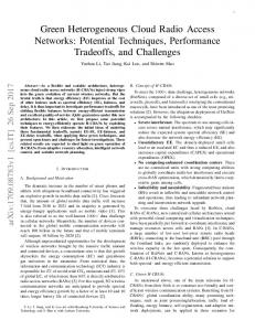
A subbands am , m ∈ MA and that on Type B subbands am , m ∈ MB are generated from the distribution qA and qB respectively. Furthermore, at each subframe, the user n n scheduling πA and πB are determined at each BS n based on the instantaneous channel quality indicator (CQI) of the direct links from the BS to the users. At the end of the LS subframes, the pico BSs deliver the � estimates of the data rates � Amacro and B (π ) , I π , a to the RRMS. ek (πA ) , eA A mB ,k B j k There are several advantages of the proposed hierarchical RRM. For example, each BS only requires the direct link CQI. Hence, this solution has low signaling overhead and good scalability on the complexity. Furthermore, only long term statistical information is needed at the RRMS. Hence, the solution is robust w.r.t. backhaul latency. B. Simulation Performance In this section, we consider a HetNet with 19 eNBs and 57 directional macro cells (three 120 degree sectors), as illustrated in Fig. 6. In each macro cell, there are 4 uniformly distributed pico BSs. There are 30 users in one macro cell, 2/3 of whom are clustered around the pico BSs, while others are uniformly distributed within the macro cell. The macro cells are separated in 500 meters, and the maximum transmit power of macro BSs and pico BSs are 46 dBm and 30 dBm, respectively. The PFS utility is considered. Key simulation parameters are summarized in Table II. The simulation was run over 1000 subframes. We compare the performance of the proposed algorithm with the following 3 baselines. • Baseline 1 (FFR with static synchronized ABS): Proportional fair scheduling and static synchronized ABS are used. The ABS is transmitted synchronously among the macro BS with 1/8 blanking rate. Fractional frequency reuse [17] with factor 1/3 is applied to the outer zone of each macro to protect the cell edge users. • Baseline 2 (FFR with dynamic synchronous ABS) [12]: Baseline 2 is the same as baseline 1, except that the ABS blanking rate is dynamically chosen to maximize the proportional fairness utility. • Baseline 3 (Clustered CoMP): 3 neighbor macro BSs and the associated pico BSs form a cluster for cooperative zero-forcing (ZF) [18] with per BS power constraint.
10
Parameters Network layout Number of UE per cell site BS transmit power Channel model Scheduling Thermal noise UE speed Bandwidth Number of subbands Cell selection bias
Values 19 eNBs, 3-cell sites, 4 picos per sector (site) 30 Macro: 46 dBm, Pico 30 dBm IMT-Advanced Channel Model [10, Annex B] Proportional Fair - 174 dBm/Hz 6 km/h 10 MHz 55 9 dB
Average cell capacity (Mbps) Macro cell I-users (Kbps) Pico cell I-users (Kbps) worst 10% users (Kbps)
Baseline 2 27.7 708 5498 715
Proposed 28.8 2351 5548 908
Gain 4% 232% 1% 27%
Table III: Performance evaluations on a HetNet with asymmetric network topology, where in each macro cell, the number of pico BS and the number of users are Poisson distributed with mean λp = 4 and λu = 30, respectively. Utility of Type−A users versus the number of superframes 1100
Table II: Key simulation parameters. 1000
900
Baseline 1 (Syn−Static−ABS) Baseline 2 (Syn−Dynamic−ABS) Baseline 3a (CO−MIMO, no latency) Baseline 3b (CO−MIMO 10ms latency Proposed
18 16
Mbps
14
ˆA Utility U
20
800
700
12
600
10
500
8 400 0
6
2
4
6
8 10 12 14 Number of superframes
16
18
20
4
Figure 8: Utility of the Type A users versus the number of super-
2 0
frames Cell Capacity (x2)
Macro cell−I user
Pico cell−I user
Worst 10% user
Figure 7: Throughput comparisons over different RRM schemes and in different backhaul latency scenarios. The proposed algorithm outperforms both baseline 1 and 2. It also outperforms baseline 3 when there is a backhaul latency.
1) Throughput Evaluations: Fig. 7 compares the throughput of different RRM schemes. The proposed scheme outperforms baseline 1 and 2 over all performance metrics. It also outperforms baseline 3 when 10 ms backhaul latency for the signaling among BSs is considered. These results demonstrate the superior performance and the robustness of the proposed hierarchical RRM scheme w.r.t. signaling latency in backhaul. Table III summaries the throughput performance of baseline 2 and the proposed scheme under asymmetric network topologies, where in each macro cell, the number of pico BS and the number of users are Poisson distributed with mean λp = 4 and λu = 30, respectively. The proposed scheme still outperforms baseline 2. In particular, it enjoys 27% throughput gain for the worst 10% users. As a comparison, the corresponding throughput gain for the worst 10% users is 6% in the symmetric topology in Fig. 7. This demonstrates that the proposed scheme can better adapt to dynamic network loading. Remark 3. In the simulations, we have fixed the cell selection bias β to be 9dB. For larger β, there will be more pico cell I-users and more severe cross-tier interference from macro BS to pico cell I-users. In this case, it is more critical to use better and more fine-grained eICIC schemes to control the cross-tier
interference. As a result, the performance gap between the optimization based ABRB control and those heuristic ABS controls becomes larger as increases. 2) Convergence of the Proposed Hierarchical RRM AlgoˆA in (9) of the Type A rithm: Fig. 8 shows the utility U users versus the number of super-frames. The utility increases rapidly and then approaches to a steady state after only 2 − 3 updates. The figure demonstrates a fast convergence behavior of Algorithm AO_A. Similar convergence behavior was also observed for Algorithm AO_B and the simulation result is not shown here due to limited space. C. Complexity We compare the complexity of the baselines and proposed RRM algorithms. The complexity can be evaluated in the following 3 aspects. 1) For the short term user scheduling, the proposed scheme and baseline 1-3 have the same complexity order of O (M K), while the baseline 4 has a complexity of O (C4 M K) [18], where C4 is a proportionality constant that corresponds to some matrix and vector operations with dimension Bc , and Bc = 15 is the number of BSs in each cooperative cluster. 2) For the long term ABRB control variables qA and qB , as they are updated by solving standard convex optimization problems in step 2 of Algorithm AO_A and AO_B respectively, the complexities are polynomial w.r.t. the number of the associated optimization variables. Specifically, for control variable qA , the complexity is polynomial w.r.t. the number of macro BSs N0 . For control variable qB , the complexity
11
is polynomial w.r.t. the size of the ABRB profile AB∗ : B∗ A ≤ |UB |. In addition, they are only updated once in each super-frame. 3) The ABRB profile AB∗ is computed using Algorithm B2 in every several super-frames to adapt to the large scale fading. In step 1 of Algorithm B2, the complexity of solving the convex problem (27) is polynomial w.r.t. Θ(i) ≤ |UB |+1. In step 2 of Algorithm B2, if the MWIS algorithm in [19] is used to solve problem (28), the complexity is O (|EI |), where |EI | is the number of edges in the interference graph GI (GT ) = {L, EI }.
Define the average mutual information region for subband m ∈ MB as: [ � |U | Rm , [xk ]∀k∈UB ∈ R+ B : {Qm ,πm }
� xk ≤ I m,k (Qm , πm ) , ∀k ∈ UB .
It can be verified that Rm , ∀m ∈ MA is a convex region |U | |U | in R+ A and Rm , ∀m ∈ MB is a convex region in R+ B . Moreover, due to the statistical symmetry of the subbands, we have Rm
VII. C ONCLUSION We propose a two-timescale hierarchical RRM for HetNet with dynamic ABRB. To facilitate structural ABRB design for cross-tier and co-tier interference, the M subbands are partitioned into Type A and Type B subbands. Consequently, the two timescale RRM problem is decomposed into subproblems PA and PB which respectively optimizes the ABRB control and user scheduling for the Type A and Type B subbands. Both subproblems involve non-trivial multi-stage optimization with exponential large solution space w.r.t. the number of macro BSs N0 . We exploit the sparsity in the HetNet interference graph and derive the structural properties to reduce the solution space. Based on that, we propose two timescale AO algorithm to solve PA and PB . The overall solution is asymptotically optimal at high SNR and has low complexity, low signaling overhead as well as robust w.r.t. latency of backhaul signaling. A PPENDIX A. Proof of Lemma 1 Define the average rate region as [� R, x = [xk ] ∈ RK + : xk ≤ r k (Λ) , ∀k .
Rm
= =
0
Rm0 , ∀m, m ∈ MA ,
(15)
0
Rm0 , ∀m, m ∈ MB .
(16)
Let RA = Rm , ∀m ∈ MA and RB = Rm , ∀m ∈ MB . From the convexity of Rm , ∀m and (15-16), we have R (qs ) = |MA | RA × |MB | RB . ∗
(17)
T [r∗1 , ..., r∗K ]
of Hence, for any Pareto point r = h ∗boundary i |UA | rk ∗ 1 ∈ R+ is a Pareto boundary R (qs ), |MA | rA , |MA | k∈UA h i |U | r∗ ∈ R+ B is a point of RA and |M1B | r∗B , |MkB | k∈UB Pareto boundary point of RB . Due to the statistical symmetry of the subbands, there exists an ABRB control policy and ∗ } such that |M1A | r∗A can a user scheduling policy {Q∗A , πA be achieved for all subbands m ∈ MA . Similarly, there exists an ABRB control policy and a user scheduling policy ∗ } such that |M1B | r∗B can be achieved for all subbands {Q∗B , πB m ∈ MB . Hence, r∗ can be achieved using the symmetric ∗ ∗ policy Λs∗ = {qs , Q∗A , Q∗B , πA , πB }. This completes the proof. B. Structural Properties of PA for General Cases
Λ
For any utility function that is concave and increasing w.r.t. e (GT ) must to the average data rates r, the optimal policy of P achieve a Pareto boundary point of R. Hence, we only need to show that any Pareto boundary point of R can be achieved by a symmetric policy. Define the average rate region under fixed qs as � [ R (qs ) , x = [xk ] ∈ RK + : {{Qm },{πm }}
� xk ≤ rk ({qs , {Qm } , {πm }}) , ∀k . Then we only need to show that any Pareto boundary point of R (qs ) can be achieved by a symmetric policy Λs = {qs , QA , QB , πA , πB }. Define the average mutual information region for subband m ∈ MA as: [ � |U | Rm , [xk ]∀k∈UA ∈ R+ A : {Qm ,πm }
� xk ≤ I m,k (Qm , πm ) , ∀k ∈ UA .
(14)
(13)
The formal definition of An and An is ( {a : a ∈ A; and an = 1} , n o ∀n ≤ N0 , An = 0 a : a ∈ A; and an0 = 0, ∀n ∈ Bn , ∀n > N0 , An
= A/An , ∀n ∈ {1, ..., N } .
(18)
The result in Observation 1 is formally stated in the following lemma. Lemma 2. For given CSI HmA ∈ H, BS index n ∈ {1, ..., N } and user index k ∈ Un ∩ UA , the following are � true: � 0
0
1) ∀a, a ∈ An , we have ΓnmA (a) = ΓnmA a and � 0 � � ImA ,k a, HmA , ρnmA = ImA ,k a , HmA , ρnmA ,
∀ρnmA ∈ ΓnmA (a). The same is true if we replace An with An . 0 2) For given ABRB patterns a ∈ An�, a� ∈ An and 0 0 user scheduling vector ρnmA ∈ ΓnmA a , there exists � ρnmA ∈� ΓnmA (a) such that ImA ,k a, HmA , ρnmA ≥ � 0 0 ImA ,k a , H1 , ρnmA . Proof: By Definition 2, there is no inter-cell interference for macro cell N-users. By the definition of ΓnmA (a), a pico
12
cell I-user k ∈ Un ∩ UA cannot be scheduled for transmission if any of the neighbor macro BSs in Bn is transmitting data subframe (i.e., the current ABRB pattern a ∈ An ). On the other hand, if all of the neighbor macro BSs is transmitting ABRB (i.e., the current ABRB pattern a ∈ An ), the interference from the macro BSs is negligible. Finally, by Definition 2, there is no inter-cell interference for pico cell N-users. Then Lemma 1 follows straightforwardly from the above analysis and the definition of An , An . Remark 4. Note that in the proof of Lemma 2, we have used the fact that the inter-cell interference seen at a N-user is negligible. We have also used Assumption 3, which states that the sets of neighbor macro BSs of the pico cell I-users belonging to the same pico cell are identical. For general cases, the result in Observation 2 is stated in the following theorem. Theorem 2 (Policy Space Reduction for QA ). Given a marginal probability vector that each � macro BS is transmitting ABRB qA = qjA , j = 1, ..., N0 , the optimal ABRB control policy of PA (GT ) conditioned on qA , denoted by Q∗A|qA , has the following synchronous ABRB structure: A A (a) Let ς be a permutation such that qς(1) ≤ qς(2) , ..., ≤ A ∗ qς(N0 ) . The support of QA|qA has only N0 + 1 active � ABRB patterns AA (qA ) =� aA (1), ..., aA (N0 + 1) , where � A A aA (j) = aA 1 (j), ..., aN0 (j) , j = 1, ..., N0 +1 with aς(i) (j) = 1, 1 ≤ i ≤ N0 + 1 − j and aA ς(i) (j) = 0, N0 + 1 − j < i ≤ N0 . A (b) Define q0A = 0, qN 0, and ς(N0 + 1) = 0 +1 � = 1,Aς(0) = A N0 +1. Then Q∗A|qA aA (j) = qς(j) −qς(j−1) , j = 1, ..., N0 + 1, and Q∗A|qA (a) = 0, ∀a ∈ / AA (qA ). Proof: By Lemma 2, for given marginal probabilities qA , the average mutual P information region will be maximized if we maximize P a∈An QA (a) for all 1 ≤ n ≤ N . For n ≤ A N � = qn . For n > N0 , we have P0 , we have a∈An QA A(a) a∈An QA (a) ≤ min qj , where the equality holds if and j∈Bn
only if QA has the structure in Theorem 2. This completes the proof. An example of synchronous ABRB is illustrated in Fig. 3. The following theorem is a general version of Observation 3.
∗ w.r.t. I mA ,k (QA , πA ), the optimal policy Q∗A , πA must achieve a Pareto boundary point of RmA . For given ABRB pattern a and BS n, define a region as [� [xk ]∀k∈UA ∩Un : xk ≤ ImA ,k (πA , a) . RnmA (a) , πA
It can be verified that RnmA (a) is a convex region. From Lemma 2, we have � 0� 0 (22) RnmA (a) = RnmA a , ∀a, a ∈ An . � 0� 0 RnmA (a) = RnmA a , ∀a, a ∈ An . (23) For convenience, define X X ∗ Q∗A (a) , Q∗A (a) ImA ,k (πA , a) / e∗k , a∈An
a∈An
e∗k
,
X
∗ QA (a) ImA ,k (πA , a) /
a∈An
X
Q∗A (a) .
a∈An
Then ∀n ∈ {1,P ..., N } , k ∈ UA P ∩ Un , we have ∗ ∗ ∗ ∗ ∗ (a) e + ) = Q I mA ,k (Q∗A , πA A� k a∈An a∈An� QA (a) ek . ∗ ∗ From (22-23) and the fact that I mA ,k (QA , πA ) ∀k∈U is a A Pareto boundary point of RmA , it follows that [e∗k ]∀k∈UA ∩Un is a Pareto boundary point of RnmA (a) , ∀a ∈ An and [e∗k ]∀k∈UA ∩Un is a Pareto boundary point of RnmA (a) , ∀a ∈ ◦ ∈ Ξ∗A An . Hence, there exists user scheduling policy πA ◦ ◦ satisfying ImA ,k (πA , a) = e∗k , ∀a ∈ An and ImA ,k (πA , a) = e� ∗k , ∀a ∈ An for� all k ∈ UA ∩ Un . Then it follows that ∗ ) ∀k∈U can be achieved by the control policy I mA ,k (Q∗A , πA A ◦ ∈ Ξ∗A . Q∗A , πA C. Proof of Corollary 1 The first part of the corollary follows straightforward from Theorem 2 and 3. We only need to prove that problem (9) is bi-convex. The average mutual information in (8) can be expressed as � P I mA ,k Q∗A|qA , πA = a∈Ab Q∗A|qA (a) ImA ,k (πA , a) k P + a∈Ab Q∗A|qA (a) ImA ,k (πA , a) k � 1 − qbAk eA k ∈ UMN k (πA ) , min q A eA (π ) − eA (π )� + eA (π ) , k ∈ U A A A PN j k k k j∈Bb (24) k A A min q e (π ) , k ∈ U A PI j k
Theorem 3 (Policy Space Reduction for πA ). ∗ There exists optimal user scheduling policy πA ∗ ∗ ∗ = for PA�(GT ) such that πA ∈ ΞA , where Ξ A , � 1 N n πA = πA , ..., πA : πA , ∀n, satisfies (19) and (20) . j∈Bb k � 0 � 0 n n πA (a, HmA ) = πA a , HmA , ∀a, a ∈ An , HmA ∈ H. (19) A where eA k (πA ) = ImA ,k (πA , a) , ∀a ∈ Abk , ek (πA ) = � 0 � 0 n n πA (a, HmA ) = πA a , HmA ∀a, a ∈ An , HmA ∈ H. (20) ImA ,k (πA , a) , ∀a ∈ Abk , UMN is the set of macro cell N-users, UPN is the set of pico cell N-users, and UPI Proof: Define the achievable mutual information region is the �set of pico� cell I-users. It is easy to verify that for subband mA as I mA ,k Q∗A|qA , πA , ∀k ∈ UA is a concave function w.r.t. qA [ � for fixed πA . Using the vector composition rule for concave RmA , [xk ]∀k∈UA : xk ≤ I mA ,k (QA , πA ) , function [20], the objective in (9) is also concave w.r.t. qA and QA ∈Q,πA thus problem (21) � (9) is convex � w.r.t. qA for fixed πA . For fixed � P ∗ qA , I mA ,k QA|qA , πA , ∀k ∈ UA is a linear function of the where Q = QA : a∈A QA (a) = 1; QA (a) ≥ 0, ∀a ∈ A . |U | n It can be verified that RmA is a convex region in R+ A . Since user scheduling variables {πA (amA , HmA )}. Hence problem the utility function UA (QA , πA ) is concave and increasing (9) is also convex w.r.t. πA for fixed qA .
13
D. Proof of Theorem 1 � � � � ˆA q(T +1) , π (T ) ≥ U ˆA q(T ) , π (T −1) . It is clear that U A A A A By � the assumption � �in Theorem� 1, we have ˆA q(T +1) , π (T ) > U ˆA q(T ) , π (T −1) if q(T ) , π (T −1) is U A A A A A A not a fixed point of F. Combining the above and the fact that ˆA is upper bounded, AO_A must converge to a fixed point U [˜ qA , π ˜A ] ∈ ∆. The rest is to prove that any [˜ qA , π ˜A ] ∈ ∆ is globally optimal for problem (9). Note that problem (9) is equivalent to the problem X wk u (Ik ) , s.t. [Ik ]∀k∈UA ∈ RmA . (25) max k∈UA
Since the objective in (25) is a concave function w.r.t. Ik , ∀k ∈ UA , and RmA is a convex region, the following Lemma holds. ∗ qA ,
∗ πA
Lemma 3 (Optimality Condition for (9)). A solution is optimal for problem (9) if�and only if� its average mutual ∗ ∗ information I mA ,k , I mA ,k Q∗A|q∗ , πA , k ∈ UA satisfies A
X k∈UA
� ∗ � ∂u (r) wk |r=I ∗m ,k I mA ,k − Ik ≥ 0, ∀ [Ik ]∀k∈UA ∈ RmA ∂r A
According to the step 1 of AO_A, for any ABRB pattern amA ∈ A and CSI realization HmA ∈ H, the user scheduling vector ρ˜nmA of BS n under π ˜A is the optimal solution of X � µ ˜k ImA ,k amA , HmA , ρnmA , (26) max n ρn mA ∈ΓmA (amA ) k∈U ∩U n A µ ˜k
where �
wk ∂u(r) ˜ ∂r |r=I
= �
and mA ,k
I˜ mA ,k
,
I mA ,k Q∗A|˜qA , π ˜A is the average mutual information ˜A, π ˜ A is under q ˜A . Combining (26) and the fact that q the optimal solution of problem (9) with� fixed π ˜A ,� we P P ˜k I mA ,k Q∗A|qA , π have ˜k I˜ mA ,k ≥ ˜A ≥ k∈UA µ k∈UA µ � � P ∗ A ˜k I mA ,k QA|qA , πA , ∀qA ∈ Q , ∀πA . This k∈UA µ ˜A, π implies that q ˜A satisfy the optimality condition in Lemma 3, and thus is the globally optimal solution. E. Optimization of ABRB Profile ~ (V) , [Ik (V)] For any MIS V, define I ∀k∈UB , where � ( � 2 log 1 + Pn σk,n , if lk ∈ V, Ik (V) , 0, otherwise,
Initialization: Find initial Θ(0) (0)
ΘT (GT ) such that V1
(0)
= (0)
(0)
(0)
V1 , ..., V Θ(0) | | = L. Set i = 0.
s.t. qˇj ∈ [0, 1] , ∀j and
P|Θ(i) | j=1
qˇj = 1,
V (i+1) = argmax
X
V∈ΘT (GT ) k∈U B
(i) ~ µ ˇk I k (V) ,
=
(28)
(i)
| P|Θ(i) | where µ ˇk = wk ∂u(r) � �. ∂r (i) (i+1) r= j=1 qˇj � � � � Ik Vj ˇ (i) ˇB Θ(i−1) > ε, let i = i + 1 −U If U B Θ and return to Step 1. Otherwise, terminate theo algorithm with n � ∗ (i) (i+1) ∗ Θ∗ , V1 , ..., V|Θ = Vj : qˇj > 0 and AB∗ = ∗| � B∗ � � ∗ B∗ B∗ a (j), j = 1, ..., |Θ | , where (j) = aB∗ 1 (j), ..., aN0 (j) � a B∗ � B∗ ∗ ∗ with an (j) = 1, ∀n ∈ N Vj and an (j) = 0, ∀n ∈ / N Vj .
The convergence and asymptotic optimality of Algorithm B2 is proved in the following theorem. Theorem 4 (Asymptotically Optimal ABRB Profile). Algorithm B2 always converges to an ABRB profile AB∗ B∗ with A ≤ |UB |. Furthermore, the converged result AB∗ is asymptotically optimal for high SNR. i.e. �� lim UB∗ − UBI AB∗ /UB∗ = 0, where Pn = αn P, ∀n = P →∞ 1, ..., N0 for some positive constants αn ’s, and UB∗ is the optimal objective value of PB (GT ). Proof: Consider problem PˇB (GT ) which is the same as PB (GT ) except that there are two differences: 1) the fading channel H (t) is replaced by a deterministic channel with the channel gain between BS n and user k given by the 2 corresponding large scale fading factor σk,n ; 2) an additional constraint is added to the user scheduling policy such that any two links lk , lk0 having an edge (i.e., e (lk , lk0 ) = 1) in the interference graph GI (GT ) cannot be scheduled for transmission simultaneously. It can be shown that the optimal solution of problem PˇB (GT ) is asymptotically optimal for PB (GT ) at high SNR. Moreover, using the fact that the achievable mutual information region n in the deterministic o ~ (V) , ∀V ∈ ΘT (GT ) channel is a convex polytope with I as the set of Pareto boundary vertices, it can be shown that PˇB (GT ) is equivalent to the following problem � �P �� P |Θ| max max w u q ˇ I (V ) , (29) j k∈UB k j=1 j k ˇ ˇ ∈Q(Θ) q
s.t. Θ ⊆ ΘT (GT ) , |Θ| ≤ |UB | + 1,
� ⊆
∪ V2 ... ∪ V Θ(0) | | ˇ ): For fixed Θ(i) , obtain the Step 1 (Update the coefficients h iq ˇ (i+1) = qˇj(i+1) optimal solution q of the following j=1,...,|Θ(i) | convex optimization problem � � � � �� P|Θ(i) | (i) ˇB Θ(i) , max P U w u q ˇ I V , (27) j k k j=1 j k∈UB ˇ q
(i+1) n Step 2 (Update o the set of MISs Θ): Let Θ (i) (i+1) (i+1) (i+1) Vj : qˇj >0 ∪V , where V is given by
Θ
The ABRB profile optimization algorithm is given below. II Algorithm B2 (Algorithm for solving �PB (GT )):
(i) ˇ = [ˇ where q qj ]j=1,...,|Θ(i) | , and Vj is the j th MIS in Θ(i) .
where Vj is the j th MIS in Θ. To complete the proof of Theorem 4, we only need to further prove that Algorithm B2 converges to the optimal solution of problem (29). Using the fact that any point in a (|UB | − 1)-dimensional convex polytope can be expressed as a convex combination of no more than |UB | vertices, it can be shown that there are at most ˇ (i+1) in step 1 of Algorithm B2. |UB | non-zero (i) elements in q Hence Θ ≤ �|UB | + 1, ∀i. �Moreover, it can be verified ˇB Θ(i+1) > U ˇB Θ(i) if Θ(i) is not optimal for that U ˇB (Θ) is upper (29). Combining the above and the fact that U ˇB (ΘT (GT )), Algorithm B2 must converge to bounded by U the optimal solution of (29). This completes the proof. Remark 5. In step 2 of Algorithm B2, problem (28) is equivalent to finding a maximum weighted independent set
14
(MWIS) in the interference graph G�I (GT ) with �the weights of (i) 2 the vertex nodes given by µ ˇk log 1 + Pn σk,n . The MWIS problem has been well studied in the literature [19]. Although it is in general NP hard, there exists low complexity algorithms for finding near-optimal solutions [19]. Although the Asymptotic global optimality of Algorithm B2 is not guaranteed when step 2 is replaced by a low complexity solution of (28), we can still prove its monotone convergence. R EFERENCES [1] M. Ebrahimi, M. Maddah-Ali, and A. Khandani, “Throughput scaling laws for wireless networks with fading channels,” IEEE Trans. Inf. Theory, vol. 53, no. 11, pp. 4250 – 4254, Nov. 2007. [2] D. Gesbert and M. Kountouris, “Rate scaling laws in multicell networks under distributed power control and user scheduling,” IEEE Trans. Inf. Theory, vol. 57, no. 1, pp. 234 – 244, Jan. 2011. [3] D. Gesbert, S. Kiani, A. Gjendemsj et al., “Adaptation, coordination, and distributed resource allocation in interference-limited wireless networks,” Proceedings of the IEEE, vol. 95, no. 12, pp. 2393–2409, 2007. [4] E. Altman, T. Boulogne, R. El-Azouzi, T. Jimenez, and L. Wynter, “A survey on networking games in telecommunications,” Computers & Operations Research, vol. 33, no. 2, pp. 286–311, 2006. [5] A. L. Stolyar and H. Viswanathan, “Self-organizing dynamic fractional frequency reuse in ofdma systems,” in INFOCOM 2008. The 27th Conference on Computer Communications. IEEE. IEEE, 2008, pp. 691–699. [6] R. Irmer, H. Droste, P. Marsch, M. Grieger, G. Fettweis, S. Brueck, H. Mayer, L. Thiele, and V. Jungnickel, “Coordinated multipoint: Concepts, performance, and field trial results,” IEEE Communications Magazine, vol. 49, no. 2, pp. 102–111, 2011. [7] H. Dahrouj and W. Yu, “Coordinated beamforming for the multicell multi-antenna wireless system,” IEEE Transactions on Wireless Communications, vol. 9, no. 5, pp. 1748–1759, 2010. [8] Q. Shi, M. Razaviyayn, Z.-Q. Luo, and C. He, “An iteratively weighted MMSE approach to distributed sum-utility maximization for a MIMO interfering broadcast channel,” IEEE Trans. Signal Processing, vol. 59, no. 9, pp. 4331–4340, sept. 2011. [9] LTE Advanced: Heterogeneous Networks, Qualcomm Incorporated, 2010. [10] E-UTRA; Further Advancements for E-UTRA Physical Layer Aspects, 3GPP TR 36.814. [Online]. Available: http://www.3gpp.org [11] Y. Wang and K. I. Pedersen, “Performance analysis of enhanced intercell interference coordination in lte-advanced heterogeneous networks,” in Vehicular Technology Conference (VTC Spring), 2012 IEEE 75th. IEEE, 2012, pp. 1–5. [12] J. Pang, J. Wang, D. Wang, G. Shen, Q. Jiang, and J. Liu, “Optimized time-domain resource partitioning for enhanced inter-cell interference coordination in heterogeneous networks,” in Wireless Communications and Networking Conference (WCNC), 2012 IEEE. IEEE, 2012, pp. 1613–1617. [13] M. Hong, R.-Y. Sun, H. Baligh, and Z.-Q. Luo, “Joint base station clustering and beamformer design for partial coordinated transmission in heterogenous networks,” 2012. [Online]. Available: http://arxiv.org/abs/1203.6390 [14] J. Mo and J. Walrand, “Fair end-to-end window-based congestion control,” IEEE/ACM Transactions on Networking, vol. 8, no. 5, pp. 556– 567, Oct 2000. [15] F. Kelly, A. Maulloo, and D. Tan, “Rate control for communication networks: Shadow price proportional fairness and stability,” J. Oper. Res. Soc., vol. 49, pp. 237–252, 1998. [16] H. Kushner and P. Whiting, “Convergence of proportional-fair sharing algorithms under general conditions,” IEEE Transactions on Wireless Communications, vol. 3, no. 4, pp. 1250–1259, 2004. [17] R. Ghaffar and R. Knopp, “Fractional frequency reuse and interference suppression for OFDMA networks,” in Proceedings of the 8th International Symposium on Modeling and Optimization in Mobile, Ad Hoc and Wireless Networks, 2010, pp. 273–277. [18] O. Somekh, O. Simeone, Y. Bar-Ness, A. Haimovich, and S. Shamai, “Cooperative multicell zero-forcing beamforming in cellular downlink channels,” IEEE Trans. Inf. Theory, vol. 55, no. 7, pp. 3206–3219, 2009. [19] W. Brendel and S. Todorovic, “Segmentation as maximum weight independent set,” in NIPS, pp. 307–315, 2010.
[20] S. Boyd and L. Vandenberghe, Convex Optimization. University Press, 2004.
Cambridge