We define Hybrid Heterogeneous Hierarchical Modelling (HHH Modelling) as any model .... Complex models are made up of at least two hierarchical levels.
Hybrid Heterogeneous Hierarchical Models for Knowledge-Based Autonomous Systems
Victor T. Miller University of Florida, Department of Aerospace and Mechanical Engineering Sciences 231 Aero building Gainesville, Florida, 32611 Paul A. Fishwick University of Florida, Department of Computer and Information Science 301 Bldg CSE Gainesville, Florida, 32611 ABSTRACT
Complex High Autonomy Systems generally require the use of multiple modelling formalisms and multiple levels of abstraction in order to accurately and efficiently describe their dynamic characteristics. It is often necessary to integrate several modelling formalisms together if we want to reason about, simulate or analyze a system. Moreover, the use of a hierarchical representation helps us to more intelligently organize the models during development. We discuss a general modelling approach called Hybrid Heterogeneous Hierarchical Modelling (HHH Modelling) which supports multiple representations and hierarchical development of Knowledge-Based Autonomous System Simulations. In this context, we discuss methods to describe how different modelling formalisms may interact with each other in terms of data input/output and inter-model coordination (coordination between two different models). However, our major focus will be on intra-model coordination. Intra-model coordination is a method by which the components of a model can be coordinated with other models. For instance, when the state of a finite state machine is coordinated with a Petri net. The benefits of intra-model coordination become clear when hybrid analysis methods (symbolic, numerical, and knowledge-based) are applied to a single model.
1.0 INTRODUCTION
The need to efficiently represent each level of a Knowledge-Based Autonomous System model (KAS model) has become important for many reasons. Some modelling formalisms capture certain aspects of system behavior
better than others (developmental efficiency). Other modelling formalisms may provide the means to discern important features that are not evident in other formalisms (conceptual efficiency). The use and benefits of multiple models types has
been
investigated in theories such
heterogeneous inter-level refinement[Fish91a].
as multifacetted modelling [Zeig84] and
The general concept of heterogeneous modelling which we
discuss in this paper draws upon research in multi-models, combined models, multifacetted models, homomorphic models, and abstract models. One of the ways of advancing the field of simulation requires improving the available modelling methods [Ören]. Heterogeneous modelling improves methods by aiding in the development, maintenance, simulation, and conceptualization of KAS models. It does this by providing a variety of succinct formalisms and the techniques for integrating them.
Using hierarchies to help organize models has also become a standard modelling approach. However, in addition to developmental advantages, hierarchies can help during analysis. Qualitative and quantitative analysis of a partial or complete model requires substantial knowledge about the model’s structure. An investigator may be interested in qualitative information in one question (i.e., "Will the two robots collide before or after main system shutdown?") or numerical information in another (i.e., "How many seconds before main system shutdown?"). These questions require different levels of abstraction (and therefore different levels of implementation and/or representation). Hierarchical modelling provides, by its very nature, different levels of abstraction with corresponding representations capable of providing information appropriate for reasoning at several levels of abstraction.
A growing but still under represented topic in modelling research is the ability to analyze a single model using symbolic, numerical, and interpretative techniques. We define Symbolic techniques as mathematical analysis which involves manipulating algebraic or differential equations. With the increased use and availability of programs that do symbolic mathematics, it is becoming increasingly easier to automate symbolic analysis (especially of well-known modelling formalisms). Numerical techniques refers to traditional computational simulation methods and numerical approximation. Interpretation methods are those that are related to the field of Artificial Intelligence and Knowledge Engineering. These range from fuzzy or quantitative simulation [Fish91b] up to and including logic methods and semantic networks. In general, Hybrid analysis (symbolic, numeric, and interpretative) requires different model specification strategies and processes for each type of analysis. This duplicates a substantial amount of effort on the part of the investigator. It also makes it impossible for information gained in one type of analysis to help or guide a technique in another type of analysis (unless the investigator transmits "by hand" this information from one modelling formalism to the other ).
TR92-038 Computer Information Sciences, University of Florida
2
We define Hybrid Heterogeneous Hierarchical Modelling (HHH Modelling) as any model theory that supports hierarchical development of KAS models by integrating or combining different modelling formalisms and supports automated analysis in terms of symbolic, numeric, and interpretative techniques. We assume that such a model theory will have practical use only when implemented on a computer. Therefore, particular attention must be focused on a theory which is to be used effectively by an investigator in a computer environment.
A legitimate approach to HHH modelling is to develop a new modelling formalism which is oriented toward KAS models. We believe that in order to provide insights into the complex behavior of KAS models through simulation and reasoning methods, efficient and succinct representations must be used to describe all aspects of behavior which are pertinent to the investigator. Furthermore, we assert that no one modelling formalism will provide such a representation. This assertion is based upon the pragmatics of model building. Specific modelling formalisms are used by investigators because they are convenient to use, have preferable attributes, or fulfill some pragmatic requirement [Roth]. We clearly identify two dilemmas to investigators of KAS systems. First, since pragmatic issues are dictated by the investigators preferences and convenience, and pragmatic issues vary within different sections of large complex systems, a single modelling formalism locks the investigator into a method which is neither preferable nor convenient.
The second dilemma concerns the trade-offs between convenience and generality. For example,
queuing
networks may be efficient for modelling arrival/departure behavior, but not general enough for the modelling of complex KAS models. Similarly, simulation languages such as GPSS[Schr] are general enough to be used for almost all types of simulation, but lack the developmental efficiency, conceptual efficiency and convenience of mathematical based modelling formalisms. Additionally, simulation languages have traditionally lacked symbolic and interpretative analysis methods. In short, the more general a formalism becomes, the less convenient it is to use.
With this in mind, an HHH modelling theory which is based on coordination of existing modelling formalisms is an attractive alternative to developing an all-encompassing, completely generalized, single formalism. Since modelling formalisms such as queuing networks and finite state automata have proven to be powerful methods, but limited to specific domains, a coordination of these modelling formalisms, which keeps the representational power of each formalism intact, should foster more complete investigations of complex high autonomy systems. Additionally, by coordinating established modelling formalisms, we reduce the learning curve needed to
TR92-038 Computer Information Sciences, University of Florida
3
understand the theory. HHH modelling can be accomplished by letting the investigator use an appropriate modelling formalism to describe a particular component of the system and then allowing a coordination of this formalism with models that describe other system components. The investigator may also need to re-implement sub-components of a particular model as new information is gained during development and analysis (perhaps with a different modelling formalism). Efficiency and succinctness are supplied by the mathematical formalism whereas the coordination of several formalisms increases the generality. It should be noted that our emphasis is on the coordination between modelling formalisms rather than on new interpretative, symbolic or numerical analysis methods.
In the next section, we briefly introduce the underlying modelling paradigm which we propose. Then, we will present some basic assumptions and definitions which we will use throughout the rest of this paper. This involves some minor modifications of the formalisms which allow for the coordination described in the following sections. The modifications will not alter the behavior of the formalisms. In some cases, however, the computational power of the formalisms may increase. General system theory (GST) will be the foundation upon which we develop a theory for HHH modelling. GST has already been used for multi-models[Präh]. However, the GST definition does not have sufficient structure for what we call component coordination (GST does handle model coordination and was therefore a good starting point). Also, GST does not clearly integrate with domain independent knowledge-base reasoning techniques. Therefore, in order to support HHH modelling, we have extended GST by including connectivity and abstraction concepts. We call the extended theory hybrid model theory.
Hybrid model theory is a direct attempt to simultaneously embrace two themes which are directly related to HHH modelling. First, it expands, clarifies, and establishes a solid mathematical foundation for the notion of heterogeneous refinement as introduced in [Fish92]. In Fishwick and Zeigler’s presentation, the concept of heterogeneous refinement was described as a method which helps bridge the gap between AI and simulation models in a formal manner. However, the refinement process was carried out "by hand." Hybrid model theory expands the concept and provides a foundation that allows heterogeneous refinement to be automated. Second, and most important, hybrid model theory furnishes a premise for hybrid analysis of a system represented by a refined multi-model. The extent of hybrid model theory is currently focused on a single model. This is complementary to theories, like general system theory , which deal with classes of models.
It should be noted that hybrid model theory is a foundation which allows HHH modelling to be implemented. There are certainly other approaches. However, with hybrid model theory, we have chosen an approach much like compiler theory. All programming languages can be described by compiler theory, yet there are many
TR92-038 Computer Information Sciences, University of Florida
4
different types of programming languages which suit different purposes. Our intention with hybrid model theory is similar; We do not expect investigators to use hybrid model theory as a formalism. Hybrid model theory is used to explain, mathematically, the commonalties and differences between modelling formalisms. We have found that with this foundation,
coordinating different formalisms such as Petri nets and block diagrams can be
substantiated since the relationship between them has been formally established.
The next section outlines the modelling paradigm which we have developed to support HHH modelling. Also, an informal characterization of hybrid model theory is given. Section three provides some background material and presents a few key concepts used in hybrid model theory. In section four, the benefits that HHH modelling using hybrid model theory provide are demonstrated by the modelling of an Automated Flexible Manufacturing System (AFMS). Traditional formalisms such as Petri nets, Markov systems, and block diagrams are used to efficiently create a hierarchical model.
2.0 BASIC MODELLING PARADIGM
We have defined the distinction between a formalism and a theory as a difference in generality.
For our
purposes, a formalism (Petri net, state machine) has relatively clear semantics pertaining to its use and dynamic properties. We define a theory (system theory, computation theory) as a more generalized mathematical system which usually can describe any known formalism. Because of the generality, automated interpretation is typically infeasible.
We have chosen five common modelling formalisms as representatives of different modelling techniques. These fall into two general classes: state models or functional models. State machines and Markov systems were chosen as examples of state model formalisms. Queuing networks, Petri nets and block diagrams were chosen to represent functional model formalisms. We preserve the diagrammatic aspects of each specific modelling approach (i.e., places as circles and transitions as line segments in Petri nets) since these aspects are a fundamental part of the "way we think about models"; there is no attempt to "homogenize" modelling to force all models to look like either data flow diagrams or state transition networks. Also, we have chosen model types which have an equivalent graph or network representation. This is necessary in hybrid model theory in order to support knowledge-based reasoning methods (interpretation). However, we do not believe this has reduced the effectiveness of our discussion since many modelling formalisms have graph or network equivalents.
TR92-038 Computer Information Sciences, University of Florida
5
More specifically, we require that a formalism be represented by a directed graph. Arcs (edges) which lead out of a node are output arcs and arcs leading into a node are input arcs. Nodes in the graph represent either computational or storage (sub) models. As with most theories of modelling, there are two basic types of models: atomic and complex. However, in hybrid model theory a state machine, Petri net etc. are not atomic models but complex ones. Complex models are made up of at least two hierarchical levels. The first level is called a controller model. As will be shown, for a variety of formalisms only three controller models are necessary. The second level in the hierarchy is made up of atomic models called component models. This split-level approach to models is demonstrated in Figure 1.
Input
Controller Model
Output
Component Model 1
Component Model 2
Component Model 3
Figure 1 Two level representation of a model formalism.
As can be seen from Figure 1, data (or control) input and output are directed into the controller model. The component models (nodes in the graph) may or may not have data input and output. Depending on the type of controller, edges in the graph will either indicate control flow or data flow. This dual functionality has been captured in the controller models interpretation of its components. Only under direction of the controller model is data input and output passed down to and up from the component models. This, at first, seems very inefficient, however; when the model is compiled for numerical analysis(simulation), this inefficiency can be be removed if and only if there has been no sub-modelling (section four). When using interpretation techniques, this split-level method allows for more generalized knowledge. When analyzing the model symbolically, it allows combined results from different types of symbolic analysis.
We currently classify formalisms based upon three attributes: 1) how they use time, 2) the type of data they use, and 3) the type of controller. There are in total four types of controllers which we are currently using: parallel,
TR92-038 Computer Information Sciences, University of Florida
6
state, selective, and group. All four of these controllers contain the connectivity of the components they control (the graph). A parallel controller model controls component models in which all components are active simultaneously. Edges between the components are interpreted by the controller as data paths. Formalisms which have this type of controller are block diagrams, queuing networks, confluence graphs, bond graphs, and neural networks. A state controller model controls components in which only one component can be active. The controller, under direction of the components, keeps track of the current active component. Edges between the components are interpreted by the controller as control paths. Formalisms which have state controllers are Markov systems and state machines. The selective controller is the most complex. This controller controls two types of component models: functions and storage. A selective controller first determines which function components can be activated and then non-deterministically chooses one them to activate. The function components may use any of the storage components for data input and output. Edges between the components are interpreted by the controller as data paths. Formalisms which use selective controllers are Petri nets and Expert Systems (transitions and rules are the function components, places and variables are the storage components). A group controller is a parallel controller in which the components are complex models. The group controller allows hybrid model theory to encompass traditional model coordination (coupling).
Data Attributes Continuous-Time Continuous-Value
State
Continuous-Value
Discrete Value
BlockDiagrams
QueuingNetwork
Deterministic
StateMachine
StateMachine
StateMachine
FiniteStateAutomata
Stochastic
MarkovSystem
MarkovSystem
MarkovSystem
MarkovSystem
ExpertSystem
ExpertSystem
ExpertSystem
PetriNet, ExpertSystem
Parallel Contoller Type
Discrete-Time
Discrete Value
Selective
DigitalCircuits
Figure 2 Categorization of Models
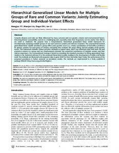
The type of data which may used by a formalism has two general attributes: value and time. Both of these attributes may be either continuous or discrete. This expands the typical continuous versus discrete concept of a signal in system theory. A discrete signal is too ambiguous of a categorization when combining symbolic analytical techniques and for interpretation techniques of different formalisms. It must be known whether a signal is discrete (continuous) over its values and over time. Figure 2 shows how the data signals and controllers combine to for a variety of different modelling formalisms. Notice that some formalisms have been used with a variety of different types of data.
The third element which classifies a formalism is the way in which time is used. There has already been significant advances in combined discrete-event and continuous model simulation through the use of time
TR92-038 Computer Information Sciences, University of Florida
7
bases[Präh]. This will form the foundation for hybrid model theory. Once again however, we extend the time description to include elements necessary for symbolic and interpretation methods. We call this extension a Time Domain. The concept of a time base which is used in system theory becomes one of five elements used in a time domain. The most important of which is the time map function. The time map of a time domain is a function from the reals into the time base of the model. This allows coordination of all models with a common time base. Each model is responsible for mapping the common clock into local time. This concept, along with local model states, allows hybrid model theory to be easily translated into a distributed simulation when numerical analysis is required. Thus, there is no main event-queue during numerical analysis. All events are stored locally in a model.
The other elements of a time domain relate information concerning the semantics of the time base. Currently, we are using three elements: a zero point, a delta time, and a magnitude function. The zero point signifies the minimum time required for a model to change an output signal given a change in the internal state. The delta time signifies the minimum time required for a model to change its internal state. The magnitude function maps a time from the time base into the integers. This function permits a model to specify significant magnitude changes in time.
The formal theory and a few examples of the above concepts are presented in the following sections. However, with these concepts briefly outlined we can now introduce an overview of how different models can be coordinated in an inter-model and intra-model fashion.
Group Controller Model
state machine
Petri net
queuing net
Figure 3 Inter-model Coordination
TR92-038 Computer Information Sciences, University of Florida
8
Inter-model coordination is another term for model coupling [Zieg84, Wym]. Because hybrid model theory has incorporated system theory(next section), this type of coordination will not be extensively explained. Model coupling can be found in most system theory literature. From Figure 1, it should be clear that complex models of varying types can be coordinated through their data input and output. A collection of these models can then be grouped into a new model (see Figure 3).
An important advantage in hybrid model theory, is that the inter-model coordination (coupling) need not be static. That is, during execution or analysis, since the controller model contains the connectivity along with the functionality, the couplings can be dynamic; The controller can manipulate the connectivity of its components. We have not included in this paper any modelling types which implement this; However, it becomes useful in certain types of neural network formalisms. For instance, as weights between neurons become zero.
Intra-model coordination involves the replacement of a component model with a new complex model. This is quite different from inter-model coordination where, for instance, the output of a state machine is the input to a block diagram. In intra-model coordination, for example, a state component in a state machine controller model is replaced by a block diagram model [Fish92]. The controller model of a state machine essentially keeps track of several component models. Whether these components are simple state models which are based on conditions (input = ’a’ etc.) or complex models like block diagrams is inconsequential to the controller. The only requirement is that the communication between the controller and its components be standardized in a formal protocol. The same type of argument holds true for parallel, group and selective controllers. In section four, we present the theoretical details of controller-component intra-model coordination and section five exemplifies how intra-model coordination can be useful in the development and analysis of KAS models.
3.0 BACKGROUND
3.1 Automated Flexible Manufacturing System (AFMS)
For exemplary purposes, in section four and five we will model a part of an Automated Flexible Manufacturing System (AFMS). Therefore, we give a brief introduction here so that the examples are clear. An AFMS is a system consisting of several work cells and a transit system(see Figure 6). A computer system acts as the controller for the entire system (i.e., scheduling operations, resolving conflicts). The transit system can vary from automatic guided vehicles (AGVs) to simple conveyor systems. Each work cell is a logical unit consisting of a set of machines or robots. Within a work cell many different types of operations may occur; for example, milling,
TR92-038 Computer Information Sciences, University of Florida
9
drilling, pressing, or assembly. Machines and robots operate on parts (these may simply be raw materials). Parts are collected in trays called palettes.
Materials
Storage
Machining Work Cell
Assembly Work Cell
Load / Unload docks
Figure 6 AFMS Floor diagram
The general sequence of events in the AFMS entails transporting palettes to a work cell, performing specific operations, and then transporting the palettes back to a storage area. The complexity is associated with the control of this system. This involves scheduling operations,
allocating machine and transport resources,
buffering intermediate palettes and final assemblies, and decisions as to when parts are to be manufactured to meet current or projected demands. Since most of the decisions are handled by a computer, and the work cells and transit system are automated, this system has a high degree of autonomy. Figure 7 shows a conceptual diagram of the operations in an AFMS.
storage
materials
n1
n2
Load
unload
transfer
load AGV
dock
n3
unload
pick-up conveyor
n4
transfer
robot cell
n5
n6
return
Figure 7 Abstract Model of AFMS
3.2 System Theory
There are several different ways each formalism used in this research can be represented. This produces a permutation of possible mapping techniques from formalism to formalism. General system theory will be used as a starting point towards developing a common representation for the formalisms which we have chosen. This section introduces the mathematical foundation of general system theory for background purposes; a more complete presentation can be found in[Wym]. A System is a 6-tuple Z = (T, I, S, A, B, δ), where
TR92-038 Computer Information Sciences, University of Florida
10
T is the time base, I S A B δ
is a non empty set called the input, is a non empty set called the system states, is an admissible set of input functions f: T → I, is a set of functions f: S → S called the Behavior, and is a function f: A x T → B called the transition function.
The time base , T, is typically the reals (ℜ) or the integers (ℑ). When T = ℜ, the system is said to be a continuous system. When T = ℑ, the system is said to be a discrete system. If we consider the system to be like a function, then the input set (A) along with a time (t) is essentially the domain. The set of system states (S) varies greatly from formalism to formalism; however, it usually has the structure of an n-tuple or vector. For instance, the states of a state machine are usually represented by a simple set and the states of a continuous system are typically represented by a vector space on a field (such as ℜn).
The admissible input functions represent the class of input schedules or input histories. Given a time segment t ∈T, a function in A gives the input presented to the system. This indicates that the inputs to the system must be predetermined in order to define the system. The behavior functions B, define the class of system sequences (discrete systems) or trajectories (continuous systems). The transition function generates a behavior function for a given input function and a time segment. Given an input function, initial conditions, and a transition function, the behavior of the system is completely deterministic. One can extend a system structure to include output by adding the following definitions,
O
is a non empty set called the output and
λ
is a function f: S x T → O called the output function.
3.3 Time Domains
The standard system theory notion of a time base will be used to specify the range of time values used by models in hybrid model theory. A time base is structure consisting of a set and two operators: addition and
TR92-038 Computer Information Sciences, University of Florida
11
comparison. The addition operator and the set must be an abelian group. The comparison operator and the set must form a linear order which is preserved under the addition operator.
Time Base an abelian group a linear order preserved under + Typical time bases are the reals ℜ and integers ℑ with + and ≤ defined appropriately. These time bases are abbreviated by Tℜ and Tℑ. When a model or formalism has no time base, the null time base can be used. It is defined as T†. The symbol † will be used to indicate null or undefined values.
Base
T = {†}
Group
† = identity, operator † + † = †, inverse † =† -1
Linear Order † ≤ †
A time domain is built upon a time base. During the interpretation of a model, information about how the time is is used by the model must be present. The time domain will serve this purpose. A time domain is a named set (a special kind of structure introduced shortly) which consists of five elements: time base, delta time, zero time, time map, and a magnitude function. A time domain TD is structured set such that
T dt zero t[] m[]
Time base small time in T, i.e. a significant change in time t ∈ T such that everything < t is considered zero time mapping ℜ -> T magnitude function T -> ℑ such that m[zero] = 0
The use of a time domain can be exemplified by the following two examples.
Human Time T = Tℜ
Computer Time T = Tℜ
dt = 10 millisecond zero = 100 milliseconds t[] = identity m[r] = integer[r/10*zero ]
dt = 1 picosecond zero = 1 nanosecond t[] = identity m[r] = integer [r/2*zero]
TR92-038 Computer Information Sciences, University of Florida
12
Although the time base is the same, there are significant differences in how time effects human and computer systems. The zero time stipulates what times are to be considered as instantaneous. That is, in times < zero the system can not react to input. Note this is different from the delta time dt. The delta time indicates what times are significant in changes in state. For instance, we assume that a human can sense things in 10 milliseconds but can not react until 100 milliseconds. Likewise in a picosecond, changes in transistors are important, but a cpu reacts only in nanoseconds (i.e. memory accesses).
The time mapping is used to relate all time domains to Tℜ. This will be further discussed in section five. The magnitude function is used to signify a constant state between systems. For example, for a time period of 0.9 seconds, the human magnitude function m[0.9] = 0 while the computer magnitude function m[0.9] = 450x106 . For all practical purposes, in a time period of 0.9 seconds, a computer systems can assume a human system is constant. The magnitude comparison can be used to circumscribe the system when any of the three types of analysis (symbolic, numerical, interpretation) are required.
3.4 Named Sets
In systems theory, a convenient representation of "assignment" is represented by a structured set [Zeig76, Zeig84]. In this paper, we simply call these sets named. Formally, a named set is a structure with
S - a set (entities) V - ordered set (parameters) R - indexed set (V is index) R is the range A - assignment A: S -> Πi Rv i A useful accessing function called a projection allows the values of parameters to be obtained from the named set. It is defined from the entities into the range of a value set Vi . Formally, a projection is defined as
projv :S ->R v i As an example consider the assignment of a persons age and sex. We can create a named structure by defining the following
TR92-038 Computer Information Sciences, University of Florida
13
S = {Tom, Jane} V = {age, sex} R = { (age, [0, 130]), (sex,{male, female}) } A = { (Tom, (23, male) ), (Jane,(21, female)) }
A projection function on the age parameter and an application of the function is given by
projage = { (tom, 23) , (Jane, 21 )} projage [Tom] = 23 The projection function will be abbreviated in this paper with the dot notation similar to typical programming languages.
Tom.age = 23
represents
projage[Tom] = 23
The conceptual and pragmatic convenience of named sets is the basis of building a fact-base for a knowledgebase system in hybrid model theory. For example, if we consider the projection function as a predicate, then the Prolog style predicate sex[Tom, male] and the projection function Tom.sex = male can be considered equivalent. When reviewing example models which used graphical formalisms, we found that labeling arcs and nodes with text was always carried out. This is extremely valuable to humans during the development of a model. There was also a tendency to be fairly consistent with the usage of verbs and nouns on arcs and nodes. Since the interpretation of nodes and arcs in these formalisms is relatively straight forward (i.e. arcs and nodes have relatively well defined semantics in each of the formalisms), we have included the text as part of hybrid model theory by using Named Sets. This will be further explored in the fifth section.
4.0 HHH MODELLING USING HYBRID MODEL THEORY
Hybrid model theory is a combination of general system theory (GST), named sets, and graph theory. The combination of GST and Named sets has been successfully used in Multifacetted Modelling[Zeig] and derivations thereof. In a sense, one could argue that hybrid model theory is a derivation of GST. Mathematically, this may be correct. However, there are significant differences of which those familiar with GST should be aware. These differences arose from the requirements needed for HHH modelling .
TR92-038 Computer Information Sciences, University of Florida
14
First, hybrid model theory is not to be used by the investigator. It is not a modelling formalism. It is an intermediate form between more efficient and effective formalisms such as Petri nets, queuing networks, and block diagrams. Second, hybrid model theory emphasizes a top-down approach to constructing a model (Although building bottom-up is possible). The idea behind hybrid model theory is take a model which is partially correct in describing a system’s behavior and refine only those components which do not coincide with observed data or system specifications.
Third, hybrid model theory currently
focuses on the analysis of a single system under
development. HHH modelling and hybrid model theory are meant to provide the foundation for an computer environment
which allows for the creation and investigation of system models, not
the classification,
identification, comparison and retrieval of already constructed and understood system models. Hybrid model theory deals with the alteration and investigation of incomplete or incorrect models.
With this in mind, we introduce the definition of a model in hybrid model theory[Mill93]. This is, a model M is a named set such that M =
Η :Component Α : Edge Χ : Input
Ψ : Output
Θ : State τ : Time Domain β : Initialize function δ : Transition function µ : Memory Function λ : Output Function
T -> θ, Α T -> θ T -> Α T -> Ψ.
The symbols indicate the use of named sets, and elements in these sets can be accessed as described in the previous section. The Component set (Η) of a model always has the special symbol self as a member. For atomic models the self symbol is the only member of the component set. In complex models, the component set contains the models which are supervised by the controller model. The Edge set (Α) of an atomic model is empty. In complex models, the connectivity between component models is identified with the Edge set. An edge α ∈ Α is a named set of the form , where to and from are models in the component set (Η) and type is either † (undefined) , a standard data type (ℜ, ℑ) or a model. Together, the components and edges describe the graph of the model and either what type of data is passed between the components or how control is transferred among the components.
TR92-038 Computer Information Sciences, University of Florida
15
In the second section we mentioned that inter-model coordination (coupling) can be represented in hybrid model theory. From the definition above, it can be seen that a complex model, which has components that are also complex models, represents inter-model coordination. The root model is a group controller model. It controls the parallel operation of complex models. In intra-model coordination, a complex model coordinates atomic models. The distinction between inter- and intra- model coordination appears to be just conceptual; however, the complex models that coordinate the atomic models (state, parallel, and selective controllers) have a very different form and semantics from the group controller that coordinates a set of complex models. By generalizing formalisms (models) into these four types of controllers we can support the goals of HHH modelling.
The Input (Χ) and output (Ψ) also have the form . These sets signify the data or control information used by different types of models. For models in which the input has not yet been specified, the from model will be equal to † (undefined). The same definition also applies for a models output. The state (Θ) named set is used for a variety of purposes. It is very similar to local memory in computational definitions. It can contain any other type of named set (including a model).
The Time Domain of a model was discussed in the last section. We only note here that the time domain of a model can be null. However, it is intended that models which do not have the notion of time in the "clock" sense include notions of time in the computational sense. That is, if a model is not measured in seconds, but has a definite sequence of computation, then the model should use an integer time domain. Each integer X+1 represents the "next" computational step.
The last four elements of a model are functions. Typically, these are used to compute the new state and output trajectories over a time interval. Hybrid model theory is more centered around simulation concepts. We assume that all functions use two times: the current time (a global variable) and an input
time (given at function
invocation). These times are used to calculate the state (output) at the input time. Trajectories are created by symbolic methods which take a model as input or through numerical techniques. Additionally, we would like to emphasize that these functions are declared, not pre-compiled. When numerical analysis(simulation) is needed, the declarative model can be compiled and optimize (unless an interpretative language like LISP or an objectoriented language is used or perhaps both together).
TR92-038 Computer Information Sciences, University of Florida
16
The initialization function (β) is necessary since models can be dynamic. At any time during analysis, a model can be "asked" to become active. This not only allows for the modelling of systems which may lay dormant, but more importantly, it models systems which have multiple descriptions over time. A piece-wise continuous system is an example of a primitive multi-description system. In this paper, the state oriented formalisms implement the "piecewise" concept. For data flow parallel models (differential equation models), the initialization function sets the initial conditions.
The transition (δ) and memory (µ) functions are intended to be used when a model is active. Although as can be seen from their description, they could be used to initialize a model. The initialization and memory functions were derived so that the concept of state, transition, and initialization could be separated. Again, this is necessary in symbolic and interpretation methods. For the same reason (and tradition), the output function (λ) is also kept separate from the other functions. One of the optimizations for numerical analysis is the integration of these functions so that only one call to the model produces the "total" behavior. This integration is possible in hybrid model theory because there are only four controller models and each has the same "form" of memory, transition, and output functions.
Controller Model Super-model
Component Models
Controller Model sub-model
Component Models
Figure 8 Depiction of intra-model coordination
Before we clarify this last point, we would like to state two rules which capture the manner in which atomic components of a complex model can be coordinated with other models (Intra-model coordination). This is a pseudo-formal definition of intra-model coordination in hybrid model theory. They are depicted in Figure 8. They can be stated as
1. A component(node) in a model can have its operation’s output delayed and input altered by another model called the sub-model. The component model, when activated, initializes the submodel and waits for a signal of completion which then deactivates the sub-model.
TR92-038 Computer Information Sciences, University of Florida
17
2. A component(node) in a model can have it’s operation replaced by another model, however, the I/O and control of the sub-model must be the same, the model is continuous over the analysis. The sub-model also delays the operation.
The types of controllers which interact with each other dictate which of these rules applies when sub-modelling. From this point on, we will use the term sub-modelling for intra-model coordination and coupling for intermodelling coordination. The higher level model in sub-modelling is called a super-model. Like most model formalisms, the arrows in Figure 8 signify control and/or data flow between model types. The rule which applies depends only on the super-model involved. For instance, if the super-model is a state controller, rule 1 above applies; for a parallel super-model only rule 2 applies; and for a selection super-model rule 2 applies for memory components and rule 1 applies for function components.
Selective Controller Type: Petri Net Q = Input = Output = Part 1
Unload
Palette
Part 2
Part 3
Unload
Unload
Robot Available Assemble Assembled Product
All Parts Unloded
Figure 9 Petri net model of a palette
To clarify this, we will model a palette in an AFMS using a Petri net. Because a Petri net uses a selection controller, both rules above can be exemplified. Figure 9 shows a diagram of the super-model. We are modelling a palette that has 3 parts of 3 types (nine parts in all). A final assembly is to be made from each type of part. The palette will therefore have 3 final assemblies at the end. The Petri net model was chosen because of the geometric constraints of the parts in the palette. A robot must receive the parts in a predetermined order and the parts can only be removed in a specific order because of the geometry of the parts and palette. As shown in the figure the events are: unload part 1, unload part 2, unload part 3, and assemble parts.
TR92-038 Computer Information Sciences, University of Florida
18
State Controller Type: State machine Assemble Q = Input = Output = Init Function: Tolerance = Random(Good,Bad, 0.05) Assemble 1&2 Token Start
Tolerance= Good
Tolerance= Bad
Fix
Tolerance= Bad
Tolerance= Good
Assemble 3
Stop
Figure 10 State machine of the assemble transition
Upon reflection, or perhaps analysis, lets suppose that this model is deemed to be too simple. The fault is identified by the assemble transition; The entire assembling procedure must also be modelled. However, the assembly procedure is a complex sequence of states (in a Petri net). No doubt we could imitate this behavior by expanding the Petri net (also we would need a stochastic Petri net as will be shown). Instead, sub-modelling will allow us to coordinate a state model with the assemble transition. Figure 10 is the state machine which models the assembly procedure. In a state machine model, the sequence of states is very simple. The first two parts are assembled, the tolerance is checked, the assembly is fixed if the tolerance is bad, and the final assembly is constructed.
In the Petri net model, the assemble transition can now be coordinated with the state machine. Since transitions are the function components in selective model controllers, rule 1 above applies to the assemble transition. When the assemble transition is able to fire and is chosen to fire by the controller, the controller activates the assemble transition model. If the transition was not sub-modelled, an output token would be placed in the robot available and assembled Product places. However, because the assemble transition is sub-modelled, the state machine will be used to preempt the operation of the transition. The state machine is initialized and the token is presented as input to state machine just as if it was the transition. The definition of the state machine model controller’s input and output must match the assemble transition model input and output. When the state machine produces the tokens as output, they are "passed" up to the assemble transition which then puts them into the appropriate places. In this example, the only state in the state machine model which outputs tokens is the stop state (defined
TR92-038 Computer Information Sciences, University of Florida
19
by the state model’s output function). Because there is no output from any other state, the controller’s output will be undefined (†) until the stop state is entered. Thus, the assemble transition will hold up the Petri net controller until the state machine produces the tokens. If we specify that the state machine model be timed relative to its super-model, then the time spent in the assemble transition is also modelled by the state machine.
Before we proceed there is a special point which should made. As shown in Figure 11, the state component models input and output, by default, must include the input and output of the state machine controller model. In the next section, an example is given to show why. This is a semantic requirement imposed by hybrid model theory. There are several of these semantic requirements [Mill93] which not only make coordination possible, but allow for symbolic and interpretation analysis. However, all of the requirements can easily be checked automatically by a HHH model compiler. In fact, in our current implementation, the program sets up the input and output between models automatically during model construction and the investigator can not change it to be incorrect. Assemble 1 & 2 Type: State Q = Input = Output = Transition Function: if (Tolerance=Bad) then currentState=Fix if (Tolerance=Good) then currentState=Assemble 3
Figure 11 Assemble 1 & 2 State component Model
Rule type 2 can be exemplified by sub-modelling a place in the Petri net. For example, the place which signifies the the robot becoming available is essentially modelling an event (signified by the use of a verb phrase as opposed to a noun phrase which indicates resource allocation). This can be used to trigger the operations of another model (coupling) or activate a new model (sub-modelling) which causes a delay in the token becoming available for the "unload part 1" transition. If we sub-model this, the token will be pasted down to the sub-model when the place receives a new token. The sub-model will not be activated because places are always active in a Petri net. The operation of the robot available place, supplying tokens to transitions, is replaced by the new submodel. However, this functional change is invisible to the Petri net controller model. Analytical properties such as reachablility trees can still be derived from the palette Petri net model. Likewise, regular expression methods can be applied to the state machine controller model.
TR92-038 Computer Information Sciences, University of Florida
20
In this example the state machine sub-model did not alter the token presented to it. Ideally, a token can be any kind of object. The Petri net controller does not need to "know" the type of the token passed between transitions and places. It is possible to have different types of tokens which the sub-models can alter or examine. This type of model is similar to a colored Petri net (in concept not in theory). If we had modelled the palette with a single formalism we would have needed to use colored stochastic Petri nets (stochastic because of the tolerance variable). As will be shown in the next section we also would like to use block diagrams to model the demand and supply of assemblies. In this case we could not, in any reasonable manner, have modelled differential equations with Petri nets (Even thought theoretically colored stochastic Petri nets are equivalent to Turing machines). This points out the advantages of heterogeneous hierarchical modelling; using multiple models allows for simple and efficient models and the hierarchy allows these models to be easily coordinated.
The form of transition, output, and memory functions of controllers are all very similar. Because of this, we can generalize the interpretation of models and optimize during numerical analysis. The mathematical presentation of these functions can be found in [Mill93]. For exemplary purposes we have converted the transition function of a parallel controller into pseudo-code:
While continue[input_time, Θ.current_time] For Each α ∈ Α α.δ[α.τ.map[Θ.current_time]] endFor update[Θ.current_time] end While return Θ The program shows that a parallel controller loops twice. The outer loop controls the time while the inner loop calls each component model’s transition function. The function "α.τ.map[Θ.current_time]" maps the super-models time base into the sub-model time bases. The memory and output functions of the parallel controller are the same except the components memory and output functions (α.µ[] and α.λ[]) are called instead of the α.δ[] function. It can be seen that, for instance, block diagrams and queuing networks both use this type of controller transition function. When a model is compiled for numerical analysis, the transition, memory, and output functions can all be combined into a single function call. However, during interpretation it is necessary to keep these functions separate. This makes it easy to ascertain specific information. The selective and state controller models also have well-defined transition, memory, and output functions. These are also presented in [Mill93].
TR92-038 Computer Information Sciences, University of Florida
21
5.0 KAS MODELLING
The following discussion is based on the process an investigator might go through in an attempt to model an Automated Flexible Manufacturing System (AFMS). This scenario will demonstrate how an investigator can select formalisms to suit the pragmatic issues at hand. Section 5.1 demonstrates how heterogeneous hierarchical modelling methods can aid in building models with developmental and conceptual efficiency. In section 5.2, we discuss how all three methods of analyzation can be performed on the model constructed in section 5.1.
5.1 Heterogeneous Hierarchical Modelling
The current emphasis in industry today on Total Quality Management (TQM) and Design for Manufacturing has re-emphasized the need to model very large diverse systems. Instead of modelling a factory floor for instance, the emphasis on TQM, requires the model of a AFMS to include economics, consumer demand, product distribution, etc. With this in mind, we begin by modelling the context of the AFMS. The palette model in the previous section is assumed to be part the model in this section. Figure 12 demonstrates a simple, initial model of the highest level of abstraction. There are three main interacting subsystems: a producer, a consumer, and a pricer. The initial goal of the investigator will be to minimize the size of the storage while still meeting consumer demand. Although not explicitly shown, the time domain for this model has significant measures of time in terms of days. The Pricer function includes modelling marketing policies decisions such as trade promotions. The Consumer function includes modelling behavior such as brand loyalty. Our main emphasis however will be on the Producer function.
The Producer function uses the current size of the storage as the main indicator of the production rate (dP/dt). Because consumer demand (dD/dt) can fluctuate, the system usually buffers a certain number of units of the product. We will model the allowable size of the storage buffer with a minimum and a maximum size (Min, Max). The time domain for this model also has significant measures of time in terms of days. In order make maximum use of resources, there will be three different states of the Producer function depending on the state of the storage. In Figure 13, the Factory is modelled as a state machine. The three state indicate whether current production is below, above, or within the specified buffer limits. The two names Producer and Factory actually refer to the same functional model and can usually be used interchangeably. In hybrid model theory, recall that the Producer is the name of component model and the Factory is the name of the sub-model. This allows the investigator to name a functional model depending on the context in which it is being referred.
TR92-038 Computer Information Sciences, University of Florida
22
Parallel Controller Type: Block Diagram State = Input = Output =
Product Price Price
Producer dP /dt Pricer R=0
+
+
Change
∫ dt
Price
Size
Storage dD /dt Consumer
Figure 12 Block diagram of a Product Price
Size
State Controller Type: State Machine State = Input = Output =
Factory
dP/dt
Size < Min OverTime
Size >= Min Normal Size Max
Shutdown
Figure 13 State machine of Factory (Producer)
In each state of the Factory, the number of machines and people allocated may or may not vary (Hopefully, analysis will determine this). In the Shutdown state the production rate (dP/dt) is assigned zero (Output function at any time t equals 0.0, Shutdown.λ[t] = ). The production rate in the OverTime state is left undefined (OverTime.λ[t] = †). In the Normal state, the production rate will equal the rate of demand set by initial marketing studies. It is decided that two robot assemblers are needed to meet this demand.
TR92-038 Computer Information Sciences, University of Florida
23
An important influence on the robots ability to meet this demand is the down time of each robot. The Normal state, therefore, is a combination of four states: both robots working, both robots down, and 2 states with one robot down. An effective way to model this is with a Markov system. Figure 14 depicts the Down Time model. Notice that the input and output of the Markov controller model includes the input and output of the state machine. This is required by hybrid model theory. Although the input to the Markov system is not used by the component models, it can be "passed down" to sub-models of the individual Markov states. The time domain for this model has significant measures of time in terms of hours.
Size
State Controller State = Input = Output =
Type: Markov System
Down Time dP/dt
Both Down 1.0 0.25 0.5
Both Up
Robot 2 Down 1.0
0.5 0.25
0.5 Robot 1 Down
Figure 14 Down Time Markov model of robots
Size
Parallel Controller State = Input = Output =
Type: Queue Network
Production Floor dP/dt
Robot 1
Palette Departure
Palette Arrival
Queue
Robot 2
Figure 15 Production Floor queuing network
TR92-038 Computer Information Sciences, University of Florida
24
The models of the both up, Robot 2 down, and Robot 1 down state can be effectively modelled with queuing networks. We exemplify this by showing the both up state in Figure 15. This is a simple 2 server FIrst come first serve queuing network (specifically a M/M/C/ ∞ /FIFO system). Again notice the input and output to the queuing network controller model, it must include the input and output of the Markov state super-model even though queuing networks do not have external data input and output. The entities which are passed around between the queue, servers, etc. are palettes. Recall that the palette was modelled in the last section. The time domain for this model has significant measures of time in terms of minutes.
It is important to understand that the input and output do not alter the Production Floor queuing network. The output (dP/dt) can only be derived from a property of the queuing network. The input (Size) can be used to derive the output (dP/dt) or passed down to sub-models. The derivations do not interfere with the behavior of the queuing network. The same idea holds for all the models we have constructed so far. The derivations are coordinated with the behavior; they do not replace any behavior or alter any behavior of the formalism being modelled.
Let us assume that the model up to this point is sufficient to describe the production rate (dP/dt). Therefore, in order to have a complete model, the output of the queuing network must be the production rate. The production rate in this case is the departure rate of the palette. Figure 16 shows the departure component model and how the output is supplied. The other component models in the queuing network can not supply output to the production rate (Because dP/dt is continuous time variable in parallel model, only one component model can "write" to the output at any time). The input to the departure is a palette model. Notice that the palette transition function (palette.δ[current_time]) is called by the departure transition function. This demonstrates inter-model coordination Modelling (coupling). In this case the coupling is control coupling and not data coupling. Data coupling is accomplished by the group controller shown in Figure 3.
Palette Departure Type: Depature Palette Departure Q = Input = Output = Output Function: return rate Transision Function: if (palette.δ[currnet_time] = assembled product then arrivals= arrivals +1 update elapsed Time rate = arrivals/elapsed time
Figure 16 Departure Model of palette
TR92-038 Computer Information Sciences, University of Florida
25
If the investigator did not supply the connection between the palette departure node and the production rate (dP/dt) of the controller model, then numerical analysis could not be performed. However, in symbolic and interpretation analysis, the model could still be effectively used by "inventing" a symbol for the production rate.
5.2 Hybrid Analysis
The benefits of hybrid model theory and formalisms that have clear semantics and useful symbolic methods can now be demonstrated. The process of modelling the AFMS in section 5.1 is not just a graphical interface method for a simulation language (like TESS[Stan] is for GPSS). Although graphical interfaces
provide significant
increases in efficiently , it is the implicit semantics of the formalisms which when combined with hybrid model theory allow the whole to be greater than the sum of its parts; one model is really a single representation which allows for all three types of analysis.
The numerical analysis (model simulation) of a hierarchical model is very straight forward. Each of the formalisms we have used has a well defined numerical method. With hybrid model theory we have formally defined the input and output relationship between models and the manner in which each model handles time. Inter-model coordination Modelling is handled in the same way in which coupling is handled in system theory. Intra-model coordination Modelling is accomplished by formally describing a model with 2 levels: controller and components. The transition, memory, and output functions specify the computation to be performed at each step for each model. The time period is supplied as an input to the simulation. Each model’s delta time is examined to determine the minimum time slice required for the simulation. Those models whose delta times are greater than the simulations time period are considered as static systems. A more complete treatment of numerical analysis (simulation) can be found in [Mill93].
To perform a numerical analysis, the entire model must be checked for completeness (compiled). The compiler requires default values for variables at the leaf models in the hierarchical model, but does not require a complete conceptual model (by numerical values we also mean fuzzy numbers [Zad]). It would be nice if the system could set up default initial conditions for the investigator. However, this is not the purpose of HHH modelling or hybrid model theory. We do not wish to de-emphasize the importance and benefits of automatically setting-up the simulation, but our current research is limited to efficiently creating heterogeneous hierarchical models and
TR92-038 Computer Information Sciences, University of Florida
26
supporting hybrid analysis techniques. We feel that if this can be accomplished, the ability to integrate information from symbolic, numerical, and interpretation sources will promote the automation of the more complex tasks such as setting up simulation runs.
5.2.1 Symbolic Analysis
Many of the Symbolic analysis routines are specific to individual formalisms. There are however some simple general routines which might be useful in very large systems. The singularity of these routines does not prevent us from creating categories of symbolic routines. For example, if we wish to include analysis of a model’s steady state, any formalism which can potentially obtain steady state information must define a steadyState() symbolic analysis function. Formalisms like block diagrams, Markov systems, and queuing networks could derive the traditional attributes associated with the notion of steady state. Formalisms like state machines and Petri nets have no traditional notion of steady state. In the context of hybrid symbolic analysis, the routine steadyState() for state machines and Petri nets must still be provided. The need for this will be demonstrated in section 5.2.2.
In the AFMS model we presented in the last section, one of few numerical results from symbolic analysis which can be obtained by a single formalism is the steady state of the Down Time. Because the Down Time model is a regular Markov system, the steady state equilibrium probabilities of each state can be found. That is,
Lim
n→∞
(Mn )i,j = SS(s i)
where SS(si) is the Steady State probability for each state i Mi,j is a matrix representing the probability of going from state i to state j. The steady state SS(si ) can be represented by the creation of a vector within the system (Down Time probabilities=[0.133, 0.2, 0.533, 0.133]). Here, the first element is the steady state probability of being in the Both Up state, the second element is the steady state probability of being in the Robot 1 Down state, etc.
A purely symbolic result for several attributes of interest can also be obtained from the queuing network. For example, because the network was defined as a M/M/C/∞ /FIFO system, the expected number of palettes in the model is [Gra]
TR92-038 Computer Information Sciences, University of Florida
27
Lpalette =
+
[
[ ∑ 1j! ( λµ ) C-1
P0 =
λ µ
(λ / µ)
C
λµ
(C-1)!(Cµ - λ)
j +
j
1 C!
2
( λµ ) (
]
C
P0
Cµ Cµ - λ
)]
-1
where C = 2, the number of servers λ = the arrival rate µ = the service rate
The most interesting results of symbolic analysis result when a model is "asked" to obtain information that it does not know and/ or model. For example, suppose we wish to find the expected number of palettes in the Normal state of the Factory model of Figure 13 (i.e What is LNormal ?). The Normal state model can not find this information with symbolic methods. However, because there is a sub-model, the Normal state routine calls the sub-model symbolic routine to find the expected number of palettes. The sub-model is a Markov system. It also can not determine the expected number of palettes with symbolic methods. But, if its components sub-models could find this information, then the result of the Markov model would be the steady state vector SS (Down Time probabilities) times a vector of the individual expected number of palettes for each of the four states (the dot product). That is,
LNormal = Down Time probabilities * Lpalette [] = [s1, s2, s 3, s 4 ]
Lpalette [],
or LNormal = prob[Both Up] (s 1) + prob[Robot 2 Down ](s2) + prob[Robot 1 Down] (s3 ) + prob[Both Down ](s4).
The individual Markov state symbolic routines are then called to derive the expected number of palettes. The three state that were not sub-modeled (Robot 2 Down, Robot 1 down, Both Down) also can not find the expected number of palettes. Therefore, they return a symbolic result. The queuing network sub-model can return a result as previously shown. This symbolic result is returned to the Markov system model of the Factory. The Markov system then returns the result to the Normal State. The final result would be
TR92-038 Computer Information Sciences, University of Florida
28
LNormal = 0.133 (Lpalette ) + 0.2 (Lpalette ) + 0.533 (Lpalette ) + 0.133 (Lpalette ) 0 1 2 3 where L palette = unknown, i= 1-3 i Lpalette = 0 λ µ
+
P0 =
[ [(
(λ / µ)
2
(2µ - λ)
λ µ
λµ 2
]
) +( ) ( λ µ
P0
2µ 2µ - λ
)]
-1
where λ = the arrival rate µ = the service rate
The necessity for all models to handle routines like steadyState() and expectedNumberOf () is demonstrated by this last example. Even thought a routine can not find a property, it must be able to construct a result if the component sub-models exists or it must return a symbolic result for its super-model to use in the construction of a result. This recursive technique is based on Intra-model coordination
(sub-modelling). Additionally,
the
combination of the type of data needed (continuous time; value) and model state (steady state, single point in time, specific time period, specific condition) dictates how a modelling formalism must respond. For instance, the expected number of palettes is a steady state attribute. Therefore, models must respond accordingly. If on the other hand we had been interested in the production rate (dP/dt) when (Size > Min), then each model would be required to construct the result for a continuous time, discrete value variable under the specific conditions (Size > Min). The question would be recursively "asked" of each sub-model. Those controller models that could not construct a result either because the component models were not sub-modelled or because the question was not appropriate, would return a symbolic result.
For questions which resulted in unsatisfactory answers (too many "invented" symbols), numerical analysis would be a possible next step. For example, in the Both Down state of the Markov system the production rate should be zero since neither robot is working. We do not expect the symbolic routines to find this answer. A numerical analysis would implicitly find this result. With a more complete model, the interpretation (next section) could deduce such information from knowledge that the production rate (dP/dt) and palettes are numerically related (Figure 16).
TR92-038 Computer Information Sciences, University of Florida
29
The results of the symbolic analysis could be used to help set up the boundaries under which the the numerical analysis operated. For example, in the above analysis of L Normal the numerical analysis (simulation) of the model to find a refined answer (a specific distribution) would not require a simulation of the queuing network system. This could be replaced by an appropriate distribution determined by Both Up Lpalette. Thus, it would reduce the time necessary to obtain the computational results.
5.2.2 Interpretation
Correct interpretation depends on using a consistent set of labels on the graphs of the models. At first, this may seem too restrictive; however, If one realizes that the model is a fact-base, then the model is really a special derivative of a semantic net that describes the dynamics of the system under investigation. Each formalism has several consistent naming schemes which can be compiled into a consistent fact-base. The knowledge-base is a set of rules which are based on how controllers work and how each of the individual formalisms model semantics. We call these formalism rules. For instance, Qualitative Reasoning methods [Bob] form part of the knowledgebase for block diagrams.
Together with the fact-base, the knowledge-base can interpret the model. We will use a pseudo-Prolog representation to present the interpretation process. It is assumed that the interpretation process uses a goal directed deduction algorithm (also one which allows for truth-maintenance). However, other knowledge representations are certainly feasible. We also assume that a natural language parser (NLP) converts questions into the pseudo-Prolog format. With the availability of online dictionaries and thesaurus which can find plurals from single nouns, identify parts of speech, check grammar, and provide synonyms, such a system is certainly attainable (Also, with the availability of parser support such as LEX and YACC ). The NLP will be far from perfect, but it would release the investigator from being required to understand the syntax of Prolog. Additionally, it is an intricate part of a domain independent, generic knowledge-base. This will be discussed as we present the interpretation process.
One of the simplest types of formalism semantics to demonstrate is that of a state controller. There are two consistent labelings:
TR92-038 Computer Information Sciences, University of Florida
30
1. All nodes are labelled with noun phrases (Figure 13) 2. All nodes are labelled with verb phrases (Figure 10)
Along with the node labels, the type of phrase which describes the sub-modelled component and/or controller model is needed. For example, the transition assemble in Figure 9 is a verb and its sub-model is a state model with nodes labeled with verb phrases (FIgure 10). Therefore, the node labels in Figure 10 are interpreted as being as sequence of actions which describe the action assemble in more detail. The Factory sub-model of the Producer model (Figures 12 and 13), has a sequence of noun labels (Normal, OverTime, Shutdown) describing a noun phrase (Producer). Here, the noun labels are
interpreted as the states of the Producer. These
interpretations depend only on the types of phrases used (only 2 in our current research: noun and verb) and the type of controllers used (only four). A cross product of these produces a finite set of interpretations for state model nodes. A computer system could automatically build the following simple facts from the models in Figures 12 and 13.
stateOf[Producer, Normal] ; stateOf[Producer, Shutdown], stateOf[Producer, OverTime] involves[assemble, fix ]:- tolerance = Bad; etc...
We assume that the predicates stateOf and involves are used in the generic knowledge-base rules. For example, the following rule attempts to find the conditions necessary C (if any) to go from one state X to another state Y by using the stateOf predicate.
nextState[M, X, Y ,C]:- stateOf [M, X], stateOf[M, Y], trace[M, X, Y, C]
/* Both states in same Model */
nextState[M, X, Y, C] : - .........
/* States in different Models */
As can be seen form the first rule, if both states are in the same model, the trace[] predicate is given the model and the two states as input and expected to determine, depending on the type of model, the conditions necessary to go from state X to state Y. A simple test for the trace could be to call a traceState[] predicate which follows all paths in a state model,
traceState[M, X, Y, (C1 C2 )] :type[M, State], nextState[M, X, Z, C1 ], notVisited[X, Z], traceState[M, (XZ), Y, C2 ] traceState[M, X, Y, C] :- NextState[X, Y, C]
TR92-038 Computer Information Sciences, University of Florida
31
where the notVisited[] predicate avoids infinite loops and "()" represents concatenation. If this failed, the trace[] function can use methods such and constraint propagation[] and qualitative simulation[Bob] to derive an answer (if possible) for the nextState[]. Note that the NextState[] facts can be derived directly from knowledge about formalisms. From Figures 13 and 14, we can derive
NextState[OverTime, Normal , (Size