ARTICLES
Hierarchical structure formation and pattern replication induced by an electric field MIHAI D. MORARIU1, NICOLETA E. VOICU1, ERIK SCHÄFFER1,2 ZHIQUN LIN3, THOMAS P. RUSSELL*3 AND ULLRICH STEINER*1 1
Department of Polymer Chemistry and Materials Science Center,University of Groningen,Nijenborgh 4,NL-9747 AG Groningen,The Netherlands Present address: Max Planck Institute of Molecular Cell Biology and Genetics,01307 Dresden,Germany 3 Polymer Science and Engineering Department,University of Massachusetts at Amherst,Amherst,Massachusetts 01003,USA *e-mail:
[email protected];
[email protected] 2
Published online 8 December 2002; doi:10.1038/nmat789
Several techniques based on soft lithography have emerged to replicate micrometre-sized patterns. Similar to most other lithographic methods, these techniques structure a single layer of photo resist. For many applications, however, it is desirable to control the spatial arrangement of more than one component. With traditional methods, this requires an iterative, multistep procedure, making the replication process more complex and less reliable. Here, a replication process is described where multiple materials are processed simultaneously. Using a bilayer formed by two different polymers, electrohydrodynamic instabilities at both polymer surfaces produce a hierarchic lateral structure that exhibits two independent characteristic dimensions. A lateral modulation of the electric field enables replication with a resolution down to 100 nanometres. This approach might provide a simple strategy for large-area, sub-100nanometre lithography.
T
he stability of thin, polymer films is of technological importance. In applications including photolithography and coatings, the ability to deposit a stable film with uniform thickness is crucial. In general, thin films are stable against capillary fluctuations on their surfaces. In the absence of heterogeneities, non-wetting films are destabilized by van der Waals forces1.Because van der Waals interactions are relatively weak and short-ranged, films with thicknesses larger than ~100 nm are stable during processing. The break-up of polymer films by van der Waals forces has been extensively studied2,3. In addition, destabilizing forces induced by electric fields4–7, temperature gradients8, or mechanical stress9 have become of interest. The application of an external force permits control over the instabilities, because the magnitude of the force can be varied. In fact, several lithographic techniques have been developed that are based on film instabilities5,10. The principle involved here uses the destabilizing effect of electric fields on dielectric interfaces11. An electric field applied normal to an interface between two dielectric materials with different polarizabilities causes an interfacial electrostatic pressure arising from the uncompensated displacement charges. This pressure couples to the capillary-wave spectrum of the liquid interface. A narrow band of wavelengths is amplified, destabilizing the interface. The most unstable wavelength is characteristic of the interfacial force balance, where the Laplace pressure (resulting from the surface tension) acts as a restoring force6. Instabilities at both the polymer–air and polymer–polymer interface have also been studied previously5–7. The structure formation stemming from a combination of dewetting and electrostatic forces has been shown to yield a rich pattern-formation process12. The forces acting on the dielectric interfaces of the polymer–polymer–air trilayer generates instabilities at these interfaces with different characteristic time constants.Consequently,the interfaces are destabilized at different times, leading to a lateral redistribution of both materials. The resulting hierarchy of length scales in these structures can be harnessed in a novel lithographic technique. The experiment is shown schematically in Fig. 1a.Thin films of poly (methyl-methacrylate) (PMMA) (molecular weight Mw =90 kg mol–1) nature materials | VOL 2 | JANUARY 2003 | www.nature.com/naturematerials
48 © 2002 Nature Publishing Group
ARTICLES a
b Silicon wafer
d
U PS
h
PMMA
H Silicon wafer
c
d
Figure 1 Model of the hierarchic structure-formation process. a,Starting from a polymer bilayer,the polymer–air surface is first destabilized by an electric field generated by the applied voltage,U.The initial instability results in the formation of columns spanning from the surface of the lower layer to the top electrode.b,During the column-formation process, the bottom polymer layer is deformed at the polymer–polymer–air contact line.c,In a secondary instability,the deformation of the lower layer is enhanced by the electric field,driving the polymer upward on the outside of the columns.d,In the final configuration,the polymer of the lower layer has formed a mantle around the primary columns.
and polystyrene (PS) (Mw =100kgmol–1) with thicknesses of H=150nm and h = 100 nm, respectively, were spin-coated from 3% solutions in toluene onto highly polished silicon wafers.The PS film was floated onto a pool of deionized water and then transferred onto the PMMA layer to form a PS/PMMA bilayer. The sample was subsequently placed into an oven at 70 °C for two hours to remove the residual water. A silicon wafer (planar—as in Fig.1—or with a design topography) was mounted facing the polymer bilayer leaving an air-gap. Before the experiment, a self-assembled organic monolayer was deposited onto this wafer, which facilitates the disassembly of the device after the experiment, and ensures that no polymer remained on the electrode after disassembly. The distance, d, between the electrodes typically varied by a few micrometres over a lateral distance of 1 cm,giving rise to a wedge geometry. The assembly was placed between two pieces of copper, which were connected to a voltage-stabilized power supply. To facilitate good electrical contact between the copper electrodes and the silicon plates, the backside of the wafers were coated with a thin, gold layer (≈100 nm) and then covered with electrically conducting paste. The capacitor assembly was placed into an oven set to a temperature of 170 °C for approximatively 24 h at an applied voltage of 50 V, corresponding to an electric field of ∼1 × 10⁸ V m–1. The sample was then quenched to room temperature before removing the electric field. The lateral distribution of the polymer was analysed by optical microscopy (Olympus BX60) and tapping-mode atomic force
microscopy (AFM) (Digital Instruments D3100). Optical and AFM micrographs were obtained from the sample directly after device disassembly. These images reflected the lateral distribution of both PS and PMMA on the substrate. Subsequently, the PS was removed by washing the sample in cyclohexane (a solvent for PS, but not for PMMA) for ~3 h. Consequently, the distribution of PMMA could be determined independently. Typical images of a polymer bilayer that was heated between planar electrodes are shown in Fig. 2. Viewed at a low magnification (Fig. 2a), the lateral distribution of the polymer is reminiscent of electrohydrodynamic instabilities seen in single-layer polymer films— forming columns that span between the two electrodes. The AFM scan of a single column in Fig.2b,shows that columns produced with a bilayer show a distinct rim—a subtle difference from those prepared from a single-layer film.Figure 2c shows the column after removal of PS,which significantly enhances the rim, and reveals that the composition of the columns consist of a cylindrical PS core, surrounded by PMMA. The width of the PMMA shell (∼200 nm) was significantly smaller than the overall column diameter of ∼3.4 µm. The structure of the columns in Fig.2 can be understood in terms of a sequential electrostatic destabilization of the polymer bilayer, as depicted in Fig. 1. The upper PS layer destabilizes initially, forming columns that span from the surface of the lower layer to the upper electrode. During the formation of the columns, the lower layer is
nature materials | VOL 2 | JANUARY 2003 | www.nature.com/naturematerials
49 © 2002 Nature Publishing Group
ARTICLES a
a
10 µm
c
b
1 µm
10 µm
c
b
1 µm
1 µm
500 nm
Figure 2 Instabilities of a PMMA–PS–air trilayer in an electric field. a,Low-resolution optical micrograph showing an overall columnar morphology,not unlike the electrohydrodynamic instability reported for a single layer of polymer.The AFM images in b and c show a single column before and after removing the PS phase by washing the sample in cyclohexane.The PMMA phase in b forms a mantle around the PS column with a height of 170nm and a width of ∼200 nm.
Figure 3 Pattern replication by a hierarchical instability. By using a topographically structured electrode (inset in a),the structure-formation process shown in Fig.2 can be controlled to laterally replicate the structure of the electrode.The optical micrograph in a shows an overview of a line pattern replicated by the electrohydrodynamic instability. The AFM image in b shows five replicated lines.After removing the PS phase by washing the sample in cyclohexane,the secondary PMMA structure is revealed in the scanning electron micrograph in c (height:160 nm,width: ∼100 nm).
deformed at the polymer–polymer–air contact line.These deformations nucleate a secondary instability that causes the material of the lower layer to be drawn upward around the primary columns. More specifically, the balance of forces at both interfaces and the hydrodynamic flow in both films have to be considered. Because there are two deformable dielectric interfaces in the initial sample configuration (that is, the PS–PMMA interface and the PS–air interface), both interfaces are destabilized by the electric field.Which of the two interfaces is destabilized first is determined by the time constants τ that are characteristic for the PS–PMMA and PS–air interfaces. τ depends on two factors: (i) the force balance at the interface, and (ii) the flow of material in the polymer layers, characterized by the polymer viscosities. The destabilizing electrostatic pressure at the PS–air surface is larger than at the PS–PMMA interface, but this difference in the destabilizing force is compensated for by a larger restoring force at the PS–air surface, that is, a larger surface tension. In hydrodynamic terms, however,the destabilization of the polymer–air surface requires viscous flow in only one layer, whereas a deformation of the PS–PMMA interface involves a hydrodynamic response in both polymer layers.The
instability in the PS–PMMA interface is damped more strongly and has therefore a much larger value of τ (several days for our experimental parameters) compared with the free surface, which destabilizes after a few hours7. Consequently, during the initial phase of the film instability, the PS layer is destabilized by the electric field, whereas the PMMA film remains essentially flat.The experimental situation is reminiscent of the instability of a single PS film on a (PMMA) substrate5. Initially, an undulation of the PS–air surface develops, leading to the formation of PS columns that span from the substrate to the top plate. During the PS column-formation process, a PS–PMMA contact line is formed, which moves laterally during the transition from the undulatory to the columnar phase.Because the lateral movement of a contact line involves the build-up of very high viscous stresses, the column-formation process is accompanied by a local deformation of the lower PMMA layer at the contact line. This situation, illustrated in Fig. 1b is reminiscent of the dewetting of PS on PMMA13,14. The local deformation of PMMA should, however, be larger in our case, due to an increased acceleration of the PS by the electric field. nature materials | VOL 2 | JANUARY 2003 | www.nature.com/naturematerials
50 © 2002 Nature Publishing Group
ARTICLES a 180
Height of the PMMA rim (nm)
160 140 120 100 80 60 40 20 0 0.10
0.15
0.20 Electric field (V
0.25
0.30
0.25
0.30
nm–1)
b 0.60
Aspect ratio of the PMMA rim
0.55 0.50 0.45 0.40 0.35 0.30 0.25 0.20 0.10
0.15
0.20 Electric field (V nm–1)
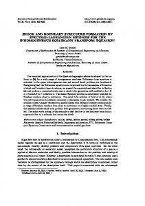
Figure 4 Dependence of the secondary instability on the electric field. a,Height of the PMMA rims as a function of the total applied electric field U/d (annealing time:18h). b,aspect ratio (height/width) of the PMMA rims as a function of the total electric field. The lines are linear fits.
Eventually,once the PS columns are formed,a secondary instability sets in. Because part of the PMMA film has been exposed to air, a lessdamped instability (with a much lower time constant) of the PMMA surface is now possible.But because the PMMA film is no longer planar, the instability is nucleated at the locations where the electrostatic pressure is highest. Because this is the case in locations of maximal PMMA layer thickness6, the destabilizing driving force is largest at the peaks of the PMMA cusps, which are adjacent to the PS columns. As a consequence, the electrostatic force leads to an increase in the PMMA cusp height,that is,the PMMA is drawn upward along the perimeter of the PS columns. The final morphology consists of PS columns coated by a layer of PMMA (Fig.1d).Because PMMA wets the silicon substrate as well as the PS–wafer interface, a thin layer of PMMA remains, covering the entire substrate. Because such thin, polymer films are unfavourable in terms of their electrostatic energy,(driving most of the PMMA into the mantle that surrounds the PS column), the equilibrium thickness of this PMMA film is given by the balance of the
free energy of PMMA on the substrate (favouring the wetting of PMMA) and the electrostatic energy. The reduction in structure size is given in terms of a volumeconservation argument.Per unit area λ2 the volumes of the primary and secondary structures are given by λ2h = CVPS and λ2H = CVPMMA, respectively,where h and H are the initial layer thicknesses as before (see Fig. 1), VPS and VPMMA are the volumes of the final structures (columns, lines per unit length λ),and C is a numerical constant,corresponding to the number of columns per unit area λ2.For the cylindrical morphology in Fig. 2, VPS = πdr2 and VPMMA = πd(R2 – r2), with r, R being the radii of the PS and composite (PS + PMMA) columns, respectively. From these equations, the reduction in lateral structure size is calculated: (R–r)/r=(1+H/h)0.5 –1.This argument is valid only if no polymer layer remains on the substrate. In our case, a laterally homogeneous PMMA layer is left, due to a lack of equilibration (that is, not all PMMA was drawn into the mantle surrounding the columns). In this case H must be replaced by Hi – Hf, where i and f refer to the initial and the final averaged PMMA film thickness, respectively. The reduction factor of (R – r)/r ≈ 0.12,derived from Fig.2c corresponds to a remaining PMMA film thickness of Hf ≈ 125 nm. The structures formed in an electric field are far from the field-free thermodynamic equilibrium. This applies to the primary as well as the secondary instability. Except for very small aspect ratios, columns are not thermodynamically stable, and are expected to decay through a Rayleigh instability in the absence of an applied electric field. A lateral coarsening of the columnar morphology is often also suppressed, in particular when the columns are not connected by a laterally homogeneous film. In addition, a PMMA layer that covers the PS–air interface is unfavourable, because PS has a slightly lower surface energy and is known to segregate to the air surface.Electric fields that are strong enough can, however, overcome these forces. With the destabilization mechanism understood, we can tailor the hierarchical structure formation in a lithographic process5. Figure 3 shows results where the planar top electrode was replaced by a topographically patterned silicon wafer (Fig. 3a, inset). Here, the variation in the plate spacing d causes a lateral variation in the electric field. Such an inhomogeneous field has two consequences. First, the capillary instability is focused towards the regions of highest electric field, that is, toward regions where the air-gap (d – (h + H)) is smallest. The liquid polymer is drawn towards the protrusions extending downward from the top plate.Second,the characteristic time constant τ associated with the capillary instability is short in regions of small airlayer thickness. τ decreases strongly with decreasing electrode spacing6 d (τ ≈ d–6 corresponding to an increase in the electric field τ ≈ E6), causing a significantly earlier onset of the instability beneath the protrusions of the patterned electrode. This leads to a replication of the 1-µm-wide lines in Fig. 3a. In Fig. 3b, a higher magnification AFM image of the transferred line pattern is shown. After disassembly of the capacitor device, a perfect replication of the master electrode is revealed, similar to the case of a single layer of polymer5. After removing the PS, PMMA structures with smaller lateral dimensions are revealed: lines 100 nm wide and 160 nm high are produced at the edges of the replicated lines. Similar to the planar electrode case, the pattern replication exhibits a hierarchic structuring process. Initially, the PS–air surface becomes unstable and the PS is drawn towards the downward protruding lines, thereby replicating the master electrode. The PS line formation produces areas with free PMMA surface, and causes a viscous deformation of the PS–PMMA–air contact line. The secondary instability of the PMMA–air interfaces causes a flow of PMMA to cover the PS lines. The height and width of the PMMA structures (and therefore their aspect ratio: height/width) are given by the electrode spacing,the lateral density of topographic features on the master wafer, and the initial film thickness of the PMMA layer. Because the PMMA is redistributed from
nature materials | VOL 2 | JANUARY 2003 | www.nature.com/naturematerials
51 © 2002 Nature Publishing Group
ARTICLES a
b
20 µm
c
20 µm
d 50
Height (nm)
40 30 20 10 0 20 µm
0.0 0.5 1.0 1.5 2.0 Lateral distance (µm)
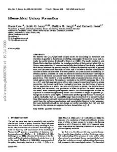
Finally, the reliability of this structure-replication technique must be emphasised.Low-magnification optical micrographs of a structured, 200 × 200 µm2 area are shown in Fig. 5. Apart from isolated defects (caused by dust), the pattern of the master electrode was reproduced with high fidelity.By dissolving the PS,a similar quality in replication by the PMMA secondary structure was found. With properly aligned electrodes, structure replication can therefore be extended to very large areas. In summary, the described novel, electric field-induced structureformation process in polymer bilayers occurs by the sequential growth of electrohydrodynamic instabilities. This results in the formation of hierarchical patterns with two independent, characteristic lateral dimensions. In particular, the secondary instability leads to structure widths that can be significantly smaller (by about a factor of 10) than the primary structure size. When combined with a topographically patterned electrode, this strategy can be used to replicate patterns of ∼100 nm, much smaller than the pattern size of the master. Two materials can be patterned in a one-step procedure, instead of a multistep process using other lithographic techniques. This approach can be extended to lateral hierarchical structures consisting of a larger number of different materials, and more than two independent lateral length scales.
2.5
Received 30 September 2002; accepted 14 November 2002; published 8 December 2002. References
Figure 5 Large-area images of replicated patterns.To illustrate the fidelity of the replication process,optical micrographs of a 200 × 200 µm2 replicated area are shown. The area consists of spherical cylinders arranged on a square lattice,with cylinders at each vertex and in the middle of the lines connecting the vertices.The image in a,taken immediately after the disassembly of the capacitor,shows a replicated film containing both PS and PMMA.After the removal of PS,an ordered array of PMMA rings remains on the substrate (b).The magnified image in c was obtained using dark-field illumination to enhance the optical contrast.In d,an AFM cross-section of one of the PMMA rims is shown.
a film into lateral structures spanning the electrodes, the width of these structures is determined by a volume conservation argument.Similar to the discussion above, (R – r)/r = (Hi – Hf)/h ≈ 0.1, where r and R correspond to the half-width of the PS and PS–PMMA composite lines, respectively. Both our experimental results and the volumeconservation argument imply that the aspect ratio of the PMMA lines can be adjusted by varying either the thickness of the initial PMMA layer or the annealing time. In practise,we found that achieving the final state (Fig.1d) occurred only after very long times (for our experimental system, equilibration was not achieved even after several days). This could be significantly reduced by decreasing the molecular weight (and thereby the viscosity) of the PMMA layer or by increasing the electric field. Figure 4 shows a linear vertical growth of PMMA structures (all annealed at an applied voltage of 50V for 18h at 170°C) as a function of the electric field.
1. Brochard-Wyart, F. & Daillant, J. Drying of solids wetted by thin liquid films. Can. J. Phys. 68, 1084–1088 (1990). 2. Reiter, G. Dewetting of thin polymer films. Phys. Rev. Lett. 68, 75–78 (1992). 3. Seemann, R., Herminghaus, S. & Jacobs, K. Gaining control of pattern formation of dewetting liquid films. J. Phys. Condens. Mat. 13, 4925–4938 (2001). 4. Herminghaus, S. Dynamical instability of thin liquid films between conducting media. Phys. Rev. Lett. 83, 2359–2361 (1999). 5. Schäffer, E., Thurn-Albrecht, T., Russell, T. P. & Steiner, U. Electrically induced structure formation and pattern transfer. Nature 403, 874–877 (2000). 6. Schäffer, E., Thurn-Albrecht, T., Russell, T. P. & Steiner, U. Electrohydrodynamic instabilities in polymer films. Europhys. Lett. 53, 518–524 (2001). 7. Lin, Z. et al. Electric field induced instabilities at liquid/liquid interfaces. J. Chem. Phys. 114, 2377–2381 (2001). 8. Schäffer, E., Harkema, S., Blossey, R. & Steiner, U. Instabilities in polymer films induced by a temperature gradient. Europhys. Lett. 60, 255–261 (2002). 9. Mönch, W. & Herminghaus, S. Elastic instability of rubber films between solid bodies. Europhys. Lett. 52, 525–531 (2001). 10. Böltau, M., Walheim, S., Mlynek, J., Krausch, G. & Steiner, U. Surface-induced structure formation of polymer blends on patterned substrates. Nature 391, 877–879 (1998). 11. Melcher, J. R. Field-Coupled Surface Waves (MIT Press, Cambridge, Massachusetts, 1963). 12. Lin, Z., Kerle, T., Russell, T. P., Schäffer, E. & Steiner, U. Electric field induced dewetting at polymer/polymer interfaces. Macromolecules 35, 6255–6262 (2002). 13. Lambooy, P., Phelan, K. C., Haugg, O. & Krausch, G. Dewetting at the liquid-liquid interface. Phys. Rev. Lett. 76, 1110–1113 (1996). 14. Wang, C., Krausch, G. & Geoghegan, M. Dewetting at a polymer-polymer interface: film thickness dependence. Langmuir 17, 6269–6274 (2001).
Acknowledgements We thank B. Maile and eXtreme Lithography for the master patterns. This work was partially funded by the Deutsche Forschungsgemeinschaft (DFG) through the Sonderforschungsbereich 513, by the Dutch Stichting voor Fundamenteel Onderzoek der Materie (FOM), by NASA under contract NAG8-694, and by the National Science Foundation-supported Materials Research Science and Engineering Center (DMR98-09365). Correspondence and requests for materials should be addressed to T.P.R. or U.S.
Competing financial interests The authors declare that they have no competing financial interests.
nature materials | VOL 2 | JANUARY 2003 | www.nature.com/naturematerials
52 © 2002 Nature Publishing Group