based on PLC (Programmable Logical Controllers) such as: index addressing; ..... to reducing the number of variables by at least 3.136 and the pace reserved.
HIERARCHICAL STRUCTURES BASED ON PLC DISTRIBUTED SYSTEMS
Luige VLADAREANU Institute of Solid Mechanics of Romanian Academy
The paper presents a deep study of advanced programming techniques of the automation system based on PLC (Programmable Logical Controllers) such as: index addressing; saving data to Flash EPROM when the power supply drops down and refreshing of status variables when the power is turned on; acquisition and digital processing of analogue signals; complex arithmetic functions; special functions for closed feedback loop adjustment PI-PID; memory allocation, word and double word processing, etc. There is presented a versatile communication network in hierarchical structure integrated through an Advant field bus as a decentralized, safety system in Advant OCS networks. There are included examples of applications for developing top technologies used in food processing industry, petrochemical industry and agriculture. In the end there is shown a hierarchical structure system for automatic management of industrial processes.
INTRODUCTION. Top technology applications and advanced technologies require transmitting a massive amount of data, larger communication, control distances and connections with other systems. Most of the complex automation systems and installations try to solve problems such as reducing the volume of cable used, assembly time, design, software programming and certainly the cost [1, 2]. Basic elements in getting these performances are: • Distributed intelligence. The use of decentralized automation technology divides up the processing work on system components their own compact processor. A controller then only defines setpoint values for these remote processors and ensures that they are correctly executed [3, 4]. The decentralized intelligent simplifies design and assembly, reduces the amount of programming work and also commissioning times. Modifications and the extensions are possible without any problem and the efficient diagnostics fault search times. • Making the connection. The connection between the controller, the input/output modules and decentralized processing modules is made via the system bus. It creates the conditions for eliminating the complex and fault-vulnerable laying of measurement and control cables, because it replaces the multitude of cable connections and a correspondingly large number of terminals, connectors etc. with a simple two-wire line which serves as the system bus. The controllers also offer the possibility of connection to current and often already existing communications buses (e.g. PDnet, ARCNET, RCOM, MODBUS) for higher-order communication. • User-friendly all round. Intensive and permanent information exchanges with the users form the basis of enhancing the system. • Clearly structured. The higher-order controller can be networked to each other for large configurations [5, 6].
Luige Vladareanu
Depending on your requirements, various networks are available for this purpose. This structure allows the user to plan, design, assemble and put into operation the autarkic system components independently of each other.
100 % 80 %
50 % 50 % 40 % 30 %
30 %
Design
Material (cable)
Assembly
Programming
30 %
Commissioning Equipment costs
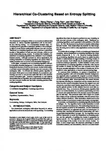
Fig.1
Studies shows that, by using smart decentralized automation systems Advant Controller 31 (AC31), one may reduce to less than 80% of cable, 50% less assembly work, 40% less programming work, 30% less design and commissioning, 30% less equipment costs (fig.1). The Advant Controller 31-S is also open to higher-level controllers and networks. It can be integrated via the Advant field bus as a decentralized, safety-orientated system in Advant OCS networks. Other standard interfaces include ARCNET, PDnet, MODBUS, Profibus, RCOM for data teletransmission or an open ASCII protocol. COMPLEX HIERARCHICAL SYSTEM The PLC automation systems provide versatile communication means (fig.2): Procontic CS31 BUS (CS31 FIELDBUS) is a fast bus which stands as basis of communication for automatic systems in the family CS31 and AC31. It links the MASTER bus and the SLAVE process modules and controls digital signals as well as analogue ones; using this kind of bus a central unit can communicate to up to 31 modules. The bus is of type RS485 on twisted pair cable, specially designed for immunity against powerful noise and for fast data transfer. The two twisted and shielded cables can provide reliable data exchange up to 500 m, and using signal repeaters this distance can be increased do 2.000 m. PLC Procontic T200 automata – distributed, are automata which allow using smart distributed technique. By connecting them to the CS31 FIELDBUS one can extend them in a decentralized system. Thus, every central unit can command up to 4 CS31 bus systems by means of a line coupler. This coupler is not part of a different project as inputs and outputs are usually controlled by the central unit. ARCNET network, is used in smart decentralized systems for fast connection of the central unit to the network. It allows to transmit the signal up to 300 m and using signal repeaters this distance can be increased do 6 km. High data exchange rate is provided by a communication speed of 2,5 MBPS. ZB20 bus is a network specially designed for Procontic T200 providing the highest data transmission rate and easy designing features. All data belonging to the central unit may be accessed using the program instructions without any further design. MODBUS (RTU), provides, due to higher level processing, possibility to connect to several wellknown automation modules, as well as to command terminals and PC stations. The coupler designed for Procontic CS31 and designed for Procontic T200, provide data exchange to a maximum rate of 19,2 KBPS and can work either as MASTER or SLAVE.
Hierarchical Structures Based on PLC Distributed Systems
RCOM, is a system dedicated to data exchange at distance. This allows sending data to standard networks as well as to radio communication systems. Due to its high flexibility RCOM provides a good response time and can be adapted to other dedicated data transmission networks. PDnet links together various distributed systems, with PC stations and other communication systems. The PDnet coupler is a configuration device, which rapidly and safely controls data transmission and is independent with respect to any automation module. As for the data exchange rate and distance PDnet has the same advantages as ARCNET.
PC
PC
PDnet RCOM MODBUS ARCNET
ZB20
07KT94
COM2
24 DI
PLC - T200
CENTRAL UNIT 16 DO
16 DC
8 AI
CS31
I/O MODULES SMART TERMINAL
COM1 U.C.
I/O
I/O
I/O
BUS
4 AO
CS31
I/O MODULES SMART TERMINAL
FIG.2 - VERSATILE COMMUNICATION NETWORK IN HIERACHICAL STRUCTURE
For a complex hierarchical system, in many applications an important and absolutely necessary feature is the possibility to connect it to other communication systems. Generally there is used MODBUS as processing standard for connection. Higher data transmission rates require PDnet because of the very easy way to mount the coupler and to process the communication program [7]. For connection to other completely different communication systems, which are closed systems (e.g. bar code reader), it is mandatory to use specific protocols. By using a communication processor and the development software one can program using C language and communicate using a given protocol. Development software performance improvement. The continuously developing automation concepts require new programming solutions to be adapted to advance technologies [8, 9]. This implies finding software “user-friendly” in matters related to programming, testing, graphic interface and commissioning of distributed automatic systems.
Luige Vladareanu
The new programming software represents a new generation with many improved features [10]: • Five programming languages for PLC: Instruction List (IL), Sequential Function Chart (SFC), Function Block Diagram (FBD), Structured Text (ST), and Ladder Diagram (LD). • The most powerful programming tools for distributed automation under Windows; it can be used to generate, test and document user programs for the programmable logic controller. • The software user interface is based on
PC COM2
SUPERVISING, MONITORING AND DATA MANAGEMENT
SAE MT-60
2 COM X4
SIGNALLING PANEL
TERMINAL DISPLAY OPERATING INTERFACE
3 07KT94
COM2
24 DI
CENTRAL UNIT 16 DO
16 DC
8 AI
COM1 CS31 FIELD BUS 4 AO
96
CENTRAL UNIT
4 x 07DC92
07DI92
07AC91
3 x 07DC91 EXECUTION LEVEL
FIG.3. EXAMPLE OF HIERARCHICAL STRUCTURE SYSTEM WITH DECENTRALIZED PLC
The Windows standard with its familiar advantages: • Pull-down menus used to choose functions • Dialog boxes containing, amongst other things, the directories of equipment, files and modules • Menu bar and graphic button bars for even simpler program generation • Debugging. This allows step-by-step editing of the automation program, including setting break points. • Offline simulation. The software package allow simulating the program run without connected hardware. This means that all instructions and commands for an external PLC, including operating errors, can be simulated. • Integrated visualization. Such visualization is elaborated offline with the aid of geometrical elements, which then change their shape or color for instance online as a function of the specific variable values. Ready-to-use pictures and graphics can be integrated. • Open system structure: • Interfaces to CAD/CAE systems • Interfaces to high-level language programming • Interfaces to data teletransmission
Hierarchical Structures Based on PLC Distributed Systems
SYSTEM FOR AUTOMATIC COMMAND OF INDUSTRIAL PROCESSES IN HIERARCHICAL STRUCTURE. In the following pages there is presented a project completed by the authors which intends to solve the issue of complex and complete automation of tyre vulcanization presses. The automation is accomplished by means of programmable logic controllers (PLCs) that manage the entire vulcanization process performing various tasks such as automatic loading of presses, vulcanization process in active cycle, automatic unloading of presses, as well as monitoring of parameters of the vulcanization. Within a communication network all PLCs of the presses are linked to a computer which has the tasks of displaying the graphical user interface of the vulcanization process for each press, monitoring of alarms and status of each press in the vulcanization cycle, and plotting graphs and diagrams of technological agents of the vulcanization process (fig.3). The PLC also controls a “mechanical arm” (manipulator) for loading/unloading of the press and replaces the classical cycle programmer KENT-TAYLOR as well as BRISTOLL recorder. The goal of the proposed project is to determine, based on research activity, the technical solution for building an automatic system for controlling tyre vulcanization processes. ADVANCED PROGRAMMING TECHNIQUES OF THE PLC AUTOMATION SYSTEM The PLC software provides a wide-ranging, integrated library from which a large number of complex function modules can be called up quickly. On-line documentation also gives you information about these modules at the press of a button. The library can be extended with individually created logic elements (CE) from function modules and instructions. In order to reduce the number of used variables, modules and, consequently, of the memory reserved for the application software, in programming the PLC system for automation of vulcanization presses there were used several types of advanced programming methods and instructions such as: RAM PLC
RAM SAE
48
MD50,02 TYPE 1 (48 PARAMS)
INDEX[MD49,08] =3(NN-1)*16 PROCESSED TYRE [MD06,08]=NN 1