rately, such as scalar replacement, register allocation, .... Each module has a separate name space. .... Reusing register names would reduce the number of.
Hierarchical Tiling for Improved Superscalar Performance Larry Carter
Computer Science and Engineering Department, University of California at San Diego, La Jolla CA 92093-0114 and San Diego Supercomputing Center, 10100 Hopkins Drive, La Jolla CA 92093-0505
Jeanne Ferrante
Computer Science and Engineering Department, University of California at San Diego, La Jolla CA 92093-0114
Susan Flynn Hummel
Polytechnic University, Brooklyn, NY 11201 and IBM T.J. Watson Research Center, Yorktown Heights, NY 10598
Abstract It takes more than a good algorithm to achieve high performance: inner-loop performance and data locality are also important. Tiling is a well-known method for parallelization and for improving data locality. However, tiling has the potential of being even more bene cial. At the nest granularity, it can be used to guide register allocation and instruction scheduling; at the coarsest level, it can help manage magnetic storage media. It also can be useful in overlapping data movement with computation, for instance by prefetching data from archival storage, disks and main memory into cache and registers, or by choreographing data movement between processors. Hierarchical tiling is a framework for applying both known tiling methods and new techniques to an expanded set of uses. It eases the burden on several compiler phases that are traditionally treated separately, such as scalar replacement, register allocation, generation of message passing calls, and storage mapping. By explicitly naming and copying data, it takes control of the mapping of data to memory and of the movement of data between processing elements and up and down the memory hierarchy.
This paper focuses on using hierarchical tiling to exploit superscalar pipelined processors. On a simple example, it improves performance by a factor of 3, achieving perfect use of the superscalar processor's pipeline. Hierarchical tiling is presented here as a method of hand-tuning performance; while outside the scope of this paper, the ideas can be incorporated into an automatic preprocessor or optimizing compiler.
1 Background Iteration-space tiling, also known as partitioning or blocking, is an important and well-known technique [JM86, GJG88, IT88, W87, RAP87, W89, HA90, L90, LRW91, RS91, WL91, WL91b, B92, KM92] that has been used both to achieve parallelism and improve locality. Both tiling and hierarchical tiling focus on very structured computations where the bulk of the execution time is spent in nested loops. Given such a loop, the iteration space is Z N , where Z represents the set of integers, and N is the depth of nesting. If the loop bounds are known, then a nite subset of Z N can be used. The Iteration Space Graph (ISG) [RS91] is a directed acyclic graph whose nodes represent the initial values and computations in the loop body, and the edges represent data dependences [PW86]1 between nodes. An example ISG is given in gure 2. Tiling partitions the iteration space into uniform tiles of a given size and shape (except at boundaries of the iteration space) that tessellate the iteration space. A tiling corresponds to an execution schedule for the ISG | the computations in one tile will be executed together on one processor, then the computations in another tile, and so on. This execution order is typically embodied in the optimized program by a new, more deeply nested set of loops. Hierarchical tiling uses an abstract machine model in which the various levels of a computer's memory hierarchy and parallelism structure are represented by di�erent levels in the model. Each level can be tiled; each tile of a higher level is further divided into subtiles for a lower level. Thus this work (like that 1 Since the ISG has a distinct node for each value produced, only true dependences need to be represented. Discarding output and anti-dependences enhances the opportunities for optimizations.
of [NJVLL93]) raises the issue of the intereaction of tiling at the di�erent levels. But whereas traditional tiling a�ects data movement implicitly by altering the order of references to memory, hierarchical tiling exercises explicit control over all data movement in the abstract machine model. This can facilitate the overlapping of data movement with computation. Section 2 outlines our approach. Section 3 introduces the example which is applied to registers and processors in section 4; the best results were obtained with further applying hierarchical tiling to the cache level, as brie y discussed in that section. Finally, section 5 has a concluding discussion.
hierarchical tiling is a PMH program. An important part of creating a hierarchical tiling is assigning storage. Storage is needed for the \surface" of the tile. Values that are on the surface of a subtiles but in the \interior" of higher-level tiles need not be assigned storage in (nor be moved in and out of) the higher-level modules. 3. The PMH program of step 2 is translated back into a \real" computer program for execution by the target computer. Because real computers don't have the simplicity of the PMH model, this involves using a variety of techniques, each tailored for a particular architectural feature.
2 Overview of Hierarchical Tiling
2.1 The computation model
Hierarchical tiling determines which operations are to be executed on which processor in which order. Furthermore it attempts to choreograph the program, that is, to direct the movement of data between processing nodes and up and down the memory hierarchy of the target computer.2 Normally, a program relies on other mechanisms for its choreography: the compiler chooses register loads and stores, the hardware chooses what lines of data to move into and out of cache, the operating system directs the movement of data between main memory and disk storage, and, depending on the system, some combination of program, system software and hardware choose the interprocessor data movement. Hierarchical tiling takes responsibility for the entire process. It proceeds as follows: 1. The processing elements, memory hierarchy, and communication capabilities of the target computer are modeled. We use the Parallel Memory Hierarchy (PMH) model [ACFS94], which is a tree of memory modules with processors at the leaves of the tree. Each module has a separate address space and all data movement is explicit. 2. The Iteration Space Graph is recursively partitioned into tiles and the tiles are scheduled for execution on memory modules in the PMH model. The root module of the PMH \executes" the entire ISG. At any non-leaf module M, a tile is \executed" by being further partitioned into subtiles, which are scheduled for execution on the child modules of M. If M is a leaf, the tile's computations are actually executed. Conceptually, the
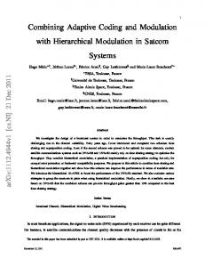
The Parallel Memory Hierarchy model represents architectural features that are crucial to achieving high performance: the multilevel memory hierarchy, the fact that data are moved in blocks, the possibility of overlapping communication with computation, and the multilevel hierarchy of parallelism. 3 Figure 1 shows the PMH tree for the IBM SP1 computer. The modules are concurrent processors that can communicate with their parents and children along the channels. Modules near the root of the PMH tree typically have more memory and wider channels than their descendents, but they are slower. Thus, they can compute loop bounds, increment index variables, and pass blocks of data to their children, but time-consuming tasks like rearranging data within blocks or performing computations on the data should be delegated to lower-level modules. The model has parameters that give the communication costs of each channel, and the memory capacity and number of children of each module. A procedure for deriving a model for given computer is given in [ACF93]. In the PMH model, all of the channels can be active at the same time, although two channels cannot simultaneously move the same block. Each module has a separate name space. Data movement along a channel is controlled by the parent module. The child can be working with other data in its memory while blocks are being transferred to or from its parent, but must not access the data in transit. We \program" the PMH using a discipline that allows us to sidestep problems such as synchronization and deadlock.
The word \attempts" is used since ultimately the other mechanismsmay overrule the choices made in hierarchicaltiling. 2
3 The PMH model may not be ideal. Further work such as [SSM89] is needed to understand which machine characteristics are important for performance.
Disks and "Global Communication" Space
Main Memory
Main Memory
Main Memory
Cache
Cache
Cache
Reg.
Reg.
Reg.
E O
E O
E O
Figure 1: PMH Model of the IBM SP1. Boxes labeled E (for even) and O (odd) are functional units that model the two-stage oating-point pipeline.
2.2 Recursive partitioning Hierarchical tiling recursively partitions the nodes of the Iteration Space Graph into tiles and schedules the tiles on modules of the PMH tree. The entire ISG is the tile for the root of the PMH tree. A module executes a tile by partitioning it into subtiles which become the tiles that are passed down to, and executed by, modules at the next level down the PMH tree. Leaf modules (i.e., the processors) actually perform the operations of the tiles they receive. The input nodes of a tile T are those nodes not in T whose values are used by nodes in T. If a tile T produces a value in a node that is used by some tile T other than T, then that node is called an output node of T. The set of input (or output) nodes of T are called its input (output) surface. Only the surface values of a tile need to be stored. As T is re ned into subtiles further down the PMH tree, temporary storage is allocated (in lower memory modules) for the new surfaces exposed. During execution, each tile T is processed in three distinct phases: 1. T's input surface is moved from the parent module P into the module C that will execute it. (Any portion of the surface that is already in C need not be moved.) 2. C executes the tile. During this time, no data of T may be moved between P and C. Thus, T must be su�ciently small that its entire surface can t in the memory of C. (C may also need memory for the surfaces of past and future tiles, as well as for new surfaces of the subtiles it creates while
executing T.) C only works on one tile at a time. 3. When the execution of T is complete, the output surface of T can be moved back up to P. P can retain some of the output surface for future use. If the surface has no uses by other modules, it needn't move up. There are many opportunities for concurrency. First, C can execute T by partitioning it into subtiles that it feeds to its children in parallel. Second, since C is fed a sequence of tiles from P, the three phases can be pipelined. The optimal size and shape of tiles at a given level depend upon the dependences of the ISG and the parameters of the modules, and con icting requirements must be balanced. Larger tiles improve the computation to communication ratio, but tiles must t in the designated modules; small tiles get everything started earlier when there are inter-tile dependences. Some guidelines for creating e�cient hierarchical tilings are: �
Surface shared by tiles executed consecutively by a module should be large. Use squat rectangles or
slabs that are \stacked" along their large surface.
�
Where parallelism is present, generate independent subtiles. If a module has c children, a good
initial guess is to partition a tile into 5c or 10c subtiles, assuming the child modules can comfortably hold tiles of that size.
�
Keep the input surface of a tile separate from its output surface. This prevents storage-related de-
pendences which would limit scheduling.
0
�
�
Swap input and output names to save storage at shared surfaces. This leads to a style of program-
ming with two tiles per loop iteration. Strive for relaxed synchronization. The abstract model may not be accurate. Leave a gap between the time when a result is available and when it is required somewhere else.
2.3 Producing a program The nal step in hierarchical tiling is converting the PMH program to an executable program. Some aspects of this are easy, for instance, message-passing primitives give explicit control over interprocessor communication. Certain language features may help, e.g. CICO directives [LCW94] guide cache choices. However, the programming languages may not provide a way to express all the desired data movement.
Programs can only indirectly specify register usage or schedule instructions. One must sometimes \trick" the compiler into producing the desired code, or, as a last resort, use assembly-language code. Other aspects of data movement may not even be under be compiler control, such as cache and page replacement.
top order within each strip). Similarly, two rectangular tiles can be executed in parallel, provided that one tile lies entirely below and to the right of the other.
3 Running Example: PDE
Although standard tiling chooses what operations will be executed in the innermost loop, it leaves the jobs of register allocation and instruction scheduling to the compiler. Our approach attempts to control these choices by the ne-grained tiling of the ISG. The advantages of the approach include:
This paper will use the SP1 and a simple doublynested loop as a running example: for I = 1 to T for J = 1 to S A(J) = C*(A(J-1) + (A(J) + A(J+1)));
This example comes from a paper by Wolf and Lam [WL91]. The explicit parentheses imposes a particular sequence of oating point operations; we do not allow algebraic reformulations for our experiments. There are nevertheless many opportunities for resequencing and overlapping the computations, leading to parallelized code with improved utilization of the processors. Following the convention of Wolf and Lam, the ISG can be pictured as a parallelogram as in gure 2. Each node of the parallelogram represents the three oating point operations described above. Each node has data dependence edges from its neighbors to the left, below, and below-left, as illustrated by the arrows (the arrows going into the bottom and left-hand nodes are for the initial data values.) Notice
Figure 2: Iteration space graph for PDE example. that if two nodes are connected by a sequence of dependence edges, then the sink node is above and to the right of the source. Therefore if two nodes lie on a line with negative slope, there is no dependence between them, and they can be executed in either order. There are many possible computation orders that respect the data dependences in the ISG. For instance, Wolf and Lam [WL91] improve cache usage on a uniprocessor by partitioning the parallelogram into vertical strips, and evaluating the strips left to right (using a bottom to
4 Registers and Functional Units
�
It is possible to get more e�cient use of registers and pipelined instruction units.
�
Nodes that are not on a tile's surface do not need to be stored in memory or reloaded into registers.
In the example PDE code, these improvements more than double the speed over the naive code, as described in this section. The RISC System/6000 processor used by the SP1 can initiate a oating point instruction each cycle, but each instruction requires two cycles to complete. To achieve maximal usage of the processor, the result of one oating-point instruction should not be used as an operand of the next instruction, though it can be used by the one after that. To model this pipeline as a PMH, two separate oating-point units are associated with each register module, as in gure 1. One of these leaf modules, even, executes the oating-point instructions that come in even-numbered cycles, while odd executes the others. We strive for a relaxed synchronization, allowing several cycles between when a result is produced by one leaf module before being used by the other, as well as between loads, uses and stores. A second feature of the processor is that loads to the oating point unit are executed by the xed-point processing unit. This is modeled conveniently in the PMH by saying the bus between cache and registers can be active simultaneously with the buses between registers and even or odd. A nal feature of the SP1's processor is that
oating-point stores actually do take a cycle of the
oating-point unit. Thus, it is desirable to reduce the number of stores. We create the hierarchical tiling starting from the bottom level of the PMH model (corresponding to the nest-granularity tiling) and work upwards. For sim-
plicity 4 we assume that even and odd each execute a single node of the ISG as an atomic (6-cycle) action. Following this view, the \memory" of the oatingpoint unit holds four values (three input and one output), each nest-granularity tile is a single node. Translating this to a conventional programming language is easy: the statement R2 = C*(R17 + (R5 + R3));
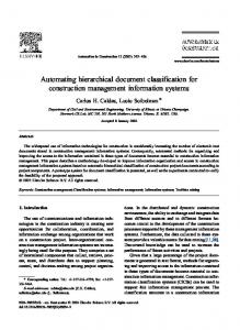
says that registers moves R17, R5 and R3 down to even (or odd), which executes the tile, and then the result is returned to register R2. Now things become less trivial. We must choose a size and shape for the tiles that are executed in registers. To enhance surface sharing, we want to use a stack of short, wide tiles as in gure 3(a).5 Suppose we use tiles that are 1 node high and K wide, for some well-chosen6 value K. Unfortunately, each point in such a tile is dependent on its left-hand neighbor, so no parallelism is possible. To keep both even and odd busy, we choose instead a tile that has two horizontal line segments as in gure 3(b). T3 T2 T1
O O O O O O O O O O O O O O O O O O O O O O O O
E E E E E E E E E E E E
a)
b)
O O O O O O O O O O O O
Figure 3: Stack of register tiles. Nodes labeled E can be executed in parallel with those labeled O.
LB
EB1
EB2
EB3
EB4
LA
EA1
EA2
EA3
EA4
OB1
OB2
OB3
OB4
EB4
OA1
OA2
OA3
OA4
Figure 4: Register tile and names for PDE example. The nodes labeled EB are executed by even, those labeled OB are executed by odd. The other labeled nodes are used as inputs in computing these nodes (see gure 2 for dependences). A more aggressive approach would be to break each node into its three component oating-poing operations. Doing this is unnecessary in the example. 5 Alternatively, we could use tall, narrow tiles and execute a horizontal sequence of tiles. Both work. 6 Making K large is desirable to amortize the store operation over 3K oating point operations. However, the surface of a 1 � K tile is 2K + 2, which limits K to 15 since there are 32 registers. 4
Figure 4 shows the names in registers' address space. Notice that (with one exception) the register names are all distinct. This is partly necessary and partly convenience. For instance, the result labeled EB2 could not be stored in register EA2, since the value in EA2 still needs to be used in computing EB3. However, it is possible to store EB2's result in register EA1. Reusing register names would reduce the number of registers needed (allowing for larger tiles) but it creates (not insurmountable) di�culties at the next level up the PMH tree. The one exception to having distinct register names is that EB4 is used twice. This creates an output dependence between two nodes in the tile | OB1 must be computed before the upper EB4. Since OB1 is the rst node to be executed by odd and EB4 is the last for even, this satis es our desire for relaxed choreography. Other than that one dependence, the operation of even and odd are completely independent. Finally, we must arrange to pass a vertical stack of these tiles down from cache to registers. This is where our choice of register names is convenient | we can \ping-pong" the input and output surface names by swapping all the A's for B's in the register names. After two tiles are passed, we end up in the same state as when we started. This allows us to translate the PMH choreography into the conventional program shown in gure 5. for i=1 to TileHeight-2 by 2 { LB=LEFT(i+1); /* Start of tile i */ EB1=C*(LB +( LA+EA1)); OB1=C*(EA4+(EB4+OA1)); EB2=C*(EB1+(EA1+EA2)); OB2=C*(OB1+(OA1+OA2)); EB3=C*(EB2+(EA2+EA3)); OB3=C*(OB2+(OA2+OA3)); EB4=C*(EB3+(EA3+EA4)); OB4=C*(OB3+(OA3+OA4)); RIGHT(i)=OB4; LA=LEFT(i+2); /* Start of tile i+1 */ EA1=C*(LA +( LB+EB1)); OA1=C*(EB4+(EA4+OB1)); EA2=C*(EA1+(EB1+EB2)); OA2=C*(OA1+(OB1+OB2)); EA3=C*(EA2+(EB2+EB3)); OA3=C*(OA2+(OB2+OB3)); EA4=C*(EA3+(EB3+EB4)); OA4=C*(OA3+(OB3+OB4)); RIGHT(i+1)=OA4; }
Figure 5: Inner loop code produced by hierarchical tiling of registers and processors for PDE example. Figure 6 shows the number of cycles per node for the original code,7 the same code compiled using the 7 All compilations in this paper used the AIX XL Fortran Compiler, Version 3.2.0, with the -O3 optimization level.
-Pk preprocessor,8 and code of gure 5 produced by hierarchical tiling. Original Code 9.0 Using -Pk preprocessor 4.75 With Reg+FMA Tiling 3.125
Figure 6: Cycles per Node for inner loop. The relatively slow performance of the original code is caused in part by the fact that each oating-point operation is dependent on the previous one. If this were the only problem, however, the code would take only 6 cycles. There appears to be an additional 3cycle delay caused by a hardware interlock between the store in one iteration and the loads of the next. The unrolled code produce by the -Pk preprocessor allows for better use of the oating-point pipe. If the usage were perfect, the code would take four cycles per node (one for each of the three operations and one for the store). However, there appears to be three additional cycles for every four nodes due to various pipeline delays. The main advantage of the code produced by hierarchical tiling is that instead of storing the value of each node of the ISG, only one in eight (the rightmost node of each tile) requires storing in cache. The code of gure 5 requires a minimum of 50 cycles (48 operations plus two stores) to compute 16 nodes. The fact that it actually runs in 50 cycles shows the second advantage of hierarchical tiling { it allowed perfect use of the oating point pipeline and of the overlapped loads provided by the hardware. The inner loop code produced by hierarchical tiling computes an 8-node wide vertical strip of the Iteration Space Graph. We incorporated it into a program (called \Reg+FMA") that computes the entire ISG. The program is straightforward but messy due to the ragged-edged, sometimes-triangular border pieces. The resulting code has a substantial overhead for small problem sizes. Nevertheless, one might hope that as the problem size increased, the performance would approach the 3.125 cycle/node speed of the inner loop. The actual timings, shown in gure 7, show that performance of Reg+FMA gets worse when the problem size exceeds 4000. The same e�ect can be seen more clearly in the original code in gure 7, where cycles/node increases from about 9 to above 10 when 8 -Pk -Wp,-optimize=5,-scalaropt=3,-roundoff=3
speci ed. This mainly unrolled the loop four times.
was
the problem size exceeds 4000. The problem is cache misses. The cache on a processor of the SP1 holds 4096 eight-byte oating-point numbers. S=T= Original (with -Pk) CacheOnly (with -Pk) Reg+FMA All
2000 4000 6000 8000 10000 12000 9.04 9.09 10.22 10.24 10.24 10.25 4.65 4.67 5.49 5.49 5.49 5.49 9.20 9.20 9.20 9.20 9.20 9.21 5.31 5.31 5.31 5.31 5.31 5.31 3.33 3.30 3.37 3.41 3.42 3.43 3.37 3.29 3.26 3.25 3.24 3.23
Figure 7: Performance (in Cycles/Node) on 1 SP1 processor. Standard tiling at the cache level only, which does not make particularly good use of the processor, was applied in the program labeled \CacheOnly" in gure 7. The at performance curve indicates that cache misses have been successfully amortized against a large block of computation, but the overall performance is lacking. The program labeled \All" in gure 7 is blocked for cache, registers and the oating point unit by choosing tiles at the cache level of size 800 high and 64 wide9 , each consisting of columns of register tiles. The gure shows that at large problem sizes, the \All" code produced by hierarchical tiling runs in 32% of time required by the original code; 61% of time of best code developed using competitive techniques.
5 Discussion and Future Work Several aspects of hierarchical tiling merit more discussion. First is the use of an explicit model of the target architecture. The model must include the capacities of the various storage mechanisms. For problems where memory references are less local, information about cache and TLB block sizes and associativity might be needed. Second is the need to translate from a program in the model to a conventional program using ad hoc methods. Increased programmer control over prefetching would make this task easier. The problem sizes we considered did not require tiling for levels above cache, such as memory and disk. By choosing a larger problem size, we could have equally well demonstrated the use of hierarchical tiling 9
The results would be very similar for other parameters.
at these levels. Another paper [CFH95] carries the example to the distributed-memory parallelism level. A distinguishing feature of hierarchical tiling is that memory for tile surfaces is only assigned at levels where it is needed, and can be reassigned after use. Traditional tiling methods don't as conveniently allow data to be copied and rearranged, and so may not achieve as good spatial locality. The question arises whether optimizations such as storage assignment and scalar replacement shouldn't be solely the responsibility of independent, generalpurpose compiler phases. The example of this paper shows that the goal-directed approach of hierarchical tiling performed better than the state-of-the-art IBM XLF compiler. Future work includes developing an explicit hierarchical tiling language and incorporating it into existing tools, such as compilers. We also plan to investigate the dynamic scheduling of tiles.
Acknowledgments We thank Bowen Alpern for helping to formulate the concepts behind hierarchical tiling.
References [ACFS94] Alpern, B., L. Carter, E. Feig, and T. Selker, \The Uniform Memory Hierarchy Model of Computation," Algorithmica, June 1994. [ACF93] B. Alpern, L. Carter and J. Ferrante, \Modeling Parallel Computers as Memory Hierarchies," Proceedings, Programming Models for Massively Parallel Computers (September, 1993). [B92] Banerjee, U., \Unimodular Transformations of Double Loops", in Advances in Languages and Compilers for Prallel Processing , A. Nicolau and D. Padua, editors, MIT Press, 1992. [CFH95] Carter, L., J. Ferrante and S. Flynn Hummel, \Ef cient Parallelism via Hierarchical Tiling," Proc. of SIAM Conference on Parallel Processing for Scienti c Computing, (February, 1995). [GJG88] Gannon, D., W. Jalby and K. Gallivan, \Strategies for Cache and Local Memory Management by Global Program Transformation," Journal of Parallel and Distributed Computing, Vol. 5, No. 5, October 1988, pp. 587-616. [HA90] Hudak, D. E. and S. G. Abraham, \Compiler Techniques for Data Partitioning of Sequentially Iterated Parallel Loops," IEEE Transactions on Parallel and Distributed Systems, Vol. 2 No. 3, July, 1991, pp. 318-328. [IT88] Irigoin, F. and R. Triolet, \Supernode Partitioning," Proc. 15th ACM Symp. on Principles of Programming Languages, January 1988, pp. 319-328.
[JM86] Jalby, W. and U. Meier, \Optimizing Matrix Operations on a Parallel Multiprocessor with a Hierarchical Memory System," Proc. International Conference on Parallel Processing, August 1986, pp. 429-432. [KM92] Kennedy, K. and K. S. Mc Kinley, \Optimizingfor Paralelism and Data Locality," Proc. International Conference on Supercomputing, July 1992, pp. 323-334. [LRW91] Lam, M, E. Rothberg, and M. Wolf, \The Cache Performance and Optimization of Blocked Algorithms," Proc. ASPLOS, April 1991, pp. 63-74. [LCW94] Larus, J. R., S. Chandra and D.A. Wood, \CICO: A Practical Shared-Memory Programming Performance Model", in Portability and Performance for Parallel Processing, A. Hey and J. Ferrante editors, John Wiley and Sons, 1994. [L90] Lee, F. F., \Partitioningof Regular Computationon Multiprocessor Systems," Journal of Parallel and Distributed Computing, Vol. 9, 1990, pp. 312-317. [NJVLL93] Navarro, J. J., A. Juan, M. Valero, J. M. Llaberia, and T. Lang, \Multilevel Orthogonal Blocking for Dense Linear Algebra Computations," IEEE Technical Committee on Computer Architecture Newsletter, Fall 1993, pp. 10-14. [PW86] Padua, D. A. and M. J. Wolfe, \Advanced Compiler Optimizations for Supercomputers," CACM, December, 1986, pp. 1184-1201. [RS91] Ramanujam, J. and P. Sadayappan, \Tiling Multidimensional Iteration Spaces for Nonshared Memory Machines," Proceedings of Supercomputing, November, 1991, pp. 111-120. [RAP87] Reed, D. A., L. M. Adams and M. L. Patrick, \Stencil and Problem Partitionings: Their In uence on the Performance of Multiple Processor Systems," IEEE Transactions on Computers, July, 1987, pp. 845-858. [SSM89] Saavedra-Barrera, R. H., A. J. Smith, and E. Miya, \Machine Characterization Based on an Abstract HighLevel Language Machine," IEEE Transactions on Computers, December, 1989, pp. 1659-1679 [WL91] Wolf, M. E. and M. S. Lam, \A Data Locality Optimizing Algorithm," Proceedings of the ACM SIGPLAN Conference on Programming Language Design and Implementation, June, 1991, pp. 30-44. [WL91b] Wolf, M. E. and M. S. Lam, \A Loop Transformation Theory and an Algorithm to Maximize Parallelism," IEEE Transactions on Parallel and Distributed Systems, Vol. 2, No. 4, October, 1991, pp. 452-471. [W87] Wolfe, M., \Iteration Space Tiling for Memory Hierarchies," Parallel Processing for Scienti c Computing, G. Rodrigue (Ed), SIAM 1987, pp. 357-361. [W89] Wolfe, M., \More Iteration Space Tiling ," Proceedings of Supercomputing, November, 1989, pp. 655-664.