and E. E. Jones. Snndin National. Laboratories,. Albuquerque,. NM 87185 ..... provided by Daryl Dew and. John Leija is also thankfully acknowledged. This work.
© 1989 IEEE. Personal use of this material is permitted. However, permission to reprint/republish this material for advertising or promotional purposes or for creating new collective works for resale or redistribution to servers or lists, or to reuse any copyrighted component of this work in other works must be obtained from the IEEE.
HIGH BRIGHTNESS IMMERSED SOURCE INJECTOR CHARACTERIZATION C. A. Frost, Snndin
J. J. National
W. Poukey, G. T. Leifeste, M. Jojola, and E. E. Jones Laboratories, Albuquerque,
D. E. Hasti, NM
87185
ABSTRACT RADL.AC II is a high current linear induction The beam is produced in A accelorntor for electrons. We report the field-immersed foilless diode injector. first time-resolved characterization of a similar highbrightness immersed diode source using a time-gated, The experiments were 2-D x-ray imaging technique. performed on the 4.MeV IBEX accelerator and produced currents exceeding 40 li4 in a 6.mm radius, thin annular benln with n measured thermal transverse velocity For currents of 30 kA, even brighter ...~-~~-O. lc. At lower currents, beaIls with 0 =0.07 were ohtained. t)ent-s as smat 1 as 2 mm in radius were produced with R smn:ler cathode tip. In all cases, the measured 1paramctzrs wcrp consistent with 2-D PIC simulations. 'I'lli- experimental results will be discussed and compared to theory ;xlld simulations INTRODUCTION
IBEX
60cm-r-52
cm-1
6.4
“w” RADIUS STAINLESS STEEL CATHODE
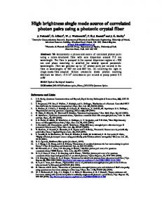
1.
Schematic immersed
of IBEX high brightness foilless diode source.
field
EXPERIMENTAL RESULTS A thin annular beam was generated as seen in Fig. 2 for the optimized case of 2.2 Tesln with a 6.3-mm I-ndius cathode and 2.0-cm A-K gap. The six plots result from scans through x-ray frames with a real time-separation of 5 ns. Figure 3 is the result of azimuthal averaging throu&h the .same data. In this form it can be seen that the annular beam radius and thickness do not vary significantly during the diode voltage pulse. An analysis of Larmor orbits as described in Ref. 6 shows that B can be computed from 1. the beam annular width w in centimeters by pl=(wn)B/(3.4 y) where a is the annular thickness of the cnthode tip in centimeters and B is in kilogauss. This analysis implies B =0.@7 for the optimized case of Figs. 2 and 3 whit l! produces n measured current of 30 kA with a mean radius of 6 mm. Again using the metllod 2 , of I/(xcb) of Ref. 6. we compute a beam brightness, 3x10."+ and 5x10+2 A/(rad-cm)2 for the magnetized and rstracted beam. respectively, where cb is the
I $COnlCnl ~~
APPARATUS Figure 1 shows the IBEX field-immersed foilless Six-inch diameter pancake diode source schematically. coils Were used to provide a uniform solenoidal pulsed magnetic B, field in the region of the annular The B, field could be stainless steel cathode tip. The cathode radius and A-K gap varied up to >2 Tesla. spacing were also varied to optimize beam current and emittance. The diode voltage was monitored with a D-dot monitor and Rogowski coils were used to measure the A metallic beam current generated by the source. plate or tantalum s-ray converter wzs used to witwss ilvnge the heam at various distances froln the cathode The beam was characterized by tip for analysis. i.nnginz the x-ray converter with a time-gated, x-ray The framing camera with 5.ns time resolution. intensified images were recorded on Polaroid film. Which 1v‘a.s scanned to provide beam intensity cont"urs.
DIODE
r-
Fig.
The upgrade oE RADIAC II t" the 40-kA level imposes sf~cr? requirements on the injector. The fieldimmfrscd diode source, which produces an annular bear geolnetry , was chosen for KADIAC because it allows !:eller:it;on of higher currents than shielded s0urces.l 111 order to obtain the s:nnll equilibrium radius :hnt is 1 c~(l~lired for atmospheric pressure bean propagation cxppriments, n high brightness, (low transverse This is because the momentum) source is essential. l>ca:l- equilibrium radius in air is proportional to the Emitt;ince (including rotation) and the square root of In one the ratio of Alfven current t" net current. 2 which used a 10 Tesla solenoidal previous experiment, an ultra-high brightness beam was generated in field, th? field, but could not be extracted due to high In another canonical angular momentum, Pg. expc:-imrnt, 3 It was dcmorlstrated that the immersed diode s"~:rcc could generate a beam of reasonable witta:lce, which could be extracted, but optimization nf bcx;lm hrightncss or time-resolved measurements of l)v;lm witrance were not attempted. Cur recent experiments on the 4-MeV IBEX operation of an immersed zccclern:"r4 have demonstrated diode source at currents and brightness greater than A unique :hc KADIAC-II upgrade requirements. the &frame gated x-ray camera, 5 was used ilnstrument. ';" study time-resolved beam generation in the source on n nanosecond time scale.
IMMERSED
Y
. ICO"SC.' i!-jyJ
t,=ons
~~
t=5ns
2.
CH2669-0/89/0000-1456$01.0@~1989
t-ions 1 Ic"-IcrI !!r
t=20ns
X-ray framing data 5-ns frame spacing.
IEEE
i
I ECO"lCrnl y+J
t;15ns Fig.
i$JJ
c
x ,COn,ini
. IcOrlLnl
for
Y
2.2-Tesln
t=zscs field
PAC 1989
with
r R a.00
Fig.
3.
Current nveragi*g
density radial profile of x-ray frame data
Fig.
from angular for 2.2 Tesla.
5.
scon(cml 0.34
0.17
Current density radial profile integrated x-ray pinhole data radius cathode with 2.2-Tesla
rormnlized beam emittnnce. The extracted brightness i;hich is of interest for beam propagation studies is :nuch higher than the requirement for RADLAC-II beam propagation experiments. Reducing the 6, field to 1.5 Tesla caused a considerable increase in the tran.sverse velocity. The 6-frame x-ray camera revealed the presence of radial oscillations 5 cm beyond the cathode tip as shown in Fig. 4. Measurements at 50 cm beyond the tip showed a Fhnse mixed beam with the radial oscillations converted t 0 tcJlnperature
r g
Fig.
0.51
6.
0.00
Current radius
0.12
scanlcml 0.24
from time for 3.2-mm field..
0.36
density radial profile for solid cathode with 2.2-Tesla
1.6-mm field
COMPARISON TO SIMJJIATIONS
Fig.
4
Current density radial profile field showing radial oscillations.
for
1.5-Tesla
To produce even higher brightness, experiments were A 3.2-mm socducted with very small cathode tips. radius tip with a :-cm AK gap and 2.2 Tesla produced a ILkA nnnulnr beam with 3-mm radius and a thermal Figure 5 displays a slice through the time ,lj=O.l. ir:tegrated s-ray pinhole image produced by this beam ,,-ittl the tantalum converter SO cm beyond the cathode. The sinnllest cathode tip studied was a 1.6-mm radius For this configuration the solid stainless steel rod. Larmor orbits were comparable to the beam size and a veil smoothed Bennett-like 12-U beam with a 2-mm For the smaller radius was produced as seen in Fig. 6. tips. the extracted beam brightness is two orders of magllitude higher than the RADLAC requirements. Production of higher currents was also studied. With the 6.3-mm radius cathode, a peak current of 39 kA was obtained for a l.O-cm AK gap at 2.4 with /?1=0.12, By increasing the cathode radius to 9.5 mm, T e s 13 ccIrr