TFB Pump Combiner. (HR) Fiber ..... The source used was a combination of multimode pumps spliced to a 32x1 TFB [8] allowing end pump coupling in the ...
High core & cladding isolation termination for high power lasers and amplifiers Alexandre Wetter, Mathieu Faucher, Benoit Sévigny, Nelson Vachon ITF Laboratories, 400 Montpellier, Montreal, Québec, H4N 2G7, Canada; ABSTRACT As overall power increases in fiber lasers and amplifiers, the amount of optical power which must be dealt with in order to obtain high core to core and core to cladding isolation also increases. This unwanted light can represent hundreds of watts and must be managed adequately. By combining a proper termination (end cap) design and cladding stripping techniques it is possible to obtain a robust output beam delivery component. The cladding stripping techniques are inspired by previous work done on high power cladding strippers. All measurement presented here are done with a flat end cap. Both core to core and core to cladding isolation will be better with an angled end cap. A core-to-core isolation of over 25dB was measured, while core to cladding was over 30dB. Power handling was characterized by the capability of the device to handle optical power loss, rather than transmitted power. The component dissipated over 50 watts of optical power due to isolation. The above results show that understanding the mechanisms of optical loss for forward and backward propagating light in a end cap and the heat load that these losses generate is the key to deliver kilowatts of optical power and protect the integrity of the system. Keywords: High power, end cap, packaging, cladding strippers, fiber laser, optical engines, termination
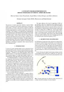
1. INTRODUCTION Fiber lasers and amplifiers are used in a growing number of applications. They have received great attention due to their ability to provide high wall-plug efficiency and excellent beam quality even at high power levels [1-2]. As fiber lasers mature towards commercial deployment, an intense focus on their reliability and that of their components is required. Reliability demonstrations are made at increasingly higher power levels. Output powers in the multi-kilowatt range have been reported, using either discrete bulk components [4,5], or all fiber components such as tapered fused bundle (TFB) [6,7] for coupling in and out of the fiber gain medium. Both all-fiber lasers and amplifiers are assemblies of individual components spliced together, as shown in figure 1. A typical laser/amplifier is composed of a tapered fused bundle (TFB) pump & signal combiner to launch pump into the cladding and signal into the core (for an amplifier) of a double clad gain fiber. For a laser configuration, a high reflector and an output coupler (low reflector) fiber Bragg Gratings are inserted in this cavity. Finally, an all-fiber termination is spliced at the output allowing for beam expansion and safe beam delivery. (HR) Fiber Bragg Grating
(OC) Fiber Bragg Grating
6-'-lxl TFB Pump Combiner
Yb dope gain LMA fiber Ox MM Pumps 105-1 25 N.A.=0.22 1 signal fiber
END CAP OUTPUT
Relay fiber 2Oum core 0.06 NA DCF fiber
10-125 NA.=0.08
Figure 1. Example of simple fiber laser/amplifier design. An all-fiber 6+1x1 TFB is spliced to a 20-400 Yb doped DCF gain fiber. The Bragg grating acts as high reflector (HR) and output couplers (OC) for a laser configuration. An all-fiber end cap at the output allows beam expansion for safe beam delivery. Fiber Lasers VI: Technology, Systems, and Applications, edited by Denis V. Gapontsev, Dahv A. Kliner, Jay W. Dawson, Kanishka Tankala, Proc. of SPIE Vol. 7195, 719521 © 2009 SPIE · CCC code: 0277-786X/09/$18 · doi: 10.1117/12.806923 Proc. of SPIE Vol. 7195 719521-1
Many undesired phenomenons will occur when the optical beam leaves the all glass optical engine. Some of these phenomenon’s, such as unwanted back reflections, will lead to stray light amplification that decrease the effective gain in the cavity. Additionally, uncontrolled high peak power pulses of coherent signal light can be re-injected in the cavity and damage the optical engines and there pumps. In order to increase overall reliability of fiber laser and amplifiers, adequate terminations are needed. These terminations (end cap) must provide high core-to-core and core to cladding isolation while ensuring proper beam quality. The core-to-core isolation is provided by the end cap design and the core to cladding isolation is provided by the integrated cladding stripper [3]. In this work, characterization of the signal light exiting the end cap and light being reflected back in towards the all glass optical engine is disused. Temperature rise of the package due to re-injected light in high power operating conditions is studied and demonstrated. This paper is structured as follows. In section 2, a brief presentation of different end cap designs is given. In section 3, we will discuses the characteristics that high power end cap must provides and present typical performances. Finally in section 4 we will explain how the unwanted light resulting from the high isolation is managed and discuss performances at high power.
2. DIFFERENT END CAP DESIGNS In figure 2, we illustrate the different areas where core and cladding light travel in a standards end cap design. As core light leaves the output fiber and enters the all glass end cap, the unguided beam diverges without interfering with the sides of the end cap (clipping). At the output face, a portion is reflected back. When traveling back, the angle of the beam increases before re-entering the output fiber. Most of this light will not couple back into the core, since the reflected beam diverges further on the way back to the core.
SPLICE OUTPUT FIBER TO ALL GLASS END CAP
ALL GLASS END CAP
CORE LIGHT DIVERGING IN
THE ALL GLASS END CAP
PROCESS RE-INJECTED LIGHT
EXH1NG CORE LIGHT
CORE LIGHT BEING RE-INJECTED
IN THE SYSTEM NA INCREASESI MOST OF THE BACK R[FLEC11ON IS REINJECTED IN THE CLADDING
Figure 2 Illustration of a standard end cap design and different areas where core and cladding light travel.
Proc. of SPIE Vol. 7195 719521-2
In high power applications, this light, which is not re-injected into the core, needs to be stripped to avoid to be guided into the cladding, and return in the optical engine. This is what we call core to cladding isolation. In an optical engine (fiber amplifier or laser) the proportion of light that must be managed due to Fresnel reflection depends mainly on two things: the angle at which is polished the end cap and the presence of an anti-reflection coating (AR coating). In the table below, we present 3 different standard end cap designs without any cladding stripping features. For each design we present, the theoretical total back reflection, the portion of this reflected light that will couple back into the core and the complementary portion that will end up in the cladding. Core light only, NO integrated cladding stripper 1mm end cap design spliced to a 20/400 0.06/0.46 DCF relay fiber
Total back reflection
Portion re-injected in the core (core to core isolation LP01)
Portion re-injected in the cladding (cladding isolation)
4%
37dB
16dB
4%
~60dB
~20dB
0.2%
50dB
30dB
Flat
Angled (EX: 8°)
Flat + AR coating
Table 1. Three different end cap design are illustrated. Theoretical reflections, core-to core and core-to cladding isolation are given for each design.
In all three designs shown above, the core-to-core isolation is acceptable while the core-to-cladding isolation is poor. In high power application, this cladding light must be stripped and managed properly in order to maintain optimal operation conditions and integrity of the optical engine.
3. IMPORTANT CHARACTERISTICS THAT END CAP MUST PROVIDE When designing an end cap, the following characteristics must be optimized: 1-Robustness do to high intensity 2- Preservation of beam quality 3-High core to core isolation 4- High core to cladding isolation. By combining a proper end cap design, a cladding stripper and proper packaging techniques, it is possible to achieve interesting result regarding all these important characteristics even in high power applications. As short explanation for each of these characteristics and some examples of the method used to quantify are given. 1-Robustness to high intensity: As the laser light exits the fiber it travels thru the all glass cylinder (end cap) and starts diverging. When reaching the glass air interface, the density is reduced. This allows to safely deliver the bean without exceeding the damage threshold of the glass (the glass-air damage threshold is 1E9 W/cm2 in CW regime and the bulk damage threshold is 40 J/cm2 @1ns in pulse regime). Figure 3 illustrates two dimensions of 3 dimensional model that is used to optimize the end cap design. The model must take into account core and
Proc. of SPIE Vol. 7195 719521-3
cladding diameter of the output fiber, numerical aperture and operating wavelength. The length of the end cap, which corresponds to the distance upon which the light diverges, is the calculated length to respect the following guideline: First, the maximum peak intensity for a given mode field diameter must be 10 times smaller then the damage threshold. Secondly, the geometrical shape of the end cap must be design to avoid clipping. Figure 4 shows the air damage threshold limit for CW light in an optical fiber against mode field diameter. This curve is base on a theoretical value of 10W/um2. We use a 10x safety factor on this maximum power to establish a safety limit for long-term operation. For a 10um 0.08NA single mode delivery fiber, the end cap is not mandatory at 150W of output power but reducing power density prevents dust attraction from the high intensity electrical field at the end facet. Since the end cap length is fixed, the divergence of the beam is higher for small MFD creating a bigger beam size at the end cap end and increasing the maximum power before reaching the air damage limit. This explains why the end cap maximum power handling decreased when you increase your MFD. However the actual design will be limited by the packaging power handling well before reaching the limit show on this graph.
Figure 3. Two dimensions illustration of a 3 dimensional model, which is used to optimize the end cap design.
Glass-air damage threshold (10W/urn2) 1000000.0
100000.0 (0
0
0 E
1000.0
E
x 100.0 Maximum P wer
Safely limit Ox Maximum Pwer after end cap with sa ty limit 10.0
50
10.0
15.0
20.0
25.0
30.0
35.0
40.0
45.0
500
Fiber Fundamental mode MFD (urn)
Figure 4. Air damage threshold curve with safety factor vs. mode field diameter of laser output fiber and end cap.
2- Preservation of optical properties of the beam: In many applications, beam quality is an important characteristic that requires a certain level of attention. For example, close to Gaussian beam quality (M^2