Proceedings of the 40th European Microwave Conference
DMS harmonic termination load network for high efficiency power amplifier applications Girdhari Chaudhary#1, Yongchae Jeong#2, Jongsik Lim*3, Chul Dong Kim**4, Dongsu Kim***5, Jun-Chul Kim***6, and Jong-Chul Park***7 #
Department of Information and Communication Engineering, Chonbuk National University 664-14, Jeonju, 561-756, Republic of Korea 1
[email protected]
*
Soonchunhyang University, Asan, Choongnam, Republic of Korea ** Sewon Teletech, Inc., Anyang, Gyeonggi, Republic of Korea *** System Packaging Research Center, Korea Electronics Technology Institute, Seongnam, Gyeonggi, Republic of Korea Abstract— In this paper, a harmonic termination load network using a defected microstrip structure (DMS) for a high efficiency power amplifier is proposed and compared with a dumb-bell shaped defected ground structure (DGS) harmonic termination load network. The proposed structure is designed for a wideband code division multiple access (WCMDA) down-link applications operating at frequency of 2.11~2.17 GHz. From the experiment, the attenuation of the DMS for the harmonic frequency (4.22~6.51 GHz) is more than 27 dB. Comparing the defected area, the DMS occupies a quarter of the DGS defected area. The DMS has caused less electromagnetic interference (EMI) noise than the DGS due to no defected area in a ground plane. The ground problem of DGS can be overcome by using DMS. Index Terms — Defected microstrip structure (DMS), defected ground structure (DGS), power amplifier.
I. INTRODUCTION As an expansion of wireless communication service systems as well as the recent interest on efficient energy consumption, demands of highly efficient RF devices are increasing day by day. Since the power amplifier (PA) consumes most of the DC power in RF front ends [1], a longer battery life is one of today’s critical design goals. Thus it is necessary to enhance the efficiency of the PA. For higher efficiency, various modes of operation of the power amplifier such as class-F and class-E have been proposed. For the high efficiency, the class-E and the class-F amplifiers are one of the promising solutions due to its simpler structure. In general, the efficiency of the class-E or class-F amplifier can be improved by suppressing the harmonics by using a proper load network [2]. In practice, it is difficult to control all the harmonics simultaneously. Therefore, in general only second and third harmonics are suppressed typically to get higher efficiencies of the PA. The DGS is realized by etching the specific patterns such as dumb-bell shape, spiral shape etc in the ground plane which provides the band rejection frequency characteristics due to increasing inductance of transmission line [3]. These band rejection characteristics have been applied to various microwave circuits such as the power dividers, filters, PAs, and planar antennas, etc. The band rejection characteristics of
978-2-87487-016-3 © 2010 EuMA
the DGS can be applied for suppressing the harmonics for the high efficiency PA [3]. The advantages of the DGS described by the previous researchers are: (a) it is easy to extract the equivalent circuit model, (b) it is easily applied to RF/microwave circuits to reduce size or improve performances, and (c) a high impedance transmission line can be obtained by using the DGS structure [4]-[6]. However, the DGS have some drawbacks. In the high frequency applications, the radiation in the etched pattern area of the microstrip transmission line using the DGS is source of catastrophic errors in system performance and measurement procedures. When the DGS is applied for microwave circuits, a problem of EMI should be considered because of a leakage through the ground plane The other main drawback of the DGS is that pattern of the DGS directly contact the ground surface when a DGS circuit is inserted into a metal housing. In other words, if the bottom plane of the microstrip line having DGS patterns meets the bottom surface of metal housing, the advantages of DGS effects would disappear. The same band rejection characteristic like the DGS can be obtained by etching on the signal strip, called DMS [7]-[8]. In case of the DMS, the defected cell is etched on top conductor (signal), so there is no leakage through ground plane. Thus, the drawbacks of DGS can be overcome by adopting the DMS structure. The reductions in the defected area in ground plane of the DGS by using the DMS and the elimination of the problem of metal housing of the DGS are the advantages of DMS over the DGS. In this paper, the harmonic termination load network for the high efficiency PA is designed using the T-type DMS for WCMDA base station down-link applications operating at the frequency of 2.11~2.17 GHz and compared with the dumbbell shaped DGS harmonic termination load network. The reflection and the band rejection characteristic of the proposed harmonic termination load network are almost similar with the dumb-bell shaped DGS harmonic termination load network.
946
28-30 September 2010, Paris, France
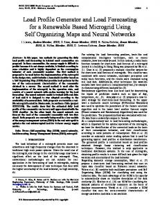
II. DEFECTED MICROSTRIP STRUCTURE Fig. 1 shows the basic pattern shape and equivalent circuit of the DGS and the DMS, respectively. In the DMS, it is called T-cell; there is no etching on the ground plane such as in the DGS. The DMS is made by etching uniform or nonuniform slot over the signal strip and etching the very small slit perpendicular to the main slot. The DMS disturbs the current distribution on the strip and thus giving modified microstrip line with certain band stop and slow-wave characteristics. As well as the DGS, the DMS increases the electrical length of microstrip line due to increase in the equivalent inductance. With this increase in electrical length, it can be applied in reduction of the size of microwave circuits such as microwave filters, power dividers, PAs, etc. The DMS can be modeled as like DGS by a parallel LC circuit connected in series with a transmission line [4], [7]-[8]. The elements values of L and C of equivalent circuit of the DMS and the DGS are calculated from Electromagnetic (EM) simulation using the following equation [4], [7]-[8].
ωc , 2 Z 0 (ω02 − ωc2 ) Z0, ω c and ω0 are
C= where
L=
1 ω02C
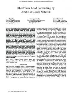
A. The DGS harmonics termination load network Fig. 2 (a) shows the DGS harmonics termination load network. For comparing with the DMS, two units of dumbbell shaped DGS are used. In this case, width of the DGS is large enough as compared to the microstrip length to avoid any parasitic behaviour of self-capacitance per unit length of the line, to get band stop at lower frequency. The physical parameters for dumbbell shaped DGS is shown in Fig. 2(a). B. The DMS harmonics termination load network Fig. 2 (b) shows the proposed DMS harmonics termination load network. The two units of T-shaped DMS are used in this work. The physical dimensions of DMS structure is shown in Fig. 2(b). The total defected area of the DMS unit cell is approximately a quarter of the DGS defected area which causes the EMI problems.
(1)
the characteristic impedance, 3 dB
cutoff angular frequency and resonance angular frequency taken from S21 graph of EM simulation, respectively. (a) 14.2 1.24 2.38 4.5
0.7 0.4
14.9 36
(a)
(b) Fig. 2. EM-Simulation layout of: (a) DGS (b) DMS harmonics termination load network. The units of physical dimensions are in mm
(b) Fig. 1. Basic layout of : (a) defected ground structure and its equivalent circuit (b) defected microstrip structure and its equivalent circuit.
III. DGS AND DMS HARMONICS TERMINATION LOAD NETWORK In the various high efficiency PAs such as the class-E, class-F, the quarter-wavelength transmission lines are used to reject the harmonics [2] but these can suppress only specific harmonic components. By employing the DGS or the DMS, the required harmonics can be suppressed by selecting the appropriate slot length tuned to specific harmonics.
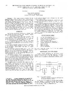
IV. SIMULATION RESULT Fig. 3 shows the simulation result of the DGS and the DMS harmonics termination load network. The used substrate is RT/duroid 5880 of Rogers with the dielectric constant of εr =2.2 and thickness of h=0.31 mils. The simulation has been performed using Ansoft HFSS version 11. The comparisons of reflection and transmission characteristics of the DGS and the DMS harmonic termination load networks are shown in Fig. 3. From the Fig. 3, it is obvious that the return loss and transfer characteristic of the DMS is almost similar with the DGS. The reflection characteristics of the DGS and the DMS are less than 20 dB at operating frequencies of 211~2.17 GHz. The insertion losses for the DMS and the DGS at frequency of 2.14 GHz are 0.08 dB and 0.12 dB, respectively.
947
The attenuation in case of the DMS at the second (4.22 GHz) and the third harmonic (6.42 GHz) are 28.48 dB and 29.88 dB respectively. The attenuation in case of the DMS is less than 27 dB for the frequency ranges between 4.22 GHz and 6.51GHz. Similarly, the attenuations in case of the DGS at these harmonics are 32.87 dB and 30.5 dB, respectively. Fig. 4 shows the group delay characteristics of the DGS and the DMS load networks which is almost similar. The group is measure of how long a signal to transverse the network and it is related to slow-wave effect. From the Fig. 4, the increasing value of group delay implies that the slow-wave factors of DGS and DMS load networks are increasing according to frequency. 0
-20 -30 -40 S11 @ DGS S21 @ DGS S11 @ DMS S21 @ DMS
-50 -60 -70
V. MEASUREMENT RESULT Fig. 6 shows the measurement results of the two units of the dumb-bell shaped DGS and the T-type DMS harmonic termination load network. From the experiment, the insertion loss of the DMS is 0.18 dB at fundamental frequency of 2.14 GHz. However, it is higher than simulation result due to SMA connector loss and measurement loss. Similarly, the attenuation at the second (4.28 GHz) and the third harmonic (6.42 GHz) are 27.47 dB and 28.10 dB respectively, which are good enough for the harmonic termination load network application. The attenuation is less than 27 dB for the frequencies ranges between 4.22 GHz and 6.51 GHz. 0 -10
0
1
2
3
4
5
6
7
8
Frequency [GHz] Fig. 3. Simulation results of the DGS and DMS harmonics termination load network
0.56 0.48 0.40
-20 -30 -40 DGS @S11 DGS @S21 DMS @S11 DMS @S21
-50 -60 -70
0.32
0
1
2
0.16
4
5
6
7
8
Fig. 6. Measurement results of the DGS and the DMS harmonic termination load network 0.56
DMS DGS
0.08 0.00 1.0
3
Frequency [GHz]
0.24
0.48
1.5
2.0
2.5
3.0
Group Delay [ns]
Group Delay [ns]
(b)
Fig. 5. Current distribution on: (a) the ground plane in the DGS and (b) the top conductor in the DMS.
S-parameters [dB]
S-parameters [dB]
-10
(a)
Frequency [GHz] Fig. 4. Simulated group delay characteristics of DGS and the DMS load network
Fig. 5 shows the EM simulation results of current distribution on the ground plane of the DGS harmonics termination load network and top conductor of the DMS. The defects in ground plane divert the current flow on the ground and as a result, it producing high ground impedance (inductance). Thus voltage drop at the ground plane is increased which is causes of increased emission. The ground plane defects will significantly increase the crosstalk between the traces if there is more than one interconnection in the circuit boards. These are one of deficiencies of the DGS. By adopting the DMS, the problems of the DGS can be solved as there is no leakage on the ground plane.
0.40 0.32 0.24 0.16
DMS DGS
0.08 0.00
1.0
1.5
2.0
2.5
3.0
Frequency [GHz] Fig. 7. Measured group delay characteristics of DGS and DMS load networks
Similarly, the insertion loss in case of the DGS is 0.24 dB at frequency of 2.14 GHz. The attenuations at second and third harmonic are 26.84 and 29.58 dB, respectively.
948
Fig.7 shows the measured group delay characteristics of the DGS and the DMS harmonic termination load networks. From the measurement result, it is obvious that the group delay characteristics of the DGS and DMS harmonic termination load networks are almost similar and are increasing according to frequency. Fig. 8 shows the photographs of the fabricated DGS and DMS harmonic termination load networks. DGS
VI. CONCLUSION We proposed the harmonics termination load network for the high efficiency PA applications using the DMS. The proposed structure is also compared with the DGS harmonics termination load network. The return loss and attenuation characteristic of the DMS for the operating frequency bands is almost similar with the DGS. Comparing the defected area, the DMS network has approximately one quarter of the area of the DGS at the same frequencies of operation. The proposed network can be applied to high power amplifier design as it has the low insertion loss at the fundamental frequency and much high attenuation characteristics at the harmonic frequencies. The ground problem of the DGS can be overcome by the proposed DMS structure. VII. [1]
Bottom Pattern
Top Pattern
[2] [3]
(a)
(b) [4] [5] [6] [7]
[8]
(c) Fig. 8. Photographs of the fabricated harmonic termination load networks: (a) the DGS top pattern (b) the DGS bottom pattern (c) DMS
949
REFERENCES
S. C. Cripps, Advanced Techniques in RF power amplifiers design, Norwood, MA: Artech House, 2002. A. J. Wilkinson, J.A. Everand, “Transmission-line load network topology for class E amplifiers,” IEEE Trans. Microwave Theory Tech., vol. 49, no. 6, pp. 1202-1210, Jun. 2001. Y. C. Jeong, S. G. Jeong, J. S. Lim and S. Nam , “A new Method to suppress harmonics using λ/4 bias line combined with defected ground structure in power amplifiers,” IEEE Microw. Wireless Compon. Lett. vol. 13 no. 12, pp. 538-540, Dec. 2003. J.S. Lim, C.S. Kim, D. Ahn, Y.C. Jeong and S. Nam ,“ Design of lowpass filters using Defected ground structure” IEEE Trans. Microwave Theory Tech., vol. 53, no. 8, pp. 2539-2545, Aug. 2005 J. S. Lim, Y. C. Jeong, D. Ahn and S. Nam, “Improvement in performance of power amplifier using Defected ground structure,” IEICE Trans. Electron., vol. E87-C, no. 1, pp. 52-59, Jan. 2004. J.S. Lim, G.Y. Lee, Y.C. Jeong, D. Ahn, and K.S.Choi, “A 1:6 unequal Wilkison Power dividers” Proceedings of 36th European Microave. Conference, pp. 200-203, 2006. J. A. T. Mendez and H. J. Aguilar, “Comparison of Defected ground structure and Defected microstrip structure behavior at high frequencies,” In IEEE international conference on electrical and electronics engineering (ICEEE) proceedings, pp. 7-10, Jun. 2004. J J.A.T. Mendez, H.J. Aguilar, F.I. Sanchez, I.G. Ruiz, V.M. Lopez and R.A. Herrera, “ A proposed Defected Microstrip Structure (DMS) behavior of for reduced Rectangular Antenna size” Microwave Optical Tech. Letters, vol.43, no.6, pp. 481-484, Dec. 2004