AbstractâA new three inputs and single output voltage-mode universal biquadratic filter with high-input and low-output impedance using three plus-type ...
IEEE TRANSACTIONS ON CIRCUITS AND SYSTEMS—II: EXPRESS BRIEFS, VOL. 54, NO. 8, AUGUST 2007
649
High-Input and Low-Output Impedance Voltage-Mode Universal Biquadratic Filter Using DDCCs Wei-Yuan Chiu and Jiun-Wei Horng
Abstract—A new three inputs and single output voltage-mode universal biquadratic filter with high-input and low-output impedance using three plus-type differential difference current conveyors, two grounded capacitors and two grounded resistors is presented. The proposed circuit offers the following features: realization of all the standard filter functions, that is, high-pass, bandpass, low-pass, notch, and all-pass filters, no requirements for component matching conditions, the use of only grounded capacitors and resistors, high-input and low-output impedance and low active and passive sensitivities. Index Terms—Active filters, current conveyors, differential difference current conveyor (DDCC).
I. INTRODUCTION
T
HE applications and advantages in the realization of various active filter transfer functions using current conveyors (CCs) have received considerable attention [1]. Second-order active filters with high-input impedance are great of interest because several cells of this kind can be directly connected in cascade to implement higher order filters [2]. Recently, many voltage-mode universal biquadratic filters with three inputs and one output were proposed [3]–[11]. The circuits in [3] and [4] employ two plus-type second-generation CCs (CCIIs) and one voltage follower. However, only the low-pass response enjoys the advantage of high-input impedance and the realization of [3] requires component matching conditions for the highpass, notch and all-pass responses. The circuits in [5]–[8] employ different types of CCIIs (one plus-type CCII and one minus-type CCII in [5]–[7], two plus-type CCIIs and two minus-type CCIIs in [8]). However, none of their responses have the advantage of high-input impedance and the all-pass response in [7] requires component matching condition. Chang and Tu [9] employed two plus-type CCIIs, two capacitors and three resistors with four inputs and single output to realize a universal biquad. However, none of its responses have the advantage of high-input impedance and the low-pass, notch and all-pass responses require component-matching conditions. Horng [10] proposed a high-input impedance voltage-mode universal biquadratic filter with three inputs and single output using three plus-type CCIIs. Manuscript received February 6, 2007; revised March 22, 2007. This work was supported by the National Science Council, Republic of China under Grant NSC 95–2221-E-033–082. This paper was recommended by Associate Editor G. Palumbo. The authors are with the Department of Electronic Engineering, Chung Yuan Christian University, Chung-Li, 32023, Taiwan, R.O.C. (e-mail: jwhorng@ cycu.edu.tw). Digital Object Identifier 10.1109/TCSII.2007.899460
However, this circuit employs floating capacitors and needs a voltage inverter to realize all-pass filter response. Moreover, the active and passive sensitivities are not small. In 2004, Horng [11] proposed two new high-input impedance voltage-mode universal biquadratic filters using three plus-type CCIIs. However, both circuits employ floating capacitors and one circuit needs voltage inverter to realize all-pass filter response. In this brief, a new high-input and low-output impedance voltage-mode universal biquadratic filter with three inputs and single output using three plus-type differential difference current conveyors (DDCCs) [12] is presented. The new circuit uses only two grounded capacitors and two grounded resistors, which are suitable for integrated circuit implementation [13]–[14]. The circuit needs neither an invertingtype voltage input signal nor any critical component matching conditions. Moreover, the circuit has low active and passive sensitivities. Since the implementation configuration of the plustype DDCC is simpler than that of the minus-type DDCC, the proposed circuit only employs the plus-type DDCCs. II. CIRCUIT DESCRIPTION The differential difference current conveyor (DDCC) was proposed in 1996 [12], and it enjoy the advantages of CCII and DDA such as larger signal bandwidth, greater linearity, wider dynamic range, simple circuitry, low power-consumption, high-input impedance and arithmetic operation capability [12]. Moreover, it has three high-input voltage terminals (Y terminals) that make easy to synthesize circuits. Using standard notation, the port relations of an ideal DDCC can be characterized by
(1)
where the plus and minus signs indicate whether the conveyor is configured as a noninverting or inverting circuit, termed DDCC+ or DDCC-. The proposed configuration is shown in Fig. 1. The transfer functions can be expressed as (2) From (2), we can see the following. 1) If (grounded), a second-order high-pass . filter can be obtained with
1549-7747/$25.00 © 2007 IEEE
650
IEEE TRANSACTIONS ON CIRCUITS AND SYSTEMS—II: EXPRESS BRIEFS, VOL. 54, NO. 8, AUGUST 2007
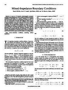
Fig. 1. Proposed high-input and low-output impedance voltage-mode universal biquadratic filter.
2) If (grounded), a second-order bandpass . filter can be obtained with 3) If (grounded), a second-order low-pass . filter can be obtained with (grounded) and , a second4) If . order notch filter can be obtained with 5) If , a second-order all-pass filter . can be obtained with Thus, the circuit is capable of realizing all filter functions. The circuit requires the minimum number of passive components with no requirement for matching conditions. , , and , are Moreover, the three input signals, connected to the high-input impedance input nodes of the three plus-type DDCCs (the y port of the plus-type DDCC), respec, is connected to the low-output tively. The output signal, impedance output node of the plus-type DDCC (the x port of the plus-type DDCC). So the circuit enjoys the advantage of having high-input and low-output impedance. Note that the low output impedance makes the proposed circuit easy to be connected to next stage without any buffer. Furthermore, the new circuit uses only two grounded capacitors and two grounded resistors, which are suitable for integrated circuit implementation. The employs of only plus-type DDCCs simplify the circuit configuration. III. SENSITIVITIES ANALYSIS Taking the nonidealities of the DDCC into account, the relationship of the terminal voltages and currents can be rewritten as
(3)
and denotes where the voltage tracking error from terminal to terminal of and the th DDCC, denotes the voltage tracking error from terminal to terminal of the th DDCC, and denotes the voltage tracking error from terminal to terminal of the th DDCC and and denotes the current tracking error of the th DDCC. The denominator of nonideal voltage transfer function in Fig. 1 becomes
(4)
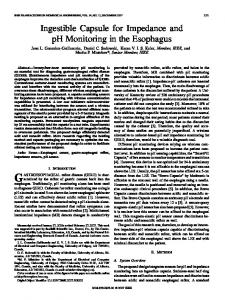
Fig. 2. CMOS realization of the plus-type DDCC.
The resonance angular frequency obtained by
and quality factor Q are
(5) (6) The active and passive sensitivities of
and Q are shown as
All the active and passive sensitivities are small. IV. SIMULATION RESULTS The proposed circuit was simulated using PSPICE. The DDCC was realized by the CMOS implementation in Fig. 2 [15] using TSMC 0.35- m CMOS technology process parameters. Referring to [12], the input transconductance elements are and , and ). realized with two differential stages ( and The high-gain stage is composed of a current mirror ( ) which converts the differential current to a single-ended output current . The output voltage of this amplifier can be expressed as (7) is the open-loop gain of the amplifier and is the where . Negative feedback was then applied from gate voltage of the output node of the gain stage (terminal X) to the input node ) (then ). If the open-loop gain of the (gate of amplifier is much larger than one, the relationship between the input terminal voltages can be obtained as (8) The output terminal Z is constituted with and which duplicates the current of the transistor . It can be clearly seen
CHIU AND HORNG: HIGH-INPUT LOW-OUTPUT UNIVERSAL BIQUADRATIC FILTER
651
TABLE I ASPECT RATIOS OF THE MOS IN FIG. 2
Fig. 5. Simulated frequency responses for the bandpass filter of Fig. 1 design with C = C = 30 pF and R = R = 35 k .
Fig. 3. Simulated amplitude-frequency and phase-frequency responses of the proposed notch filter.
Fig. 6. Time-domain input (upper signal) and output signal waveforms to demonstrate the dynamic range of the filter in Fig. 1.
Fig. 4. Simulated amplitude-frequency and phase-frequency responses of the proposed all-pass filter.
that both and flow simultaneously towards or away from the DDCC. The aspect ratios of the MOS transistors were chosen in . The biasing Table I and the power supply was was taken as . Figs. 3 and 4, respectively, voltage represents the simulated amplitude-frequency responses and phase-frequency responses for the notch and all-pass filters
which designed with kHz, pF and k . The large signal behavior of the circuit in Fig. 1 is investigated by a 150-kHz input signal and observing pF the bandpass output voltage designed k . Fig. 5 represents the simulated and amplitude-frequency responses for the bandpass filters and the time domain response is shown in Fig. 6. It is observed input voltage signal levels are possible without that 0.8 V significant distortion. Figs. 7 and 8, respectively, represents the simulated amplitude-frequency responses and phase-frequency responses for the all-pass filter with INOISE and ONOISE pF and k . designed V. CONCLUSION In this brief, a new three inputs and single output voltagemode universal biquadratic filter with high-input and low-output impedance is presented. The proposed circuit uses three plustype DDCCs, two grounded capacitors and two grounded resistors and offers following advantages: high-input and low-output
652
IEEE TRANSACTIONS ON CIRCUITS AND SYSTEMS—II: EXPRESS BRIEFS, VOL. 54, NO. 8, AUGUST 2007
impedance, low active and passive sensitivities, the use of only three plus-type DDCCs, the use of only two grounded capacitors and two grounded resistors, the versatility to synthesize low-pass, bandpass, high-pass, notch, and all-pass responses without component matching conditions. REFERENCES
Fig. 7. Simulated amplitude-frequency responses with INOISE and ONOISE of the proposed all-pass filter.
Fig. 8. Simulated phase-frequency responses with INOISE and ONOISE of the proposed all-pass filter.
[1] B. Wilson, “Recent developments in current conveyor and current-mode circuits,” Proc. IEEE Circuits, Devices, Syst., vol. 137, no. 2, pp. 63–77, Apr. 1990. [2] A. Fabre, F. Dayoub, L. Duruisseau, and M. Kamoun, “High-input impedance insensitive second-order filters implemented from current conveyors,” IEEE Trans. Circuits Syst. I, Fundam. Theory Appl., vol. 41, no. 12, pp. 918–921, Dec. 1994. [3] S. Ozoguz and E. O. Gunes, “Universal filter with three inputs using CCII+s,” Electron. Lett., vol. 32, no. 23, pp. 134–2135, Nov. 1996. [4] C. M. Chang and M. S. Lee, “Comment: Universal voltage-mode filter with three inputs and one output using three current conveyors and one voltage follower,” Electron. Lett., vol. 31, no. 5, pp. 353–353, Mar. 1995. [5] J. W. Horng, C. C. Tsai, and M. H. Lee, “Novel universal voltage-mode biquad filter with three inputs and one output using only two current conveyors,” Int. J. Electron., vol. 80, no. 4, pp. 543–546, Apr. 1996. [6] J. W. Horng, M. H. Lee, H. C. Cheng, and C. W. Chang, “New CCIIbased voltage-mode universal biquadratic filter,” Int. J. Electron., vol. 82, no. 2, pp. 151–155, Feb. 1997. [7] S. I. Liu and J. L. Lee, “Voltage-mode universal filters using two current conveyors,” Int. J. Electron., vol. 82, no. 2, pp. 145–149, Feb. 1997. [8] C. M. Chang, “Multifunction biquadratic filters using current conveyors,” IEEE Trans. Circuits Syst. II, Analog Digit. Signal Process., vol. 44, no. 11, pp. 956–958, Nov. 1997. [9] C. M. Chang and S. H. Tu, “Universal voltage-mode filter with four inputs and one output using two CCII+s,” Int. J. Electron., vol. 86, no. 3, pp. 305–309, Mar. 1999. [10] J. W. Horng, “High-input impedance voltage-mode universal biquadratic filter using three plus-type CCIIs,” IEEE Trans. Circuits Syst. II, Analog Digit. Signal Process., vol. 48, pp. 996–997, Oct. 2001. [11] J. W. Horng, “High-input impedance voltage-mode universal biquadratic filters with three inputs using plus-type CCIIs,” Int. J. Electron., vol. 91, no. 8, pp. 465–475, Aug. 2004. [12] W. Chiu, S. I. Liu, H. W. Tsao, and J. J. Chen, “CMOS differential difference current conveyors and their applications,” Proc. IEE Circuits, Devices, Syst., vol. 143, no. 2, pp. 91–96, Apr. 1996. [13] M. Bhusan and R. W. Newcomb, “Grounding of capacitors in integrated circuits,” Electron. Lett., vol. 3, pp. 148–149, 1967. [14] K. Pal and R. Singh, “Inductorless current conveyor all-pass filter using ground capacitors,” Electron. Lett., vol. 18, pp. 47–47, 1982. [15] H. O. Elwan and A. M. Soliman, “Novel CMOS differential voltage current conveyor and its applications,” Proc. IEE Circuits, Devices, Syst., vol. 144, no. 3, pp. 195–200, Jun. 1997.