Polarity Dependent Reliability of Advanced MOSFET Using MOCVD Nitrided Hf-silicate High-k Gate Dielectric J. Zhang, E. Zhao, Q. Xiang, J. Chan, J. Jeon, J.-S. Goo, A. Marathe, B. Ogle, M.-R. Lin, and K. Taylor Technology Development Group, AMD, One AMD place, PO Box 3453, MS 143, Sunnyvale, CA 94088 Email:
[email protected], Tel.: (408)749-3963
ABSTRACT
RESULTS AND DISCUSSION
We report reliability of MOSFETs with MOCVD nitrided Hfsilicate (HfSiON) high-k gate dielectric. HfSiON has shown superior electrical characteristics, such as low leakage relative to SiO2 and high mobility compared to other high-k gate dielectrics [1]. SILC is found to be comparable to SiO2 and better than Hf-silicate without nitridation. TDDB and BTI reveal significant difference between inversion and accumulation mode. Polarity-dependent charge trapping and defect generation are observed and attributed to asymmetric band diagram as well as dissimilar charging processes in two stress modes. Trap-assisted tunneling is evidenced by its strong temperature dependence. Charge pumping tests indicate higher interface density compared to SiO2/Si. The Weibull slope is determined to be about 3, showing robust wear-out quality of the high-k dielectric.
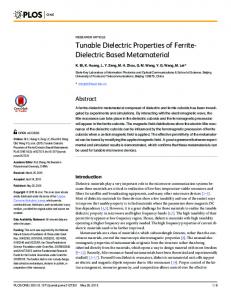
An HRTEM image of HfSiON under poly-Si gate is shown in Fig. 1. A very thin interfacial layer formed between the high-k film and the substrate can be seen. It will significantly affect the overall gate dielectric reliability.
INTRODUCTION
EXPERIMENT NMOS transistors have been fabricated using nitrided Hfsilicate by MOCVD. Nitridation of Hf-silicate is performed in situ during the Hf-silicate deposition. Poly-Si gate electrodes are deposited directly on HfSiON by CVD. The conventional MOS process is used. The high-k films remain amorphous after anneal up to 1025 oC. For reliability evaluation, both high-k and SiO2 wafers are stressed under either inversion or accumulation mode at room and elevated temperature, respectively. Time-dependent dielectric breakdown (TDDB), stress-induced leakage current (SILC), bias and temperature instability (BTI), and charge pumping (CP) tests are conducted. Highly accelerated stress conditions are used intentinally in order to expose potential reliability problems.
Fig. 1. Cross sectional TEM of nitrided Hf-silicate (HfSiON).
Fig. 2 shows a CV curve of an HfSiON NMOS capacitor with EOT of ~11 Å and inversion Tox of ~21 Å. The CV curve is fitted with NCSU’s CVC program to get EOT. These data indicate good scalability of this high-k material. 180 160
Raw data Simulation
140 120
Cg (pF)
As ultra-thin SiO2 rapidly approaches its physical scaling limits in modern VLSI technology, it is important to identify an alternative high-k gate dielectric. In spite of such critical issues as controversial interpretation of channel mobility degradation, thermal stability, poly gate compatibility, dopant penetration, and EOT increase due to uncontrolled oxidation, some candidates have been identified and investigated in detail. Most recently, nitrided Hf-silicate by reactive sputtering has demonstrated promising results [2]. We have observed that this material is thermally stable up to 1025 oC in contact with poly-Si gate; nitrogen content and profile can be engineered so that both oxygen and dopant penetration can be efficiently blocked without compromising channel mobility. We have also demonstrated about 11 Å EOT and over 80% SiO2 channel mobility for poly gate NMOS transistors with HfSiON gate dielectric [1]. These performance numbers are among the best for poly gate high-k transistors reported to date. In this paper, we report reliability of NMOS transistors with this high-k gate dielectric. The polarity dependence of reliability has been of great interest for gate dielectrics [3,4]. The study may shed light on application of SOI transistors in a transmission gate.
EOT=~11A
100 80 60 40 20 0 -2.0
-1.5
-1.0
-0.5
0.0
0.5
1.0
VG (V)
Fig. 2. CV curves of a capacitor for two typical silicate films.
In order to compare high-k films using different recipes, we conducted SILC measurement under highly accelerated stress conditions. As seen in Fig. 3, HfSiON (silicate II) shows comparable
SILC to SiO2 and better than Hf-silicate without nitridation (silicate I). A large amount of nitrogen in the film is believed to block the oxygen diffusion and dopant penetration without compromising channel mobility. Therefore this work is focused on HfSiON.
1.E+01
silicate I
silicate II (a) silicate II (b)
control
1.E+00
1.E-01 10.0
12.0
14.0
16.0
18.0
20.0
EOT (A)
Fig. 3. Comparison of SILC after 2.8V stress for 60 sec at 25 C. The TDDB behavior showed significant stress polarity dependence (Fig. 4). Note considerable difference of breakdown currents in inversion and accumulation mode and shorter time to breakdown in accumulation mode. Similar observation on polarity gap of Weibull slope of NMOS and PMOS capacitors in accumulation was reported recently [5].
1.8 VG=2.8V VG=2.6V
This polarity dependence has drawn wide attention of the gate oxide reliability community. In a very recent work on ultra-thin oxides, both QBD and tBD were demonstrated dependent on the stress polarity [3]. Many studies indicates that an interfacial layer or a structural transition layer near the substrate is responsible for the polarity dependence [5, 6, 7]. In general, two scenarios exist: a “soft” interfacial layer, or a “hard” interfacial layer. In the first case, when the gate is under a negative stress, electrons injected from the cathode can build up sufficient kinetic energy in a needed traveling distance and generate more positive species (holes and/or H-related species) which are then injected back to the cathode and cause oxide damages along the path. In the second case, the interfacial layer acts as a diffusion barrier for the positive species traversing the oxide from the anode in the negative VG stress mode. Both situations are in agreement with the anode hole injection (AHI) and/or anode hydrogen release (AHR) mechanisms. We conclude that the polarity dependence is intrinsic to stacks or stack-like structures and the interfacial layer plays an important role in the overall gate dielectric reliability. The reason behind it is the asymmetric band diagram and dissimilar charging processes in two stress modes. 1E-04 Stress VG=2.47V
1.4 |IG| (A)
IG/IG0
1.6
1.2 1 1
10 100 Time (sec)
1E-06 t=0 t=1min t=2min t=3min t=5min
1E-08
1000 1E-10 0
100.0
1E-04
0.5
1
1.5
Stress VG=-2.47V
|IG| (A)
VG=-2.47V
IG/IG0
IG/IG0-1
1.E+02
The polarity dependence is further probed through Ig, Id, and Gm characterizations as shown in Fig. 5, 6, and 7. In Fig. 5, we observe a greater stress effect on the gate leakage current (SILC) in the accumulation stress mode, indicating more oxide damage caused by the negative gate stress. Fig. 6 and 7 reveal obviously different consequences of PBTI (positive bias and temperature instability) and off-state stress. Fig. 6 shows that the threshold voltage shifts in both PBTI and off-state stress modes, but in opposite direction. PBTI is usually minimal in SiO2. Furthermore, the negative gate stress does not only reduce the saturation current, also increases the triode current and thus degrades the sub-threshold slope. This is primarily attributed to the interface states generation, contrast to fixed charges and oxide traps that lead to the parallel shift of the ID-VG curve. Fig. 7 shows that although Gm,max shifts in opposite direction due to Vt shift, its amplitude reduction is close despite of different charge trapping mechanisms.
10.0
1E-06 t=0 t=1min t=2min t=3min t=5min
1E-08
1E-10
1.0
0
1
10 100 Time (sec)
1000
Fig. 4. Distinct time dependent breakdown features in inv. (top) and acc. mode (bottom).
0.5
1
1.5
VG (V)
Fig. 5. SILC under two stress modes at 100 C. Worse SILC effect is seen in accumulation mode stress (bottom).
1E-03
To investigate the interface property, charge pumping tests are conducted. The data (Fig. 8) show higher Dit for HfSiON films compared to SiO2. It is in the order of 1012 cm-2. There still is room to improve the interface quality, which may also improve the channel mobility, consequently.
Stress VG=2.47V
ID (A)
1E-04 1E-05
t=0 t=5min
1.2E-06
1E-06 VD=0.05V
1E-07 -0.5
ID (A)
0.5
8.0E-07
1.5
HfSiON
Icp(A)
1E-03
SiO2
Stress VG=-2.47V
4.0E-07
1E-04
0.0E+00 -1.2
t=0 t=5min
1E-05
-0.7
-0.2
0.3
VGBL VD=0.05V 1E-06 -0.5
0
0.5 VG (V)
1
1.5
Fig. 6. ID-VG under two stress modes at 100 C. Dissimilar charge traps are reflected by different Vt shifts and subthreshold slope difference. 6E-04
Stress VG=2.47V t=0
Gm (S)
4E-04
t=5min
Fig. 8. Charge pumping result for HfSiON compared to control wafer.
High trap density in high-k films also results in trap assisted tunneling, as evidenced by the stronger temperature dependence of tunneling leakage in high-k films compared to that in SiO2 (Fig. 9). The ratio of IG at 100 oC and at 25 oC is presented for both SiO2 and HfSiON. At higher bias, where the field emission process usually dominates and is weakly temperature dependent, we see stronger temperature effect in HfSiON. This is a direct evidence of FrenkelPoole tunneling. High trap density can be further reduced by process optimization.
2E-04
Gm (S)
6E-04
VD=0.05V 0
0.5
1
2.0
1.5
IG(100C)/IG(25C)
0E+00 -0.5
Stress VG=-2.47V t=0
4E-04
t=5min 2E-04
0E+00 -0.5
SiO2 control HfSiON
1.8 1.6 1.4 1.2 1.0
VD=0.05V
1 0
0.5 VG (V)
1
1.5
1.1
1.2
1.3
1.4
1.5
VG Fig. 9. Temperature dependence of gate current at high VG for HfSiON compared to control wafer.
Fig. 7. Gm-VG under two stress modes at 100 C. Though Gm,max shifts in opposite direction due to Vt shift, its amplitude reduction is close despite of different charge trapping mechanisms.
o
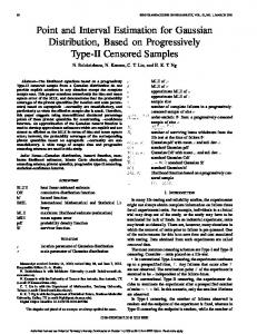
Fig. 10 shows the Weibull plot of TDDB data at 2.5 V and 100 C. The Weibull slope is about 3, showing the robust quality of the
high-k dielectric in terms of area scaling and failure rate scaling of maximum Vcc extraction. This value also indicates that the percolation model still holds for this thin high-k material. The bound lines in the graph are lower and upper 95% confidence level of the maximum likelihood estimate. Worthy to note here, although the high-k film shows tight Weibull distribution, the long-term lifetime has yet to be evaluated for future applications.
CONCLUSIONS Reliability of MOCVD nitrided Hf-silicate with superior electrical characteristics has been investigated. SILC is found comparable to SiO2 and better than Hf-silicate without nitridation. TDDB and BTI characteristics show significant discrepancy in inversion and accumulation stress modes. Polarity-dependent charge trapping and defect generation are observed and attributed to the asymmetric band diagram and dissimilar charging processes in two stress modes. Frenkel-Poole tunneling is evidenced by its strong temperature dependence. Charge pumping results revealed high Dit compared to SiO2/Si. The Weibull slope of TDDB was determined to be about 3. With further process optimization and reliability improvement, we believe nitrided Hf-silicate is a promising high-k gate dielectric for advanced CMOS applications.
ACKNOWLEDGEMENT The authors acknowledge D. Gilmer, H. Tseng and P. Tobin, APRDL, Motorola, for their help in wafer processing.
REFERENCES
Fig. 10. Weibull plot of TDDB data. The Weibull slope is 3.2±0.3.
[1] Q. Xiang, et al., To be published, 2002. [2] R.T.P. Rotondaro, et al., VLSI Tech Dig., #15-2, 2002. [3] E. Wu, et al., IRPS Proc., p.60, 2002. [4] D. DiMaria, APL, 68, 3004, 1996. [5] A. Kerber, et al., VLSI Tech. Dig., #8-3, 2002. [6] L. K. Han, et al., IEDM Tech. Dig., 617, 1994. [7] R. Degraeve, et al., IEDM Tech. Dig., 327, 1996.