High-Level Design Approach for the Specification of Cognitive Radio Equipments Management APIs Christophe Moy SUPELEC/IETR Rennes, France
[email protected] Abstract Cognitive Radio (CR) equipments are radio devices that support the smart facilities offered by future cognitive networks. Even if several categories of equipments exist (terminal, base station, smart PDA, etc.), each requiring different processing capabilities (and associated cost or power consumption), these equipments have to integrate also a set of new capabilities as regards CR support, in addition to the usual radio signal processing elements. This implies real-time radio adaptation and sensing capabilities, but not only. We assert that it is necessary to add inside the radio equipments some management facilities for that purpose, and we propose in this paper a high-level design approach for the specification of a management framework. This includes a set of designing rules, based on hierarchical units that are distributed over three levels, and the associated APIs necessary to efficiently manage CR features inside a CR equipment. The proposed architecture is called HDCRAM (Hierarchical and Distributed Cognitive Architecture Management). HDCRAM is an extension of a former hierarchical and distributed reconfiguration management (HDReM) architecture, which is derived from our previous research on Software Defined Radio (SDR). The HDCRAM adds to the HDReM’s reconfiguration management facilities the necessary new management features, which enable the support of sensing and decision making facilities. It consists in the combination of one Cognitive Radio Management Unit (CRMU) with each Reconfiguration Management Unit (ReMU) distributed within the equipment. Each of these CRMU is in charge of the capture, the interpretation and the decision making according to its own goals. In this Cognitive Radio context, the term “decision” refers to the adaptation of the radio parameters to the equipment’s environment. This paper details the HDCRAM‘s management functionality and structure. Moreover, in order to facilitate the early design phase of the management specification, which is new in radio design, HDCRAM has also been modeled with a meta-programming language based on UML. But beyond the first objective of high-level specification, we have also derived a simulator from the obtained meta-model, thanks to the use of an executable language. This gives the opportunity to specify the CR needs and play a wide variety of scenarios, in order to validate the CR equipment’s design. This approach provides high-level design facilities for the specification of cognitive management APIs inside a cognitive radio equipment.
1.
Introduction
The design of cognitive radio (CR) equipments will not be done efficiently if one uses the same tools as those used for the design of conventional radio equipments. One reason is that designing such a radio device is not solely a radio signal processing issue anymore. Of course, as in many other industrial domains, such as aeronautics, it becomes a hardware/software mixed issue with a plurality of capabilities and running modes on the one hand. But on the other hand, designing cognitive radio equipments also consists in designing the necessary management needed to support the real-time sensing of the environment and the real-time adaptation of the signal processing. Signal processing in our approach is not restricted to the physical layer and also includes all layers’ signal processing, up to the application layer. Another reason is that the range of ways a CR equipment will have to run, will be very wide compared to that of the current radio equipment operation. Abstraction is necessary during the design phase of a CR equipment. In this respect, this paper proposes a high-level design approach,
1
integrating the design rules needed for the management of the signal processing operators, as well as the exploration means as regards the operation modes. Even if designing the signal processing part of a radio chain is not an easy task, it is however usual. The new design aspect lies in the management part and the associated impact on the signal processing, which has to be flexible. The aim of the approach proposed in this paper is to help the designer on that point. It is not within the scope of the proposed approach to impose design tools and technologies. However, it helps to define and refine the management architecture’s Application Programming Interfaces (APIs), since the latter supports the cognitive radio signal processing. This paper differs from the majority of publication on cognitive management as they usually have a networking approach. After a justification of the importance of investigating CR equipments management in both terminal-centric and
network-centric
cases,
this
paper
explains
why
the
cognitive
management
(including
reconfiguration management) has to be designed as being the heart of the equipment itself. The paper is organized as follows. In the first part, we describe our view of the cognitive radio topic. In the next part, the issue of future cognitive radio equipments design is raised. The following section proposes a high-level design approach for cognitive radio equipment, and especially for the management architecture. Finally the necessary exchanges and interfaces between the elements of the management architecture are detailed in order to provide the APIs of the management architecture.
2.
Cognitive radio 2.1.
Cognitive Radio principles
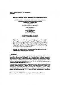
Cognitive radio has been introduced by J. Mitola in [1] and [2]. Mitola argues that radio will become more and more autonomous, and that thanks to the support of flexible technology, it will acquire some degree of self-autonomy, in order to dynamically modify its functionality. As explained in the schematic displayed in Figure 1, this relies on a cognitive cycle. Figure 1(a) is from [1] and we propose to simplify it as in Figure 1(b) for our purpose. Three main steps are kept: •
observe: gathers all the sensing means of a CR,
•
decide: represents all that implies some degree of intelligence including learning, planning
•
adapt: reconfigures the radio, designed with SDR principles in order to be as flexible as
decision making, possible.
Figure 1 – (a) Mitola’s cognitive cycle, (b) simplified version
In our approach, we address sensing in its largest acceptation, as in Mitola’s first publications. However, because of the high financial pressure linked to spectrum issues, CR is often restricted in the research 2
community to the spectrum management aspects as in [3][4]. Opportunistic spectrum access approaches are explored, in order to increase the global use of the spectrum resources. In our opinion, all the information that can help the radio to better adapt its functionality for a given service in a given environment, in other words under given constraints, is worth being taking into account. Then as we make no restriction on the sensors’ nature, it is possible to draw the general approach exposed in Figure 2.
Figure 2 – Simplified OSI model for a cognitive radio context
We classify sensors in Figure 2 in accordance with the OSI layers they correspond to, with a rough division in three layers. We can link especially all the sensing information related to the physical layer, to the lower layers of the OSI model: propagation, power consumption, coding scheme, etc. At the intermediate level lies all the information that participates to vertical handovers, or can help to make a standard choice, as a standard detection sensor for instance. The network load of the standards supported by the equipment may be of interest also. It also includes the policies concerning the vicinity, the town or the country. The highest layer is especially related to the applications and anything as regards human interaction with the communicating device. It is related to all things concerning the user, his/her habits, preferences, policies, and profile. Note that the classification proposed here is also related to three well-known concepts, frequently referred to in the literature: •
context awareness for higher layers [5],
•
inter-operability for intermediate layers [6],
•
link adaptation for lower layers [7].
All this may be combined, in order to proceed with cross-layer optimizations. According to us, this is one of the responsibilities of the cognitive engine.
2.2.
Cognitive radio in the short term
Cognitive radio is a revolution in the way of tackling radio processing. However, it is based on principles that have already been used in radio systems and equipments. We may consider for instance that adaptive signal processing for radio algorithm is a first introduction of cognitive radio. Adaptive signal processing indeed aims at changing the processing radio functions, such as an equalizer, or a RAKE receiver, etc., by sensing the equipment environment, the channel impulse response in these 2 examples, in order to adapt the function in real-time to this environment. The channel estimator required in the context of a RAKE receiver is nothing else than a sensor. From our perspective, the metrics of interest are the phase and energy of the paths to be re-injected in the taps of the RAKE filter [8]. The decision making consists in the computation (and the choice) of the combining method, such as the maximum ratio or equal gain combining, the single or largest path selection methods [9]. The implementation of the RAKE is reconfigured accordingly. We can see that we find here the 3 steps of 3
the simplified cognitive cycle featured in Figure 1(b): observe, decide, adapt. So we may wonder if cognitive radio is bringing anything new. Cognitive radio indeed aims at: -
generalizing this to many radio features (and we’ll see later that generalization can also be extended to functions through all OSI layers),
-
sharing the sensing information within the entire equipment instead of restricting the information to a sole extra processing block.
If we go back to the RAKE example mentioned before, we can wonder if the channel impulse response provided by the channel estimator could be used for other purposes in the cognitive equipment, and at the network level. Inside the equipment, on the one hand, the channel impulse response could be used to extract information about a location‘s geographic details for instance (indoor, urban, rural area). On the basis of this information, the equipment could look for new choices of radio connectivity, which are more suited to the current service (switch from UMTS to WiFi inside a building for a video application), or could relax some processing operation in order to save some battery power (benefit from the UMTS channel estimation so as to switch off the GPS device when entering a building, as it will not be working properly anymore). At the network level, on the other hand, the impulse response of a primary terminal can be used by the base station to null the interference, and this enables to multiplex (on the same band) information to secondary users through the use of a Vandermonde precoder known as the Vandermonde Frequency Division Multiplexing (VFDM) [10]. In both situations, a framework has to be added inside the equipment in order to allow the support of these cognitive features and benefit from them in the equipment itself, or to send them to the network. It is the kind of facilities that have to be taken into account and which can be inserted at the very beginning of a cognitive radio equipment’s design. This is exactly what the method proposed in this paper provides the designer with.
2.3.
Medium term
The introduction or the generalization of cognitive radio in the radio field is mainly a matter of regulation indeed. The reason of the recent increased interest in spectrum-related cognitive radio issues is directly linked to the FCC “Cognitive Radio Report and Order” published in 2005 [11], and which follows the 2001 “SDR Report and Order” [12]. FCC has also been opening the door to the secondary (e.g. not licensed) users‘ potential insertion into the TV broadcasting bands [13] in 2004, and allows secondary users to use the primary users’ spectrum when the latter is available. The condition is to never jam a primary user who pays for spectrum access. As a consequence of the FCC momentum towards cognitive radio, IEEE standardization is very active on cognitive radio related actions. Several IEEE standards groups indeed are working on issues related to spectrum sharing. IEEE 802.22 is aiming to create Wireless Regional Area Networks (WRANs) based on cognitive radio through the secondary usage of TV bands. In the USA, WRANs will be designed to opportunistically use the 52 to 862 MHz VHF and UHF TV bands.. IEEE SCC41 is a working group, whose goal consists in developing standards for technologies, architectures, and any facilitators, and this in order to realize dynamic spectrum access networks. Furthermore, both IEEE 802.16h and IEEE 802.11y are working on interference management and efficient resource allocation in shared (unlicensed) bands. 4
2.4.
Long term
Static frequency allocation was based on early 20 th century technology. It enabled the boom of radio technologies during the 20 th Century, but it is now holding back its future expansion. Let us forget all the existing rules. Futuristic CR scenarios may be considered in light of the spectrum management. We may even imagine in the very long term, a fully deregulated spectrum access in which all radio connections features would be defined on-the-fly: carrier frequency, modulation, data rate, coding scheme, etc. It would consist in a real-time creation and adaptation of the complete protocol stack. Regulatory issues, in addition to technological challenges, would have to be overcome. Regulators will have to state the conditions to be respected prior to using a spectrum band. How should 2 transceivers first contact and how can they evaluate the potential radio connectivity solutions? What are the differences/commonalities in the context of a terminal connecting to a base station or another terminal in an ad-hoc mode (which will be generalized in the future thanks to cognitive radio indeed)? Is a worldwide boot or pilot channel [14] necessary? We can see that this raises both terminal and network issues. As already stated, we focus in this paper on the terminal aspect. Our current queries relate to the short term needs in terms of cognitive radio equipments design approach, but we need to keep in mind the longer term challenges in order to provide the necessary generalization, which will enable the current approach to remain meaningful and hold its characteristics.
2.5.
Terminal-centric or network-centric approach of CR
Whereas past decades researches in the radio communication approach concentrated on increasing point-to-point data rate at the lowest power consumption level, the trend is now to consider the network load so as to optimize the global system capacity, or at least an entire cell or a set of cells. The results may be in total opposition: increasing the throughput on one point-to-point radio link resulted in a decrease of the surrounding users’ throughput and a diminution of the global cell capacity [15]. Cognitive radio, on its “spectrum” side, aims at tackling the global capacity issue from the network point of view. Then cognitive radio is considered as a solution to improve the global system capacity through a better use of spectrum. Two approaches of cognitive radio are usually considered in this context: network-centric or terminal-centric [16]. The network-centric approach, on the one hand, derives from the current topology of wireless networks with a centralized view. The network is indeed probably the best place to centralize the metrics and send orders through the equipments to the network. As highly computational optimization algorithms will be necessary for cognitive radio, it makes sense to imagine that such a demanding processing power can only be provided by powerful processors and devices, which are not compatible with the embedded environment of a terminal. However, a CR network implies to use a sub-part of the capacity, in order to exchange cognitive information about every pieces of the network, in the air, but also in the infrastructure. We only consider in this paper the air aspect of the network. This implies a signaling overhead that diminished the global capacity for data transmission. This overhead is all the worse if the system is varying very fast, but could be acceptable in long coherence time conditions [16]. On the other hand, a terminal-centric view may be justified this way. First of all, the terminal itself is the best place to gather information with regard to its own environment and take accurate adaptation decisions. This enables to distribute (through many terminals) the processing load of the optimization process. In order to make some decisions taking into account the surrounding terminals, the terminal can benefit from data coming from the network so as to summarize the global conditions of the area, which limit the signaling overhead compared to that of a network-centric approach. Sending the total 5
cognitive information from all terminals to the network would be much more bandwidth consuming, especially if the system environment varies quickly. Consequently, a terminal-centric approach should be privileged in short coherence time conditions. Anyway, if you consider CR from a global point of view, and not only from its capacity/spectrum aspect, it is possible to derive cognitive features that have no impact on the network side. This is the case with battery saving features, or processing improvement. This makes sense in such scenarios. In order to improve the reception quality, more efficient algorithms could be activated (more Turbo Coding iterations for instance, etc.) without any impact on the transmitter side. An adaptation could also be launched in order to lower the communication price (switching from UMTS to WiFi when coming back home), and set as a user contract’s feature. This is anyway an order coming from the user’s side that does not require any order or complementary information from the network. Only the user’s profile and the individual WiFi access details are necessary, the latter being known by the terminal. As a conclusion, even if we can not decide on a network-centric or terminal-centric dominance, but we may bet on a mix of those approaches, there is in any case a need to have cognitive radio capabilities inside mobile equipments (smart terminals, PDA, etc.) and base stations so as to support the global network cognitive radio features. Cognitive radio equipments will have in all cases to send metrics to the network and to make decisions and adapt their own behavior: this will be made on the basis of their own knowledge of their environment, as stated by the cognitive cycle of Figure 1(b). The management architecture for cognitive radio equipments proposed in the rest of this paper, is an answer to both extreme cases (terminal-, network-centric) and any other intermediate approach. It is a framework, which means that it provides appropriate rules to deal with real-time adaptation (real-time decision making and reconfiguration) but the choice of these features‘ implementation is entirely up to the designer.
3.
Future radio design 3.1.
Software Defined Radio design
The radio design experienced a rapid evolution in the 90’s, based on the military research work started in the 70’s and 80’s that gave birth to the SpeakEasy project [17] for instance. Radio design naturally turned to the implementation of radio processing in the digital domain. The advantages are numerous: ease of development, with the possibility to re-use previous designs and change the design even at a very late stage of the development, opportunity to use common hardware for different radios, turning to the possibility to design multi-standard radio, etc.. Joe Mitola [18] formalized the software radio ideas in 1991 and this was the beginning of the spread of these ideas to the whole research community. Software Defined Radio (SDR) turned the concepts to more realistic implementation solutions. But as often thought, SDR is not only a matter of designing the radio within the digital domain. The real heart of SDR design is the integration of reconfiguration management features in the radio design [19]. It is a necessary solution so as to use reconfigurable or reprogrammable devices [20], but it is not sufficient to support all desired SDR capabilities (sampling and carrier frequency switch, real-time signal processing adaptation in DSPs or FPGAs, etc.). Reconfiguration management has to be considered at the very early design phase of an SDR equipment. As a consequence, designing an SDR equipment consists in crossdesigning: -
a flexible hardware platform,
-
the radio processing elements (in software or firmware, or wired),
-
an infrastructure to support reconfiguration management.
6
It is out of the scope of this paper to deal with the hardware platform and radio processing (see [18][21][22] for that). This paper focuses on the management features for cognitive radio equipments, and SDR management is a part of this issue, from our point of view. Several levels of reconfiguration management must be distinguished in order to take advantage of the hardware’s reconfiguration capacity: (1) at design time in order to facilitate the development, (2) at deployment in order to give an abstraction of the hardware devices, (3) at run-time in order to adapt the radio behavior while operating. As we move from (1) to (3), more enhanced services have to be provided by the management in terms of reconfiguration. Depending on the degree of flexibility and the targeted goal, several solutions have been proposed concerning the management side of the design. The most famous one is the SCA (Software Communication Architecture) proposed in the USA military context [23][24][25]. The SCA is the answer to the US Department of Defense (DoD) requirements in terms of portability and inter-connectivity between SDR equipments manufactured by different providers. The way to answer this has been to propose an abstraction of the hardware for the radio software application (portability) through OS (Operating System) and ORB (Object Request Broker) techniques, and to define APIs between the management elements thanks to the IDL (Interface Description Language) language (inter-connectivity). To sum-up, the idea was to transpose personal computer features, such as portability and Plug&Play, to radio equipments. Consequently the SCA provides the designer (and the user) with facilities for the deployment of radio applications whatever the underlying hardware is. It is clearly in the number (2) category given above, and does not address the real-time adaptation of the radio parameters during operation. However, it can dynamically deploy (respectively stop) a new (respectively deployed) radio protocol stack whereas another one is already running. The SCA is currently the sole industrial solution (even if restricted to the military domain) because of the advance launch of this proposal (in 1998) and the DoD funds’ attraction. However it suffers from technical limitations (generated by CORBA in particular), leading to a decrease in terms of real-time performance. On the European side, on the other hand, the lack of military demand permitted the birth of several proposals, but still at the research level. At a commercial and academic level, E2R proposed some management architecture spread at both network and equipments side [26]. This was an extension of the equipment level proposed in [19]. UPC’s P-HAL goes even beyond while proposing a management and an equipment design framework, including concepts quite close to those of the SCA, but without the SCA real-time limitations [27]. Generic approaches derived from the computer world may offer some technical solution to SDR. It helped to define the SCA, with the use of CORBA, POSIX, and XML technologies. However, the realtime (embedded) context of SDR is often too demanding. The abstraction provided par Java Virtual Machines for instance would really address the portability issue, and would allow to run, on any hardware, any radio protocol stack developed with this software. But the price to pay in terms of loss of performance (real-time, power consumption, memory, indeed cost) is too high. That is why we argue, on the basis of the evidences provided by the analysis of the SDR’s particular constraints [28], that SDR customized solutions are needed. However we can note that all the items which can be found both in the embedded and adaptive real-time processing intensive domain, are also appropriate. Video processing for instance has very close characteristics, and consequently very close design solutions [29]. Furthermore, video processing is also investigating adapting processes. For instance, the Reconfigurable Video Coding (RVC) working group for MPEG standardization [30] is dealing with this topic. The solution we proposed in [28] for the management of reconfiguration is called HDReM for Hierarchical Distributed Reconfiguration Management. Like SCA and P-HAL, it is a 7
reconfiguration management framework at the equipment level, but aiming at offering an architecture for the real-time reconfiguration of an SDR-oriented radio processing, e.g. implemented in a reconfigurable or reprogrammable hardware as well as ASICs.
3.2.
Cognitive Radio Equipment
We can derive from the considerations of paragraph 2.1 what should be the ‘components’ of a CR equipment and Figure 3 exposes schematically the view of a CR equipment structure that can be derived.
smart sub-system
stimuli
analysis
orders decision
learning user
network environment hardware
SDR communication sub-system
sensing means
Application layer …
adapting means
Multiple physical layers Multiple Multiplephysical physicallayers layers
electro-magnetic environment
Figure 3 – Cognitive radio equipment functional block diagram
The SDR communication sub-system is composed of multiple radio protocol stacks (from the physical layer to the application layer) executed in a flexible hardware (and the corresponding necessary software such as drivers and the board support package) platform. Let us just stress that it should include in particular a reconfiguration management software architecture. At the equipment level, as much as cognitive radio is an extension of software radio towards autonomous adaptation, a cognitive management is an extension of a reconfiguration management [31]. As explained in Figure 3, in order to transform a SDR into a CR, two main parts need to be added: some sensing means and a smart subsystem. The term “sensors”, in our view, refers to the combination of electronic devices, and algorithms that translate the signals into metrics of interest. For instance, we may consider that the channel estimator already evoked in paragraph 2.2 is a sensor, as well as any other set of processing functions that extract metrics from the environment. A thermometer and the power level indicator of the equipment’s battery are sensors also. This information feeds the smart or cognitive engine of the CR equipment which then takes adaptation decisions for the protocol stack at any layer (from radio to application layer) accordingly. This means that reconfiguration may be done, in order to adapt the behavior of the equipment to the situation revealed by the sensors of the equipment, or sent by the network, or both of them. Four categories of sensing information, worth to be taken into account, are given in Figure 3 [32]: −
electromagnetic environment: spectrum occupancy, Signal to Noise Ratio (SNR), multi-paths propagation, etc.
−
hardware environment: battery level, power consumption, processors using rate, FPGAs gates occupation, etc.
−
network environment: telecommunication standards (GSM, UMTS, WiFi, etc.), operators and services available in the vicinity, traffic load on a link, etc.
−
user-related environment: position, speed, time of day; user preferences, user profile (access rights, contract, etc.), video and audio sensor (presence detection, voice recognition), etc. 8
Since there is an important discussion within the community to determine whether most of the intelligence capacity should be contained in the network or in the terminal, as discussed in paragraph 2.5., we believe that a combination of both is worth. Depending on each situation, one orientation maybe privileged from time to time. Anyway, the equipment’s cognitive management scheme proposed in this paper is completely compatible with both network-centric and terminal-centric cognitive radio management. Its complexity of course is lowered in the context of a mostly network-centric approach.
3.3.
Cognitive Radio equipments design proposal: HDCRAM
As reconfiguration management has to be considered at the very early design phase of an SDR equipment, a cognitive management architecture has to be included at the very early stage of a cognitive radio equipment’s design. In accordance with the previous paragraph 3.2, cognitive radio equipments should be then composed of: -
a flexible hardware platform,
-
the radio processing elements (in software or firmware, or wired),
-
sensing processing elements or devices,
-
an infrastructure to support both reconfiguration and cognitive management.
This is what HDCRAM provides to a cognitive radio equipment, whatever the hardware composition of the platform is. HDCRAM stands for Hierarchical and Distributed Cognitive Radio Architecture Management.
HDCRAM
has
been thought
to
support
the
management
of
multi-processing
heterogeneous platforms composed for instance of DSPs, GPPs, FPGAs, ASICs, etc. It has been firstly introduced in [31]. The present paper does not describe in detail HDCRAM. This can be found in [33]. We briefly remind here that, in order to support the reactivity needed for a real-time cognitive behavior in an heterogeneous hardware platform, HDCRAM is composed of 3 hierarchy levels. These 3 levels offer a management framework (or architecture), on top of the processing operators, considered here in its widest acceptation, e.g. any processing function from the radio to application layer, but also processing functions for sensing purposes, hardwired devices, etc.. We are clearly addressing a crosslayer view of the cognitive management as any information from any OSI layer can provide useful information to adapt the protocol stack globally. Each of the 3 HDCRAM levels is made of both a cognitive and a reconfiguration management sub-part, as shown in Figure 4.
9
Cognitive Management
Reconfiguration Management
Level 1
Cognitive Manager L1_CRM
Reconfig. Manager L1_ReM
Level 2
L2_CRMU
L2_ReMU
… L2_CRMU
L2_ReMU
…
Level 3 L3_CRMU L3_ReMU
L3_CRMU L3_ReMU
reconfiguration sensing orders information data from previous operator operator operator
… data to next operator
Figure 4 – A Schematic example of a HDCRAM’s hierarchical deployment
A radio protocol stack may be more or less considered as a chain of processing functions or operators. In the cognitive radio context, some of these operators may be considered as sensors (as the channel estimator evoked in part 2.2), and sensors can be added, e.g. operators which do not have a role in the radio chain itself, but a purely sensing role. HDCRAM is the control part of the cognitive radio equipment. In opposition to the processing part of the equipment (made of operators and sensors), HDCRAM gathers all the control functions of a radio equipment, which have to be added to the purely processing operation, in order to manage the cognitive radio features of Figure 3. HDCRAM clearly sets a division between the 2 aspects of the cognitive radio equipment‘s management: -
reconfiguration management - ReM, with exchanges from upper levels to lower levels,
-
cognitive radio management - CRM, with exchanges from bottom to upper levels.
Transverse exchanges can also occur from the CRM side to the ReM side. The breakdown of the management into 2 sub-parts enables to better assess the needs of each operator in terms of reconfiguration and cognitive management. This constitutes the first step in the cognitive equipment design. It is possible to make decisions and provoke a reconfiguration for each of the 3 management stages. This is stated at design time. The designer knows and decides what kind of decisions should be made, and in which conditions. The cognitive cycle displayed in Figure 1 may then be very small at a reduced scale (the scale of one operator) for reactiveness needs, as presented in Figure 5(a), or medium if it is at the scale of several operators: this then implies to go through level 2 as shown in Figure 5(b) (at least when one information coming from a sensor is used to reconfigure one other operator), and finally large if all 3 layers of management are concerned as displayed in Figure 5(c).
10
Cognitive Management
Reconfiguration Management
Level 1
Cognitive Management
Reconfiguration Management
Level 1
Cognitive Manager L1_CRM
Reconfig. Manager L1_ReM
Cognitive Manager L1_CRM
Level 2
Reconfig. Manager L1_ReM
Cognitive Manager L1_CRM
Level 2
… L2_CRMU
L2_ReMU
… L2_CRMU
L2_ReMU
…
Level 3 L3_CRMU L3_ReMU
L3_CRMU L3_ReMU
reconfiguration sensing orders information data from previous operator operator operator
… data to next operator
Reconfiguration Management
Reconfig. Manager L1_ReM
Level 2
…
Level 3
Cognitive Management Level 1
… L2_CRMU
L2_ReMU
…
Level 3 L3_CRMU L3_ReMU
L3_CRMU L3_ReMU
reconfiguration sensing orders information data from previous operator operator operator
(a)
(b)
… data to next operator
L3_CRMU L3_ReMU
L3_CRMU L3_ReMU
reconfiguration sensing orders information data from previous operator operator operator
… data to next operator
(c)
Figure 5 – Cognitive cycle supported by HDCRAM (a) small, (b) medium, (c) large
Note that the 3 HDCRAM levels have nothing in common with the simplified 3 OSI layers presented in paragraph 2.1. Level 1 is the wireless equipment‘s general manager. It is named L1_ReM for the reconfiguration management side and L1_CRM for the cognitive radio side. On the one hand, it centralizes the information necessary to manage the equipment (this does not mean all the information, it can be a selection or an integrated version). On the other hand, it is in contact with other managing entities through the network, so that it can take adequate decisions as regards the equipment’s reconfiguration, in order to improve its own operation and/or the network operation in general. The Level 1 manager is responsible for large scale reconfiguration and decision making, such as a vertical handover between 2 standards. At the lower level of HDCRAM, a level 3 management is associated with each operator and is composed of one reconfiguration management unit L3_ReMU and one cognitive management unit L3_CRMU. L3_ReMU is the low level code that enables to reconfigure the operator, in order to respect the realtime adaptation constraints of the operator. It is often partly integrated in the operator code itself. For instance, for a given operator coded with C language, a “if/else” condition between two behaviors may be considered as management. Another example of that is the use of partial reconfiguration of FPGA in order to reconfigure a FIR filter. Reference [34] illustrates a few between the numerous possibilities in this context. Then, L3_ReMU may be a processor core (such as a LEON or MicroBlaze) embedded in the FPGA and running the FIR‘s reconfiguration routine. These 2 examples illustrate the fact that level 3 managers are very close to the operator they are in charge of, and often are programmed in the same language. So, between the level 3 low level management code and the supervising general level 1, an intermediate level 2 management is introduced. It is made of several couples of L2_ReMU/L2_CRMU. Its role is plural. It consists, first of all, in offering some degree of abstraction of the implementation to level 1. Level 1 does not need to know all the details about the implementation (for instance the binary code), but should be provided with the necessary information (for instance, the size of the binary code, and the parameters of a function). Level 2 has also the role to interconnect the level 3 managers of the operators which have a special relationship. If one refers back to part 2.2, in a HDCRAM design, the RAKE would receive the channel estimator’s path coefficients through a level 2 manager. The advantage of this, in comparison with a classical design featuring a unique link between the channel estimator and the RAKE, is that the information available for the level 2 manager could be used for other purposes. For instance, L2_CRMU can deduce from the channel impulse response, if the connection is of LOS (Line Of Sight) or NLOS (Non LOS) type, and can send the corresponding abstract metric to L1_CRM (and not the complete channel impulse response) for positioning purposes. Another role that can be played by level 2 is to set one level 2 manager for each hardware device of the equipment. This particular example is detailed below in part 3.4. 11
Adding this management architecture is the price to pay in order to have an efficient cognitive management. However, it is not necessary to deploy the HDCRAM for all operators. This is therefore particularly important that cognitive radio features may be introduced step by step in future radio equipments with a limited management overhead (compared to the radio processing cost). Depending on the fact that the operator is a fixed or reconfigurable radio processing element, and/or a fixed or a reconfigurable sensor, it may have no level 3 manager at all, a L3_ReMU, and/or a L3_CRMU. This is summarized in Table 1. Table 1 – Level 3 management facilities according to the operator’s flexibility and role Operator role
flexibility
L3_ReMU
L3_CRMU
Radio processing operator Sensing operator
no
none
none
yes
yes
yes
no
none
yes
yes
yes
yes
A L3_ReMU is necessary to manage a reconfigurable operator or a reconfigurable sensor. Of course, a sensor has a L3_CRMU that manages the metrics provided by the sensor. Depending on the operator nature, either it only transmits the metrics to the upper levels of the cognitive management (that will use this information to make a decision at a higher level), or it makes the decision to reconfigure the sensor itself. This is what could happen as regards a SNR measurement sensor, if we consider 2 algorithms: one featuring a good SNR estimation for a SNR above 5 dB (algoSNR1) and another one featuring a better SNR estimation for a SNR lower than 10 dB (algoSNR2). Let us consider that L3_CRMU is designed so as to switch from algoSNR1 to algoSNR2 when the SNR level goes down to 7 dB, and from algoSNR2 to algoSNR1 when the SNR level steps over 8 dB. If algoSNR1 is running and detecting a SNR level of successively 12 dB, then 10 dB, then 8 dB, then 6 dB, L3_CRMU reconfigures the SNR measurement sensor with algoSNR2. If the SNR increases afterwards to 7 dB, and then to 9 dB, the algorithm switches back to algoSNR1. Note that reconfigurable operators have always one L3_CRMU. The reason is that one role of L3_CRMU is to check if an operator is running properly, once it has been reconfigured. There is no reason for a non reconfigurable sensor to have a L3_ReMU. An operator designed with no flexiblity feature, neither sensing capability, does not require any level 3 management facility and is out of the management framework, as are processing tasks in any usual non-SDR or non-CR radio design.
3.4.
Example of hardware deployment
This section just aims at giving some examples, not stating a generality. We can consider indeed a bidimensional deployment of the HDCRAM: either a purely functional one (it is the general case this paper addresses), or a more hardware-oriented one. In fact, this section is a digression as regards this second viewpoint. Let us take the example of a platform composed of a GPP, a FPGA, 2 DSPs, an ADC and a DAC, and which is connected as shown in Figure 6. A very fast and first approach for the deployment of HDCRAM consists in taking into account the general properties of each device category, and consequently in placing the level 1 management in the GPP and one level 2 manager unit in each of the GPP, DSPs and FPGA. This does not prevent from deploying other level 2 managers in each of the processing devices in a purely functional view. But in addition, a hardware-oriented deployment may be added. This is particularly favorable where very few operators are managed with HDCRAM; this situation takes place when CR features are introduced into equipments, as presented in Figure 6. The color convention utilized in Figure 4 is also used here. 12
GPP L1 L1 L2 L2 L3L3 op
DSP L2 L2 L3L3 L3L3 op
op
DSP L2 L2 L3L3 op
FPGA DAC
L3L3 µB L2 L2
ADC
L3L3 L3L3 L3L3 op
op
Figure 6 – Schematic HDCRAM deployment in a more hardware-oriented approach
Of course, all sensing operators and reconfigurable operators have a level 3 management. At least one operator has been assigned to each processing device. Please note that the level 2 management inside the FPGA is favorably implemented within a processor core, such as a MicroBlaze (µB). The level 3 managers of ADC and DAC are on the one hand the registers and the associated logic gates that make them changeable. On the other hand, some part of L3 management is also some code executed in the MicroBlaze, so as to write into the registers.
3.5.
Examples of cognitive decisions
Let us take some time to detail what we expect in terms of cognitive decisions inside a radio equipment. Some of them are complete new features. However already existing adaptation facilities may also be included in the cognitive framework (or architecture). We may imagine tens of cognitive decisions inside a CR equipment. But only a few of them will be included at the beginning. That is the reason why it is so important to propose a design solution, which enables a step by step introduction of cognitive features, and which is compatible with this paper’s approach. This means that the radio design should not turn from none cognitive radio to 100% cognitive radio. A sub-part of the design, which is not impacted by cognitive radio features, should be designed as previously. It is very important to enable the re-usability of previous designs and give the opportunity to gradually introduce cognitive radio in equipments. Cognitive decisions inside a CR equipment can be defined in the following manner: any decision that adapts the operation of the equipment to the environment in its widest acceptation. Note that the environment may refer to the equipment‘s outside, the user, the internal state of the equipment, in accordance with Figure 3. Decisions are made on the basis of the sensing information coming from the L3_CRMUs that manage sensing operators or devices of the equipment itself, and from the information 13
coming from the network. Depending on the impact of the metrics, the decision maybe made at level 3, level 2, or level 1 or maybe transmitted to the network by level 1, so that it can be used by the network management or other cognitive radio equipments. The different alternatives are clearly identified at design time and it is not common to have a re-organization of the cognitive cycle. The following examples will help to understand. One of the most famous cognitive radio scenarii is dealing with opportunistic spectrum access. In a simplified view scheme, a terminal has to check that the band it would like to occupy is free, before using it. Consequently, the terminal has to use several cognitive features. First of all, it consists in running a spectrum sensing operation. Sensors are needed for that. Different kinds of sensors may be necessary: a standard recognition sensor [35] if the band of interest is dedicated to a wireless standard, an energy detector (radiometer) or a cyclo-stationarity detector if the goal is to detect a hole in the spectrum [36]. Then, on the basis of the spectrum policy in the area (the position maybe provided by a GPS for instance, and the policy provided thanks to a database updated according to the place), a decision of transmission in this band is done and the radio parameters are set to the adequate values permitting this transmission (carrier frequency, data rate, etc.). Sensing means, decision algorithms and reconfiguration are the new features to integrate and manage into a cognitive radio equipment. The cognitive architecture also comprises features that currently exist in radio equipments, but which are integrated in a larger framework in the cognitive radio context. Let us take the example of the tasks scheduling of the processing units running the radio operators. The Real-Time Operating System (RTOS) is responsible for this and can adapt the tasks priorities for instance. Dynamic scheduling adaptation and in a larger view, dynamic processing re-deployment onto processing devices would also be included as one of the decisions made by the cognitive engine. We could use partitioning and scheduling algorithms in order to update the processing distribution onto the processing devices such as DSPs, FPGAs and GPPs, depending on the real-time constraints [29] but also on power consumption constraints. In this latter example, the cognitive management would be responsible for dealing with the equipment‘s global power consumption. One new degree of freedom added in a CR context could be to adapt the Quality of Service (QoS) by changing the radio parameters (modulation, channel coding, pulse shaping etc.), in order to save batteries and allow a longer connectivity to the wireless network. The combination of all these features requires a general management architecture, integrating former dedicated managements, such as a RTOS. It also opens the door to new kinds of services. For instance, a user could choose an “energy-saving” oriented contract (a way to differentiate the contracts for operators), which would guarantee a much longer battery life despite a loss in terms of QoS from time to time, for instance. This would be included in the user profile and used by the management architecture to give a priority to the energy saving algorithms where compared to other decision choices. Note that the previous example implies that the management architecture is aware of the devices‘ processing capacities as regards load, processing power, power consumption, memory size, number of gates, etc. This is also a feature provided by the management, and so is a cognitive metric extracted through the cognitive management of the proposed solution. Many of the former control functions indeed are included in the management architecture of the equipment. However, what was somehow considered as management before, such as MAC processing, encryption, security, etc. remains a processing issue in this approach. The proposed management here is a second level of management. And it can be applied to all the processing from physical to application layers, including MAC layer.
14
One major research area for the next years in cognitive radio is “learning”. At the equipment level, we foresee many opportunities from neuronal networks to Markov decision processes. A CR equipment has to estimate the environment even if only a partial knowledge is obtained [37]. This will be often the case in a CR context as we expect to take into account many different parameters. This will be the focus of future publications about our work, and is out of the scope of this paper. However, these learning algorithms will be integrated as a part of the management’s decision sub-part. The complexity of such learning algorithms is a challenge. Depending on their activation frequency, more or less demanding computation will be affordable.
4.
High Level Design Approach 4.1.
Meta-modeling
Cognitive radio equipment is becoming a complex system, which combines hardware-software co-design, mixing processing and management (some control indeed), so that solutions foreseen for complex system design are within the scope of cognitive radio design. Trends in complex systems design are clearly moving towards high level design solutions. In particular, it is not possible to get away from Unified Modeling Language (UML) techniques in the industry. The UML [38] success relies on its capacity to enable the representation of any kind of design problem, and to make the different contributors understand each other whatever their skills are (hardware, software, system, etc., engineers). As mixed design issues are combined in SDR and cognitive radio equipments, UML seems appropriate and has been used in the SCA specification [24], studied at the OMG (Object Management Group) [39], and has also already been investigated for SDR in general [40]. Reference [40] in particular, was the first trial to propose a design flow for SDR based on UML. UML is an objectoriented design approach, which fits quite well SDR’s needs (and consequently CR) since it breaks down the design in entities (objects) that can be changed or adapted. However, UML is often only used as a documentation mean rather than a proper design tool. Model Driven Architecture (MDA) is a design approach, which consists in dividing the design in two steps, firstly a Platform Independent Model (PIM) concerning the sole application, and then a Platform Specific Model (PSM), which adds new characteristics to the PIM specification, as regards the implementation of the application on the processing devices [41]. This approach is becoming a reference in the industry at least at the specification phase, e.g. at the beginning of the design flow. Solutions are investigated to extend this approach until the code generation. This relies on metamodeling and transformations such as in [42] and [43]. We do not apply the exact MDA design flow in the approach of this paper, but at least it is compatible with its philosophy and could contribute to the PIM level of MDA: a functional approach first, for a purely functional exploration. Implementation-dedicated approach is a future step, as investigated in [43]. Since a metamodel is a way to set design rules, e.g. to orient/adapt UML semantic for a specific domain, we derived the metamodel of Figure 7 from HDCRAM, so as to consider the management subparts of a cognitive radio equipment.
15
Figure 7 – HDCRAM meta-model
The meta-model of Figure 7 sets the design rules of the management architecture of cognitive radio equipments. For instance, we can read that only one L1_ReM and one L1_CRM exist in a cognitive radio equipment. It constitutes the equipment’s general CR manager. Section 5 details the content of each element of the meta-model and how they exchange information.
4.2.
An executable meta-model
The main advantage of the HDCRAM definition, when enunciated in an object-oriented meta-language, is to offer readability, reusability and repeatability. Classical object-oriented meta-languages such as MOF (Meta-Object Facility) [44] or EMOF (Essential Meta-Object Facilities) offer a high level of abstraction for an application, as well as facilities to specify the Domain-Specific-Language (DSL). However, these meta-languages only support structural specifications and do not support operational semantic. The Rhapsody CAD tool offers simulation facilities. This is obtained while adding some semantic to the model. This approach has the drawback to automatically add semantic artefacts to the design, out of the designer’s control. Another solution is to consider the use of an executable language in order to specify actions in the meta-model structure. The Kermeta [45] language is developed by the INRIA in order to support a behavioral definition and provide an action language, which enables to specify the body of operations in meta-models. With the help of the Kermeta language, the HDCRAM can be described with both structural and behavioral definitions, since a DSL can be designed for the CR. This offers the opportunity to refine the meta-model with scenarios that ensure that the system conforms to specifications, while keeping a high level of abstraction. Then, with the help of a parser, a designer can reuse this abstract language in order to automatically generate the equivalent code in several concrete languages such as C and VHDL. In a first step, we will not offer such complete specifications. Indeed the most important point is to provide an understandable description of the architecture, and to show its functionality. This approach is innovative and gives the opportunity to model, at a high level of abstraction, a complex system and to specify the operational semantic, in order to make simulations and validate the design. The use of abstract syntax, so as to detail the system, opens new perspectives for reusability (model transformation can be used to target any kind of HW platform) and repeatability, which ensure facilities for standard test on a CR system. The Kermeta executable language is not used here to run the computational and complex cognitive algorithms. The level of abstraction of the meta-model is chosen here to study the HDCRAM at the sole structural and transfer level. The aim is to precisely detail the HDCRAM‘s intimacy, and illustrate its mechanisms through cognitive radio scenarios examples. In order to clearly specify the reconfiguration and cognition capabilities of the HDCRAM, it is possible to express them in a language that matches the 16
CR domain constraints. Thus, a simulator has been developed, based on an executable meta-language that can handle the CR domain constraints (such as awareness, spectrum access, decision making, and reconfiguration achievement). This will be discussed further in the next section, as well as in section 5.7, but please refer to [46] for additional information.
4.3.
The Cognitive Radio simulator
Figure 8 offers a more detailed view of the HDCRAM metamodel than the one displayed in Figure 7, since it highlights the simulator facet [46]. At the top of this representation, the HDCRAM_simulator class is used only for simulation purposes. It plays the role of a Host that launches the simulation, and gives the opportunity to create a back up of played scenarios in XMI format (for exchange with other compliant XMI tools). It also instantiates the first elements of the HDCRAM: create the L1_ReM class and set its attributes. This figure shows new features in the meta-model. Those features are the StandardLibrary, FunctionLibrary and OperatorLibrary, which store functionalities needed by both CRM and ReM units deployed in the equipment. When referring to the term “functionalities”, we mean cognitive algorithms, executable files, table’s metrics, functions needed to instantiate a standard, operators needed to instantiate a function, etc.. For each CRM/ReM couple, one library is created. Those libraries can be modified by self learning or under instructions of the network, and then fulfill the evolution need of a CR system.
17
Figure 8 –The HDCRAM simulator meta-model
The HDCRAM simulator offers the opportunity to the designer, in a first step, to specify the CR equipment in a predefined state with parameters such as (but not limited to) the standard in use, QoS, hardware repartition of operators on the platform, etc. In a second step, the designer can set the operators’ metrics via a shell command and validate the interpretation and decision taken according to those changes. The execution steps clearly underline the operations that have to be supported by both CRM and ReM parts, at each level of architecture‘s hierarchy. A key point is that this meta-model is defined at a very high level of abstraction; this means that it does not tackle physical constraints such as time constraint, physical interface, resource limitation, etc. The purpose of this executable meta-model is to validate CR equipment’s APIs and their functionalities at a high level of abstraction. This is a necessary first step in the modeling process, which helps to refine the CR specifications. In a future stage of our research, thanks to specific rules, the designer could use the model transformations in order to specify the physical constraints. This means that appropriate abstraction levels (there may be several of them), as well as a pertinent representation format (UML or SystemC), have to be defined. When all physical constraints are taken into account, the designer uses another model transformation in order to obtain a code generation. This generated code is the final 18
code running on the execution platform. It would be validated with the classical tools to ensure the operational behavior of the CR system.
5.
HDCRAM APIs 5.1.
HDCRAM Meta-model classes organization
The HDCRAM meta-model featured in Figure 7 underlines the dependencies as well as the cardinality (of each class deployed in a CR equipment) in a class diagram description. We may see that it represents the same reality than the one featured in Figure 4 with an added-value, since new information is visible, in a standardized semantic which can be understood by the whole community. This meta-model represents a factorized view of the architecture that has to be deployed in a cognitive radio equipment, according to the functionality expected by the designer. In order to keep the figure readable, classes particularities such as attributes or operations have been hidden. The ReM and CRM classes are super classes, from which are derived the other classes (excepting the class Operator). At the bottom of Figure 7, the Operator class is used as the parent class for any reconfigurable and/or sensing signal processing component. A sensor indeed can be a signal processing component whose role consists in providing metrics, from the environment, to the equipment‘s CR engine.
5.2.
The Super class
Each class of the management architecture (with the exception of the class Operator), deployed in the meta-model, is derived from the ReM or CRM super classes. This underlines the fact that derived classes inherit from super attributes and super operations defined in the parent class. This ensures that child classes keep a generic interface, which helps as regards reusability (common features are encapsulated in modular objects). A key point is that the child operations’ behaviors (such as child attributes) can be modified according to the level they are applied to. Indeed, such an object oriented programming approach defines, for the super class, the encapsulation of the object, and allows a free behavioral mechanism for the child classes.
5.3.
The Child class
At the higher level stands the equipment’s general manager with the two entities L1_ReM and L1_CRM. The L1_CRM manages the cognitive radio equipment behavior, which includes the sensing and decision side of the HDCRAM. The L1_CRM can order reconfigurations of the radio equipment processing units to the L1_ReM. At L1 level, the HW considerations as regards the signal processing elements implementations are abstracted. The term “Abstract” refers to the fact that L1 level has no knowledge of the platform‘s hardware physical resources. At the bottom level, each signal processing element of the radio chain is associated with its own L3_ReMU and L3_CRMU, for local reconfiguration and cognitive purposes. The design of each group, made of a signal processing element, a L3_CRMU and a L3_ReMU is very dependent on the HW implementation imposed by the electronic device, which supports the processing operation. The intermediate level L2 is both an abstraction level between the top level L1 and the bottom level L3, as well as a local manager for the L3 units it is responsible of.
5.4.
The ReM APIs
Table 2 shows the ReM super class. This means that each ReM unit deployed in the system inherits from its attributes and operations. We call APIs the information that relates to each element of the architecture in terms of identification, connections, exchange means, state and behaviors (methods), etc. Table 2 sums-up the ReM super class APIs. This means that each ReM unit of the management 19
architecture has at least these APIs (they inherit from this super class). Other features may be added afterwards in order to specialize each level. Table 2 – HDCRAM ReM super class APIs attributes
definition
Identifier
Id of the management unit
Initialization
Init or running phase
State
Management unit state (run, reconfigure, error, etc.)
Status
Objective assigned by CRM manager or upper ReM manager
operations (methods)
Definition
Create
Creates lower ReM manager or operator Or invoke associated CRM unit
Finalize
Delete lower ReM manager or operator or associated CRM unit
Reconfigure
Reconfiguration order formatting for lower ReM manager Or reconfiguration execution for an operator
Schedule
Reconfiguration scheduling in tasks table
Send Receive
Send reconfiguration orders to lower ReM levels Receive reconfiguration orders from upper ReM levels or associated CRM unit
A class derived from the ReM super class is identified by: •
an identifier which can take standard Id , function Id or operator Id
•
an associated CRM unit
•
an associated ReM unit (if the owner ReM(U) and owned ReMU do exist) which is referenced as
•
a state which can take a single value: idle, run, bug, reconfigure, etc.
•
a status which is fixed by the owner ReM(U) or associated CRM(U).
an ordered collection
Depending on the child class specificity, more attributes can be created. At each level (e.g. L1, L2 and L3), methods derived from the super operations defined in the super class are refined according to the need. For instance, the “create” super operation can be redefined as follow: •
L1:create => L2_ReMU(s),
•
L2:create => L3_ReMU(s),
•
L3:create => Operator.
The ReM part is in charge of the reconfiguration management. This means that it manages tasks executions and reconfiguration phases, as well as the construction and the destruction of: •
operators on physical resources
•
operator manager
•
functions
•
standards. 20
The reconfiguration managers L3_ReMUs can modify the behavior of their own operator with a new set of parameters (re-parameterization), loading a partial-reconfiguration bitstream if the operator is implemented on a FPGA [34], or a new binary file if the operator is implemented on a DSP [19]. L2_ReMUs (respectively L1_ReM) can modify their own L3_ReMU(s) (respectively L2_ReMU(s)) with a new instruction set. As a L2_ReMU can reassign an operator from one hardware target to another (from a DSP to a FPGA for instance) according to the need (need of throughput, consumption limitation, etc.) it can also reconfigure the data path between the L3_ReMUs it is responsible of. The tables below detail the repartition of API ReM attributes according to the level of management: •
Table 3 for the specific APIs of L1_ReM,
•
Table 4 for the specific APIs of all L2_ReMUs,
•
Table 5 for the specific APIs of all L3_ReMUs. Table 3 – L1_ReM specific APIs attributes
definition
Associated_L1CRM L1_rem2hdcram
Associated L1_CRM unit Connection between L1_ReM and the HDCRAM_simulator
Standard_reference
Gathers all L2_ReMUs controlled by the L1_ReM
Table 4 – L2_ReMU specific APIs attributes
definition
Associated_L2CRMU
Associated L2_CRMU unit
Owner_L1rem
Connection with upper L1_ReM
Function_reference
Gathers all L3_ReMUs controlled by a L2_ReMU
Table 5 – L3_ReMU specific APIs attributes
definition
Associated_L3CRMU Bug detected
Associated L3_CRMU unit Error in the operator behavior
Owner_L2remu
Connection with upper L2_ReMU
Target
Hardware implementation target
5.5.
The CRM APIs
The CRM part is responsible for the decision process of the equipment reconfiguration. In the HDCRAM meta-model, each CRM unit can be viewed as a software agent. The software agent has to be taken here like an autonomous entity, which is aware of its environment and can act upon it. According to the computer science definition, an agent has the authority to decide which (and if any) action is appropriate. This is clearly the definition of the functionality assigned to the CRM units. Thus, we can 21
say that the distributed smart units of a multi agent system can be viewed as a hybrid agent, which reacts to external metrics and takes its own decisions. As smartness is distributed, HDCRAM can tackle from very fine reconfiguration (at operator level) to complete standard reconfiguration. Table 6 details the CRM super class APIs. Table 6 – HDCRAM CRM super class APIs attributes Identifier Initialization
definition Id of the management unit Init or running phase
State
Management unit state (run, reconfigure, error, etc.)
Status
Result of the metric(s) interpretation
operations (methods)
Definition
Capture_metric
Capture one or several metrics
Analyze_metric
Analyze received metric(s)
Define_action
Decide to launch a reconfiguration or not
Schedule
Reconfiguration scheduling in tasks table
Send
Send reconfiguration orders to associated ReM Or send metric(s) to the upper CRM manager
Receive
Receive one or several metrics from lower CRM unit(s) or from the operator it manages
The reconfiguration management is responsible for reconfiguring the equipment operation. That is the reason why ReM APIs stated in the previous paragraph have the Create and Finalize operations, while the CRM APIs do not. A class derived from the CRM super class is identified by: •
an identifier which accepts a standard Id, a function Id or an operator Id
•
an associated ReM unit
•
an associated CRM unit (if the owner CRM(U) and owned CRMU do exist), which is referenced
•
a state which can take a single value: idle, run, bug, reconfigure, etc.
•
a status which represents the result of the metric interpretation.
as an ordered collection,
Depending on the child class specificity, more attributes can be created. The CRM part is responsible for the sensing means and the decision-making, in order to adapt the equipment to the environment. When a CRM unit makes a decision, it sends reconfiguration parameters to its associated ReM unit. After validation of the new behavior, it sends the new configuration to its owner CRM unit. In the case of the reconfiguration process‘s failure, a CRM unit loads the previous backup of the reconfigured element, and has to analyze the causes of the failure and learn from it. A CRM unit is invoked or destroyed following the orders given by its associated ReM unit.
22
The tables below detail the repartition of API CRM attributes according to the management level: •
Table 7 for the specific APIs of L1_CRM,
•
Table 8 for the specific APIs of all L2_CRMUs,
•
Table 9 for the specific APIs of all L3_CRMUs. Table 7 – L1_CRM specific APIs attributes Associated_L1ReM
definition Associated L1_ReM unit
L1_crm2hdcram
Connection between L1_CRM and HDCRAM_simulator
Function_name
Gathers all L2_CRMUs controlled by the L1_CRM
L1_crm2library
Connection between L1_CRM and its library
L2_crmu_metric
Set the objective associated to L2_ReMU
Table 8 – L2_CRMU specific APIs attributes Associated_L2ReMU L2_crmu2library L3_crmu_id L3_crmu_status Owner_L1crm
definition Associated L2_ReMU unit Connection between L2_CRMU and its library Enables to identify the set of L3_CRMU under its control Gathers the metrics of L3_CRMUs controlled by the L2_CRMU Connection with the L1_CRM
Table 9 – L3_CRMU specific APIs attributes Associated_L3ReMU L3_crmu2library
definition Associated L3_ReMU unit Connection between L3_CRMU and its library
Owner_L2crmu
Connection with upper L2_CRMU
Owned_operator
Connection with the operator under control
All these attributes and operations enable to perform the cognitive cycle of Figure 1 at each level of the hierarchy, e.g. capture and analyze metrics, and finally make reconfiguration decisions, as shown in Figure 9. The cognitive cycle is distributed through all CRM units in the hierarchy. It is the way to answer the Cognitive Radio specific issue, as many metrics can be considered. Processing distribution is a solution and enables to support hard real-time constraints. Furthermore, distributing smartness means that individuals have a degree of autonomy for solving problems that directly impact the entire system’s time response. The main disadvantage, associated with the use of distributed smartness, is that the knowledge of the system’s overall state is dispersed. That is the reason why L1 management is necessary, in order to obtain a coherent global behavior of the CR equipment. But only a synthesized knowledge is 23
necessary, not all the information. This helps saving control information exchanges inside and outside the equipment, thus saving wireless capacity.
Cognitive Management
1
1 1..*
Metric
Capture Metric
1..*
Evaluate Metric
Evaluate Analyse Metric
1..*
Analyse 1..*
has
1..*
Define Action
Prioritize Action Define Metric Strategy Action
Action
Priority
List of Action
1
1
Figure 9 – The Cognitive Cycle
The operations are defined as follows: •
Evaluate metric: evaluate the metric’s consequences on the level.
•
Analyze metric: identify the metric.
The result of those operations give a performance appreciation, from which the CRM(U) can define an action. •
Define action: in a first step, the designer sets a list of actions. But in the future, this part will
•
Prioritize action: according to the impact (in reconfiguration terms) of metrics on the
also benefit from self learning capabilities. equipment, priority is given to action. •
Define the Metric Strategy Action: This operation can be a simple metric sending (in an appropriate format) to the upper layer, or an order of reconfiguration sending to the corresponding ReM(U), followed by a notification on the new configuration, to the upper layer.
The decision procedure may range from a very complex to a very simple processing. The following examples may be given, but the list is not exhaustive, by order of complexity: •
simple threshold
•
state machine
•
neural networks
•
optimization heuristics (genetic algorithms, etc.).
The higher the level is, the more complex algorithms may be. The reason is that more metrics have to be taken into account and combined.
5.6.
The operator APIs
In order to be integrated within the proposed architecture, the APIs of a processing operator or sensor are described in Table 10. Since components are described in terms of interface and functionality, designers are free to generate classes that inherit from the Operator super class or import a predefined package. Table 10 – HDCRAM operator super class APIs attributes
definition
24
Identifier
Id of the operator
State
Operator unit state (run, reconfigure, error, etc.)
Status
Metric(s) for the associated L3_CRM
operations (methods)
Definition
Initialize
Reset operator (hardware or software)
Reconfigure
Reconfiguration of the operator
Run
Run the operator
Stop
Stop the operator
Note that the attributes stay at a purely functional level. This meta-model is at such a level of abstraction that there is no reference to the implementation (FPGA, DSP, etc.), programming language, power consumption, execution time, etc. (the L3_ReMU Target attribute of Table 5 refers to a logical address and not a hardware related feature).
5.7.
Example of scenario
During a simulation, the attributes content can be monitored in the Eclipse environment, which supports the execution of the meta-model (thanks to the Kermeta executable language), in order to check that the meta-model meets the objectives set (no forgotten operation) and is consistent with the attributes values. Figure 10 illustrates the attributes values in a standard recognition case scenario. In this scenario, a cognitive radio equipment is able to blindly identify the standards in its surroundings thanks to the sensor of [35] (in a stand alone mode, e.g. without connecting to any network). This explains why Level 1 manager is named scenario_spectrum_access here, and gets its operations in the Standard Library scenario_spectrum_access. We can see that the equipment is not in initialization mode.
It
is
associated
with
the
level
1
reconfiguration
manager
named
L1_ReM_scenario_spectrum_access. The level 2 func_fusion amalgamates several metrics; one is related to Frequency Hopping (FH) detection, in order to identify the Bluetooth standard exactly when this trace’s simulation is captured.
Figure 10 – L1_CRM attributes tracing during simulations
We can define, with the simulator, the necessary management units, sensors and operators, as well as their features or APIs, so as to make a cognitive radio equipment support this scenario. Figure 11 gives more details. In Figure 11(a) a complete view of the operators and sensors needed for this scenario is
25
displayed, with the associated management hierarchy. Please refer to [35] for further details, but we can mention here that 4 sensing operators are used: •
Bandwidth_recognition,
•
Cyclostationarity,
•
Wigner_ville_transform,
•
Hole_spectrum.
Figure 11(b) gives a view of the L2_CRMU func_fusion’s management attributes and Figure 11(c) features the L3_CRMU management attributes during one step of the simulation.
b) Properties of L2_CRMU//func_fusion
a) Recursive view
c) Properties of L3_CRMU//bandwidth_recognition
Figure 11 – APIs tracing during simulations
The simulated scenario is limited here at the sensing side (the next step would be to instantiate a protocol stack of one of the detected standard so as to establish a connection). In addition to the 4 operators, 4 level 3 managers (L3_CRMU/L3_ReMU), and only one level 2 manager that gathers the metrics of all 4 sensors in order to make the fusion (func_fusion), have been created. It lets level 1 make the decision as whether the reconfiguration will be a standard (re)configuration, which means that a large part of the equipment has to be reconfigured. Note that in this scenario, there is no hard real-time constraint since this operation occurs at the switching-on of the equipment in a new area for instance.
26
Table 11 – APIs of the management architecture elements unit
operations
description
4 x L3_CRMU
Capture_metric
Capture the metric of the corresponding sensor
• Bandwidth_recognition,
Analyze_metric
Just a test on the metric value validity
• Cyclostationarity, • Wigner_ville_transform,
Define_action
Else, transmit metric to
• Hole_spectrum. L2_CRMU_func_fusion
If there is an error on the metric value, redo
L2_CRMU_func_fusion Capture_metric
Capture the metrics coming from all 4 sensors
Analyze_metric
Test and interpretation of metrics
Define_action
If there is an error on one metric value, redo Else, transmit fusion result to L1_CRM
L1_CRM
Capture_metric
Capture the metric coming from L2_CRMU_func_fusion
Analyze_metric
Interpret the metric and deduce from predefined rules, which standard to instantiate
Define_action
Makes the decision of whether using the standard, or waiting for a new metric (if the user preferences expect something else for instance)
Send_order2L1_ReM
Send the reconfiguration order to the associated L1_ReM for the new standard instantiation
To conclude on this example, Table 11 gives a summarizing list of the necessary APIs for sensors and operators involved in this scenario, in order to satisfy the cognitive radio behavior of the equipment. This reflects exactly what the goal of this high-level design approach was.
6.
Conclusion
This paper proposes a high-level design approach for the specification of the management architecture, which is necessary to be included inside cognitive radio equipments. The approach enables to specify the APIs of this architecture and check their consistency. We argue about the high importance of integrating a management architecture into cognitive radio equipments, at the same level of importance than the signal processing. We claim that it is necessary to consider the integration of the management architecture at the very early stage of the design, since it sets the processing function degree of flexibility, and consequently its programming. The consequence of that is the need of high-level design solutions and tools, as to enable a technology for cognitive radio equipment design. We propose the HDCRAM as a solution to this design issue. HDCRAM has been meta-modeled in order to provide an industry-standard solution. It is combined with the cutting edge computer engineering results in terms of executable meta-programming, so that meta-modeling can really be used beyond its usual goal, which is too often restricted to documentation generation. HDCRAM is a distributed and hierarchical management architecture, which allows to challenge cognitive radio equipment constraints in terms of 27
real-time, multi-granularity and hardware heterogeneity. However, this work can be improved. The proposed approach will be extended in a future work towards the low level specification in the medium term, and will integrate UML profiles dedicated to real-time embedded systems such as MARTE (Modeling Analysis of Real-Time and Embedded systems) for instance, in correlation with models transformations. Another interesting possibility is to use intermediate languages between UML and the implementation code, such as SystemC. Moreover, several abstraction levels such as the Transfer Level Modeling (TLM) or the timed SystemC may help to refine a step by step approach of the specifications. However, an automatic translation from each modeling level to the lower one would really be worth, in order to avoid multiple re-programming of the same functions. The latter is also a research topic , and promising results confirm this opportunity. The ultimate goal would be of course to obtain, in the long term, an integrated environment to design both management and processing (whatever the implementation target).
7.
References
[1] J. Mitola, G. Maguire, “Cognitive radio: making software radios more personal, Personal Communications”, IEEE [see also IEEE Wireless Communications], Vol. 6, No. 4. (1999), pp. 13-18 [2] J. Mitola, “Cognitive Radio: An Integrated Agent Architecture for Software Defined Radio”, Ph.D. dissertation, Royal Inst. of Tech., Sweden, May 2000 [3] S.Haykin, “Cognitive Radio : Brain-Empowered Wireless Communications”, IEEE Journal on Selected Area in Communications, 23(5), pp. 201-220, Feb 2005 [4] W. Fan, M. Krunz, C. Shuguang; “Price-Based Spectrum Management in Cognitive Radio Networks”, IEEE Journal of Selected Topics in Signal Processing, Feb. 2008, Volume: 2, Issue: 1, p. 74-87 [5] G. Chen, D. Kotz, “A Survey of Context-Aware Mobile Computing Research”, Technical Report TR2000-381, Dept. of Computer Science, Dartmouth College, Nov. 2000 [6] E. Aarts, H. Harwig, and M. Schuurmans, “Ambient Intelligence, "The Invisible Future"”, J. Denning, ed., McGraw Hill, New York, 2001, pp. 235-250. [7] X. Qiu, J. Chuang, “Link adaptation in wireless data networks for throughput maximization under retransmissions”, in Proceedings of International Conference on Communications (ICC), Vancouver, Canada, 1999 [8] C. Moy, G. El Zein, J. Citerne, "Performance of Hybrid Spread Spectrum DS/FH RAKE Receivers for Troposcatter Links at 5 GHz", ISSSTA'98, Sun City, South Africa, 2-4 sept 1998 [9] G. L. Turin, "Intoduction to Spread Spectrum Antimultipath Techniques and their Application to Urban Digital Radio", Proc. IEEE, vol. 68, n°3, March 1980 [10] L. Sampaio, M. Kobayahi, O. Ryan and M. Debbah, "Vandermonde Frequency Division Multiplexing for Cognitive radios", 9th IEEE Workshop on Signal Processing Advances in Wireless Communications, Recife, Brazil, 2008 [11] "Cognitive Radio Report and Order", ET Docket No. 03-108, 20 FCC Rcd 5486 (2005) [12] "SDR Report and Order", ET Docket No. 00-47, 16 FCC Rcd 17373 (2001) [13] " Unlicensed Operation in the TV Broadcast Bands; Additional Spectrum for Unlicensed
Devices Below 900 MHz and in the 3 GHz Band" , Notice of Proposed Rulemaking, 19 FCC Rcd. 10018 (2004). [14] J. Pérez-Romero, O. Sallent, R. Agustí, L. Giupponi, “A Novel On-Demand Cognitive Pilot Channel enabling Dynamic Spectrum Allocation”, IEEE Dyspan 2007
28
[15] A.M. Mourad, A. Gueguen, and R. Pyndiah, "Impact of the MC-CDMA Physical Layer Algorithms on the Downlink Capacity in a Multi-Cellular Environment", in IEEE Vehicular Technology Conference (VTC), Sept. 2005 [16] M. Debbah, "Mobile Flexible Networks: the route towards autonomic communications", submitted to IEEE Journal on Selected Areas in Communications, 2008 [17] R. Lackey, D. Upmal, “SPEAKeasy, the Military Software Radio” IEEE Communications Magazine, Volume 33, Issue 5, May 1995 Page(s):56 – 61 [18] J Mitola, “The Software Radio”, IEEE National Telesystems Conference , 1992 - Digital Object Identifier 10.1109/NTC.1992.267870 [19] A. Kountouris, C. Moy, "Reconfiguration in Software Radio systems", Second Karlsruhe Workshop on Software Radios, Karlshruhe, Germany, 20-21 March 2002 [20] A. Kountouris, C. Moy, L. Rambaud, "Reconfigurability: A Key Property in Software Radio Systems", First Karlshruhe Workshop on Software Radios, Karlshruhe, Germany, 29-30 March 2000 [21] F. K. Jondral, “Software-Defined Radio-Basics and Evolution to Cognitive Radio”, EURASIP Journal on Wireless Communications and Networking 2005:3, 275-283 [22] J.H. Reed, B. D. Woerner, “Software Radio: A Modern Approach to Radio Engineering”, Prentice Hall, 2002 [23] “Joint Tactical Radio System (JTRS) Standard Modem Hardware Abstraction Layer Application Program Interface,” version 2.11.1, 02 May 2007 [24] "Software Communications Architecture Specification", JTRS Standards, version 2.2.2, 15 May 2006 [25] Open Source SCA implementation from Virginia Tech: http://ossie.mprg.org/ [26] J. Brakensiek, D. Lenz, T. Wiebke, S. Gultchev, R. Tafazolli, A. Bisiaux, C. Moy, A. Kountouris, M. Halimic, C. Dolwin, "Management and Controlling Architecture in E2E Reconfigurable Terminals", Third Karlsruhe Workshop on Software Radios, WSR’04, pp. 59-63, Karlshruhe, Germany, 17-18 March 2004 [27] X. Reves, A. Gelonch, V. Marojevic, R. Ferrus, “Software radios: Unifying the reconfiguration process over heterogeneous platforms,” in EURASIP Journal on Applied Signal Processing, vol. 2005, issue 16, September 2005. [28] J.P. Delahaye, C. Moy, P. Leray, J. Palicot, “Managing Dynamic Partial Reconfiguration on Heterogeneous SDR Platforms”, SDR Forum Technical Conference, Anaheim (USA), November 2005 [29] M. Raulet, F. Urban, J.F. Nezan, C. Moy, O. Deforges, Y. Sorel, "Rapid Prototyping for Heterogeneous Multicomponent Systems: an MPEG-4 Stream Over an UMTS Communication Link", Eurasip Journal on Applied Signal Processing – special issue on Design Methods for DSP Systems, Kluwer Academic Publishers ; Volume 2006, Article ID 64369 [30] M. Wipliez, G. Roquier, M. Raulet, J-F. Nezan, O. Deforges, "Code generation for the MPEG Reconfigurable Video Coding framework: From CAL actions to C functions", Multimedia and Expo 2008, Hannover, Germany, 23-26 June 2006 [31] L. Godard, C. Moy, J. Palicot, “From a Configuration Management to a Cognitive Radio Management of SDR Systems”, CrownCom'06, 8-10 June 2006, Mykonos, Greece, pp. 11-15 [32] C. Moy, A. Bisiaux, S. Paquelet, “An Ultra-Wide Band Umbilical Cord for Cognitive Radio Systems”, PIMRC'05, Berlin, September 2005, vol 2, pp. 775-779 [33] L. Godard, C. Moy, J. Palicot,"An Executable Meta-Model of a Hierarchical and Distributed Architecture Management for the Design of Cognitive Radio Equipments", Annals of Telecommunications, Special issue on Cognitive Radio, July-August 2009
29
[34] J.P. Delahaye, P. Leray, C. Moy, “Designing a Reconfigurable Processing Datapath for SDR over Heterogeneous Reconfigurable Platforms” SDR Forum Technical Conference’07, Denver (USA), 5-9 November 2007 [35] R. Hachemani, J. Palicot, C. Moy, “A New Standard Recognition Sensor for Cognitive Radio Terminal”, EUSIPCO'07, Poznan, Pologne, 3-7 septembre 2007 [36] M. Ghozzi, M. Dohler, F. Marx, J. Palicot, “Cognitive radio: methods for the detection of free bands, Towards reconfigurable and cognitive communications”, Comptes rendus Physique, Paris, FRANCE (28/03/2006) 2006, vol. 7, no7, pp. 794-804 [37] W. Jouini, D. Ernst, C. Moy, J. Palicot, "Multi-Armed Bandit Based Policies for Cognitive Radio’s Decision Making Issues", 3 rd conference on Signal Circuits and Systems, Jerba, Tunisia, 6-8 November 2009 [38] "OMG Unified Modeling Language Infrastructure Specification", version 2.0, September 2001. Document ptc/03-09-15, available at http://www.omg.org/. [39] "PIM and PSM for Software Radio Components" Final Adopted Specification, dtc/04-05-04, http://www.omg.org/docs/dtc/04-05-04.pdf [40] C. Moy, M. Raulet, S. Rouxel, J-P. Diguet, G. Gogniat, P. Desfray, N. Bulteau, J-E. Goubard, Y. Denef, "UML Profile for Waveform SPS Abstraction", SDR Forum Technical Conference, Phoenix, Arizona, USA, November 2004 [41] S. Rouxel, J-P. Diguet, N. Bulteau, J. Carre-Gourding, J-E. Goubard, C. Moy, "UML Framework for PIM and PSM Verification of SDR Systems", SDR Forum Technical Conference’05, Anaheim, USA, November 2005 [42] J. Dekeyser, P. Boulet, P. Marquet, and S. Meftali, “Model driven engineering for soc codesign,” NEWCAS Conference, 2005. The 3rd International, pp. 21–25, 2005 [43] A. Koudri, D. Vojtsiek, P. Soulard, C. Moy, J. Champeau, J. Vidal, and J.-C. Le lann, “Using MARTE in a co-design methodology,” in MARTE workshop at DATE, Munchen, Germany, March 2008 [44] OMG.
MOF
2.0
Core
Final
Adopted
Specification,
Object
Management
Group,http ://www.omg.org/cgi-bin/doc ?ptc/03-10-04, 2004 [45] P.A. Muller, F. Fleurey , J.M. Jezequel, “Weaving executability into object-oriented metalanguages”, LNCS, Montego Bay, Jamaica, MODELS/UML’2005, Springer (2005) [46] L. Godard, C. Moy, J. Palicot, “A simulator for the design of the management architecture of cognitive radio equipments”, 5th Karlsruhe Workshop on Software Radios, WSR'08, Karlsruhe, Germany, March 2008
30