Computer
Graphics
Technical
Reports
CG-2003-3
High-Performance Collision Detection Hardware Günter Knittel WSI/GRIS, University of Tübingen.
[email protected]
Gabriel Zachmann Computer Graphics, Universität Bonn.
[email protected]
Institut für Informatik II Universität Bonn D-53117 Bonn, Germany
© Universität Bonn 2003 ISSN 1610-8892
High-Performance Collision Detection Hardware Günter Knittel WSI/GRIS University of Tübingen
[email protected]
Gabriel Zachmann Computer Graphics University of Bonn
[email protected]
August 25, 2003
Abstract
lisions of an (invisible) surface contact object must be checked at about 1000Hz in order to achieve We present a novel hardware architecture for a stable force computations. single-chip collision detection accelerator and alIt has been reported by many researchers that gorithms for efficient hierarchical collision. We collision detection is still the major time-consuming use a hierarchy of k-DOPs for maximum perfor- step in many simulation or visualization applimance. A new hierarchy traversal algorithm and cations [14]. Since collision detection is such a an optimized triangle-triangle intersection test re- fundamental task, it would be highly desirable to duce bandwidth and computational costs. The have hardware acceleration available just like 3D resulting hardware architecture can process two graphics accelerators. Using specialized hardware, object hierarchies and identify intersecting trian- general-purpose processors can be freed from comgles autonomously at high speed. Real-time colli- puting collisions. This will enable even low-end sion detection of complex objects at rates required single-processor PCs and game consoles to do realby force-feedback and physically-based simula- time collision detection in very complex scenarios tions can be achieved even in worst-case config- at an affordable price. urations. In this paper, we propose an architecture which Keywords: graphics hardware, computer an- implements hierarchical collision detection for rigid imation, virtual reality, hierarchical algorithms, objects in hardware. We have concentrated on hitriangle intersection. erarchical algorithms, because they have offered the best performance for so-called “polygon soups”. Such a collision detection hardware will comprise 1 Introduction the last stage of a collision detection pipeline [20]. This is where the bulk of the work is done in typiCollision detection is an elementary task in arcal scenarios involving a modest number of objects eas like animation systems, virtual reality, games, with large polygon counts. We assume the hierphysically-based simulation, automatic path findarchies have already been computed. This is not ing, virtual assembly simulation, and medical traina time-critical task, and can be done in software ing and planning systems. when the application loads objects at startup time. In many of these systems, collision avoidance In addition, we present a new traversal scheme or collision handling is the ultimate goal. Since that significantly reduces the computational costs algorithms for computing the exact time of colliand the memory bandwidth. sion are still too slow or too restrictive, most apThe next section describes related work, while proaches are “reactive” in that they first place obSection 3 describes novel algorithms that are suitjects at a new position, and then handle collisions able for hardware implementation. Section 4 debased on physical laws or constraints. This poses scribes the hardware design in detail. Finally, Secvery high demands on collision detection perfortion 5 presents some benchmarks and simulation mance, because usually the exact contact point(s) about the performance of the envisioned architecmust be found by an iteration involving many colture. lision checks per frame. Another very demanding application is rendering force-feedback, where col-
2
2 Related Work
suited for a hardware implementation due to a very uniform control and data flow.
Considerable work has been done on hierarchical collision detection in software [6, 17, 5, 4, 19]. Some of the bounding volumes (BVs) utilized are spheres, axis-aligned bounding boxes (AABB), oriented bounding boxes (OBB), and discretely oriented polytopes (DOP). However, all traversal schemes proposed so far are inefficient in that they possibly visit the same nodes many times. There is virtually no literature about the design of hardware architectures dedicated to collision detection. All research so far has tried to utilize existing graphics hardware. The approach taken by [16, 13, 2, 10] is to render the pair of objects with an orthogonal projection and count certain cases of overlapping intervals in the stencil buffer. This approach lends itself well to convex objects. Most of these algorithms cannot handle non-convex objects, and the most general class of “polygon soups” (which comprises non-closed objects, in particular) cannot be handled by this approach at all. Another approach of utilizing the graphics hardware is to define a viewing volume (frustum or box) around one of the objects (the query object) and render the scene against that volume [11]. This is facilitated by OpenGL which can feed back the faces actually being rendered. This approach can be efficient for specific applications. However, it is not an accurate collision detection, unless the query object has the same shape as one of the two possible viewing volumes. All of the approaches using graphics hardware have the disadvantage that they either compete with the rendering module for the graphics pipe, or an additional graphics board must be spent for collision detection. The former slows down the overall frame rate considerably, while the latter would be a tremendous overkill, since most of the resources of the hardware would not be made use of. Furthermore, these approaches work in image space, which reduces precision significantly. A number of algorithms for ray-triangle and triangle-triangle intersection have been presented in the literature [1, 12, 7, 15, 3, 18]. Most of them compute either the barycentric coordinates or a number of 4 × 4 determinants. We propose a very efficient algorithm for checking intersection of triangles that does not need any division. Our new algorithm not only uses less multiplications and additions than [12] and [1], but is also very well
3 The Algorithm On this section we will describe our new traversal algorithm and then briefly recall the calclations for the overlap test of DOPs and the intersection test of triangles.
3.1 Hierarchy Traversal The general, traditional scheme for hierarchical collision detection is a simultaneous, recursive traversal of two BV hierarchies (see Algorithm 1). However, this procedure incurs several penalties: 1. Nodes in both trees are usually visited several times; this is a general problem of all hierarchical collision detection algorithms (see Figure 1). 2. If the nodes have to be transformed (or other computations per node have to be performed), then this will be done several times for the same node. The second penalty is a consequence of the first one; it could be alleviated by storing the result of the node transformation back into the node. Unfortunately, this has other disadvantages: first, the BV hierarchy occupies more memory (in the case of DOP trees, this would increase the memory usage by a factor 2); second, more importantly, the algorithm would no longer be thread-safe, so that multiple pairs of objects could no longer be checked in parallel. One could also precompute the transformation of a node’s children during traversal and store the results on the stack. However, this reduces the number of node transformations only by a factor 2. In contrast, our novel traversal scheme reduces the number of nodes visited, transfer volume from memory, and number of node transformations dramatically. Our traversal scheme only needs an additional small stack. The idea is to avoid simultaneous traversal of two BV hierarchies. Instead, we traverse only one hierarchy and compare each node of that one with a list of nodes from the other hierarchy (see Figure 2). Let us call nodes that need to be transformed tumbled nodes, the other ones aligned nodes (see Figure 1). Assume that we are visiting a tumbled node A, and that a list L contains all
3
A1
A
B
D
B2
C
E
F
G
B3
1
D4 D5 E4 E5
F6 F7 G6 G7
D6 D7 E6 E7
3
2
C3
C2
4
5
6
7
F4 F5 G4 G5
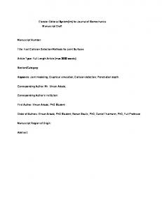
Figure 1: The simultaneous traversal of two BV hierarchies is, conceptually, equivalent to the traversal of a BV pairs hierarchy. Here, the right DOP tree is “tumbled” with respect to the DOP orientations of the left tree’s reference frame. traverse(A,B) if A and B do not overlap then return end if if A and B are leaves then return intersection of primitives encl. by A and B else for all children A[i] and B[j] do traverse(A[i],B[j]) end for end if
traverse(A,B,L) transform A transform B for all N ∈ L do if X and N do overlap then if X and N are leaves then check primitives enclosed by X and N else L0X + = N1 , N2 end if end if end for if A is an inner node then traverse(A1 , A2 ,L0A ) else traverse(A,L0A ) end if if B is an inner node then traverse(B1 , B2 ,L0B ) else traverse(B,L0B ) end if
Algorithm 1: The traditional traversal scheme. A[i] and B[j] are the child nodes of A and B, resp. For sake of clarity, the “mixed” cases (one node is a leaf, the other is not) are omitted. aligned nodes with which A needs to be checked for overlap. So we check all pairs (A, Li ); whenever such a pair overlaps, we append the two children Lij , j ∈ {1, 2}, to a new list L0 . After L has been completely processed, L0 contains all aligned nodes that need to be checked with A1 and A2 , the two children of A. It is obvious that with this traversal we visit each tumbled node only once, and thus we transform the DOP stored with it exactly once. This scheme works for all kinds of hierarchical collision detection, not just DOP trees. Depending on how much work per node-node overlap test can be factored out into one of the two nodes, the benefit of our new method can be dramatic. For example, considering Figure 1, a possible sequence of pairs of nodes could be: A1 B2 D4 E4 D5 E5 C2 F4 G4 F5 G5 B3 C3. This means, that with the classical traversal the sequence of node transformations is: 1 2 4 4 5 5 2 4 4 5 5. In contrast, with our new traversal scheme, this sequence of
Algorithm 2: The new algorithm scheme for hierarchical collision detection that transforms each tumbled DOP only once, and that reduces the number of multiple visits of nodes by a factor 2. Operations involving node “X” are performed for both nodes A and B. They can be executed in parallel. visited node pairs is: A1 B2 C2 D4 E4 F4 G4 D5 E5 F5 G5 B3 C3, and the sequence of node transformations is: 1 2 4 5 3. A hardware implementation allows us to improve the algorithm further by performing DOP overlap tests in parallel. We can exploit the fact that if two nodes A, B overlap, then we always need to check all children pairs (Ai , Bj ). Conse4
transformed into d0 in the coordinate frame of OB by
quently, instead of storing pointers to all children in the list L0 , we store only one pointer for each pair of siblings. By the nature of the binary tree, performing two overlap tests in parallel yields the greatest cost/performance benefit. To this end, we load a sibling pair of tumbled DOPs (A, B), transform them sequentially, and compare the two in parallel with each DOP from L. This results in two new lists, one for child pair (A1 , A2 ) and one for (B1 , B2 ). In the sequential version described in the previous paragraph, we produced these two lists at very different times during the traversal, and we processed each of them twice; now, we produce those two lists simultaneously, and then we process each of them only once. 1 The benefit of this is that the time needed for overlap tests and the number of times an axis-aligned DOP needs to be transferred from memory is cut by a factor of two. The pseudo-code in Algorithm 2 summarizes this new algorithm scheme. The traversal starts with list L initialized to the 4 pairs of first the level beneath the roots. Note that, for clarity, we have omitted the “mixed” cases. Note also that the last call of traverse is actually a call of an overloaded version, which has only slight differences from the algorithm shown here.
d0 = C × d + c where
... .. C= . ...
(1)
c0,0
...
c0,1
...
c0,2
...
ck−1,0
...
ck−1,1
...
ck−1,2
...
where in matrix C exactly three entries per row are non-zero. Second, d0 is compared componentwise with DOP e according to ∃i ≤
k 2
: di0 > e k +i ∨ ei > d0k +i 2
2
d and e do not overlap where di0 < d0k
2 +i
⇔
(2)
define a slab (analogously for all
DOPs). Matrix C and vector c depend only on the position of the two objects relative to each other. They are computed during the set-up by the software API of the collision detection hardware. Since the k × k-matrix C in Equation 1 has exactly 3 coefficients per row that are not 0, we can compute d0 more efficiently by
d ji,0 di0 = Ci d ji,1 + ci d ji,2
3.2 DOP overlap test The basic operation of any hierarchical collision detection algorithm is the overlap check of two nodes from different objects. In this section, we briefly recall the calculations necessary for collision detection using DOP trees. The derivation of the following formulas can be found in [19]. DOPs are bounding volumes that are a generalization of axis-aligned bounding boxes. They have been introduced into computer graphics by [8]. DOP trees are a hierarchical representation of objects [19, 9]. Each node stores a DOP and pointers to its children which it encloses; leaves store pointers to polygons instead of children. A DOP is described by k numbers (hence k-DOP ), usually represented by a vector of k floats. Extensive benchmarks have shown k = 24 to be optimal. Given two objects O A and OB , and two DOPs d, e ∈ Rk from O A and OB ’s DOP trees, resp., the overlap test, as presented in [19], proceeds in two steps: first, DOP d from O A ’s hierarchy is 1
,
(3)
where correspondence j stores the place of those coefficients which are not zero. So, by introducing a k × 3 correspondence matrix j, we can reduce the size of the transformation matrix C to k × 3. Consequently, the number of multiplications is 3k.
3.3 Polygon intersection test When the traversal reaches pairs of leaves (which containing triangles), a triangle-triangle intersection test has to be performed. In the following, we will briefly recall the calculations involved, which have already been described elsewhere [21]. The approach of our algorithm is to precompute a matrix MB that transforms B into the unit triangle, and then check (conceptually) each edge of A0 = A · M · MB against that unit triangle (and vice versa), where M is the transformation from O A into OB .
This scheme can be generalized straight-forward to process 2m tumbled nodes simultaneously.
5
z
A
P
Q
1
x
B 1
S
y
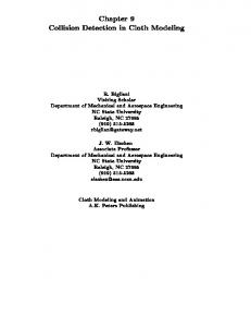
Figure 2: The improved traversal scheme can be implemented by a stack of lists. (In a hardware implementation, the stack on the right is merged into the left one.)
This basically amounts to the following calculations and tests per edge PQ of A0 :
Figure 3: Using a special transformation, the intersection test can be done very efficiently.
Memory for DOP Hierarchies and Triangle Data
Four−Bank DDR−SDRAM 256
Px Qz ≥ Q x Pz Py Qz ≥ Qy Pz
∧ ∧
Memory Controller
(4)
Px Qz − Q x Pz + Py Qz − Qy Pz ≤ Qz − Pz
Pointers Stack of Pointer Lists
256
The algorithm gains its special efficiency because we can precompute the matrices M A and MB (they can be obtained from a simple linear equation system), and because we do not need to compute the exact intersection point. In our case of collision detection using DOP trees, we can store these matrices in the leaves instead of the DOPs. We do not need to check pairs of leaf DOPs, because the immediate check of triangles is faster. Storing the triangle matrix MB and 3 vertices needs 3 × 4 + 3 × 3 = 21 floats, which fit well into the nodes of a 24-DOP tree.
DOP Unit
Over− lap Stack Flags Engine
Triangle Unit
Fast SRAM
Cache Hit / Miss
Intersection Flags PCI Interface
Pointers
Pointers Pointer FIFO
PCI−bus
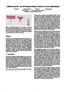
Figure 4: Block diagram of the CollisionChip and external Memory Systems.
4 Hardware Architecture The target design is a PCI-board with one ASIC (or FPGA), a large on-board memory for the hierarchies, and two SRAM devices as dedicated stack memory. Crucial for the performance is the bandwidth towards the local memory, and so a fourbank SDRAM configuration with a 256-bit bus was chosen. The proposed circuitry is a highperformance, massively parallel implementation of the algorithms described above. Figure 4 shows as major functional units Memory Controller, Stack Engine, DOP Unit, Triangle Unit and PCI Interface. The Stack Engine performs the novel traversal algorithm as described in Section 3 by creating and processing lists of node pointers. It maintains
6
these lists in two external fast SRAMs. Pointers are passed to the Memory Controller, which fetches the corresponding DOP-coefficients or triangle data from the SDRAM. The DOP-Unit performs the overlap test, while the Triangle Unit tests for triangle intersections. The identifiers of intersecting triangles are delivered to the software via a Pointer FIFO and the PCI Interface. We will explain all components in greater detail in the following sections.
4.1 DOP Unit The DOP Unit performs the DOP transformation for “tumbled” nodes as described in Section 3, and the overlap test with all the “aligned” nodes in the current list. A schematic drawing is shown in Fig-
Data Bus D 0..D 255
from Memory Controller
d0 ...
...
...
MUX
MUX
MUX
C0,n MC0 C1,n MC1
MUX
d23 d23
...
MUX
d23 d23
Matrix−and MUX−Control Memory
MUX
d1 d1
d1
32
...
24:1 32−bit MUX
Right Tumbled Node Pipeline
MUX
d0
Left Tumbled Node Pipeline
MUX
d1
d0
MUX
d0
Current / Next Node
... ...
...
...
MUX
MUX
MUX
...
C23,n MC23 5
128
dkC i,1+dmC i,2+dnC i,3+C i,4
dkC i,1+dmC i,2+dnC i,3+C i,4
2 DOTADD−Units Dual−Port Memory for transformed DOP−Pairs Next DOP−Pair Current DOP−Pair (thick border) Overlap / Logic No Overlap Function
Aligned DOP Coefficients
d’4
d’4
d’5
d’5
d’11 d’11
d’12 d’12 d’13 d’13 d’20 d’20 d’21 d’21 d’4
d’4
d’5
d’19 d’19
...
d’3
d’5
d’11 d’11 d’19 d’19
CMP
CMP
CMP
e0 e8 e16
e1 e9 e17
d’3
... CMP ...
Read
d’3
d’12 d’12 d’13 d’13 d’20 d’20 d’21 d’21 CMP
Write Address Enable Generator 8
Write
d’3
CMP
e7 e15 e23
16 parallel FP−Compare Units 256
Figure 5: The DOP Unit checks pairs of DOPs for overlap. It has a throughput of two pairs every 4 cycles. ure 5. As explained above, the algorithm always processes pairs (siblings) of tumbled nodes. Thus, there is one processing pipeline for the right (gray units) and one for the left sibling. Prior to the processing of two hierarchies, the matrix C and a set of multiplexer control bits (MC) must be loaded into the on-chip Matrix- and MUX-Control Memory (MMM). Once a pair of DOPs has been loaded into the two vertical register sets, transformation starts, under control of an Address Generator. This unit cycles through the MMM, which causes the proper sets of matrix elements and DOP coefficients to appear at the inputs of two so-called DOTADDunits. These pipelined units basically compute one dot product. They produce one DOP coefficient d0 per clock, which are then written pairwise into a
dual-port memory, which stores 8 pairs in one entry. Once a tumbled DOP pair has been transformed, overlap check against all the aligned DOPs in the current list will be started. Since the on-chip data bus is 256 bits wide, the aligned node coefficients e will appear in bundles of eight. Each bundle is compared to the corresponding set of coefficients d0 (note the dual-port memory layout), using a bank of 16 floating-point compare units. The overlap flags are then passed to the Stack Engine. Given the maximum overall data transfer rate, an overlap test of one aligned DOP against two tumbled DOPs takes a minimum of 4 clock cycles. Once a tumbled DOP pair has been loaded from memory, however, the memory would be idle during the transformation. We exploit this by prefetching the two child DOPs of the left parent DOP, and
7
Pointer to "Aligned" Triangle Data
Cache Hit/Miss
2−line RAM for "Tumbled" Triangle Data Cache Index
S1,1 ... S3,4 Px Qx Rx Py Qy Ry Pz Qz Rz TAG MUX Ay
MUX Az
M 1,1..1,4 FIFO
M2
T1 * A ’
T2
*A
M3
N 1,1..1,4
*A A’z
T3
P’’y, Q’’y, R’’y Intersection Test Unit A
MUX Bx
M 3,1..3,4
A’y
* A’
Px Qx Rx Py Qy Ry Pz Qz Rz T1,1 ... T3,4
=
M 2,1..2,4
M1 * A A’x
R’’x Q’’x P’’x
Data Bus D0 .. 255
Hash− Function
Cache for "Aligned" Triangle Data
MUX Ax
Left/Right Tumbled Node
Hierarchy Path
* A’ R’’z Q’’z P’’z
MUX Bz
N 2,1..2,4
N1 * B B’x
N2
S1 * B ’
S2
R’’x Q’’x P’’x
MUX By
*B
N 3,1..3,4 N3
B’y
* B’
*B
FIFO
B’z
S3
P’’y, Q’’y, R’’y Intersection Test Unit B
* B’ R’’z Q’’z P’’z
Intersection / No Intersection
Figure 6: The first stage of the Triangle Unit transforms pairs of triangles. Only on the left side a small cache of about 11 kB is needed. by transforming these coefficients speculatively during processing of the following list. Thus, the number of input registers holding d must be doubled as well as the memory capacity to store d0 . In Figure 5, the two sets of storage elements are distinguished by thick or thin borders. It should also be clear why a dual-port memory is needed for the coefficients d0 : while a set of 16 coefficients is read for overlap test, two transformed coefficients of the children are written. The concept of hiding the DOP transformation behind the overlap tests is used whenever possible. This means that the children of the left parent in the tumbled hierarchy are loaded and transformed as soon as the required resources are available. If the lists are long enough, processing of tumbled DOPs is hidden except for the memory read. Only in case there are no overlaps in a given list (and so no new lists are generated), an initial latency will occur. This initial latency is estimated to be 64 clock cycles, starting from the point when the node pointer is fetched from the SRAM and ending with two transformed DOPs being present in the dual-port memory. Unfortunately, an efficient cache architecture for the DOP unit has yet to be found. All our simulations revealed a very low spatial and temporal coherence in the DOP access pattern. Hit rates above 80% can only be achieved with large cache sizes (>256KBytes), independent of index func-
tion or cache associativity. Likewise, using Page Interleaving and Page Mode Accesses do not improve the perfomance significantly.
4.2 Stack Engine The Stack Engine processes a list by sequentially reading the DOP pointers in the list from the SRAM, and passing each pointer to the Memory Controller. This unit returns, along with the DOP pair, two child pointers to the Stack Engine. In case the parents are tumbled DOPs, these two pointers form the heads of two new lists and are written into the two SRAM chips. In case the parents are aligned DOPs, the Stack Engine evaluates the overlap flags and appends each pointer to the corresponding list, or discards it accordingly. When the list is done, the Stack Engine recurses on the next lower level. By default, the “left” branch is taken. If the left list is empty, the right list is used. If this list is empty too, the Stack Engine steps up one level in the hierarchy. Internally, the Stack Engine maintains a stack of list pointers, one for each hierarchy level and branch, and a register containing the actual hierarchy level λ. Reads refer to level λ, writes to λ + 1. Since the lists are of varying length, but written contiguously into the SRAMs, there are additional marker registers defining the start of each list. Each SRAM chip is dedicated to either the left or the right list. 8
From DOTADD−Units on second Stage
P’’x
P’’y
P’’z
MUX
MUX
Q’’x
MUX
FPMUL
Q’’y
MUX
Q’’z
MUX
FPMUL
MUX
R’’y
R’’z
MUX
MUX
FPMUL
FPSUB
FPMUL
MUX
MUX
FPSUB
FIFO
FPSUB
>0, 0,