High performance GaN-based LEDs on patterned sapphire substrate with patterned composite SiO 2/Al 2 O 3 passivation layers and TiO 2 /Al 2O 3 DBR backside reflector Hao Guo,1, 2 Xiong Zhang, 1,* Hongjun Chen,1 Peiyuan Zhang,1 Honggang Liu, 2 Hudong Chang, 2 Wei Zhao, 2 Qinghua Liao,3 and Yiping Cui 1 1
Advanced Photonics Center, School of Electronic Science and Engineering, Southeast University, Nanjing 210096, China Microwave Device and IC Department, Institute of Microelectronics, Chinese Academy of Sciences, Beijing 100029, China 3 Department of Physics, Nanchang University, Nanchang 330031, China *
[email protected]
2
Abstract: GaN-based light-emitting diodes (LEDs) on patterned sapphire substrate (PSS) with patterned composite SiO 2 /Al 2 O 3 passivation layers and TiO 2 /Al 2 O 3 distributed Bragg reflector (DBR) backside reflector have been proposed and fabricated. Highly passivated Al 2 O 3 layer deposited on indium tin oxide (ITO) layer with excellent uniformity and quality has been achieved with atomic layer deposition (ALD) technology. With a 60 mA current injection, an enhancement of 21.6%, 59.7%, and 63.4% in the light output power (LOP) at 460 nm wavelength was realized for the LED with the patterned composite SiO 2 /Al 2 O 3 passivation layers, the LED with the patterned composite SiO 2 /Al 2 O 3 passivation layers and Ag mirror + 3-pair TiO 2 /SiO 2 DBR backside reflector, and the LED with the patterned composite SiO 2 /Al 2 O 3 passivation layer and Ag mirror + 3-pair ALDgrown TiO 2 /Al 2 O 3 DBR backside reflector as compared with the conventional LED only with a single SiO 2 passivation layer, respectively. ©2013 Optical Society of America OCIS codes: (230.0230) Optical devices; (230.3670) Light-emitting diodes; (230.1480) Bragg reflectors; (250.0250) Optoelectronics.
References and links 1.
N. Shibata, T. Uemura, H. Yamaguchi, and T. Yasukawa, “Fabrication of LED based on III-V nitride and its applications,” Phys. Status Solidi, A Appl. Res. 200(1), 58–61 (2003). 2. A. I. Zhmakin, “Enhancement of light extraction from light emitting diodes,” Phys. Rep. 498(4–5), 189–241 (2011). 3. J. J. Wierer, A. David, and M. M. Megens, “III-nitride photonic-crystal light-emitting diodes with high extraction efficiency,” Nat. Photonics 3(3), 163–169 (2009). 4. M. K. Kwon, J. Y. Kim, I. K. Park, K. S. Kim, G. Y. Jung, S. J. Park, J. W. Kim, and Y. C. Kim, “Enhanced emission efficiency of GaN/ InGaN multiple quantum well light-emitting diode with an embedded photonic crystal,” Appl. Phys. Lett. 92(25), 251110 (2008). 5. K. Kim, J. Choi, J. B. Park, S. C. Jeon, J. S. Kim, and H. M. Lee, “Lattice constant effect of photonic crystals on the light output of blue light-emitting diodes,” IEEE Photon. Technol. Lett. 20(17), 1455–1457 (2008). 6. Y. W. Cheng, S. C. Wang, Y. F. Yin, L. Y. Su, and J. J. Huang, “GaN-based LEDs surrounded with a twodimensional nanohole photonic crystal structure for effective laterally guided mode coupling,” Opt. Lett. 36(9), 1611–1613 (2011). 7. Y. J. Lee, H. C. Kuo, T. C. Lu, B. J. Su, and S. C. Wang, “Fabrication and characterization of GaN-based LEDs grown on chemical wet-etched patterned sapphire substrates,” J. Electrochem. Soc. 153(12), G1106–G1111 (2006). 8. Y. J. Lee, H. C. Kuo, T. C. Lu, S. C. Wang, K. W. Ng, K. M. Lau, Z. P. Yang, A. Chang, and S. Y. Lin, “Study of GaN-based light-emitting diodes grown on chemical wet-etching-patterned sapphire substrate with V-shaped pits roughening surfaces,” J. Lightwave Technol. 26(11), 1455–1463 (2008). 9. J. J. Chen, Y. K. Su, C. L. Lin, S. M. Chen, W. L. Li, and C. C. Kao, “Enhanced output power of GaN-based LEDs with nano-patterned sapphire substrates,” IEEE Photon. Technol. Lett. 20(13), 1193–1195 (2008). 10. T. S. Oh, Y. S. Lee, H. Jeong, J. D. Kim, T. H. Seo, and E. K. Suh, “Characteristics of GaN-based light emitting
#191768 - $15.00 USD Received 5 Jun 2013; revised 31 Jul 2013; accepted 13 Aug 2013; published 5 Sep 2013 (C) 2013 OSA 9 September 2013 | Vol. 21, No. 18 | DOI:10.1364/OE.21.021456 | OPTICS EXPRESS 21456
11. 12. 13. 14. 15. 16. 17. 18.
19. 20. 21. 22. 23. 24. 25.
26. 27. 28. 29. 30. 31. 32. 33. 34.
diode grown on circular convex patterned sapphire substrate,” Phys. Status Solidi., C Curr. Top. Solid State Phys. 6(2), 589–592 (2009). J. H. Lee, D. Y. Lee, B. W. Oh, and J. H. Lee, “Comparison of InGaN-Based LEDs Grown on Conventional Sapphire and Cone-Shape-Patterned Sapphire Substrate,” IEEE Trans. Electron. Dev. 57(1), 157–163 (2010). Y. F. Li, S. You, M. W. Zhu, L. Zhao, W. T. Hou, T. Detchprohm, Y. Taniguchi, N. Tamura, S. Tanaka, and C. Wetzel, “Defect-reduced green GaInN/GaN light-emitting diode on nanopatterned sapphire,” Appl. Phys. Lett. 98(15), 151102 (2011). H. Kim, K. K. Choi, K. K. Kim, J. Cho, S. N. Lee, Y. Park, J. S. Kwak, and T. Y. Seong, “Light-extraction enhancement of vertical-injection GaN-based light-emitting diodes fabricated with highly integrated surface textures,” Opt. Lett. 33(11), 1273–1275 (2008). B. Sun, L. X. Zhao, T. B. Wei, X. Y. Yi, Z. Q. Liu, G. H. Wang, J. M. Li, and F. T. Yi, “Light extraction enhancement of bulk GaN light-emitting diode with hemisphere-cones-hybrid surface,” Opt. Express 20(17), 18537–18544 (2012). Y. H. Jin, F. L. Yang, Q. Q. Li, Z. D. Zhu, J. Zhu, and S. S. Fan, “Enhanced light extraction from a GaN-based green light-emitting diode with hemicylindrical linear grating structure,” Opt. Express 20(14), 15818–15825 (2012). S. Kim, S. M. Kim, H. H. Park, D. G. Choi, J. W. Jung, J. H. Jeong, and J. R. Jeong, “Conformally direct imprinted inorganic surface corrugation for light extraction enhancement of light emitting diodes,” Opt. Express 20(S5 Suppl 5), A713–A721 (2012). T. Fujii, Y. Gao, R. Sharma, E. L. Hu, S. P. DenBaars, and S. Nakamura, “Increase in the extraction efficiency of GaN-based light-emitting diodes via surface roughening,” Appl. Phys. Lett. 84(6), 855–857 (2004). B. J. Kim, H. Jung, J. Shin, M. A. Mastro, C. R. Eddy, Jr., J. K. Hite, S. H. Kim, J. Bang, and J. Kim, “Enhancement of light extraction efciency of ultraviolet light emitting diodes by patterning of SiO 2 nanosphere arrays,” Thin Solid Films 517(8), 2742–2744 (2009). J. Y. Cho, K. J. Byeon, and H. Lee, “Forming the graded-refractive-index antireflection layers on light-emitting diodes to enhance the light extraction,” Opt. Lett. 36(16), 3203–3205 (2011). K. M. Chang, C. C. Lang, and C. C. Cheng, “The silicon nitride film formed by ECR-CVD for GaN-based LED passivation,” Phys. Status Solidi, A Appl. Res. 188(1), 175–178 (2001). X. L. Da, X. Guo, L. M. Dong, Y. P. Song, W. W. Ai, and G. D. Shen, “The silicon oxynitride layer deposited at low temperature for high-brightness GaN-based light-emitting diodes,” Solid-State Electron. 50(3), 508–510 (2006). G. D. Shen, X. L. Da, X. Guo, Y. X. Zhu, and N. H. Niu, “Effects of the passivation layer deposition temperature on the electrical and optical properties of GaN-based light-emitting diodes,” J. Lumin. 127(2), 441–445 (2007). Y. K. Su, H. C. Wang, C. L. Lin, W. B. Chen, and S. M. Chen, “Improvement of AlGaInP light emitting diode by sulfide passivation,” IEEE Photon. Technol. Lett. 15(10), 1345–1347 (2003). S. J. So and C. B. Park, “Improvement of brightness with Al 2 O 3 passivation layers on the surface of InGaN/GaN-based light-emitting diode chips,” Thin Solid Films 516(8), 2031–2034 (2008). C. H. Lin, C. F. Lai, T. S. Ko, H. W. Huang, H. C. Kuo, Y. Y. Hung, K. M. Leung, C. C. Yu, R. J. Tsai, C. K. Lee, T. C. Lu, and S. C. Wang, “Enhancement of InGaN-GaN indium-tin-oxide flip-chip light-emitting diodes with TiO 2 -SiO 2 multilayer stack omnidirectional reflector,” IEEE Photon. Technol. Lett. 18(19), 2050– 2052 (2006). H. W. Huang, H. C. Kuo, C. F. Lai, C. E. Lee, C. W. Chiu, T. C. Lu, S. C. Wang, C. H. Lin, and K. M. Leung, “High-performance GaN-based vertical-injection light-emitting diodes with TiO 2 -SiO 2 omnidirectional reflector and n-GaN roughness,” IEEE Photon. Technol. Lett. 19(8), 565–567 (2007). S. J. Chang, C. F. Shen, M. H. Hsieh, C. T. Kuo, T. K. Ko, W. S. Chen, and S. C. Shei, “Nitride-based LEDs with a hybrid Al mirror+TiO 2 /SiO 2 DBR backside reector,” J. Lightwave Technol. 26(17), 3131–3136 (2008). N. M. Lin, S. C. Shei, and S. J. Chang, “Nitride-based LEDs with high-reflectance and wide-angle Ag mirror +SiO 2 /TiO 2 DBR backside reflector,” J. Lightwave Technol. 29(7), 1033–1038 (2011). W. C. Lee, S. J. Wang, K. M. Uang, T. M. Chen, D. M. Kuo, P. R. Wang, and P. H. Wang, “Enhanced light output of vertical-structured GaN-based light-Emitting Diodes with TiO 2 /SiO 2 Reflector and roughened GaO x surface film,” Jpn. J. Appl. Phys. 50(4), 04DG06 (2011). B. Zhang, Z. S. Zhang, J. Xu, Q. Ren, C. L. Jin, Z. J. Yang, Q. Wang, W. H. Chen, X. D. Hu, T. J. Yu, Z. X. Qin, G. Y. Zhang, D. P. Yu, and B. P. Zhang, “Effects of the artificial Ga-nitride/air periodic nanostructures on current injected GaN-based light emitters,” Phys. Status Solidi C 2(7), 2858–2861 (2005). R. Sharma, E. D. Haberer, C. Meier, E. L. Hu, and S. Nakamura, “Vertically oriented GaN-based air-gap distributed Bragg reflector structure fabricated using band-gap-selective photoelectrochemical etching,” Appl. Phys. Lett. 87(5), 051107 (2005). R. Sharma, Y. S. Choi, C. F. Wang, A. David, C. Weisbuch, S. Nakamura, and E. L. Hu, “Gallium-nitride-based microcavity light-emitting diodes with air-gap distributed Bragg reflectors,” Appl. Phys. Lett. 91(21), 211108 (2007). A. Altoukhov, J. Levrat, E. Feltin, J.-F. Carlin, A. Castiglia, R. Butté, and N. Grandjean, “High reflectivity airgap distributed Bragg reflectors realized by wet etching of AlInN sacrificial layers,” Appl. Phys. Lett. 95(19), 191102 (2009). J. H. Ryu, H. Y. Kim, H. K. Kim, Y. S. Katharria, N. Han, J. H. Kang, Y. J. Park, M. Han, B. D. Ryu, K. B. Ko, E. K. Suh, and C. H. Hong, “High performance of InGaN light-emitting diodes by air-gap/GaN distributed Bragg reflectors,” Opt. Express 20(9), 9999–10003 (2012).
#191768 - $15.00 USD Received 5 Jun 2013; revised 31 Jul 2013; accepted 13 Aug 2013; published 5 Sep 2013 (C) 2013 OSA 9 September 2013 | Vol. 21, No. 18 | DOI:10.1364/OE.21.021456 | OPTICS EXPRESS 21457
35. T. C. Lu, T. T. Kao, C. C. Kao, J. T. Chu, K. F. Yeh, L. F. Lin, Y. C. Peng, H. W. Huang, H. C. Kuo, and S. C. Wang, “GaN-based high-Q vertical-cavity light-emitting diodes,” IEEE Electron Device Lett. 28(10), 884– 886 (2007). 36. S. Fernández, F. B. Naranjo, F. Calle, M. A. Sánchez-García, E. Calleja, P. Vennegues, A. Trampert, and K. H. Ploog, “High-quality distributed Bragg reflectors based on AlxGa1−xN/GaN multilayers grown by molecular-beam epitaxy,” Appl. Phys. Lett. 79(14), 2136 (2001). 37. D. Byrne, F. Natali, B. Damilano, A. Dussaigne, N. Grandjean, and J. Massies, “Blue resonant cavity light emitting diodes with a high-Al-content GaN/AlGaN distributed Bragg reflector,” Jpn. J. Appl. Phys. 42(Part 2, No. 12B), L1509–L1511 (2003). 38. H. Liu, H. Zhao, J. Hou, D. Liu, and Y. H. Gao, “Enhanced light extraction in AlInGaN UV light-emitting diodes by an embedded AlN/AlGaN distributed Bragg reflector,” Chin. Phys. Lett. 29(10), 108501 (2012).
1. Introduction High-efficiency GaN-based light-emitting diodes (LEDs) with emission wavelength varied from ultraviolet (UV) to visible range, have received considerable attention as a potential light source in solid-state lightings for general illumination [1]. However, the light extraction efficiency (LEE) of GaN-based LEDs remains low because of the so-called total internal reflection (TIR) that takes place at the hetero-interface between the LED surface and air [2]. Considering the refractive indices of GaN and air, the critical angle θ c for TIR is as small as 24.6° [3]. This small θ c hinders the light extraction seriously, as most of the light beams with an incident angle larger than θ c will be reflected back to the LED and eventually absorbed by the GaN-based epitaxial layers. Therefore, several recent studies have focused on improving the LEE by changing light beam trajectories using various kinds of approaches, such as integration of two-dimensional photonic crystal structures [4–6], preparation of patterned sapphire substrate (PSS) [7–12], and control of surface textures [13–17]. In recent years, to improve the optical and electrical performances of the LEDs, some innovative designs of the structural parameters for the surface and backside of the LEDs have been reported [18–38]. As some examples, GaN-based LEDs with SiO 2 [18, 19], SiN x [20] and SiON x [21, 22] passivation layers have been investigated to enhance the light output power (LOP). In order to increase luminous intensity, ammonia sulfide was used to passivate the perimeter of AlGaInP LEDs by Su et al. [23]. So and his associates [24] proposed to deposit an Al 2 O 3 passivation layer on the surface of InGaN/GaN-based LED chips to enhance the brightness of LED lamps. On the other hand, adding a backside reñector beneath the substrate had been demonstrated to be an effective method to reflect those originally downward-going photons going upward and thus to increase the LOP [25–38]. In particular, GaN-based LEDs with TiO 2 /SiO 2 distributed Bragg reflector (DBR) and metallic mirrors have been reported [25–29]. The air-gap DBR structure in LEDs, which acts as a light reflector to redirect light into the escape cones on both front and back sides of the LEDs, has also been developed [30–34]. By using DBR reflectors made of AlN, GaN, and AlGaN, highefficiency LEDs with emission wavelength varied from UV to visible range have been realized [35–38]. In this work, we report high performance GaN-based LEDs grown on PSS with the patterned composite SiO 2 /Al 2 O 3 passivation layers and TiO 2 /Al 2 O 3 DBR backside reflector. With the help of atomic layer deposition (ALD) technology, highly passivated Al 2 O 3 layer with excellent uniformity and quality has been achieved. Due to the selective etching characteristic of SiO 2 and Al 2 O 3 , the etching process of SiO 2 layer with the fluorine-based etching gases would end on the surface of Al 2 O 3 layer underneath and would not cause any damage to indium tin oxide (ITO) or p-GaN layer. The SiO 2 layer with patterned hemisphere arrays creates an ensemble of extra light-exiting angles that is powerful in decreasing the TIR effect and hence increasing the LOP. The DBR made by ALD process has been shown to have better quality than that made by electron beam evaporation (EBE), and the ALD process time is nearly the same as the EBE process or even less. Moreover, to grow a DBR composed of at least two or more kinds of materials, it is generally necessary to raise and lower the temperature frequently in the EBE process whereas the temperature can be maintained the same in the ALD process for depositing different materials. Furthermore, due to the good
#191768 - $15.00 USD Received 5 Jun 2013; revised 31 Jul 2013; accepted 13 Aug 2013; published 5 Sep 2013 (C) 2013 OSA 9 September 2013 | Vol. 21, No. 18 | DOI:10.1364/OE.21.021456 | OPTICS EXPRESS 21458
adhesion between the TiO 2 /Al 2 O 3 DBR and the metal mirror, the fabrication process was simplified and a more reliable backside reflector was achieved. 2. Experiments The GaN-based LEDs in this study were grown by metal organic chemical vapor deposition (MOCVD) on the C-plane (0001) 2-inch-diameter wafer with the specially designed PSS. The MOCVD growth process for the GaN-based LEDs on PSS is as follows. First of all, a 3.2 μmthick photo-resist film was coated on the flat sapphire substrate. Then, standard photolithography was used to create patterns on the photo-resist film. The sapphire substrate was subsequently etched by using inductively coupled plasma (ICP) with Cl 2 as the reactive gas. The base diameter for each pattern and the interval between patterns are 3.6 μm and 6.4 μm, respectively. The height of the pattern is approximately 1.1 μm. The GaN-based LED structure grown on PSS consists of a 30 nm-thick GaN buffer layer, a 4.5 μm thick n-type GaN:Si layer, six pairs of InGaN/GaN multiple quantum wells (MQWs) active layers, and a 0.9 μm-thick p-type GaN:Mg layer. A 240 nm-thick ITO layer was deposited on the LED top surface to serve as the transparent contact layer. Cr/Pt/Au contact was evaporated onto the surface of ITO layer as the p electrode and onto the surface of the exposed n-type GaN:Si layer as the n electrode.
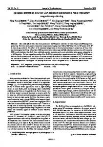
Fig. 1. (a) Schematic diagram of LED layer structure grown on PSS with the patterned composite SiO 2 /Al 2 O 3 passivation layers and TiO 2 /Al 2 O 3 DBR backside reflector. (b) The cross-sectional view scanning electron microscopy (SEM), images for the fabricated LED. The domain view of the patterned composite SiO 2 /Al 2 O 3 passivation layers and PSS is on the upper right, and the domain view of the DBR is on the lower right.
Firstly, to evaluate the influence of the passivation layers on the electrical and optical performances of the GaN-based LEDs, four LED samples passivated respectively with an ALD-grown Al 2 O 3 layer, an EBE-grown Al 2 O 3 layer, a plasma-enhanced chemical vapor deposition (PECVD)-grown SiN x layer, and a PECVD-grown SiO 2 layer were fabricated. The ALD-grown Al 2 O 3 layer could be made to cover the whole surface of the LED except for the n- and p-type contact areas, including the side-wall surface of the MQWs active region exposed after ICP etching. Secondly, in order to improve the electrical and optical performances of GaN-based LEDs, novel patterned composite SiO 2 /Al 2 O 3 passivation layers consisting of two dielectric stack layers, SiO 2 and Al 2 O 3 , were proposed and developed in this study. As shown in Fig. 1, the Al 2 O 3 layer acts as an effective surface passivation layer and the SiO 2 layer with patterned hemisphere arrays creates an ensemble of extra light-exiting angles to decrease the TIR and hence to increase the LOP. Six GaN-based LED samples with different passivation structures (but without DBR backside reflector) were fabricated and analyzed. For fabricating
#191768 - $15.00 USD Received 5 Jun 2013; revised 31 Jul 2013; accepted 13 Aug 2013; published 5 Sep 2013 (C) 2013 OSA 9 September 2013 | Vol. 21, No. 18 | DOI:10.1364/OE.21.021456 | OPTICS EXPRESS 21459
the patterned composite SiO 2 /Al 2 O 3 passivation layers, at first a modified cleaning technology was used to remove residual contaminants on both sides of the wafers with HCl and HF acids to obtain clean surfaces with reduced roughness. Then, the double dielectric stack layers that are consisted of a 10 nm-thick Al 2 O 3 layer deposited by ALD and a 500 nmthick SiO 2 layer deposited by PECVD, were sequentially grown on the surface of the LED to complete the preliminary fabrication process of the passivation layers. Next, a positive photoresist film with a thickness of 1 μm was coated on the SiO 2 film and exposed with a Nikon stepper 1755i7A to form the triangularly patterned array which was used as the soft etching mask. Here the diameter of the patterns is 2 μm and the spacing between the patterns is 1 μm. After development, the so-called photoresist reflow method was adopted to form the hemispherical photo-resist pattern. The photoresist reflow process is associated with the melting characteristic of the photo-resist islands. When the photoresist islands are melted, the fluid photoresist surfaces are pulled into such a shape that the surface energy of the fluid is minimized. It was found that the reflow temperature and time played the key roles in determining the shape of photoresist island pattern. When the photoresist film was baked for longer reflow time or at higher reflow temperature, the base diameter of hemisphere is larger, and the height of hemisphere is lower. ICP etching technology was utilized to transfer the hemispherical patterns to the SiO 2 layer. As the CHF 3 /O 2 gas ratio was 40:15, the etching selectivity was 1:1.1, or the etching rates for both SiO 2 and O 2 were nearly the same. At such an etching condition, the patterns on the photo-resist soft mask were successfully transferred to the SiO 2 hard mask layer without distorting the original surface profile. Finally, to further enhance the LOP of the LEDs, a TiO 2 /Al 2 O 3 DBR reflector was added to the backside surfaces of the lapped and polished PSS by ALD technology. Trimethylaluminium (TMA) and water vapor (H 2 O) were used as the chemical precursors to grow Al 2 O 3 film. On the other hand, TiCl 4 and H 2 O were used as precursors to grow TiO 2 film. The precursors were alternatively fed into the reactor using pure N 2 as the carrier gas. Both Al 2 O 3 and TiO 2 films were grown at a fixed temperature of 250 °C so that the fabricating time was saved and high quality TiO 2 /Al 2 O 3 DBR reflector was achieved. In order to avoid gas phase pre-reactions caused by intermixing of the precursors, the reactor was purged with pure N 2 gas after each precursor-feeding pulse. A complete growth cycle consists of 100 ms pulse of TMA or TiCl 4 , 1.5 s purge pulse of N 2 , 100 ms pulse of water vapor, and 1.5 s purge pulse of N 2 . After the DBR growth, a 100 nm-thick Al or Ag mirror was deposited onto the DBR surface by EB deposition process to further enhance the reflectivity of the backside reflector. 10 nm-thick Ni film was also deposited onto the surface of Ag mirror to prevent the formation of silver sulfide. The thickness for each TiO 2 (n = 2.5) layer and each Al 2 O 3 (n = 1.6) layer in the TiO 2 /Al 2 O 3 DBR reflector was kept at 49 and 67 nm, respectively. Current-voltage (I-V) and LOP measurements of the LED chips were performed by FitTech IPT6000 LED chip/wafer probing and testing system. And a spectroscopic ellipsometry (SE) system [HORIBA-JY UVISEL] was employed to measure the reflectivity of the fabricated backside reflectors. MATLAB software was used to simulate the reflectivity of DBR. The measured refractive index of TiO 2 and Al 2 O 3 were used to improve the accuracy of simulation. And a microwave probe station was employed to measure the reverse leakage current, I R for the fabricated LEDs. To characterize the electro-static discharge (ESD) endurance of the LEDs, we applied negative ESD bias onto the LED chips up to 2000 V using the human body mode (HBM). After each test, a reverse bias of −5 V was applied to the LED chips and if the leakage current was larger than 5 μA, the LED chip was considered to be failed. The ESD yield is defined as the number of LED chips passing the test divided by the total number of LED chips tested. 3. Results and discussion As can be seen in Table 1, the GaN-based LED with a PECVD-grown SiO 2 passivation layer has the highest LOP, meanwhile it has the largest leakage current or the worst passivation effect. In contrast, the LED with an ALD-grown Al 2 O 3 passivation layer exhibits the best #191768 - $15.00 USD Received 5 Jun 2013; revised 31 Jul 2013; accepted 13 Aug 2013; published 5 Sep 2013 (C) 2013 OSA 9 September 2013 | Vol. 21, No. 18 | DOI:10.1364/OE.21.021456 | OPTICS EXPRESS 21460
passivation effect and decent LOP. The reason for this result is because the ALD technology offers excellent uniformity, great control capability, and high accuracy in layer thickness. In other words, the quality of ALD-made Al 2 O 3 film is the best within the four LED samples with various kinds of single passivation layer whereas the ALD process time is nearly the same as EBE process or even less. Table 1. Summary of the electrical and optical performances for the LEDs with an ALDgrown Al 2 O 3 passivation layer, an EBE-grown Al 2 O 3 passivation layer, a PECVD-grown SiN x passivation layer, and a PECVD-grown SiO 2 passivation layer, respectively. Performance
ALD-grown Al 2 O 3
EBE-grown Al 2 O 3
PECVD-grown SiN x
PECVD-grown SiO 2
LOP at 60 mA (mW)
42.7
43.6
38.2
45.4
I R at −5V (A)
−9.3 × 10⁻¹⁰
−7.6 × 10⁻⁹
−6.8 × 10⁻⁸
−1.8 × 10⁻⁷
Moreover, as shown in Fig. 1(a), since the side-wall surface of the LED chip could be covered with the Al 2 O 3 film by ALD, the leakage current and the probability of nonradiative recombination through the surface trap could be significantly reduced, and the radiative recombination efðciency in the MQWs active region near the side-wall edge could be effectively increased. The cross-sectional view SEM image for a typical fabricated GaNbased LED with patterned composite SiO 2 /Al 2 O 3 passivation layers and TiO 2 /Al 2 O 3 DBR backside reflector is shown in Fig. 1(b). After scribing and breaking the wafers into the LED chips, Ag or Al film was found to be partially lifted off from the conventional Ag + TiO 2 /SiO 2 DBR or Al + TiO 2 /SiO 2 DBR reflector, whereas the Ag or Al film on the Ag + TiO 2 /Al 2 O 3 DBR or Al + TiO 2 /Al 2 O 3 DBR reflector was not lifted off. Table 2. The detailed reflow conditions and etched surface profile parameters for the patterned composite SiO 2 /Al 2 O 3 passivation layers. Reflow temperature (degrees Celsius)
Reflow time (min)
Hemisphere height (nm)
Hemisphere base diameter (μm)
A
0
0
491
1.56
B
160
3
487
1.56
Sample
C
160
5
476
1.58
D
160
7
456
1.63
E
160
9
347
1.69
F
160
11
205
1.86
Table 2 summarizes the detailed reflow conditions and etched surface profile parameters for the patterned composite SiO 2 /Al 2 O 3 passivation layers.
#191768 - $15.00 USD Received 5 Jun 2013; revised 31 Jul 2013; accepted 13 Aug 2013; published 5 Sep 2013 (C) 2013 OSA 9 September 2013 | Vol. 21, No. 18 | DOI:10.1364/OE.21.021456 | OPTICS EXPRESS 21461
Fig. 2. The cross-sectional (upper) and top view (below) SEM images for the six LED samples with different patterned composite SiO 2 /Al 2 O 3 passivation layers, denoted as sample A (a), B (b), C (c), D (d), E (e), and F (f), respectively.
Fig. 3. (a) The microscope image for a typical GaN-based LED chip in our study with a size of 300 μm × 700 μm; (b) the microscope images for both p-electrode and n-electrode before and after wet etching.
Figures 2(a)-2(f) show the cross-sectional (upper) and top-view (below) SEM images for the six LED samples with different types of patterned composite SiO 2 /Al 2 O 3 passivation layers fabricated under different reflow conditions. The LEDs made with 0, 3, 5, 7, 9, and 11 min-reflow process are denoted as samples A, B, C, D, E, and F, respectively. It was noted that at a constant reflow temperature, the base diameter of hemisphere increased and the #191768 - $15.00 USD Received 5 Jun 2013; revised 31 Jul 2013; accepted 13 Aug 2013; published 5 Sep 2013 (C) 2013 OSA 9 September 2013 | Vol. 21, No. 18 | DOI:10.1364/OE.21.021456 | OPTICS EXPRESS 21462
height of hemisphere decreased when the reflow time was increased. Figure 3(a) shows the photograph taken with a microscope for a typical LED chip fabricated with a size of 300 μm × 700 μm in our study. By means wet-etching technology, the patterned composite SiO 2 /Al 2 O 3 passivation layers on the surfaces of both p-electrode and n-electrode were then removed with HF acid without any damage to the electrodes, as shown in Fig. 3(b). Table 3. The electrical and optical performances of the LED samples A, B, C, D, E, F, and the reference sample only with a single SiO 2 passivation layer. Sample
A
B
C
D
E
F
Reference
LOP at 60mA (mW)
49.2
49.6
52.9
53.5
55.2
50.9
45.4
I R at −5V (A)
−9
−1.1 × 10
−1.8 × 10−7
Table 3 shows the electrical and optical performances of the LED samples A, B, C, D, E, F, and the reference sample only with a single SiO 2 passivation layer. It is clear from Table 3 that the highest LOP was achieved with sample E in which the height and base diameter of the SiO 2 hemispheres is 350 nm and 1.7 μm, respectively. On the other hand, the leakage current I R was identical (~1.1 × 10⁻⁹ A at −5 V reverse bias) for all the six LED samples with the patterned composite SiO 2 /Al 2 O 3 passivation layers, which is, however, at least two orders lower in magnitude as compared with that of the reference sample (1.8 × 10⁻⁷ A at −5 V reverse bias). Therefore, sample E was identified as the baseline sample with the patterned composite SiO 2 /Al 2 O 3 passivation layers to fabricate the LEDs with the backside reflector added.
Fig. 4. (a) I-V characteristics and (b) EL spectra for the six LED samples fabricated in this study.
Figure 4(a) shows I-V characteristics for the LED only with 9 min-reflow patterned composite SiO 2 /Al 2 O 3 passivation layers (sample E), the LED with 9 min-reflow patterned composite SiO 2 /Al 2 O 3 passivation layers and Al mirror + 3-pair TiO 2 /SiO 2 DBR backside reflector (sample G), the LED with 9 min-reflow patterned composite SiO 2 /Al 2 O 3 passivation layers and Al mirror + 3-pair ALD-grown TiO 2 /Al 2 O 3 DBR (sample H), the LED with 9 min-reflow patterned composite SiO 2 /Al 2 O 3 passivation layers and Ag mirror + 3-pair TiO 2 /SiO 2 DBR (sample I), the LED with 9 min-reflow patterned composite SiO 2 /Al 2 O 3 passivation layers and Ag mirror + 3-pair ALD-grown TiO 2 /Al 2 O 3 DBR (sample J), and the reference LED sample only with a single SiO 2 passivation layer. As shown clearly in Fig. 4(a), the I-V curves for these six LED samples were almost identical because they had exactly the same epitaxial layer structure and passivation layers. In fact, with a 60 mA current
#191768 - $15.00 USD Received 5 Jun 2013; revised 31 Jul 2013; accepted 13 Aug 2013; published 5 Sep 2013 (C) 2013 OSA 9 September 2013 | Vol. 21, No. 18 | DOI:10.1364/OE.21.021456 | OPTICS EXPRESS 21463
injection, it was found that the forward voltages were 3.1 V for all these six LED samples. Figure 4(b) shows the electroluminescence (EL) spectra for the six LED samples. Even if the dominant EL emission peak is identical at 460 nm for all the six LED samples, the EL intensity of sample J was the highest.
Fig. 5. (a) The LOP of the six fabricated LEDs as a function of the injection current; (b) the reverse leakage current I R as a function of reverse bias voltage for sample E, sample J, and the reference sample. Inset in (b) shows the enlarged I R curves for sample E and sample J.
Fig. 6. The ESD pass yield mapping under −2000 V reverse bias voltage for (a) sample E and (b) sample J.
Figure 5(a) shows the LOP for the fabricated LEDs as a function of the injection current. With a 60 mA current injection, the light output powers were 55.2, 68.4, 70.6, 72.5, 74.2 and 45.4 mW for the samples E, G, H, I, J, and the reference sample, respectively. It is remarkable in Fig. 5(a) that the LOP of the sample J is 34.4%, 8.5%, 5.1%, 2.3%, and 63.4% higher than the samples E, G, H, I, and the reference, respectively. In other words, the optical performance of the GaN-based LEDs can be greatly improved by the introduction of the patterned composite SiO 2 /Al 2 O 3 passivation layers and Ag mirror + 3-pair ALD-TiO 2 /Al 2 O 3 DBR backside reflector. The reverse leakage current is an important guideline to characterize the electrical performance of the GaN-based LEDs. Figure 5(b) shows the reverse leakage current I R as a function of the reverse bias voltage for sample E, sample J, and the reference sample. As shown in the figure, the leakage current at −5 V bias for sample E (−1.1 × 10⁻⁹ A)
#191768 - $15.00 USD Received 5 Jun 2013; revised 31 Jul 2013; accepted 13 Aug 2013; published 5 Sep 2013 (C) 2013 OSA 9 September 2013 | Vol. 21, No. 18 | DOI:10.1364/OE.21.021456 | OPTICS EXPRESS 21464
and sample J (−1.8 × 10⁻⁹ A) is of the same order in magnitude, and at least two orders lower in magnitude compared to that of the reference (−1.8 × 10⁻⁷ A). It also seems that the fabrication of DBR backside reflector has little negative impact on the passivation effect, which could be reduced by the employment of the ALD-grown Al 2 O 3 layer. This fact indicates once again that the ALD-grown Al 2 O 3 layer is very effective to passivate the exposed surfaces of ITO and n-GaN layers after ICP etching and hence to decrease the trap density near the surface, minimizing the leakage current through the surface of the LED. The decrease in trap density with the use of ALD-grown Al 2 O 3 passivation layer on the surfaces of ITO and n-GaN layers leads to a decrease in nonradiative surface recombination, which in turn increases the radiative efficiency and enhances the LOP of the LED. ESD endurance or pass yield is an important parameter reflecting the passivation effect of the LED. Figures 6(a) and 6(b) show the ESD pass yield mapping under 2000V reverse voltage for the sample E and the sample J. The ESD yield for both sample E (93.67%) and sample J (93.15%) stay at a similar level higher than 93%, implying that the GaN-based LEDs with the patterned composite SiO 2 /Al 2 O 3 passivation layers have excellent passivation effect regardless of the addition of the DBR backside reflectors. 4. Conclusion GaN-based LEDs grown on the PSS with the patterned composite SiO 2 /Al 2 O 3 passivation layers and TiO 2 /Al 2 O 3 DBR backside reflector have been proposed and fabricated. Highly passivated Al 2 O 3 layer deposited on ITO layer with excellent uniformity and quality has been achieved with ALD technology. The SiO 2 layer deposited on the surface of Al 2 O 3 layer and patterned with hemisphere arrays creates an ensemble of extra light-exiting angles that is powerful in decreasing the TIR effect and hence increasing the LOP of the GaN-based LED. The leakage current at a reverse bias of −5 V for the LED passivated with the patterned composite SiO 2 /Al 2 O 3 layers was found to be at least two orders lower in magnitude compared to the LED passivated with a conventional single SiO 2 layer. Moreover, to further enhance the LOP of the GaN-based LEDs, an ALD-grown TiO 2 /Al 2 O 3 DBR reflector was added to the backside of the devices. In addition, it was demonstrated that the adhesion problem between the metal mirror and conventional TiO 2 /SiO 2 DBR could be solved by utilizing the ALD-grown TiO 2 /Al 2 O 3 DBR. These results show that both the patterned composite SiO 2 /Al 2 O 3 passivation layers and the ALD-grown TiO 2 /Al 2 O 3 DBR backside reflector are extremely useful to greatly improve the optical and electrical characteristics of the GaN-based LEDs, and are thus very promising for fabricating high performance and high power GaN-based LEDs. Acknowledgments The authors would like to thank Dr. L. Han, Dr. Q. Ge, and Dr. B. Sun for their fruitful discussion and technical support throughout this work.
#191768 - $15.00 USD Received 5 Jun 2013; revised 31 Jul 2013; accepted 13 Aug 2013; published 5 Sep 2013 (C) 2013 OSA 9 September 2013 | Vol. 21, No. 18 | DOI:10.1364/OE.21.021456 | OPTICS EXPRESS 21465