INSTITUTE OF PHYSICS PUBLISHING
JOURNAL OF PHYSICS D: APPLIED PHYSICS
J. Phys. D: Appl. Phys. 37 (2004) 3058–3062
PII: S0022-3727(04)82542-7
Effect of sapphire substrate nitridation on the elimination of rotation domains in ZnO epitaxial films Minju Ying1 , Xiaolong Du1,4 , Zengxia Mei1 , Zhaoquan Zeng1 , Hao Zheng1 , Yong Wang2 , Jinfeng Jia1 , Ze Zhang3 and Qikun Xue1 1 Beijing National Laboratory for Condensed Matter Physics, Institute of Physics, The Chinese Academy of Sciences, and National Center for Nano-Science and Technology, Beijing 100080, People’s Republic of China 2 Beijing Laboratory of Electron Microscopy, Institute of Physics and Center for Condensed Matter Physics, The Chinese Academy of Sciences, Beijing 100080, People’s Republic of China 3 Beijing University of Technology, Beijing 100022, People’s Republic of China
E-mail:
[email protected]
Received 24 June 2004, in final form 7 September 2004 Published 8 October 2004 Online at stacks.iop.org/JPhysD/37/3058 doi:10.1088/0022-3727/37/21/017
Abstract The rotation domain structures in ZnO films grown on sapphire substrates under different pre-treatment conditions have been investigated by in situ reflection high-energy electron diffraction and ex situ x-ray diffraction (XRD). It was found that by appropriate nitridation treatment, forming a thin AlN film on the substrate, the rotation domains in ZnO films could be completely suppressed, and a full width at half maximum of only 180 arcsec was observed in the (0 0 0 2) reflection of XRD rocking curves. The mechanisms for the elimination of rotation domains in the ZnO films are discussed.
1. Introduction Recently, much attention has been devoted to wurtzite ZnO, especially with regard to its wide band gap (3.37 eV) and large room temperature exciton binding energy (60 meV), which make it a promising material for applications in short wavelength optoelectronic devices [1]. Similar to the case of GaN epitaxy, due to its low cost and high crystallinity, sapphire (α-Al2 O3 ) has been extensively adopted as the substrate for ZnO epitaxy. However, the crystal quality of ZnO films directly grown on sapphire (0 0 0 1) surfaces is usually poor due to the formation of rotation domains [2]. Thus, it is essential to understand the origins of the rotation domains and develop some techniques to eliminate them. The atomic structure of the sapphire (0 0 0 1) surface, which has been studied extensively both theoretically and experimentally [3–6], plays a key role in the determination of 4
Author to whom any correspondence should be addressed.
0022-3727/04/213058+05$30.00
© 2004 IOP Publishing Ltd
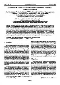
the microstructures in subsequent ZnO epilayers. Depending on the surface pre-treatment methods, the sapphire (0 0 0 1) surface exhibits three different termination layers, namely an Al monolayer, an Al bilayer and an O monolayer [3]. The atomic arrangements of the ideal sapphire (0 0 0 1) surfaces with different termination layers are shown schematically in figure 1. Since it is difficult to obtain an ideal sapphire surface with well-defined termination, various rotation domains, such as the well-known 30˚ rotation domains and recently reported 21.8˚ rotation domains [7], may coexist in the ZnO epilayers. Previous study shows that by using Ga pre-deposition to modify the sapphire (0 0 0 1) surface, rotation domains could be completely eliminated [8]. In this case, the Ga coverage should be strictly controlled to form a Ga bilayer. Searching for an alternative method to suppress the rotation domains in ZnO films, in this work, surface nitridation was adopted to modify the sapphire (0 0 0 1) surface structure and improve the film quality. Although nitridation has been widely employed in the growth of GaN epilayers on
Printed in the UK
3058
Elimination of rotation domains in ZnO epitaxial films
(b) Side view: single Al termination
(a) Top view
(c) O-termination Top layer Al
Second layer O
Fourth layer Al
Fifth layer Al
(d) Al bilayer termination Third layer Al
2.5 sccm. In the case of sample C, after O∗ irradiation, the substrate was nitridated to modify its surface structure. The nitridation was performed at a substrate temperature of 180˚C for 90 min. During nitridation, the rf power was 480 W, and the nitrogen gas flow rate was 3.0 sccm. The surface morphology and structure during the substrate treatment and ZnO growth were in situ monitored by RHEED. The crystal quality and in-plane orientation of the ZnO epilayers were characterized by a high-resolution x-ray diffractometer (HRXRD, Philips, X’pert MRD). Meanwhile, A Philips CM200 field emission gun TEM equipped with a Gatan image filtering (GIF) system was used to carry out the cross-sectional transmission electron microscopy (XTEM) experiments.
Al sublattice O sublattice
Figure 1. Atomic arrangements of the sapphire (0 0 0 1) surface: (a) top view of sapphire (0 0 0 1) with five layers of Al and O sublattices; (b) side view of five layers of sapphire (0 0 0 1) with single Al termination; (c) O termination surface; (d) Al bilayer termination.
sapphire [9, 10], this has rarely been attempted for ZnO [11]. Furthermore, so far a clear picture of the connection between sapphire surface nitridation and rotation domain elimination is still lacking. By proper nitridation of the sapphire surface to control the interface structure, we are able to grow singledomain high-quality ZnO epilayers, as observed by in situ reflection high-energy electron diffraction (RHEED) and confirmed by ex situ x-ray diffraction (XRD) measurements. For comparison, other pre-treatment processes, including thermal cleaning (TC), radio-frequency (rf )-plasma excited radical oxygen (O∗ ) irradiations and nitridation, were used to form different surface structures and to investigate the origins of rotation domains in ZnO. A cross-sectional high-resolution transmission electron microscopy (TEM) study was carried out and important information on the structure of the thin intervening AlN layer, which is necessary to suppress rotation domain formation, was obtained.
2. Experiment A rf plasma assisted molecular beam epitaxy (MBE) system (OmniVac) was used to grow ZnO films on the (0 0 0 1) sapphire substrates. The Zn flux was supplied by evaporating elemental Zn (6N) from a commercial Knudsen cell. Two rf-plasma systems (SVTA) were used to produce the active oxygen and nitrogen radicals. The gas flow rate was controlled by a mass flow controller (ROD-4, Aera). After degreasing in trichloroethylene and methanol, the sapphire substrates were chemically etched in a hot solution of H2 SO4 : H3 PO4 = 3 : 1 at 110˚C for 30 min to remove surface contamination and the damage to surface layers caused by mechanical polishing. Three samples with different sapphire pre-treatment processes were studied. Sample A was grown directly on sapphire without any intentional pre-treatment. For sample B, the substrate was thermally cleaned at 800˚C for 30 min followed by 30 min O∗ irradiation to obtain an O-terminated surface. The O∗ irradiation was carried out at an rf power of 450 W and an oxygen gas flow rate of
3. Results and discussion The in situ RHEED observations illustrate that there are 30˚ rotation domains in samples A and B. Figures 2(a)–(c) show the RHEED patterns during the growth of sample A, taken ¯ sapphire azimuth. Once the ZnO buffer layer along the [1120] deposition begins, the streaky RHEED pattern of sapphire disappears, and a spotty pattern appears. Two sets of RHEED patterns overlap together as shown in figures 2(b) and (c), which suggests that two kinds of domains coexist in the ZnO film. The complex atomic arrangement of α-Al2 O3 in figure 1(a) shows that there is a 30˚ rotation along the [0001] sapphire axis between the oxygen sublattice and α-Al2 O3 lattice (Al sublattice). After the acid etching, an atomically flat and monolayer-stepped surface could be obtained [12], indicating the coexistence of the O-terminated and Al-terminated terraces. The latter will become dominant without any intentional pre-treatment, because a single Al-terminated layer is most stable for the c-plane of α-Al2 O3 , which has been proved by low energy electron diffraction and x-ray scattering studies [4, 13]. When ZnO deposition begins on such a surface, two kinds of domains will be formed. The oxygen atoms of the first ZnO layer will form bonds with the aluminium atoms of sapphire, resulting in the formation of the main domains that follow the α-Al2 O3 lattice (labelled with arrows in figure 2(b)). Meanwhile, the zinc atoms of the first ZnO layer will form bonds with the oxygen atoms, resulting in the formation of the minor domains that follow the O sublattice of the sapphire substrate (labelled with triangles in figure 2(b)). These two kinds of domains correspond to the Zn-polar and O-polar ZnO films, respectively. Between these two kinds of domains, there is a 30˚ rotation along the [0001]sapphire axis. The existence of the domain boundaries greatly depresses the crystal quality and is especially not favourable for the twodimensional growth of the ZnO epilayer, as observed by the spotty RHEED pattern in figures 2(b)–(c). The rotation domains are completely eliminated in sample C. The sharp streaky pattern of the sapphire substrate (figure 2(d)) becomes a little weak after nitridation starts. Meanwhile, the AlN RHEED pattern can be detected together with the pattern from sapphire when the nitridation time is less than 30 min. It becomes dominant if the nitridation time is more than 50 min. Figure 2(e) shows the RHEED pattern after nitridation for 90 min. The orientation of AlN has a 30˚ in-plane rotation with respect to sapphire (0 0 0 1). A highresolution TEM study shows that the structure of the thin AlN 3059
M Ying et al
Sample A
(a) Al2O3
(b) ZnO buffer
Sample C
(a)
Zinc blende AlN
(d) Al2O3
(e) AlN
2.81 nm
(b)
2.81 nm ZnO epilayer
(c) ZnO epilayer
(f) ZnO epilayer
Zinc blende AlN
Figure 2. In situ RHEED pattern evolutions during the growth of sample A (without any substrate pre-treatment (a)–(c)), and sample C (with sapphire nitridation (d)–( f )). The e-beam incidence ¯ direction is along Al2 O3 [1120]. (a) Al2 O3 (0 0 0 1) surface before ZnO buffer layer growth; (b) as-grown ZnO buffer layer; (c) ZnO epilayer; (d) Al2 O3 (0 0 0 1) surface before nitridation; (e) after 90 min nitridation; ( f ) ZnO epilayer on the nitridated ZnO surface. The 30˚ rotation domains in ZnO film are observed in sample A, while no rotation domains are detected in the ZnO film with sapphire nitridation.
Figure 3. Cross-sectional HRTEM image (a) and its Fourier-filtered image (b) near the interfaces of ZnO/AlN/sapphire of sample C ¯ sapphire . along [1010]
layer is zincblende. Detailed information about the structure of the thin intervening AlN layer will be given later. From the RHEED evolution, it is clear that the orientation relationship between AlN and sapphire should be [111]AlN//[0001]Al2 O3 ¯ ¯ and [112]AlN//[11 20]Al 2 O3 . When the ZnO buffer layer is grown on this surface, a spotty pattern of ZnO immediately appears overlapping the AlN pattern, indicating that the ZnO film has the same orientation as that of the AlN layer, i.e. ¯ ¯ [0001]ZnO//[111]AlN and [1010]ZnO//[11 2]AlN. After a 3 h growth, the surface of sample C becomes very flat, as indicated by the streaky RHEED patterns and the intense specular spot in figure 2( f ). Another feature that can be clearly seen is the 3 × 3 reconstruction pattern, an intrinsic character of the O-polar ZnO films [14, 15], suggesting that the 30˚ rotation domains are completely eliminated and a single-domain ZnO epilayer with O-polarity was formed. The structure of the thin AlN layer is still controversial. Depending on the sapphire nitridation conditions, both wurtzite and zincblende AlN intermediate layers have been obtained [16–18]. From cross-sectional high-resolution TEM study, we find that a thin zincblende AlN layer (7–8 atom planes) with stacking faults parallel to the AlN/Al2 O3 interface has been obtained by sapphire nitridation in our experiments, as shown in figures 3(a) and (b). The epitaxial relationships are also verified to be [111]AlN//[0001]Al2 O3 ¯ ¯ and [112]AlN//[11 20]Al 2 O3 by TEM study.
The origins of rotation domains and the effect of nitridation on the elimination of these domains have also been proved by XRD φ-scans. Figure 4(a) shows the XRD ¯ for sample A. Six narrow peaks and φ-scan of ZnO (1012) six broad peaks are observed, indicating that two kinds of domains coexist in the ZnO epilayer. In comparison with ¯ (figure 4(d)), the six the six φ-scan peaks of Al2 O3 (1123) ¯ φ-scan, which correspond intense broad peaks in ZnO (1012) to the domains labelled with arrows in figure 2(b), indicate an epitaxial relationship of [0001]ZnO//[0001]Al2 O3 and ¯ ¯ [1120]ZnO//[11 20]Al 2 O3 . The other domains labeled with triangles in figure 2(b) give rise to the six weak peaks, which have an epitaxial relationship of [0001]ZnO//[0001]Al2 O3 and ¯ ¯ [1010]ZnO//[11 20]Al 2 O3 . From the peak intensities it is easy to understand that more ZnO domains formed on the α-Al2 O3 lattice than on the O sublattice because a single Al-terminated layer is most stable, as we mentioned above, which leads to more area of the sapphire (0 0 0 1) surface being covered by the Al-terminated terraces in sample A. Figure 4(b) shows the φ-scan peaks of sample B. The 30˚ rotation domain structure can also be seen clearly. Compared to sample A, the intensity of the broad peaks becomes weaker than that of the narrow peaks that originate from the domains following the O sublattice of sapphire. Although the sapphire substrate is expected to be O-terminated after O∗ irradiation,
3060
Sapphire substrate
Elimination of rotation domains in ZnO epitaxial films
XRD Intensity (arb. units)
(a)
(b)
(c)
(a)
(b)
(d)
0
60
120
180
240
300
360
φ ¯ of sample A Figure 4. The XRD φ-scans of (a) ZnO (1012) ¯ of sample B (without any substrate pre-treatment); (b) ZnO (1012) ¯ of sample C (with sapphire (with O∗ irradiation); (c) ZnO (1012) ¯ nitridation) and (d) α-Al2 O3 (1123). Note that the intensities of the broad peaks in ZnO films are reversed in samples A and B.
(c) Al2O3 lattice
it is still possible that the Al-terminated surface is formed in some regions due to oxygen desorption. As a result, broad peaks with low intensity are observed in addition to the main peaks, as shown in figure 4(b). However, for sample C, only six sharp peaks are observed (figure 4(c)), suggesting that the rotation domains are completely removed. The epitaxial orientation relationship between the ZnO epilayer and substrate is consistent with the RHEED observations, that is, [0001]ZnO//[0001]Al2 O3 and ¯ ¯ [1010]ZnO//[11 20]Al 2 O3 . The complete elimination of rotation domains in sample C is attributed to the formation of a single-domain AlN layer by nitridation. In contrast to the ZnO films grown directly on sapphire, no rotation domains were observed in this thin AlN layer formed by nitridation on various preconditioned sapphire surfaces. This demonstrates that the in-plane orientation relationship between AlN and sapphire is kept the same no matter what kind of termination layer was formed before nitridation, though the termination layer does influence the polarity of the AlN film. Theoretically, two kinds of in-plane orientation relationships between AlN and sapphire ¯ ¯ could be formed: one is [112]AlN//[11 20]Al 2 O3 and the other ¯ ¯ is [011]AlN//[11 20]Al 2 O3 , which lead to lattice mismatches of 12.6% and 35%, respectively. The probability of forming the latter orientation relationship, however, is very small due to the much larger lattice mismatch, which was confirmed by our experiments under various sapphire pre-treatments, such as O∗ irradiation, TC or atomic hydrogen pre-treatment, to form different termination layers. This thin AlN layer not only efficiently eliminates the rotation domains in the ZnO epilayer, but also acts as a template to compensate the large lattice mismatch between ZnO and sapphire and partially release the strain caused by the lattice mismatch. To understand the in-plane orientation relationship between the ZnO film and the substrate, the schematic atomic
(d)
O sublattice
Al O in Al2O3
AlN lattice ZnO lattice
Zn or O in ZnO
N or Al in AlN lattice
Figure 5. Schematics of the atomic arrangements for (a) Al2 O3 lattice and the O sublattice for c-plane sapphire, (b) ZnO lattice on the Al sublattice (Al2 O3 lattice), (c) ZnO lattice on the O sublattice and (d) ZnO on nitridated Al2 O3 (0 0 0 1).
arrangements for the [0001]ZnO//[0001]Al2 O3 epitaxial system are given in figure 5. Figure 5(a) shows the Al2 O3 lattice and the O sublattice for c-plane sapphire. When the ZnO lattice forms on top of the Al sublattice, the orientation relationship between the ZnO epilayer and the sapphire ¯ ¯ substrate would be [1120]ZnO//[11 20]Al 2 O3 , with a lattice mismatch of 32%, as shown in figure 5(b). When the ZnO lattice is formed on top of the O sublattice, the orientation ¯ ¯ would be [1010]ZnO//[11 20]Al 2 O3 , with a lattice mismatch of 18% (figure 5(c)). For samples A and B, the coexistence of the Al- and O-terminated regions results in the formation of two kinds of domains with the schematic atomic arrangements corresponding to figures 5(b) and (c), respectively. For sample C, however, the AlN layer by substrate nitridation will form only on top of the O sublattice, and the subsequent ZnO epilayer will grow according to the AlN lattice. The epitaxial relationship between ZnO, AlN and sapphire will ¯ ¯ ¯ be [1010]ZnO//[11 2]AlN //[1120]Al 2 O3 (see figure 5(d)). We find that proper sapphire nitridation is crucial for the growth of a high-quality ZnO epilayer. Figure 6 shows the XRD rocking curves of ZnO (0 0 0 2) for samples A (solid balls), B (triangles) and C (solid line), respectively. The FWHMs for the three samples are 0.51˚, 0.20˚ and 0.05˚ (180 arcsec), respectively. This further confirms that nitridation could greatly improve the crystal quality, compared to other methods. 3061
M Ying et al
Acknowledgments
XRD Intensity (arb. units)
1.0
Sample A Sample B Sample C
0.51° 0.20° 0.05°
FWHM:
0.8
This work is financially supported by the National Science Foundation of China under Grant No 60376004, 60021403, 10174089 and Ministry of Science and Technology of China under Grant No 2002CB613502.
0.6
References
2
0.4
0.2
0.0
-1.0 -0.8 -0.6 -0.4 -0.2 0.0
0.2
0.4
0.6
0.8
1.0
ω (degree) Figure 6. The XRD ω-scans of sample A (without any substrate pre-treatment), B (with O∗ irradiation) and C (with sapphire nitridation).
4. Summary Different rotation domain structures were observed in ZnO films prepared under various sapphire substrate pre-treatment processes. The crystal quality and in-plane orientation of the ZnO epilayers were investigated by using in situ RHEED observations and ex situ XRD measurements. It is found that by an appropriate nitridation treatment of the substrates, the rotation domains in the ZnO film can be completely suppressed. This is attributed to the formation of a thin single-domain AlN layer.
3062
[1] Chen Y, Bagnail D and Yao T 2000 Mater. Sci. Eng. B 75 190 [2] Fons P, Iwata K, Yamada A, Matsubara K and Niki S 2000 Appl. Phys. Lett. 77 1801 [3] Walters C F, McCarty K F, Soares E A and Van Hove M A 2000 Surf. Sci. 464 L732 [4] Toofan J and Watson P R 1998 Surf. Sci. 401 162 [5] Godin T J and LaFemina J P 1994 Phys. Rev. B 49 7691 [6] Suzuki T, Hishita S, Oyoshi K and Souda R 1999 Surf. Sci. 437 289 [7] Du X L, Murakami M, Iwaki H and Yoshikawa A 2002 Phys. Status Solidi a 192 183 [8] Du X L, Murakami M, Iwaki H, Ishitani Y and Yoshikawa A 2002 Japan. J. Appl. Phys. 41 L1043 [9] Moustakas T D, Molnar R J, Lei T, Menon G and Eddy C R 1992 Mater. Res. Soc. Symp. Proc. 242 427 [10] Felice R D and Northrup J E 1998 Appl. Phys. Lett. 73 936 [11] Wang X Q, Iwaki H, Murakami M, Du X L, Ishitani Y and Yoshiwawa A 2003 Japan. J. Appl. Phys. 42 L99 [12] Kimura R and Takahashi K 2000 Japan. J. Appl. Phys. 39 1039 [13] Guenard P et al 1998 Surf. Rev. Lett. 5 321 [14] Chen Y F, Ko H J, Hong S K and Yao T 2000 Appl. Phys. Lett. 76 559 [15] Chen Y F, Ko H J, Hong S K, Yao T and Segawa Y 2000 J. Cryst. Growth 214/215 87 [16] Moustakas T D et al Mater. Res. Soc. Symp. Proc. 242 427 [17] Uchida K, Watanabe A, Yano F, Kouguchi M, Tanaka T and Minagawa S 1996 J. Appl. Phys. 79 3487 [18] Heinlein C, Grepstad J, Berge T and Riechert H 1997 Appl. Phys. Lett. 71 341