B. Yao is with the School of Mechanical Engineering, Purdue University,. West Lafayette, IN ... account by any high-performance robust motion controller. Previously ...... automotive control, and control of manufacturing processes. Mohammed ...
IEEE/ASME TRANSACTIONS ON MECHATRONICS, VOL. 2, NO. 2, JUNE 1997
63
High-Performance Robust Motion Control of Machine Tools: An Adaptive Robust Control Approach and Comparative Experiments Bin Yao, Mohammed Al-Majed, and Masayoshi Tomizuka, Fellow, IEEE
Abstract—This paper studies the high-performance robust motion control of machine tools. The newly proposed adaptive robust control (ARC) is applied to make the resulting closed-loop system robust to model uncertainties, instead of the disturbance observer (DOB) design previously tested by many researchers. Compared to DOB, the proposed ARC has a better tracking performance and transient in the presence of discontinuous disturbances, such as Coulomb friction, and it is of a lower order. As a result, time-consuming and costly rigorous friction identification and compensation is alleviated, and overall tracking performance is improved. The ARC design can also handle large parameter variations and is flexible in introducing extra nonlinear robust control terms and parameter adaptations to further improve the transient response and tracking performance. An anti-integration windup mechanism is inherently built in the ARC and, thus, the problem of control saturation is alleviated. Extensive comparative experimental tests are performed, and the results show the improved performance of the proposed ARC. Index Terms—Adaptive control, machine tools, motion control, robust control, servo control.
I. INTRODUCTION
M
ODERN mechanical systems, such as machine tools, microelectronics manufacturing equipment, robot manipulators, and automatic inspection machines, are often required to operate in high speed to yield high productivity. At the same time, precision/accuracy requirement becomes more and more stringent because of factors like the reduced size of components in modern mechanical devices or microelectronics products and high-quality surface-finishing requirements. As a result, high-performance robust motion control is becoming increasingly important for processes such as machining. The goal is to achieve nominal tracking errors near the measurement resolution, including during transients. The resulting closedloop system should have not only stability robustness, but also performance robustness, which is an important requirement when dynamic characteristics vary from one unit to another and/or when the characteristics of a unit vary during operation. In motion control, the major sources of uncertainties are friction, inertia, and external disturbances, such as cutting forces Manuscript received January 14, 1997; revised March 24, 1997. Recommended by Guest Editor K.-M. Lee. This work was supported in part by the National Science Foundation under Grant DMI 9301012. B. Yao is with the School of Mechanical Engineering, Purdue University, West Lafayette, IN 47907 USA. M. Al-Majed and M. Tomizuka are with the Mechanical Engineering Department, University of California, Berkeley, CA 94720 USA. Publisher Item Identifier S 1083-4435(97)04811-4.
during machining. These uncertainties should be taken into account by any high-performance robust motion controller. Previously, Tomizuka and his coworkers [1] proposed the combination of friction compensation, a disturbance observer, a position feedback controller, and a feedforward controller as a general controller structure for high-performance robust motion control. Among these four elements, disturbance observer, introduced by Ohnishi [2], [3] and refined by Umeno and Hori [4], is used to estimate disturbances to make the system robust to plant model uncertainties. The disturbance observer is not limited to dc disturbances, and the bandwidth for disturbance rejection can be adjusted. However, it is designed based on the linear control theory and it cannot handle discontinuous disturbances, such as Coulomb friction, well. As a result, friction compensation [5] is added to improve the robustness of the overall system in addition to disturbance observer. If major uncertainties are removed by the disturbance observer and friction compensation, then it is very easy to design an asymptotically stable position feedback loop by linear feedback control theory. To recover the dynamic delay, the desired output needs to be processed by a feedforward controller, which can be accomplished by the zero-phase error tracking controller (ZPETC) proposed by Tomizuka [6], [1]. Recently, Yao and Tomizuka proposed a new approach, adaptive robust control (ARC) [7]–[9], for high-performance robust control of uncertain nonlinear systems in the presence of both parametric uncertainties and uncertain nonlinearities. The approach effectively combines the design techniques of adaptive control (AC) and those of deterministic robust control (DRC) [e.g., sliding mode control (SMC)] and improves performance by preserving the advantages of both AC and DRC. Specifically, through proper controller structure as in DRC [10], [11], the proposed ARC achieves a guaranteed performance in terms of both the transient error and the final tracking accuracy in general. This result overcomes the drawbacks of poor transient performance and poor robustness to uncertain nonlinearities of AC [12], [13], and makes the approach attractive from the viewpoint of applications. Through parameter adaptation, as in adaptive control, to reduce model uncertainties, the proposed ARC achieves asymptotic tracking in the presence of parametric uncertainties without resorting to a discontinuous control law [10] or an infinite gain in the feedback loop [14]. In this sense, ARC has a better tracking performance than DRC. The design is conceptually simple and amenable to implementation. Comparative experimental
1083–4435/97$10.00 1997 IEEE
64
IEEE/ASME TRANSACTIONS ON MECHATRONICS, VOL. 2, NO. 2, JUNE 1997
Fig. 2. Disturbance observer.
disturbance observer is not causal in the DOB loop), in implementation, one must use the low-pass causal filter As a result, the resulting closed-loop system from to becomes
Fig. 1. Controller structure with disturbance observer.
results for trajectory tracking control of robot manipulators [9] have shown the advantages of the proposed ARC and the improvement of performance. A general framework of the proposed ARC is formulated in terms of ARC Lyapunov functions [8], [9]. Through the backstepping design, ARC Lyapunov functions have been successfully constructed for a large class of multi-input multi-output (MIMO) nonlinear systems transformable to a semistrict feedback form [8], [9]. In this paper, ARC will be applied to make the resulting closed-loop system robust to plant model uncertainties, instead of the disturbance observer tested in [1] for the highperformance motion control of a machine tool. Comparative experimental results done on the Matsuura MC510VSS highspeed vertical machining center will be shown to illustrate the advantages of ARC. II. CONTROLLER STRUCTURE FOR ROBUST DIGITAL MOTION CONTROL In [1], Tomizuka and Lee demonstrated the robustness and accuracy of a motion controller that is composed of four modules, as depicted in Fig. 1. These four modules are: 1) disturbance observer as a velocity loop feedback controller (DOB); 2) position loop feedback controller; 3) feedforward tracking controller for the desired output; and 4) friction compensator. In the figure, is the plant model for the velocity loop, i.e., where is the control input and represents disturbances, including friction force and external disturbances such as cutting forces. is the nominal plant model or the identified model and represents the friction compensation. The essence of DOB in the velocity loop is to estimate the lumped “disturbances” (1) which represents the uncompensated friction force, external disturbances, and parametric uncertainties. The estimated disturbance signal is fed back to cancel the lumped disturbance so that the resulting closed-loop system from the new to the output behaves like the nominal synthesis input model, without the effect of model uncertainties. This point can be seen by the fact that, if we can construct an ideal disturbance observer, i.e., if then we have the relationship in the absence of measurement noise. However, because of the causality problem of the ideal
(2) As can be seen from these equations, the DOB design becomes a matter of proper selection of the -filter to determine robustness and disturbance suppression performance. In the low-frequency range, if the three transfer functions in (2) reduce to (3) which implies that the DOB makes the actual plant behave like the nominal plant. This will ensure performance robustness of the overall motion controller by canceling the lumped disturbance. However, (3) also shows that the measurement noise is passed unaffected. To filter out the noise at high frequency, the -filter must be designed so that in the high frequency range. For implementation, the above DOB is redrawn in Fig. 2, and its discrete time equivalent is obtained using bilinear transformation. Since major disturbances, especially low-frequency disturbances, are eliminated by DOB, the dynamics of the inner loop from to can now be treated as described by the nominal plant model Thus, a stabilizing position controller can be easily designed for the transfer function
the transfer function from to in discrete-time domain with a zeroth-order hold. The reason that this control design is done in discrete-time domain is that the final controller has to be implemented digitally, and digital effect has to be considered whenever possible to achieve high accuracy. In this way, the closed-loop system from the reference input to the output can be described by
where
YAO et al.: HIGH-PERFORMANCE ROBUST MOTION CONTROL OF MACHINE TOOLS
For our experiments on the machine tool control later, a simple proportional-plus-derivative (PD) controller is sufficient for For time-varying trajectories, a feedforward controller has to be employed to recover the dynamic delay of the closed-loop system in the selected frequency range, which can be done by the ZPETC proposed by Tomizuka [6]. Theoretically, there is not much need to add friction compensation, since DOB is supposed to estimate all disturbances on-line. However, since DOB is designed based on linear system theory and it is only effective in the low frequency range, it cannot handle discontinuous disturbances well where we have a broad spectrum of frequency contents. In machine tool control, one major source of discontinuous disturbances is the friction. As a result, friction compensation is also introduced to alleviate the effect of discontinuous disturbances. Remark 1: To gain further insights about the DOB, we now analyze the closed-loop stability by neglecting the effect of discretization, i.e., we will use instead of in the following. From (2) and Fig. 1, the transfer function from to is
(4)
65
zero velocity). As a result, one has to use sophisticated friction model to compensate for the effect of discontinuous disturbances, as was done in [1]. Such a procedure is timeconsuming and sometimes may not be so practical. For applications such as cutting, cutting force appears in the middle of motion and may not be identified in advance. Thus, it is of practical significance if we can consider the effect of discontinuous disturbances in the design stage. In this section, instead of DOB, the idea of adaptive robust control (ARC) approach proposed by Yao and Tomizuka in [7] and [8] will be applied to design a simple yet sufficient ARC controller for the machine tool control to reduce the effect of discontinuous disturbances. The resulting controller will be used in the experiments later and compared to DOB. To simplify the design process, we consider the following actual machine tool dynamics used in [1] (for each axis) or (7) where is the inertia and is the damping coefficient, which includes the viscous friction force. As in DOB design, the objective is to synthesize a control input such that the resulting system from to behaves like its nominal model, i.e., we want or (8)
where
is the model mismatch. Notice that is the nominal closed-loop characteristic which is stable. From (4), the system equation when has robust stability if the model uncertainty satisfies (5)
Since we want for a broad range of to have a good estimate of the disturbance, from (5), the model mismatch should satisfy (6)
and are the nominal values of and , where respectively. For simplicity, in this section, we assume that the variations of and are not so big that their effects can be neglected in the design, i.e., and in the following. This assumption is true for a lot of applications, as in the experiments reported later. The general case can be dealt with in the same way. Thus, the focus of this section is on how to deal with the bounded discontinuous disturbance from which one can easily gain insights about the proposed ARC and its advantages. Define a switching-function-like quantity as (9)
to guarantee closed-loop stability. Equation (6) clearly shows that the model mismatch should not be too large in the DOB design. As a result, DOB cannot handle large parameter variations. III. A SIMPLE ADAPTIVE ROBUST CONTROLLER FOR MACHINE TOOLS In Section II, one of the main features in the design of highperformance digital motion control is to use DOB to make the closed-loop system robust to plant model uncertainties. As mentioned there, it cannot handle discontinuous disturbances well. In fact, previous experimental results showed that the largest tracking errors are caused by the discontinuous disturbances (e.g., discontinuous Coulomb friction around
where
From (7) and (9), (10)
If (or sliding mode called in the field of sliding mode control), then, we have the desired relationship in (8). However, because of the causality problem (the relationship between and is static), the best one can do by using feedback is to make as small as possible. If all signals involved are uniformly continuous, then means In a sense, small means small So in the following, we are going to synthesize such that is as small as possible while minimizing the effect of discontinuous disturbances, which will be done by ARC.
66
IEEE/ASME TRANSACTIONS ON MECHATRONICS, VOL. 2, NO. 2, JUNE 1997
Let the control law be (11) is any fixed friction compensation, and where is the estimate of the lumped uncompensated disturbance Since is bounded, one can assume that (12) where and are known. Substituting (11) into (10), the error dynamics is (13) where is the estimation error. Equation (13) can be considered as a stable first-order system with respect to (w.r.t.) with a bounded uncompensated disturbance input if a fixed is used as in usual robust control. Thus, and can be made as small as possible by increasing feedback gain This is what a robust control approach usually does—use certain controller structures and feedback gains to attenuate the effect of modeling uncertainties (here, high gain is used to attenuate the effect of However, in practice, feedback gains have up-limits because of the finite bandwidth of every physical system. Thus, the achievable accuracy of a robust control in implementation is limited in a sense. As seen from (13), once is fixed, the actual tracking error will be proportional to the size of the modeling uncertainty So, in order to further improve performance, one must try to reduce the modeling uncertainty, which can be done by using certain adaptation mechanisms, as shown below. Here, we update on-line by the following adaptation law: if
and and
(14)
otherwise where is the adaptation rate. It can be shown, as in [7], that the above type of adaptation law guarantees that and
(15)
Theorem 1: If the ARC law (11) is applied, then: 1) in general, the tracking error can be made as small as possible by increasing feedback gain ; 2) in the presence of constant disturbances, i.e., being an unknown constant as normally assumed in the field of adaptive control, the modeling uncertainty converges to zero and zero final tracking error can be obtained for any feedback gain Proof: The theorem can be proved in the same way as in [7]. Remark 2: To gain further insights about ARC, let us is within the range assume that the estimated that is supposed to lie. Then, substituting (14) into (13), we have
low-frequency component of Equation (16) also provides us some insights about the tuning of adaptation rate which is important for achieving good tracking performance, but often missed in the adaptive control community because of the complex structures of the resulting controller structures. As can be seen from the equation, should be chosen according to the value of used in robust control. If a high-gain feedback is used, then, a large adaptation rate can be chosen to increase the bandwidth of the resulting controller to achieve a better transient performance and a better tracking performance, as long as the bandwidth of the controller does not exceed the physical limit due to neglected factors such as high-frequency dynamics. This philosophy has been employed by authors in several applications, such as the motion control of robot manipulators [7], [9], and an improved tracking performance has been obtained. This ARC philosophy differs fundamentally from the usual concept held in the adaptive control community in the sense that researchers in the adaptive control community tend to neglect the role of robust control feedback. As a result, a conservative adaptation rate has to be used, and poor transient tracking performance is reported in practice. The above analysis is valid if the parameter adaptation is supposed to do its job, namely, is within the range that is supposed to lie. In general, this assumption is not guaranteed, especially when multiple parameters are adapted and the desired trajectory is not persistently exciting, and the system has uncertain nonlinearities (e.g. time-varying Those factors lead to the unknown transient problem and nonrobustness problem of general adaptive control. Extra efforts have to be made in order to use parameter adaptation in the robust control design without having the instability problem of adaptive control. Here, for this simple case, it is done by the popularly used projection method in (14). See [8] and [9] for general cases. Remark 3: The proposed ARC has the following nice feature: a built-in mechanism to avoid the problem of integration windup when the system is subjected to some unexpected large disturbances for a short period. This feature is of practical significance, since the actual control input always has a saturation limit and there has been a lot of work done to prevent it [15]. As seen from (14) and (15), no matter if the control is saturated or not and how big the actual disturbance is, is always within the preset region So, during the period when the large disturbance appears, the system is essentially described by (13), a first-order system w.r.t. with a bounded disturbance which has a much better robustness than high-order systems. Once the large disturbance disappears and returns to the preset region the ideal performance in Theorem 1 is recovered. Remark 4: In the above development, for simplicity, only a simple proportional feedback is used for the robust control term In order to further improve transient performance, extra nonlinear robust feedback control terms can be added as follows:
(16)
(17)
Thus, in this case, the adaptation law functions as adding an integrator of which is the reason that it can identify the
where is any function such that and can be discontinuous. can be chosen to be near zero when
YAO et al.: HIGH-PERFORMANCE ROBUST MOTION CONTROL OF MACHINE TOOLS
67
is small and large when is large. By doing so, when is large, where the effect of measurement noise is not important, the added robust control strength will force to converge more quickly. When is small, where the effect of measurement noise becomes noticeable, the robust control strength is reduced to alleviate the effect of measurement noise. Remark 5: In the above development, although the effect of parameter variations was not considered, the resulting closedloop system can tolerate larger parameter variations than the DOB design. To see this, substitute (11) into (7): Fig. 3. A simple adaptive robust controller.
(18) where
From (9),
satisfies the following two conditions:
i) ii) (19) Substitute (19) into (18), and the closed-loop system is
(24) in which and are two positive design parameters. The adaptation law for is the same as in (14), and the adaptation laws for and are
(20) Thus, the closed-loop system is stable if all roots of the denominator of (20) have negative real part. For simplicity, assume that in the following, which is used in the experiments. By using Routh–Hurwitz criterion, the system is stable if
(25) where and projections as in (14), i.e.,
are positive adaptation rates and the and are defined in the same way
if
(26)
otherwise (21) which is a much less restrictive condition than (6).
stands for or Similar to (15), the above in which adaptation laws guarantee that [7] and
IV. GENERAL ADAPTIVE ROBUST CONTROL OF MACHINE TOOLS
and
In Section III, a simple ARC controller is proposed to deal with bounded disturbances. In this section, parameter variations due to the inertia and the damping coefficient will also be considered and a general ARC controller will be presented. It is assumed that and where and are arbitrary, but known, positive numbers. As in Section III, we want to achieve (8), which can be indirectly accomplished by making defined in (9) small. From (7), (22) Let the control law be (23)
(27)
Theorem 2: If the ARC law (23) with the adaptation laws (14) and (25) is applied, then: 1) in general, the control input is bounded and the tracking error can be made as small as possible by increasing and/or decreasing ; 2) in the presence of constant disturbances, i.e., being an unknown constant, in addition to the results in 1), zero final tracking error can be obtained. Remark 6: As seen from (24), the robust control term is synthesized to dominate the model uncertainties coming from both the parametric uncertainties and and the disturbance to attenuate their effect, which is possible by using a bounded control, due to the employment of the robust adaptation laws in (25). There is some flexibility in choosing to satisfy (24). This flexibility can be used to satisfy particular needs of an application. For example, if less
68
IEEE/ASME TRANSACTIONS ON MECHATRONICS, VOL. 2, NO. 2, JUNE 1997
Fig. 4. Experimental setup.
computation time is desirable, a simple chosen as long as satisfies
can be
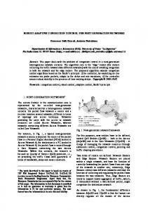
(28) It can be shown in the same way as in [8] that the above choice of satisfies (24). Proof: Theorem 2 can be proved in the same way as in [8] and [7]. V. COMPARATIVE EXPERIMENTS A. Experimental Setup The – table of a Matsuura 510VSS high-speed vertical machining center is used to conduct the comparative study. axis and axis move horizontally with axis on the top of axis to produce a planar motion. axis moves vertically. Fig. 4 depicts the necessary hardware setup that we built to replace the machine tool Yasnac MX-3 controller. The experimental controller is made of a personal computer (PC) and a digital signal processing (DSP) board. The DSP board is a Spectrum TMS320C30, and it runs the servo control code. In order for the DSP to perform the servo control, it is equipped with quadrature decoders to measure the position of each axis and D/A outputs to send command to them. The resolution of the encoder is 12 000 counts per revolution for the motor or 1 m per pulse in terms of the translation motion of the axes. Velocity signal used in the experiments is then obtained by the difference of two consecutive position measurements with a first-order filter (corner frequency is 3750 rad/s). The PC is based on Intel 486-66DX2 and is used to control the DSP through its AT bus and it only serves as a simple user interface. In the experiments, only and axes are used.
Fig. 5. The profile of the desired trajectory.
Standard least-square identification is performed to obtain and The identified values are
for
for rate
V/(m/s
and
V/(m/s
and
V/(m/s)
axis and V/(m/s)
axis. All experiments are conducted with a sampling ms.
B. Performance Indexes Since we are interested in tracking performance, commonly used performance measures, such as the rising time, damping, and steady-state error, are not adequate. So far, we do not have a clear set of performance indexes defined to measure the quality of each control algorithm. Previously reported experiments, such as in [1], plotted each tracking error and used
YAO et al.: HIGH-PERFORMANCE ROBUST MOTION CONTROL OF MACHINE TOOLS
69
Fig. 6. Tracking errors without friction compensation.
visual inspection to obtain the quality of control algorithms. However, such a method is not adequate for processing a large number of experimental results. Furthermore, control effort and the degree of control input chattering are not examined, which is a factor that should be considered in judging if the experimental comparison is fair or not. Here, like the comparative experimental results for robot motion control [9], the following indexes will be used: • scalar valued norm, is used as an objective numerical measure of average tracking performance for an entire error curve where represents the total running time; • the maximal absolute value of the tracking error, is used as an index of measure of transient performance; •
the average control input, is used to evaluate the amount of control effort; the normalized control variations, • is used to measure the degree of control input chattering, where
the average of control input increments.
C. Controller Gains The choice of feedback gains is crucial to achieve a good tracking performance for all controllers. A discussion of the gain tuning processes for each controller follows in detail. In general, the larger the feedback gains, the smaller the tracking errors. However, if the gains are too big, the system will be subject to severe control chattering, due to the measurement noise and the neglected high-frequency dynamics, and a large noisy sound can be heard. After the gains exceed certain limits, the structural resonance is excited because of severe control chattering, and the system goes unstable. Thus, in order to achieve a fair comparison, we will try to tune gains of each controller, such that the tracking errors of each controller are minimized, while the degree of control chattering is maintained within the allowable limit. Three controllers are compared. 1) PD: This is the controller obtained after we take off either DOB loop in Fig. 1 or ARC loop in Fig. 3. For the machine tool dynamics described by (8), a PD controller is sufficient for stabilization purposes, which is obtained by the bilinear transformation of the continuous PD controller so that the resulting nominal closed-loop transfer function is critically damped with a corner frequency ZPETC is designed by treating the zero near the unit circle as an uncancelable zero.
70
IEEE/ASME TRANSACTIONS ON MECHATRONICS, VOL. 2, NO. 2, JUNE 1997
Fig. 7. Tracking errors with friction compensation.
2) DOB: This is the controller structure tested in [1], which is described in Section II and uses the same PD position feedback loop and ZPETC as in the PD case. The same filter as in [1] and [4] is used, i.e., Within its allowable limit, the smaller the time constant is, the larger the resulting bandwidth of the controller and the better the tracking performance. So, in the experiments, is gradually reduced until it reaches its limit (further decrease will destabilize the system because of the neglected high-frequency dynamics) to obtain the best tracking performance that DOB can produce. The limiting value is 3) ARC: This is the controller described by (11) in Section III, which is very simple, yet sufficient for the existing experimental setup, as illustrated by the experimental results. As seen from Theorem 1, the larger the robust feedback gain is, the better the tracking performance. So, in the experiments, as in DOB, here, is gradually like in the tuning of increased until the effect of measurement noise and neglected is fixed, adaptation dynamics becomes noticeable. After rate is chosen such that (16) is critically damped or overly and are used in the damped. and are 2 and 2 V, experiments. The preset values respectively.
D. Comparative Experimental Results for Disturbance Rejection 1) Air-Cutting Experiments: In this section, air cutting is performed to test the tracking performance of each algorithm, since a higher speed can be commanded for each axis. We use the identified parameters of the machine tool under no-load condition as the nominal model, i.e., and First, we test all three controllers for sufficient smooth desired trajectories. A circle with 20-mm radius, shown in Fig. 5, is used. The – table accelerates on the circle until it reaches the desired feed rate of 7 m/min. After one circle, the table decelerates to a stop. The desired trajectories for and axes are planned by selecting an angular acceleration profile with continuous derivatives up to second order. We test the reliability of the experimental results by running the same controller several times. It is found that the standard deviation of the error from different runs is negligible. The following test sets are first performed. a) Set 1: All three controllers are run without friction compensation. b) Set 2: All three controllers are run with a simple Coulomb friction compensation as given by (29)
YAO et al.: HIGH-PERFORMANCE ROBUST MOTION CONTROL OF MACHINE TOOLS
71
Fig. 8. Tracking errors in the presence of large disturbances.
where is the friction magnitude. The friction magnitude axis is V and for axis is for V. The input voltage was gradually increased from zero, and was obtained as the voltage to initiate the motion. c) Set 3: A very large step disturbance (a simulated s and removed electrical signal) is added around s to test the performance robustness of each around controller. The experimental results in terms of performance indexes are given in Table I, where the unit for tracking errors is m and the unit for inputs is volts (V). As can micron and axes, in terms be seen from the table, for both and PD performs of both performance indexes poorly compared to DOB and ARC for all three sets. Both DOB and ARC have satisfying tracking performance, due to their disturbance rejection capability. Thus, in the following, we will focus on the comparison between DOB and ARC. and axes are given For Set 1, the tracking errors of in Fig. 6. As expected, the tracking errors have large spikes s and s for , and s for (around when the velocities change directions to create a discontinuous disturbance by Coulomb friction. However, ARC’s spikes are much smaller. This result illustrates that ARC has a better ability in dealing with discontinuous disturbances. Overall,
Fig. 9. The profile of the desired trajectory.
in terms of both and ARC has a better tracking performance than DOB. In Set 2, because of the rough compensation of the discontinuous Coulomb friction, the tracking errors shown in Fig. 7 do not have noticeable spikes. Again, for both axes, ARC performs better in terms of both and
72
IEEE/ASME TRANSACTIONS ON MECHATRONICS, VOL. 2, NO. 2, JUNE 1997
Fig. 10.
Tracking errors for nonsmooth desired trajectories.
TABLE I COMPARATIVE EXPERIMENTAL RESULTS FOR DISTURBANCE REJECTION
TABLE II PERFORMANCE INDEXES
The tracking errors for Set 3 are given in Fig. 8. As seen from the figures, the added very large disturbance does not affect DOB and ARC performance much, except for the spike when the sudden change of the disturbance occurs. This result shows the performance robustness of the DOB and ARC designs. Again, ARC performs better in terms of both and For all tests, as seen from the table, ARC and DOB use almost the same amount of control effort, since we are doing trajectory tracking control. ARC has a slightly larger degree of control input chattering. This difference is caused by the following two factors: noisy velocity signal and encoder resolution. ARC uses the velocity signal directly in the design, while DOB’s higher order -filter alleviates the noise effect.
ARC’s tracking errors are very small (within 2 m, almost within the encoder resolution (1 m. Thus, because of the quantization nature of the encoder measurement, the control input has to be of high-frequency small jumps. In practice, machine tools generate the desired trajectories by connecting different segments like lines, circles, and parabolas, and continuous acceleration profile is hard to obtain. To test the controllers for these applications, we rerun the controllers in Set 2 for the desired trajectory shown in Fig. 9. For this trajectory, we use the linear segments for acceleration and deceleration so that the feedrate on the circle can be maintained at the constant speed of 7 m/min for good surface finishing. This will result in a discontinuous acceleration axis at the connection points of the two line profile for
YAO et al.: HIGH-PERFORMANCE ROBUST MOTION CONTROL OF MACHINE TOOLS
Fig. 11.
73
Tracking errors for a heavy load of more than 100 kg.
segments and the circle (around s and s). The performance indexes and the tracking errors of both DOB and ARC are shown in Set 4 of Table II and Fig. 10, respectively, from which we can see that ARC has a better ability in dealing with the discontinuous acceleration profile s). All these test results (smaller tracking error around show the superior tracking performance of ARC. Finally, a heavy load of more than 100 kg is mounted on the machine tool and the above DOB and ARC schemes are rerun to test their performance robustness to parameter variations due to the added load inertia. The performance indexes and the tracking errors of both DOB and ARC are shown in Set 5 of Table II and Fig. 11, respectively, which is almost the same as the no-load situation (Fig. 7 or Set 2 of Table I). 2) Cutting Experiments: Two experiments were conducted for the high-speed machining of aluminum using a spindle speed of 14 000 r/min and a high-speed steel, two-flute, 25.4mm diameter end mill, as shown in Fig. 12. Although the experimental servo systems are capable of tracking trajectories at a much higher feedrate as in air-cutting experiments, a feedrate of 3 m/min was used, due to the limited maximum spindle speed. Using a smaller diameter end mill permits the use of higher feedrates, but more tool deflection will be introduced. A small cylinder was machined from an aluminum
Fig. 12. Cutting experimental setup.
block with 9.931-mm circular diameter for the end milling experiments. The axial depth of cut was 5 mm, while the radial depth was 0.2 mm. The desired diameter was 9.531 mm. As can be seen from Fig. 12, the aluminum specimen, which is fixed to the machine tool table, moves in a circular path around the tool. The two linear segments were used for acceleration and deceleration, respectively, as in Set 4. First, the specimen was machined using the servo controller based on the ARC. Then, the DOB-based controller was used
74
IEEE/ASME TRANSACTIONS ON MECHATRONICS, VOL. 2, NO. 2, JUNE 1997
Fig. 13.
Tracking errors for cutting experiments.
Fig. 14.
Tracking errors for
n
J
=
1J : 3 id
in another run under the same conditions. The performance indexes and the tracking errors of both controllers based on optical encoder measurement are shown in Set 6 of Table II and Fig. 13. The results show that both controllers perform
well for the cutting experiments, and ARC achieves a better tracking performance than DOB. Comparing the results with the corresponding higher speed air-cutting results shown in Fig. 10, we can see that the results correlate each other well.
YAO et al.: HIGH-PERFORMANCE ROBUST MOTION CONTROL OF MACHINE TOOLS
^ for
Fig. 15.
Estimated inertia
Fig. 16.
Tracking errors for
J
Jxn
Jn
=
=
1 2
1 3
75
Jid :
Jxid
and
Jyn
=
1 1:8
Jyid :
The slightly larger tracking errors in air cutting is due to the use of a higher feedrate and smaller circle diameter. Thus, the air-cutting results presented before are good indications for what will happen in high-speed machining. It should be
noted that the two experiments were performed to show that the cutting load does not affect the positioning accuracy in any major way and that the cutting conditions were not optimized for other considerations, such as surface finish.
76
IEEE/ASME TRANSACTIONS ON MECHATRONICS, VOL. 2, NO. 2, JUNE 1997
E. Comparative Experimental Results For Parameter Variations
is built in the ARC controller and, thus, the problem of control saturation is alleviated. Extensive comparative experimental tests were performed and the results show the improved performance achieved by the proposed ARC.
As seen from the test Set 5 above, both DOB and ARC are very robust to small parameter variations. In this section, we consider large parameter variations. Since actual load will not change the inertia of the system much (e.g., a heavy load of more than 100 kg), we deliberately choose to create large model mismatch due to the different normally does not change inertia. Damping coefficient All tests are much and, thus, we still set performed under no-load situation. adaptation law for To cope with large variation of is added to the above ARC controller. is the inertia and the supposed to vary within the range of adaptation law for is obtained by (25) where for axis and for axis. The initial value of is set to the nominal value i.e., The control is used, as input is calculated from (23) in which explained in Remark 6, with the same gain used previously. is set to one-third of the identified value, In the first test, In other words, the actual inertia is three times i.e., more than the assumed nominal inertia (assuming a perfect Not surprisingly, DOB off-line identification, i.e., goes unstable, which agrees with the prediction by Remark The tracking error of the proposed 1, since ARC is shown in Fig. 14 and performance indexes are given in Set 7 of Table II. It can be seen that ARC achieves almost the same tracking performance as the case of no parameter variation (Fig. 7 or Set 2 of Table I) and, thus, is very robust to parameter variations. It is worth noting that the estimated inertia shown in Fig. 15 does not converge to its true value, although theoretically persistent excitation condition is satisfied. and In the second test, we set In such a case, DOB is stable, but near unstable, which agrees with the prediction of Remark 1, since and However, it has very large tracking errors, as shown in Fig. 16. Performance indexes of DOB and ARC are given in Set 8 of Table II. As seen from the figure and the indexes, ARC is very robust to the inertia variation and its performance is virtually unaffected. VI. CONCLUSIONS High-performance robust motion control of machine tools was studied in this paper. Instead of DOB tested before, ARC was applied to make the closed-loop system robust to the plant model uncertainties. The resulting ARC controller is very simple and is of low order. Compared to DOB, the proposed ARC controller has a better tracking performance and transient in the presence of discontinuous disturbances, such as Coulomb friction. As a result, time-consuming and costly rigorous friction identification and compensation is alleviated and overall tracking performance is improved. The ARC design can also handle large parameter variation and is flexible in introducing extra nonlinear robust control terms and parameter adaptations to further improve the transient response and tracking performance. Anti-integration windup mechanism
REFERENCES [1] H. S. Lee and M. Tomizuka, “Robust motion contoller design for highaccuracy positioning systems,” IEEE Trans. Ind. Electron., vol. 43, pp. 48–55, Feb. 1996. [2] K. Ohnishi, “A new servo method in mechatronics,” Trans. Jpn. Soc. Elect. Eng., vol. 107, no. D, pp. 83–86, 1987. [3] K. Ohnishi, M. Shibata, and T. Murakami, “Motion control for advanced mechatronics,” IEEE/ASME Trans. Mechatron., vol. 1, pp. 56–67, Mar. 1996. [4] T. Umeno and Y. Hori, “Robust speed control of dc servomotors using modern two degrees-of-freedom controller design,” IEEE Trans. Ind. Electron., vol. 38, pp. 363–368, Oct. 1991. [5] E. Tung, G. Anwar, and M. Tomizuka, “Low velocity friction compensation and feedforward solution based on repetitive control,” Trans. ASME, J. Dyn. Syst. Meas. Control, vol. 115, no. 2(A), pp. 279–284, 1993. [6] M. Tomizuka, “Zero phase error tracking algorithm for digital control,” Trans. ASME, J.Dyn. Syst. Meas. Control, vol.109, no.1, pp.65–68, 1987. [7] B. Yao and M. Tomizuka, “Smooth robust adaptive sliding mode control of robot manipulators with guaranteed transient performance,” Trans. ASME, J. Dyn. Syst. Meas. Control, vol. 118, no. 4, pp. 764–775, 1996. [8] B. Yao and M. Tomizuka, “Adaptive robust control of a class of multivariable nonlinear systems,” in Proc. IFAC World Congr., 1996, vol. F, pp. 335–340. [9] B. Yao, “Adaptive robust control of nonlinear systems with application to control of mechanical systems,” Ph.D. dissertation, Mech. Eng. Dep, Univ. California, Berkeley, Jan. 1996. [10] V. I. Utkin, Sliding Modes in Control Optimization. Berlin, Germany: Springer-Verlag, 1992. [11] M. J. Corless and G. Leitmann, “Continuous state feedback guaranteeing uniform ultimate boundedness for uncertain dynamic systems,” IEEE Trans. Automat. Contr., vol. 26, pp. 1139–1144, Oct. 1981. [12] J. J. E. Slotine and W. Li, “Adaptive manipulator control: A case study,” IEEE Trans. Automat. Contr., vol. 33, pp. 995–1003, Nov. 1988. [13] M. Krstic, I. Kanellakopoulos, and P. V. Kokotovic, Nonlinear and Adaptive Control Design. New York: Wiley, 1995. [14] Z. Qu, D. M. Dawson, and J. F. Dorsey, “Exponentially stable trajectory following of robotic manipulators under a class of adaptive controls,” Automatica, vol. 28, no. 3, pp. 579–586, 1992. [15] K. J. Astrom and L. Rundqwist, “Integrator windup and how to avoid it,” in Proc. Amer. Control Conf., 1989, pp. 1693–1698. Bin Yao received the B.Eng. degree in applied mechanics from Beijing University of Aeronautics and Astronautics, Beijing, China, in 1987, the M.Eng. degree in electrical engineering from Nanyang Technological University, Singapore, in 1992, and the Ph.D. degree in mechanical engineering from the University of California, Berkeley, in 1996. Since 1996, he has been an Assistant Professor in the School of Mechanical Engineering, Purdue University, West Lafayette, IN. His current research interests are adaptive control, robust control, nonlinear control, high-precision control of electromechanical systems, robotics, automotive control, and control of manufacturing processes. Mohammed Al-Majed received the B.S. degree in mechanical engineering from King Saud University, Riyadh, Saudi Arabia, in 1990 and the M.S. degree in 1994 from the University of California, Berkeley, where he is currently working toward the Ph.D. degree. His current research interests include adaptive, learning, and robust control algorithms with applications to mechanical systems, such as machine tools and precision positioning devices.
Masayoshi Tomizuka (M’86–SM’95–F’97), for a photograph and biography, see this issue, p. 61.