October 15, 2005 / Vol. 30, No. 20 / OPTICS LETTERS
2727
High-resolution angular measurement using surface-plasmon-resonance via phase interrogation at optimal incident wavelengths Hai-Pang Chiang, Jing-Lun Lin, Railing Chang, and Sheng-Yu Su Institute of Optoelectronic Sciences, National Taiwan Ocean University, Keelung, Taiwan, and Institute of Physics, Academia Sinica, Taipei, Taiwan
Pui Tak Leung Department of Physics, Portland State University, P.O. Box 751, Portland, Oregon 97207-0751 Received February 23, 2005; revised manuscript received June 21, 2005; accepted June 24, 2005 It is demonstrated that ultrahigh-resolution angular measurement can be achieved via surface-plasmonresonance excitation in which the phase difference between p- and s-polarized reflected waves is monitored as a function of the incidence angle. Resolutions down to 1.9⫻ 10−6 deg are obtained by performing the measurements at optimal incident wavelengths. This represents an order of magnitude improvement compared with previously reported values. © 2005 Optical Society of America OCIS codes: 240.6680, 120.5050.
Ever since the introduction of various optical methods in the excitation of the surface plasmon resonance (SPR) at a metal–dielectric interface,1 it has been widely recognized that such an excitation can be utilized to achieve sensing (or monitoring) of various interfacial phenomena with ultrahigh sensitivity. Applications include, for example, biosensing,2 filmthickness sensing,3 laser-ablation monitoring,4 and temperature sensing.4–7 Recently, it was 8 demonstrated that this SPR monitoring technique can also be applied to achieve very accurate angular measurements, down to 2 ⫻ 10−5 deg. In this approach it is most usual to adopt the attenuated total reflection method to couple the incident light into the collective oscillation of the free electrons at the interface, leading to a dip in the reflection spectrum, which is then monitored to follow any changes that take place in the proximity.1 In common practice there are at least four choices of parameters that one can monitor to accomplish the SPR sensing process. These are (i) the change in the resonant angle (angular interrogation); (ii) the change in the reflectance at a fixed angle of incidence (intensity interrogation); (iii) the change in the resonant wavelength at fixed angle of incidence (wavelength interrogation); and (iv) the phase difference between pand s-polarized light in the reflection spectrum2 (phase interrogation). Among these various monitoring techniques, it has been quite well established that the phase interrogation technique is by far the most sensitive one in many applications.2,7 In fact, the recent very fine angular measurement reported in Ref. 8 and mentioned above was achieved by using this technique. Moreover, in Ref. 8 (and in most of the previous work utilizing this phase method) all the measurements were done at one fixed incident wavelength. In the present work we study this method for angular measurements at different incident wavelengths, which leads to the conclusion that an even higher accuracy of an0146-9592/05/202727-3/$15.00
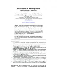
gular measurement can be achieved by optimizing the incident wavelengths. This is consistent with our other recent work in the application of the SPR technique to temperature measurements.7 The experimental setup, as depicted in Fig. 1, is identical to that used in Ref. 7. This is slightly different from the one used previously in Ref. 8, in that several laser wavelengths are used in our experiment. The light from the source is introduced through a polarizer into an electro-optic modulator (ConOptics) with the fast axis in the horizontal direction and then reflected from a 45°-45°-90° triangular fused-quartz prism with refractive index n = 1.4584 that is coated with a thin metal (Ag) film. The laser light then goes through analyzer ANt. Both the transmission axis of the polarizer and analyzer are at 45° relative to the horizontal direction. The light is then detected by a photodetector, and the converted electric signal from the photodetector is phase locked by a lock-in amplifier (Stanford Research SR830). A sawtooth signal is applied to the electro-optic modulator, and the sawtooth voltage is used as the phase-locking reference. By measuring the signal intensity and by
Fig. 1. Experimental setup of phase detection system. P, polarizer; ANt, analyzer; Dt, photodetector. © 2005 Optical Society of America
2728
OPTICS LETTERS / Vol. 30, No. 20 / October 15, 2005
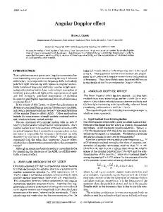
assuming almost unity reflectivity for the s wave, the relative phase difference between the p and the s waves arriving at the photodetector can finally be calculated by using Jones calculus.7 The relative phase 共p − s兲 can also be computed theoretically by using the standard Fresnel formulas. Figure 2(a) shows the theoretical results as a function of incident angle for four different wavelengths of light. The Ag film thickness is fixed at 50 nm, and the optical constants are taken from Ref. 7, in which these constants were fitted by using the Drude model. In Fig. 2(b) we also show the enhancement factor ␥ of the corresponding curves in Fig. 2(a). This enhancement factor ␥ is defined as the absolute value of the slopes: ␥ = 兩 / 兩, where is the relative phase and is the angle of incidence. The resolution of the angle measurement can be determined to be ⌬ = ⌬ / ␥, where ⌬ and ⌬ are the measurement resolutions for the angle of incidence and for the lock-in amplifier, respectively. The minimum increment of is fixed at 0.02° for the experiment. Since the angular resolution of the lock-in amplifier ⌬ is 0.01° and the enhancement factor ␥ is larger than 1, the resolution of the angular measurement can be larger than that of the lock-in amplifier. The larger the enhancement
Fig. 2. Theoretical results: (a) relative phase 共p − s兲; (b) the corresponding enhancement factor ␥ as a function of incidence angle for four different wavelengths of light.
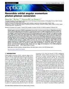
factor ␥ that we can obtain, the better the resolution of the angular measurement. From the simulation results, two phase change behaviors are observed with a critical wavelength c ⬃ 900 nm. In case (i), wavelengths below c, the overall phase change is about 360° across the SPR resonance angle; in case (ii), for wavelengths above c, the corresponding overall phase change is close to 0°. This phenomenon has been well established in the literature,7,9,10 and was previously explained in detail by use of a plot of the imaginary versus the real part of the p-wave reflection amplitude, in which the two cases mentioned above were clearly demonstrated for incident wavelengths both below and above the critical value.7 It should also be noted that the behaviors in the two cases can be the converse for other thickness values of the Ag film. Furthermore, from the results for the enhancement factor ␥, it is seen that for case (i) a longer incident wavelength will lead to steeper slopes and larger ␥, whereas for case (ii) the opposite behavior is seen. Hence one may expect that finer resolution in angular measurement can be attained by using longer wavelengths below c, but once c is exceeded, optimization takes the other direction. In the following, we are going to illustrate this effect by carrying out some measurements at the four wavelengths used in the theoretical calculations in Fig. 2. Figure 3 shows the corresponding measurements of the relative phase and the enhancement factor ␥ for the four wavelengths, with two above and two below c. The resonant angles of the SPR excitation in Fig. 3(a) have been verified independently by reflectance measurements. From Fig. 3(b), the peak value of the enhancement factor ␥ at 945 nm incident wavelength reaches a value of almost 5380, implying that the best resolution of the angular measurement in the present experiment can be as small as 1.9 ⫻ 10−6 deg, which is an order of magnitude smaller than previously reported values.8 Figure 4 shows the simulated maximum enhancement factor ␥ as a function of incident wavelength, from which the role of the critical wavelength can be clearly seen. We have also plotted the four data obtained in our experiment in Fig. 4. It is seen that, just like the comparison between the theoretical and the experimental results in Figs. 2 and 3, only qualitative agreement was obtained in our present work between theory and experiment. This is likely due to the uncertainty of many factors, which include the exact value of the Ag film thickness, possible oxidation of the film, the accuracy of the optical constants9,10 used in the simulation, and the limitation of the resolution of the measurements close to resonance. In addition, the imperfect nature (e.g., roughness) of the film will also lead to much lower values for the enhancement factor, as is well known in the case of intensity interrogation.1 But within these limitations, we think that both our simulation and our experimental data confirm the effect that we are trying to demonstrate, that is, the existence of a critical wavelength and the way to optimize these angular measurements by controlling the incident wavelengths. We note that there is still room for further optimization
October 15, 2005 / Vol. 30, No. 20 / OPTICS LETTERS
2729
however, to demonstrate the existence of such a wavelength by fixing the film thickness at a value close to the optimal one. In this work, we have demonstrated, both theoretically and experimentally, that the recent finely resolved angular measurement8 by SPR heterodyne interferometry can be further improved by optimizing the incident wavelengths for the optical excitation of the surface plasmon. One just has to be aware of whether the wavelength used is above or below a certain critical value, across which the phase change behavior flips from one pattern to another. The physical origin of this crossover behavior in the phase as a function of incident angle is complicated7; it depends crucially on two damping rates of the surface plasmon, namely, the internal damping and the radiative damping as defined in Ref. 1. It can be argued that in the case with smaller internal damping the longer incident wavelength will definitely lead to finer resolution in the angular measurement.7 In our present study we have obtained a resolution down to 1.3 ⫻ 10−6 deg from our simulation and down to 1.9 ⫻ 10−6 deg from our measurement with the incident wavelength set at 945 nm. As a final remark, we point out that such fine measurement is not diffraction limited, since it is the relative phase change between the s and the p waves that is being monitored, and the fine angular resolution is obtained by a calibration of these measured phase shifts. Hence the worry that the uncertainty principle may lead to a requirement for optical systems of huge dimensions is not a concern in our experiment.
Fig. 3. Experimental results: (a) relative phase 共p − s兲; (b) the corresponding enhancement factor ␥ as a function of incidence angle for the four wavelengths used in Fig. 2.
H.-P. Chiang acknowledges financial support from the Center of Nanostorage Research, National Taiwan University, under grant MOEA 93-EC-17-A-08S1-0006 and from the National Science Council of the Republic of China under grants NSC 93-2112-M-019002 and NSC 93-2120-M-019-001. H.-P. Chiang’s e-mail address is
[email protected]. References
Fig. 4. Theoretical and experimental results for the maximum enhancement factor ␥ as a function of incident wavelength.
of the resolution by adjusting the Ag film thickness.1 One has just to bear in mind that the value of the critical wavelength will change when the film thickness varies. The main goal of our present work is,
1. H. Raether, Surface Plasmons on Smooth and Rough Surfaces and on Gratings (Springer, 1988). 2. See, e.g., J. Homola, Anal. Bioanal. Chem. 377, 528 (2003). 3. See, e.g., L. S. Jung, C. T. Campbell, T. M. Chinowsky, M. N. Mar, and S. S. Yee, Langmuir 14, 5636 (1998). 4. S. Herminghaus and P. Leiderer, Appl. Phys. Lett. 58, 352 (1991). 5. S. Herminghaus and P. Leiderer, Appl. Phys. A 51, 350 (1990). 6. B. Chadwick and M. Gal, Jpn. J. Appl. Phys. Part 2 32, 2716 (1993). 7. H.-P. Chiang, H.-T. Yeh, C.-M. Chen, J.-C. Wu, S.-Y. Su, R. Chang, Y.-J. Wu, D. P. Tsai, S. U. Jen, and P. T. Leung, Opt. Commun. 241, 409 (2004). 8. J. Guo, Z. Zhu, W. Deng, and S. Shen, Opt. Eng. 37, 2998 (1998). 9. A. V. Kabashin, V. E. Kochergin, A. A. Beloglazov, and P. I. Nikitin, Biosens. Bioelectron. 13, 1263 (1998). 10. P. I. Nikitin, A. A. Beloglazov, V. E. Kochergin, M. V. Valeiko, and T. I. Ksenevich, Sens. Actuators B 54, 43 (1999).