High-Resolution Imaging with High-Frequency 1-D Linear CMUT Arrays ¨ David T. Yeh, Omer Oralkan, Ira O. Wygant, A. Sanli Ergun, Jeremy H. Wong, and Butrus T. Khuri-Yakub Edward L. Ginzton Laboratory Stanford University, Stanford, CA 94305–4088 Email:
[email protected]
Abstract— High frequency ultrasound arrays allow dynamic focusing and shorter scan times, but the dimensions required at high frequencies present stringent challenges to current ultrasound array fabrication technology. Using CMUTs facilitates building high frequency linear arrays, as demonstrated by a collapse-mode array (20 MHz) with 50- µm element pitch and two conventional-mode arrays (26 MHz and 41 MHz) with 36µm element pitch. The fractional bandwidths are 85%, 52%, and 32% respectively; the narrow bandwidths are due to low fill factor. Thirty-two elements of the arrays were used for imaging line targets. In addition, B-scans of a rabbit eye are shown.
I. I NTRODUCTION High frequency ultrasound is used in applications that require high resolution and when deep penetration is not necessary. Existing high frequency ultrasound is based upon a single-element fixed-focus transducer that is mechanically scanned over the area to be imaged. Linear arrays enable, among other benefits, dynamic focusing and obviate the need for mechanical scanning, thereby improving resolution and reducing scan times. To avoid grating lobes at high frequencies, the element pitch must be very small, and this presents great challenges for fabricating high frequency linear arrays. Several high frequency linear arrays have been reported in the literature, including a 30-MHz linear array with 48 elements and a pitch of two wavelengths [1], and a lasermicromachined 40-MHz linear array with 16 elements and one wavelength pitch [2]. Another approach is to fabricate kerfless arrays [3]. Capacitive micromachined ultrasonic transducers (CMUTs) are particularly suited for high frequency arrays because the fabrication process used is routinely able to produce features several microns in size. This paper extends previously reported work [4], [5] by presenting initial imaging results using high frequency CMUT transducers. II. CMUT L INEAR A RRAYS Three CMUT arrays from a single wafer made using the silicon nitride process were used for the imaging experiments. Common device parameters are the following: membrane thickness, 0.4 µm; electrode thickness, 0.3 µm; gap distance, 0.2 µm. Individual parameters for the designs are listed in Table I. These arrays have high element count (64 to 128 elements) and very small element pitch (36 µm to 50 µm). One parameter for adjusting the operating frequency of a CMUT is the cell radius. Making the radius small increases
TABLE I CMUT D ESIGN AND O PERATING PARAMETERS
Design Mode of operation
1
2
3 conv
collapse
conv
Membrane radius (µm)
9
6
5
Cells per element
80
110
110
Element pitch (µm)
50
36
36
Elements in array
64
128
64
CMUT bias, Vbias (V)
90
100
100
Pulse width, T (ns)
20
22
16
Center frequency in immersion (MHz)
20
26
41
V_bias
T
25 V TX CMUT
RX × 32
1: 32
SRS DG535
:12 3
ert up m oC oT
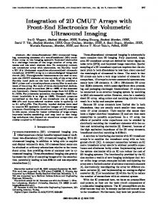
HP Infinium 54825A Fig. 1. Block diagram of 32-channel data acquisition system for synthetic phased array imaging.
the frequency. Another way to increase the frequency of the CMUT is to operate it in collapse mode [6], as is the case for Design 1. III. E XPERIMENTAL S ETUP Thirty-two channels of the CMUT were used in the data acquisition system outlined in Fig. 1. To interface with the CMUT, two front-end integrated circuits were wire bonded to the CMUT in a pin grid array package, as shown in Fig. 2. Although this arrangement is capable of full phased array operation, synthetic phased array imaging was performed to simplify the data collection for this demonstration. The CMUT was biased with a voltage Vbias , and elements were excited one at a time with a 25-V pulse of width T , both given in Table I for each design. A-scans were acquired from the entire array for each transmit element using a sampling rate of 500 MS/s.
Voltage (mV)
20
(b)
0
-20 6.3
6.4
6.5
6.6 6.7 Time (µs)
6.8
6.9
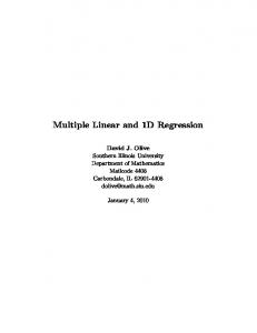
Fig. 2. (a) Linear array wire bonded to two front end ICs in PGA package. (b) 128-element CMUT linear array (Design 2). (c) 16-channel front end IC
The front-end circuit, a higher frequency version of the one presented in [7], is a custom IC fabricated in a high voltage BiCMOS process and is used for prototyping with high frequency CMUTs. Each IC contains 16 channels of independent pulser/amplifier circuits capable of performing within specifications for transducers with capacitance less than 2.5 pF. The pulser is a level-shifter circuit using high voltage CMOS transistors that are stacked to increase the voltage handling limit. It can produce up to a 27-V unipolar pulse with a width of 20 ns. A high voltage CMOS transistor acts as a switch that protects the amplifier during the pulsing. The amplifier employs a transimpedance feedback topology to amplify and buffer the signal from the CMUT and provides 25 kΩ of gain with a bandwidth of at least 30 MHz. IV. R ESULTS
0 -10 -20 -30 -40 -50 0
5
10
15
20 25 30 Frequency (MHz)
35
40
45
(b) Fig. 3. 20 MHz array, collapse mode, plane reflector at 4.9 mm, 16 avg.: (a) A-scan; (b) FFT.
Voltage (mV)
(c)
20 0 -20 1.7
1.8
1.9
2 2.1 Time (µs)
2.2
2.3
2.4
(a) Normalized Magnitude(dB)
(a)
Normalized Magnitude(dB)
(a)
A. A-Scan results
0 -10 -20 -30 -40 -50 0
5
10
15
20 25 30 Frequency (MHz)
35
40
45
(b) Fig. 4. FFT.
26 MHz array, plane reflector at 1.5 mm, 0 avg.: (a) A-scan; (b)
20
Voltage (mV)
A-scans of a plane reflector (the oil-air interface) were acquired. The plots of the time domain pulse-echo waveform and its FFT are shown for the three designs in Figs. 3, 4, and 5. Design 1 operates in immersion at 20 MHz with 85% fractional bandwidth, Design 2 at 26 MHz, 52% fractional bandwidth, Design 3 at 41 MHz, 32% fractional bandwidth. Designs 2 and 3 have narrower bandwidths than usual for CMUTS because their designs have low fill factor, as discussed below.
0
-20 0.8
0.9
1
1.1 1.2 Time (µs)
z
(mm) Normalized Magnitude(dB)
4 3 2 1
Fig. 6.
-1
0 1 (mm)
4 wire phantom for imaging experiments.
1.4
1.5
(a)
5
-y
1.3
0 -10 -20 -30 -40 -50 0
10
20
30 40 Frequency (MHz)
50
60
(b)
y
Fig. 5. FFT.
41 MHz array, plane reflector at 0.75 mm, 16 avg.: (a) A-scan; (b)
5 4.5
4
4
3.5
3.5 Z (mm)
Z (mm)
5 4.5
3 2.5
3 2.5
2
2
1.5
1.5
1
1
0.5
0.5 −3
−2
−1
0 Y (mm)
1
2
3
−3
−2
−1
(a)
5
5 4.5
4
4
3.5
3.5
3 2.5
3
2
2 1.5
1
1
0.5
0.5 −2
−1
0 Y (mm)
1
2
3
−3
−2
−1
(a)
1
2
3
2
3
B-scans from the 26-MHz transducer, 40 dB, 16 averages: (a) 4 glass fibers; (b) 4 nylon lines.
5
5
4.5
4.5
4
4
3.5
3.5
3 2.5
3 2.5
2
2
1.5
1.5
1
1
0.5
0.5 −2
0 Y (mm)
(b)
Z (mm)
Z (mm)
Fig. 8.
−1
0 Y (mm)
1
2
3
(a) Fig. 9.
3
2.5
1.5
−3
2
B-scans from the 20-MHz transducer (collapse mode), 40 dB, 0 averages: (a) 4 glass fibers; (b) 4 nylon lines.
4.5
−3
1
(b)
Z (mm)
Z (mm)
Fig. 7.
0 Y (mm)
−3
−2
−1
0 Y (mm)
1
(b)
B-scans from the 41-MHz transducer, 40 dB: (a) 4 glass fibers, 16 averages; (b) 4 nylon lines, 64 averages.
B. B-scan imaging Offline image reconstruction generated B-scans using the synthetic phased array imaging technique with focusing on transmit and receive. The elements were normalized for variations in amplitude, but otherwise no apodization was applied. A target made of lines positioned as shown in Fig. 6 was imaged to characterize imaging performance. B-scans were made of both a nylon target, which has an acoustic impedance mismatch to oil of 2:1, and a glass fiber target with a mismatch
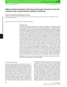
of 10:1. The nylon lines were 76 µm in diameter, and the glass fibers, 150 µm. The B-scans are shown in Figs. 7, 8, and 9. Finally, B-scans were made of a rabbit eye. Fig. 10 shows the cross section of a rabbit eye and the relative size and location of the transducer aperture. Figs. 11 and 12 show the B-scans of the rabbit eye using the Design 1 transducer operated in conventional (10 MHz) and collapse modes (20 MHz), respectively.
EXTRINSIC EYE MUSCLES
18
IRIS
16 14
CORNEA
12
LENS
Z (mm)
TRANSDUCER APERTURE VITREOUS BODY
10 8 6 4
ANTERIOR CHAMBER
2 RETINA
POSTERIOR CHAMBER
−10
SCLERA ~ 3 mm
Fig. 10.
~ 7 mm
Fig. 12.
~ 9 mm
5
10
B-scan of rabbit eye, 20 MHz, 16 avg., 70 dB dynamic range.
potential of using CMUTs in high frequency arrays. Current work involves expanding the prototype system to utilize more channels of the array. High frequency CMUT arrays can also enable novel applications that require very small transducer dimensions. One such application is monitoring the RF ablation procedure in the heart with intracardiac ultrasound. Such a transducer is mounted on the distal tip, which forces a limited aperture size. CMUTs can be used to make fine pitch linear arrays that operate at high frequencies and are especially appropriate for new applications of high frequency ultrasound.
16 14 12 Z (mm)
0 Y (mm)
Cross-section of rabbit eye drawn to scale.
18
10 8 6 4 2 −10
Fig. 11.
−5
−5
0 Y (mm)
5
10
B-scan of rabbit eye, 10 MHz, 16 avg., 76 dB dynamic range.
V. D ISCUSSION A. A-scan results Design 1 operates in collapse mode and shows good output pressure and bandwidth. Designs 2 and 3 exhibit bandwidths that are narrower than usual for CMUTs because they have low fill factors (the ratio of transducer active area to total area). This issue was known at the time of design and was discussed in [4]. High frequency transducers with higher fill factors, such as those made using the wafer-bonding process, have wider bandwidth and have been reported in [5]. B. B-scan imaging Using 32 elements of the CMUT array results in an imaging aperture that is very small. Consequently, many features of the eye commonly seen in images from single element transducers that scan the entire imaging area are absent. Widening the aperture by increasing the channel count would improve resolution and the lateral extent of the features seen. Given the small aperture, the result is very promising in terms of both penetration and resolution. VI. C ONCLUSION Images from high frequency CMUT linear arrays operating between 20 and 40 MHz have been shown, demonstrating the
ACKNOWLEDGMENT This work was supported by the National Institutes of Health. Sean Hansen designed and fabricated the arrays. Thanks to Bill Broach and the Portable Power group at National Semiconductor Corporation for supporting us with assistance in circuit design and for providing the custom integrated circuits. David Yeh is supported by a National Defense Science and Engineering Graduate Fellowship. R EFERENCES [1] T. A. Ritter, T. R. Shrout, R. Tutwiler, and K. K. Shung, “A 30MHz piezo-composite ultrasound array for medical imaging applications,” IEEE Trans. Ultrason., Ferroelect., Freq. Contr., vol. 49, no. 2, pp. 217– 230, Feb. 2002. [2] M. Lukacs, M. Sayer, G. Lockwood, and S. Foster, “Laser micromachined high frequency ultrasonic arrays,” in Proc. IEEE Ultrason. Symp., 1999, pp. 1209–1212. [3] C. E. Morton and G. R. Lockwood, “Evaluation of kerfless linear arrays,” in Proc. IEEE Ultrason. Symp., 2002, pp. 1257–1260. ¨ Oralkan, S. Hansen, B. Bayram, G. Yaralioglu, A. Ergun, and B. Khuri[4] O. Yakub, “High-frequency CMUT arrays for high-resolution medical imaging,” in Proc. IEEE Ultrason. Symp., 2004, pp. 399–402. ¨ Oralkan, A. S. Ergun, X. Zhuang, I. O. Wygant, and B. T. [5] D. T. Yeh, O. Khuri-Yakub, “High-frequency CMUT arrays for high-resolution medical imaging,” in Proc. SPIE Medical Imaging 2005: Ultrasonic Imaging and Signal Processing, vol. 5750, 2005, pp. 87–98. [6] B. Bayram, E. Hæggstr¨om, G. G. Yaralioglu, and B. T. Khuri-Yakub, “A new regime for operating capacitive micromachined ultrasonic transducers,” IEEE Trans. Ultrason., Ferroelect., Freq. Contr., vol. 50, no. 9, pp. 1184–1190, Sept. 2003. ¨ Oralkan, A. S. [7] I. O. Wygant, D. T. Yeh, X. Zhuang, A. Nikoozadeh, O. Ergun, M. Karaman, and B. T. Khuri-Yakub, “A miniature real-time volumetric ultrasound imaging system,” in Proc. SPIE: Medical Imaging 2005: Ultrasonic Imaging and Signal Processing, vol. 5750, 2005, pp. 26–36.