Tamkang Journal of Science and Engineering, Vol. 9, No 1, pp. 37-44 (2006)
37
High-Speed Transition Detecting Circuits for On-Chip Interconnections Hong-Yi Huang1 and Shih-Lun Chen2* 1
VLSI/CAD Laboratory, Department of Electronic Engineering, Fu-Jen Catholic University, Taiwan 242, R.O.C. 2 Nanoelectronics and Gigascale Systems Laboratory, Institute of Electronics, National Chiao-Tung University, Hsin-Chu, Taiwan 300, R.O.C.
Abstract A transient sensitive trigger (TST) was used to reduce the RC delay time of the long interconnection in deep sub-micron (DSM) processes. The conventional TST circuit exhibits a voltage drop in threshold voltage during transitions, extending the delay time. This paper proposes new circuits called transition detecting circuits (TDCs) to overcome the drawbacks of the conventional TST. The proposed circuits yield 45-74% shorter delay time than the conventional TST simulation using a 0.25 mm CMOS process. The experiment results also show that the proposed TDCs are faster than the conventional TST. The proposed circuits can be applied to receiving long interconnect signals in high-speed VLSI design. Key Word: High-Speed, Interconnections, Receivers, Deep Sub-Micron, Transition Detection
1. Introduction The development of semiconductor manufacturing processes has reduced the sizes of devices. This trend decreases the gate delay of the integrated circuit. On one hand, more devices are being integrated in a single chip. On the other hand, a single chip contains a whole system, increasing the area of the chip. The trend results in longer wires between devices as the chips become larger. However, the interconnections are scaled down largely in the horizontal dimension as the process is scaled down, and the vertical dimension is only slightly scaled down. Hence, the interconnect delay dominates the whole chip delay in current VLSI [1-3]. Several modern technologies have been applied to reduce the interconnect delay. Aluminum used in the interconnections can be replaced with less resistive metals, such as copper. Substances with a lower dielectric constant (low-k) can be used as inter-level dielectric materi*Corresponding author. E-mail:
[email protected]
als [4, 5]. Therefore, the parasitic resistance and capacitance of the wire can be reduced. Inserting repeaters (buffers) can also reduce the interconnect delay [6-8]. However, the repeaters are large devices so that it may consume more power and require a large chip area. Besides, inserting repeaters requires a CAD tool to determine their positions. Using a special receiver to receive the long interconnect signal also efficiently reduces the interconnect delay [9-12]. The other method is to insert an accelerator [10] in the middle of the interconnection to increase the driving current in the long wire. A transient sensitive trigger (TST) reported in [10] was used to reduce the RC delay time of the long interconnection. The conventional TST circuit exhibits a voltage drop in threshold voltage during transitions resulting in longer delay time. This paper proposes three new circuits to solve the problem of the conventional TST [10] and to reduce the long interconnect delay [13]. The rest of this paper is organized as follows. Section 2 analyzes the problem of the conventional TST. The speed limitation of the TST is also considered. Section 3 pres-
38
Hong-Yi Huang and Shih-Lun Chen
ents the proposed transition detection circuits (TDCs). Section 4 compares the simulation and experiment results. The final section draws some conclusions.
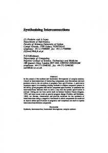
2. Problem of Conventional Transient Sensitive Trigger Figure 1 depicts the circuit diagram of the conven-
Figure 1. Transient sensitive trigger (TST) [10].
tional transient sensitive trigger (TST) [10]. Figure 2 plots the waveforms of the TST. Initially, nodes IN and CO are assumed to be at VDD and node OUT is assumed to be at GND. The source and the gate voltages of the transistor N2 are VDD. The transistor N2 remains off at this moment. After the node IN makes a highto-low transition between time t1 to t2, shown in Figure 2, node INP does not immediately follow. As node IN is pulled down to VDD-Vtn, the Vgs of the transistor N2 exceeds Vtn, turning on transistor N2. Finally, node INP follows IN and starts to be pulled down. The drawback of the TST is that node INP must wait till node IN has a voltage drop Vtn to turn on transistor N2. The signal INP is delayed for time (t2-t1) before turning on transistor N2. Control signal COB is delayed by a Schmitt Trigger circuit, which also receives signal IN. At time t3, control signal CO makes a high-to-low transition, turning on transistors P2 and P3 and turning off transistors N2 and N3. Then, the internal nodes are set to the required initial state. The TST is ready to receive the next low-to-high transition of node IN. As node IN makes a low-to-high transition, the TST undergoes the required threshold voltage drop between t4 to t5 to turn on transistor P2. Hence, the speed of the conventional TST is limited.
3. Transition Detecting Circuits
Figure 2. Waveforms of the conventional TST.
The proposed transition detecting circuit (TDC), shown in Figure 3, is similar to the conventional TST circuit shown in Figure 1, except in that transistors N2 and P2 are interchanged and the control signals are inverted. Figure 4 plots the waveforms of the TDC shown in Figure 3. Initially, the initial states of nodes IN and CO are assumed to be at VDD and that of nodes OUT and COB are assumed to be at GND. At this moment, |Vgs| of transistor P2 is VDD, which greatly exceeds |Vtp|. As node IN makes a high-to-low transition, node INP follows node IN immediately through transistor P2. Similarly, as node IN makes a low-to-high transition, node INN immediately follows node IN through transistor N2. Therefore, the TDC in Figure 3 overcomes the
High-Speed Transition Detecting Circuits for On-Chip Interconnections
drawback of the TST in Figure 1. However, the voltage swings at nodes INP and INN are from VDD to |Vtp| and from VDD- Vtn to GND, respectively. The reduced swings result in a lower |Vgs| of transistors P4 and N4 and a lower output driving current. Thus, the speed can
Figure 3. Transition detecting circuit, type-1.
Figure 4. Waveforms of the TDC in Figure 3.
39
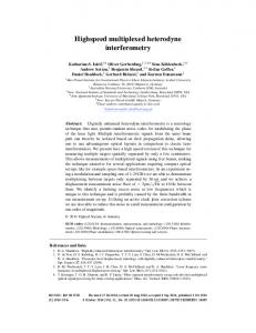
be limited if the output load of the TDC is large. Figure 5 depicts another transition detecting circuit of type-2. The proposed circuit in Figure 5 combines the circuit in Figure 1 and the circuit in Figure 3. Two complementary transmission gates TR1 and TR2 are used to replace transistors N2 and P2 in Figure 1 or to replace transistors P2 and N2 in Figure 3. Therefore, the transitions of nodes INN and INP in Figure 5 follow the transition of node IN. Moreover, they exhibit a full voltage swing of nodes INN and INP. In addition, the output current of the TDC in Figure 5 is not limited. Figure 6 depicts the other transition detecting circuit of type-3. The proposed circuit in Figure 6 consists of the circuit in Figure 3 and two feedback paths. The feedback-control accelerating devices, which consist of transistors P5, P6, N5 and N6, are used to form feedback paths from node OUT to node INP and node OUT to node INN, respectively. Figure 7 plots the waveforms of the TDC shown in Figure 6. At time t1, node IN starts to make a high-to-low transition, and node INP immediately follows node IN. At time t2, the voltage at node OUT is high enough to turn on transistor N6. Therefore, another pull-down path of node INP is generated through transistors N6 and N5 to GND. At time t3, control signals
Figure 5. Transition detecting circuit, type-2.
40
Hong-Yi Huang and Shih-Lun Chen
CO and COB make transitions to turn on transistor P3 and turn off transistor N3. At time t4, node IN starts to make a low-to-high transition, and node INN immediately follows node IN. At time t5, the voltage at node OUT is low enough to turn on transistor P6. Therefore, another pull-up path of node INN is generated through transistors P6 and P5 to VDD. At time t6, control signals CO and COB make transitions to turn on transistor N3 and turn off transistor P3. Using the accelerating circuit, full voltage swings are generated at nodes INN and INP. Furthermore, transitions at nodes INP and INN are accelerated through the feedback paths. Figure 7 indicates that node INP makes a sharp transition at t2 and node INN makes a sharp transition at t5, because of the feedback accelerating paths, increasing the speed of transmission of node IN to nodes INP and INN.
W/mm and 0.239 pF/mm, respectively. Figure 9 shows the simulated delays for interconnections of different lengths. The delay is measured from node IN to node OUT, as shown in Figure 8. The inverter is sized to its optimum delay performance. As shown in
4. Experiment Results A 1P5M 0.25 mm CMOS device model is used for SPICE simulation. Figure 8 depicts the benchmark circuit that consists of a driver, a three-segment RC wire model and a receiver. The driver is a simple static inverter. The parasitic resistance and capacitance of the metal-1 wire in the 0.25 mm CMOS process are 238
Figure 7. Waveforms of the TDC in Figure 6.
Figure 6. Transition detecting circuit, type-3.
High-Speed Transition Detecting Circuits for On-Chip Interconnections
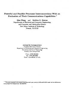
Figure 9, the delay of the proposed circuits (Figures 3, 5 and 6) is shorter than that of the conventional TST. Table 1 compares the gate delays of the conventional TST and the proposed TDCs. The gate delays are measured from the receiver input to the receiver output. Compared to the conventional TST, the TDCs in Figures 3, 5, and 6 re-
41
duce the gate delay by 47%, 45% and 74%, respectively. Figure 10 shows the power consumption for different lengths of interconnection. The power consumption includes that of the interconnection, the driver and the receiver. The frequency of the input signal is chosen to be 12.5 MHz to guarantee a full-voltage swing at the input node IN of the receiver. The power consumption of the conventional TST and the TDCs exceeds that of the static inverter because the control signal of the conventional TST and the TDCs is generated by a Schmitt Trigger cir-
Figure 8. Three segment RC distributed elements of wire for simulation.
Figure 10. Power consumption for interconnections of various lengths.
Figure 9. Delays for interconnections of various lengths.
Table 1. Gate delay for different receivers Figure 1 Figure 3 Figure 5 Figure 6 Inverter
Gate delay (ps)
Normalized
380 200 210 130 780
1.00 0.53 0.55 0.26 2.05
Figure 11. Delays obtained with different TSAs.
Table 2. Comparisons of the conventional TST and the TDCs Figure 1 Figure 3 Figure 5 Figure 6 Inverter
Speed
Power
Area
Internal Swing
Good Better Better Excellent Poor
Good Good Good Good Excellent
Good Good Good Good Excellen
Full-swing Not full-swing Full-swing Full-swing -
42
Hong-Yi Huang and Shih-Lun Chen
Figure 12. Photograph of the test chip.
Figure 13. Measured waveforms and delays.
High-Speed Transition Detecting Circuits for On-Chip Interconnections
cuit that has large short-circuit current. In [10], the conventional TST is applied to generate a transient sensitive accelerator (TSA) that accelerates the long interconnect signal. Figure 11 compares the delays obtained with different TSAs using the TST and the TDCs. The TSAs that use the TDCs are faster than the conventional TSA. Table 2 compares the characteristics of the TST and the TDCs. The TDC in Figure 6 performs best in terms of speed and power dissipation. Compared to the static inverter, the TDCs may require more devices, increasing the chip area and the power dissipation. However, the increased area and power represent only a very small overhead for a large chip. Figure 12 shows the photograph of the test chip. The test chip was implemented in a 0.25 mm 1P5M CMOS process. The area of the test chip including the I/O pads is 730 ´ 850 mm2. In this test chip, the conventional TST (Figure 1) and the proposed circuits (Figures 3, 5 and 6) are used to receive the 10 mm metal-1 wire signals. The measured delays, including the wire, input and output buffers delays are shown in Figure 13. The measured delays are 9.15 ns, 8.05 ns, 7.95 ns and 7.45 ns for the circuits shown in Figures 1, 3, 5 and 6, respectively. The simulation delays of input and output buffers are 3.82ns totally. The net delay of the circuits in Figures 1, 3, 5 and 6, not including the buffers delay are 5.33 ns, 4.23 ns, 4.13 ns and 3.62ns, respectively. The results are very close to the simulation of 10mm wires shown in Figure 9. It is verified that the proposed schemes are faster than the conventional TST.
5. Conclusions Three transition detecting circuits (TDCs) are proposed in this paper. The proposed TDCs overcome the drawback of the conventional TST. The proposed circuits are proven to perform faster than the conventional TST. The proposed TDCs have a 45-74% delay reduction than the conventional TST simulated using a 0.25 µm CMOS process. A test chip is implemented. The experiment results also show that the proposed circuits are faster than the conventional TST. The overheads of area and power dissipation are very small for a large chip. The
43
proposed TDCs can be applied to receive long interconnect signals in a high-speed VLSI design. Besides, the proposed TDCs are well suited to constructing an accelerator to of the interconnect signal than that of the conventional TST.
Acknowledgement The authors would like to thank the National Science Council of the Republic of China for financially supporting this research under Contract No. NSC89-2215-E030-005.
References [1] Sarawat, K. C. and Mohammadi, F. “Effect of Scaling of Interconnections on the Time Delay of VLSI Circuits,” IEEE J. Solid-State Circuits, Vol. SC-17, pp. 275-280 (1982). [2] Nassif, S., “Delay Variability: Sources, Impacts and Trends,” Tech. Dig. IEEE International Solid-State Circuits Conf., pp. 368-369 (2000). [3] Davis, J. A., Venkatesan, R., Kaloyeros, A., Beylansky, M., Souri, S. J., Banerjee, K., Saraswat, K. C., Rahman, A., Reif, R. and Meindl, J. D., “Interconnect Limits on Gigascale Integration (GSI) in the 21st Century,” Proceedings of IEEE, Vol. 89, pp. 305-324 (2001). [4] Zhao, Bin “Advanced Interconnect Systems for ULSI Technology,” Proc. IEEE International Conf. on Solid-State and Integrated Circuits, pp. 43-46 (1998). [5] Miyamoto, M., Takeda, T. and Furusawa, T., “Highspeed and Low-power Interconnect Technology for Sub-quarter-micron ASIC’s,” IEEE Trans. Electron Devices, Vol. 44, pp. 250-256 (1997). [6] Dhar, S. and Franklin, M. A., “Optimum Buffer Circuits for Driving Long Uniform Lines,” IEEE J. Solid-State Circuits, Vol. 26, pp. 32-40 (1991). [7] Jiang, Y., Sapatnekar, S. S. and Sarto, E., “Interleaving Buffer Insertion and Transistor Sizing into a Single Optimization,” IEEE Trans. VLSI Systems, Vol. 6, pp. 625-633 (1999). [8] Ismail, Y. I., Friedman, E. G. and Neves, J. L., “Repeater Insertion in Tree Structured Inductive Interconnect,” IEEE Trans. Circuits and Systems-II: Analog and Digital Signal Processing, Vol. 48, (2001).
44
Hong-Yi Huang and Shih-Lun Chen
[9] Colshan, R. and Jaroun, B., “A Novel Reduced Swing CMOS BUS Interface Circuit for High Speed Low Power VLSI Systems,” Proc. IEEE International Symp. on Circuits and Systems, Vol. 4, pp. 351-354 (1994). [10] Iima, T., Mizuno, M., Horiuchi, T. and Yamashina, M., “Capacitor Coupling Immune, Transient Sensitive Accelerator for Resistive Interconnect Signals of Subquarter Micron ULSI,” IEEE J. Solid-State Circuits, Vol. 31, pp. 531-536 (1996). [11] Zhang, H., George, V. and Rabaey, J. M., “Low-swing on-chip Signaling Techniques: Effectiveness and Ro-
bustness,” IEEE Trans. VLSI Systems, Vol. 8, pp. 264272 (2000). [12] Huang, H.-Y. and Chen, S.-L., “Input Isolated Sense Amplifiers,” Proc. IEEE International Symp. on Circuits and Systems, Vol. 4, pp. 587-590 (2000). [13] Huang, H.-Y. and Chen, S.-L., “High-speed Receivers for On-chip Interconnections in Deep-submicron Process,” Proc. IEEE International Conf. on Electrons, Circuits, and Systems, pp. 769-772 (2002).
Manuscript Received: Mar. 29, 2005 Accepted: May. 24, 2005