Feb 23, 2010 - put Bayesian computing machine (BCM) capable of evalu- ating probabilistic ... FPGA-based special-purpose processor, for computing the.
High-Throughput Bayesian Computing Machine with Reconfigurable Hardware Mingjie Lin, Ilia Lebedev, and John Wawrzynek Department of Electrical Engineering and Computer Science University of California at Berkeley, CA 94704
{mingjie.lin, ilial, johnw}@berkeley.edu ABSTRACT
1.
We use reconfigurable hardware to construct a high throughput Bayesian computing machine (BCM) capable of evaluating probabilistic networks with arbitrary DAG (directed acyclic graph) topology. Our BCM achieves high throughput by exploiting the FPGA’s distributed memories and abundant hardware structures (such as long carry-chains and registers), which enables us to 1) develop an innovative memory allocation scheme based on a maximal matching algorithm that completely avoids memory stalls, 2) optimize and deeply pipeline the logic design of each processing node, and 3) schedule them optimally. The BCM architecture not only can be applied to many important algorithms in artificial intelligence, signal processing, and digital communications, but also has high reusability, i.e., a new application needs not change a BCM’s hardware design, only new task graph processing and code compilation are necessary. Moreover, the throughput of a BCM scales almost linearly with the size of the FPGA on which it is implemented. A Bayesian computing machine with 16 processing nodes was implemented with a Virtex-5 FPGA (XCV5LX155T-2) on a BEE3 (Berkeley Emulation Engine) platform. For a wide variety of sample Bayesian problems, comparing running the same network evaluation algorithm on a 2.4 GHz Core 2 Duo Intel processor and a GeForce 9400m using the CUDA software package, the BCM demonstrates 80x and 15x speedups respectively, with a peak throughput of 20.4 GFLOPS (Giga Floating-Point Operations per Second).
We present a Bayesian computing machine (BCM), an FPGA-based special-purpose processor, for computing the many important algorithms in artificial intelligence and signal processing that can be represented as Bayesian probabilistic networks. These algorithms include the forward or backward algorithm, the Viterbi algorithm, the iterative “turbo” decoding algorithm, Pearl’s belief propagation algorithm, the Kalman filter, and certain fast Fourier transform (FFT) algorithms. Reminiscent of many-core processor designs, the BCM architecture we present consists of many processing nodes. However, unlike many-core architectures, the BCM achieves the maximum practically possible throughput from the logic fabric, allows more than 20 to 30 pipeline stages, and permits long-latency, low-bandwidth memory while achieving zero memory stalls. Although accelerating Bayesian network applications with reconfigurable hardware is not a new idea, we believe our work is novel in several aspects. In addition to being high throughput, the BCM architecture is completely reusable and therefore applicable in a wide range of Bayesian network computing problems. More specifically, an implementation of the BCM can be applied to Bayesian problems with different size and/or graph topology, and works equally well for different kinds of applications. As long as the task graph of the new application is a DAG, only revised task graph processing and code compilation are needed while the FPGA implementation of the BCM can remain the same. Furthermore, the throughput of a BCM implementation scales almost linearly with the size of FPGA on which it is implemented, provided the CAM structure in the memory allocator scales with the number of processing nodes. As shown in Section 6.2, this can be achieved by designing a processing array structure that computes maximal matching efficiently and allows pipelining easily. The key technique we employ in the design of the BCM to achieve high throughput is to deeply pipeline processing nodes running in parallel. Typically in processor design, aggressive pipelining diminishes performance return due to hazards and memory misses. A major contribution of this work is to develop various techniques to overcome these issues. More specifically:
Categories and Subject Descriptors C.3 [Computer Systems Organization]: [Special-Purpose and Application-Based Systems]
General Terms Algorithm, Experimentation, Measurement, Performance
Keywords Reconfigurable Hardware, Bayesian Computing.
Permission to make digital or hard copies of all or part of this work for personal or classroom use is granted without fee provided that copies are not made or distributed for profit or commercial advantage and that copies bear this notice and the full citation on the first page. To copy otherwise, to republish, to post on servers or to redistribute to lists, requires prior specific permission and/or a fee. FPGA’10, February 21–23, 2010, Monterey, California, USA. Copyright 2010 ACM 978-1-60558-911-4/10/02 ...$10.00.
INTRODUCTION
1. We developed an algorithm to efficiently schedule pipelined processing nodes to avoid dependency from input data. To our knowledge, this work is the first formulation of optimal task scheduling where processors are pipelined with constant precedence delay.
2. We developed an innovative memory allocation scheme that exploits the deterministic pattern of incoming data items, which completely removes memory stalls. In particular, we have designed a processing array structure which allows efficient maximal matching and can be easily pipelined. 3. In contrast to conventional direct-address memory, our BCM uses a CAM-based approach to dynamically allocate memory and to perform fast queries. The CAM structures allow both memory allocation and memory scheduling.
1.1 Applications Many important applications exist for the Bayesian graphical model ([1], Chapter 8) and consequently can be greatly accelerated by the BCM. We now describe two seemingly unrelated applications—early vision and DNA pyrosequencing— in order to illustrate the wide applicability of the BCM architecture. The first application we consider is a group of early vision problems (such as stereo and image restoration), which are vital for many machine vision applications. It has been found recently that all those problems can be accurately solved with the belief propagation framework [2]. A special case of the sum-product algorithm, belief propagation [3] is a message passing algorithm for performing inference on graphical models, such as Bayesian networks and Markov random fields, whose core is calculating the marginal distribution for each unobserved node, conditional on any observed nodes. Although the belief propagation algorithm is conceptually straightforward, software implementations of this Bayesian inference algorithm for typical early vision problems are often too slow for practical use even with sophisticated algorithmic techniques [2]. More concretely, assuming 30 frames/second and 1.2M pixels per image frame for a typical early vision problem, [2] shows each pixel needs to perform 16 floating point operations on average for each inference iteration, which translates into the effective computing requirement of 0.6 GFLOPS for real-time processing— at least one order higher than a software implementation running on a modern processor. In contrast, as shown in Section 7, our BCM prototype can easily achieve effective throughput of about 20 GFLOPS. The second interesting application is DNA pyrosequencing— a special case of the sequencing-by-synthesis process. As in [4], non-idealities of a typical pyrosequencing run can be modeled as a noisy switched linear system parameterized by the unknown DNA sequence whose switching is performed by the input test sequence. Due to long correlational memory and stochastic non-idealities in the pyrosequencing process, exact inference on the proposed dynamic Bayesian learning network has been shown to be computationally prohibitive in both run-time and memory usage for reasonable problem sizes. In our group, for a base-calling length of 300, one successful sequencing normally takes days to compute on a Core 2 Duo Intel processor, while the BCM takes mere hours.
1.2 Related Work Recently [5], Bayesian probabilistic network has become a popular tool for computational data analysis in a variety of domains. The reported successful applications of Bayesian probabilistic network include restoring images to emulate
early vision [2], analyzing DNA expression data [6], deducing evolutionary trees from DNA sequences [7], inferring cellular networks using probabilistic graphical models [8], and profiling Bayesian motif families among massive gene sequence data [9]. All these applications demand high computational power due to enormous amount of raw data, sophisticated mathematical modeling, and huge time complexity of the underlying algorithms [10, 11]. As a result, several studies have been conducted to accelerate their execution. For example, [12] presents a software/hardware co-design approach to learning protein transcriptional networks that is scalable to very large networks and achieves orders magnitude speed-up over algorithms running on the Von Neumann computing paradigm. More recently, in [13, 14], implementations of Bayesian networks based on direct hardware mapping are proposed. However, both of these works focus on specific problems and encode the specific graph topology by reconfiguring FPGA hardware, thus their derived algorithms have limited generality. In this work, we build on the experience of others in applying hardware acceleration to Bayesian network problems, but do so in a way that guarantees high throughput on a wide variety of problems while focusing on both code reusability and scalability. The rest of the paper is organized as follows. After introducing the Bayesian probabilistic network and its associated computing model briefly in Section 2, we detail the architecture of the BCM, its main components, and various design decisions in Section 3. Sections 4 and 5 provide detailed proofs and algorithms to optimally schedule processing nodes and allocate memory for intermediate data in the BCM, both of which are key to achieving high throughput in our BCM. In Section 6, we illustrate a prototype of the BCM with a Virtex-5 FPGA on a BEE3 board. Finally in Section 7, we compare the BCM’s performance with both a conventional PC solution and a GPU one with CUDA.
2.
BAYESIAN GRAPH AND ITS COMPUTING MODEL
A graphical model is a probabilistic model for which a graph denotes the conditional independence structure between random variables. They are commonly used in probability theory and statistics—particularly Bayesian statistics and machine learning. If the network structure of the model is a directed acyclic graph, the model represents a factorization of the joint probability of all random variables. More precisely, if the events X1 , . . ., Xn are independent, then the joint probability satisfies
P [X1 , . . . , Xn ] =
n Y
P [Xi |pai ]
i=1
where pai is the set of parents of node Xi . In other words, the joint distribution factors into a product of conditional distributions. Any two nodes are conditionally independent given the values of their parents. In general, any two sets of nodes are conditionally independent given a third set if a criterion called d-separation holds in the graph. Local independence and global independence are equivalent in Bayesian networks. This type of graphical model is known as a directed graphical model, Bayesian network, or belief network. Classic
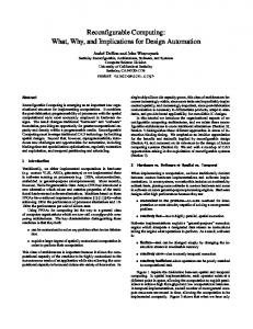
machine learning models like hidden Markov models, neural networks, and newer models such as variable-order Markov models can be considered special cases of Bayesian networks. Figure 1 illustrates a realistic dynamic Bayesian gene network generated from apoptosis timecourse data in [15], where dots represent transcripts (“nodes”) and arrows between the dots represent potential cause and effect interactions between transcripts (“edges”).
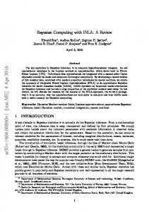
are no undirected cycles. Every directed tree is a polytree, but not every polytree is a directed tree. Figure 2(a) shows a polytree which is not a directed tree. Polytrees often are encountered in Bayesian networks. In fact, some problems can be solved for polytrees in polynomial time but take exponential time in general networks.
(a)
(b)
Figure 2: Two directed graph examples. (a) Polytree and DAG. (b) DAG.
3.
Figure 1: A dynamic Bayesian gene network generated from apoptosis timecourse data. Many practical problems, such as the forward/backward algorithm, the Viterbi algorithm, and the Pearl’s belief propagation algorithm for Bayesian networks, can be translated into an “inference” formulation, which tries to compute the posterior distribution of hidden nodes given observed nodes in a graphical model, in particular the marginal distribution of each hidden node. Typically, a graphical model defines a joint distribution p(x1:N ). Assuming there is no observed node, we can solve a wide range of problems under the Bayesian framework by evaluating the marginal p(xn ) on node n, defined by p(xn ) =
X x1
···
XX xn1 xn+1
···
X
p(x1:N )
xN
Unfortunately, because a typical Bayesian network normally has an exponential number of such terms, even with speed-up techniques such as variable elimination, junction tree, and the sum-product algorithm, we still face prohibitively long evaluation time for any large-scale Bayesian network [11]. Refer to [1] for more detailed discussions on various algorithms. This work aims to develop effective techniques for evaluating large-scale Bayesian networks with high throughput.
2.1 Computing Model At the high level, the computing of Bayesian probabilistic networks can be treated as an evaluation of a set of task nodes constrained by a precedence graph, whereby each Bayesian graph node corresponds to a node in the task graph. In this work, we focus on a class of graphs called polytrees. In graph theory, a polytree [3] or singly connected network is a directed graph with at most one undirected path between any two vertices. In other words, a polytree is a directed acyclic graph (DAG) for which there
BAYESIAN COMPUTING MACHINE
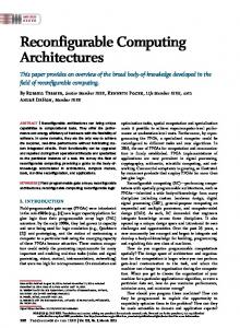
The architecture of our BCM is highly optimized for evaluating Bayesian algorithms. Despite its conceptual similarity to a modern multi-processor system or a many-core processor, our BCM has its unique structure shown in Figure 3. More specifically: • Each processing node only implements the minimum hardware required for the necessary Bayesian computation. More specifically, it receives two input messages, performs the necessary computation, and then sends an outgoing message. The exact computation needed in each processing node depends on the Bayesian algorithm considered and is defined by: – sum-product algorithm: the outgoing message is obtained by taking the product of both incoming messages and multiplying it by the inverse of the sum of all incoming messages received so far at this processing node. – max-sum algorithm: the outgoing message is obtained by taking the maximum of both incoming messages and multiplying it by the inverse of the sum of all incoming messages received so far at this processing node. More details of both algorithms and their derivations can be found in [1]. To increase throughput, each processing node is deeply pipelined. Unlike in conventional parallel processors implemented with ASIC technology, where the pipeline stages seldom exceed 10 due to data dependencies, in the BCM, we pipeline each processing node to 20∼30 in order to maximize the throughput. Furthermore, instead of building sophisticated control circuitry to handle data or instruction hazards, the BCM completely avoids dependencies by pre-processing the computing task graph as discussed in Section 4 and strategically allocating memory for intermediate results during the execution as discussed in Section 5. • The memory of the BCM is physically distributed in order to take advantage of the massively distributed
Processor
Processor
Processor
Processor
After scheduling, each node is assigned two values: t, the starting time of its execution and pi , the index of its assigned processing node.
Switching Crossbar Scheduler
4. Mem
Mem
Mem
Mem
Mem
Mem
Mem
Switching Crossbar
(a) Processor
Scheduler
(b) Figure 3: (a) Major components in a BCM and their interconnection. (b) Diagram of pipeline stages in processing node and memory allocator. memory blocks in a modern FPGA. The communication between processors and memories is handled by two separate crossbar switches as shown in Figure 3. The number of distributed memory modules is at least two times the number of processing nodes, and will be more if each memory module runs slower than the processing nodes as discussed in 5. Combined with preprocessing of the computing task graph in the compilation phase, our novel memory allocation scheme can effectively avoid any data dependency and memory hazards. • As for each processing node, the scheduler that controls the two crossbars is also deeply pipelined to improve the throughput. Given the fact that all information needed for memory allocation of outgoing messages is available before its results, we can start computing the schedule right after the first stage of the processor. This situation is depicted in Figure 3(b).
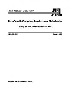
3.1 Code Compilation and Execution A user application is defined as a task graph, where each node represents a unit of computation. The BCM considers a DAG G (directed acyclic graph), which is a directed graph with no directed cycles. Note that a polytree is a strict subset of the DAG. The BCM accepts a DAG with arbitrary topology and size. Each node can have larger-than-2 indegree and larger-than-1 out-degree. To save hardware, each processing node of the BCM only accepts two inputs and one output. Consequently, for a DAG G with arbitrary in-degree and out-degree, we first transform it into a binary DAG G2 by adding intermediate nodes as illustrated in Figure 4(b). For nodes with out-degree larger than 1, we replicate the output result in memory, so downstream nodes can read them without conflict. Let G∗ be the resulted graph, where each node ni has indegree din ≤ 2 and out-degree dout = 1. Each node contains information defined by a 2-tuple {i1 , i2 }, where {i1 } and {i2 } are the indices of its two parents. Together with precedence latency D, G∗ is fed to the schedule detailed in Section 4.
OPTIMALLY SCHEDULING PROCESSORS
As in any parallel computing environment, efficient scheduling of a task graph onto multiple processors is vital for achieving high performance. In this work, we consider the problem of scheduling constant-length jobs on N identical parallel processors to minimize the makespan in the presence of precedence constraints, precedence delays, and communication delays. We assume that each task needs execution on each pipeline stage and that each pipeline stage is unit-length. This work only concerns the precedence constraints that can be described as a DAG. Because the structure of our Bayesian task graph in terms of its task execution times, task dependencies, as well as task communications and synchronization, is known a priori, our scheduling can be accomplished statically at compile time. Although in our BCM, all processing nodes reside on a single FPGA, one can view them as independent processors, and apply the previous research on multi-processor scheduling to this compilation problem. 1
a
b
c
2
a
1
c
b
2 d
h
e
3
g
f
4 5
i
(a)
j
d 3 e
h
5
f
4
6
i
g
j
(b)
Figure 5: Scheduled task graph. (a) D=1. (b) D=2. More concretely, we will consider the problem of scheduling L unit-length tasks on N identical parallel processing nodes to minimize the makespan in the presence of precedence constraints, precedence delays and communication delays. Precedence constraints model dependencies between the tasks; assuming a directed acyclic precedence graph G = (V, E) on the tasks V. With each precedence-constrained task pair (i, j) ∈ E, and pair of processing nodes (a, b), there is an associated non-negative delay di,j,a,b bounded by a constant D. An edge between tasks i and j means that if task j depends on task i, then task j can not be executed until at least di,j,a,b time units after task i finishes. To appreciate the significance of precedence delay, consider the task graph shown in Figure 2 as an example. If all precedence delay di,j,a,b equals to constant 1, the schedule depicted in Figure 5(a) is valid and the make-span is 5. In contrast, if precedence delay increases to 2, the schedule in Figure 5(a) becomes invalid because the separation time between task a and d is not sufficient. On the other hand, the schedule in Figure 5(b) is valid for precedence delay 2. The objective of our static scheduling is to minimize the schedule length and thus the overall execution time. It is well known, however, that multiprocessor scheduling for most precedence-constrained task graphs is an NP-complete problem in its general form [16]. To make this problem feasible, simplifying assumptions are often made regarding the task graph structure representing the program and the
12
13
8
14
9
10
11
7
5
1
4
6
3
12
13
14
8
9
10
11
3
m1
7
5
6
2
(a)
1
Level 4
12
13
Level 3
8
9
14
11
4
Level 2
Level 1
2
(b)
10
m1
7
5
6
1
4
2
3
(c)
Figure 4: (a) A task graph. (b) Converted binary graph with node m1 inserted. (c) A scheduled task graph. model for the parallel processor systems [17]. In this work, we adopt a simple heuristic scheduling algorithm based on Graham’s list-scheduling rule (LSA) [18], which guarantees a 4-approximation ratio to the optimal solution. Note the original scheduling algorithm in [18] applies only to nonpipelined processors, while our algorithm listed as the following is a straightforward extension. To our knowledge, our work is the first study to consider optimal task scheduling for pipelined processors with constant precedence delay.
bandwidth, no two processing nodes can write data into the same memory module during the same clock cycle. Additionally, no more than one processing node can read from a single memory module during the same clock cycle. In the following, we first give the minimum number of memory modules and devise a memory allocation scheme to avoid read or write conflicts. Memory Processor
Algorithm 1 Task Scheduling Algorithm for BCM Given task list {Ti |i = 1, 2, · · · , L} and Ti = 1, 2, · · · , L; Initially every processing node pj , j = 1, 2, · · · , N , is un-occupied, with completion time Γj = 0 for all j = 1, 2, · · · , N . for k = 1 to L do Let task j = Tk . Its starting time is Sj = max(max{Ci + dij |(i, j) ∈ E}, min{Γh |h = 1, · · · , N }) and its completion time is Cj = Sj + pj . Assign job j to a processing node h such that Γh ≤ Sj . Update Γh = Cj . end for Various rules can be used in Step 5 in Algorithm 1 for the choice of the assigned machine h. In this study, we choose the processing node with largest completion time Γh (so as to reduce the idle time between Γh and Sj ). [18] has shown 2 that Algorithm 1 is a (4 − m )-approximation algorithm, i.e., the performance is guaranteed to be no more than 4 times worse than the optimum solution. The output of algorithm 1 is a schedule that assigns each job to a processor at certain time slot.
5. HAZARD-FREE MEMORY ALLOCATION During each time slot, each of the N processing nodes produce a single result, which is written into one of the M memory modules and later read by certain processing nodes. Corresponding to the distributed RAM blocks in modern FPGAs, we assume each memory module has separate write and read ports. In this study, we generalize the memory read and write latency to be r clock cycles—a bounded constant. The impact of memory latency is twofold: first, memory latency (> 1) translates into communication delay between processing nodes, which requires our task scheduling to be intelligent enough to separate job batches far enough to avoid memory stalls. This is discussed in Section 4. Second, because each memory module has limited
1
Memory
Processor 2
Memory
Processor 3
Memory
N
Memory
1 2 3
Processor 1 Processor 2 Processor 3
4
Processor
Processor N
M
(a) Processor
Memory
Processor
Memory Processor
Processor Memory
Processor
Memory
Processor
(b) Figure 6: (a) Diagram of connections between processing nodes and memory blocks. (b) An example of N = 3 and M = 4. Figure 6(a) depicts the interconnects between N processing nodes (processor) and M memory modules and Figure 6(b) illustrates a simple case where N = 3 and M = 4. In both illustrations, the right and left sides of processors only reflect a logic view; there is only one physical copy of all processing nodes. When the results are computed and written to the middle memory modules, each faces two kinds of conflicts. During any particular clock cycle, outgoing data cannot be written to the same memory module. We refer to these as input conflicts. Since there are N processing nodes, the maximum number of arrival conflicts an outgoing result can have is (N −1). Output conflicts occur if multiple results in the same memory memory are accessed simultaneously by different processing nodes. Again because there are N pro-
cessing nodes, the cardinality of this set of conflicts is also (N −1). Thus by the pigeon hole principle, a scheduler needs only M ≥ (2N −1) memories to avoid any memory conflicts. To completely eliminate memory stalls in a BCM, the memory scheduler has to ensure that both input and output conflicts can be resolved during any clock cycle. Input conflicts can be avoided if computed results from all processing nodes can be written to distinct memories. Output conflicts can be avoided if, during any clock cycle, all data items to be consumed by all processing nodes come from different memories. Each output result pt,k from processing nodes can be indexed as a 2-tuple (t, k), where t is the future clock cycle when pt,k will be read out by the processing node nk , i.e., departure time. Both t and k values for each output result from the scheduling of task graph during compilation stage. Note that t and k values encode both topology of Bayesian graph and inter-pipeline stage latency. For memory module j, 1 ≤ j ≤ M , it is available to pt,k if and only if memory module j doesn’t contain any saved result with the same departure time k. For output result pt,k during clock cycle i, we define the set of all available memory modules as available memory set—AM S(pt,k , i). We adopt the following memory allocation scheme:
able to read its intended input data from its corresponding memory module, i.e., there is no output conflict. To prove there is no input conflict, i.e., each processing node, after its completion, can find at least one available memory module to write its output data, we need to show that there always exists a matching that pairs each newly computed output data with a distinct compatible memory. We prove this by induction. Let s be the induction step. 2 Induction Hypothesis: Initially, because all memory modules are empty, our allocation scheme can obviously succeed. Assuming for step s and before, the memory allocation scheme resolves all input and output conflicts. 2 Induction step: During step s + 1, let t be the clock cycle. Because we have N processing nodes, there can be at most N − 1 output results already in the memories having departure time t. Consequently, there are at least M − (N − 1) memories which do not have a output data with departure time t. Because there are M ≥ 2N − 1 memory modules, then at least N memories do not have an output data with departure time t. Additionally, we need to prove the AMSs (available memory sets) for all processing nodes are non-empty. Without loss of generality, consider processing node j. We use the contradiction method for the proof. Suppose the AMS of j is empty, which means all memory modules either contain output results with the same departure time as the output data from processing node j or are allocated for another processing node to write its output data. Since at most N − 1 processing nodes have been assigned to memory modules and at most N − 1 output data will have the same departure time t, the maximum number of unavailable memory modules must be less than 2N −2, which means at least M − (2N − 2) > 0 memory modules are available—a contradiction.
Algorithm 2 Memory Allocation Algorithm for the BCM For each output pt,k result to be written into memory, determine its AM S(pt,k , i), i.e., memories that do not currently store output results with the same departure time. Compute an allocation to memories which pairs each output result pt,k with a distinct available memory within AM S(pt,k , i). Conceptually, the above memory allocation process can be treated as finding a maximum matching for a bipartite graph, which is illustrated by a simple example in Figure 7. The available memory sets for the three processing node (pi , i = 1, 2, 3) are {1, 3}, {1}, and {2, 3, 4}, respectively, which can be converted into a bipartite graph depicted in Figure 7(b). One valid memory allocation can be represented by the matching in Figure 7(c). Processor
AM S
1
{1, 3}
2
{1}
3
{2, 3, 4}
1 1 2 2
3
3 Processor
(a)
1 1
4
2 2
3
3
4
Memory (b)
(c)
Figure 7: (a) Available memory set. (b) Bipartite graph. (3) Maximum matching. We now proceed to prove that the above memory allocation algorithm (Algorithm 2) does yield a valid schedule. If Algorithm 2 can be successfully executed during all clock cycles, because at most one output result in a memory module can have a specific departure time for a given processing node to consume, and only one output result with a specific departure time is ever written to a given memory, it should be clear that during any clock cycle, every processing node is
The above proof not only establishes that Algorithm 2 can always produce a valid memory allocation void of read and write conflicts, but also implies the optimal matching needs not be maximum matching—a maximal matching is sufficient. Since maximum matching has been shown to be expensive to compute even for small size of bipartite graph, this observation is vital to simplify the implementation of our memory allocation scheme.
6. 6.1
HARDWARE PROTOTYPING Processing Node
One challenge of this study is performing floating-point computations with FPGAs. Because FPGA floating-point units are typically clocked 10 times slower than the equivalent in contemporary processors, the BCM architecture has to exploit both the massive parallelism found in FPGAs and the fact that the precision can closely match the application’s requirements in order to achieve the desired throughput [19, 20, 21]. In this work, we adopt a parameterized floating-point unit design capable of only addition and multiplication and choose single precision over double precision, because it consumes a smaller fraction of the FPGA’s resources and has smaller latency. Furthermore, we deeply
pipeline each processing node into 18 stages in order to maximize its throughput. Our implementation of the floatingpoint unit is largely adopted from [19]. Figure 8 shows the flow-graph of an abstract floating-point operator divided into these steps. Signb
Prepare Sign
Expa
Expb
Fraca
Fracb
Operateon Exp
Integer Operator
Adapt Sign
Adapt Exp
Roundand Normalize
Signout
Signout
Expout
Normalization
Prepare Frac
Operation
Prepare Exp
Preparation
Signa
Figure 8: Diagram of the floating-point operator in BCM.
Stored Word 0 Stored Word 1 Stored Word 2 n-bit Address
In this work, we concentrated on achieving the highest possible throughput. Among many techniques, pipelining allows a designer to trade the minimum clock period of a circuit for latency in number of clock cycles. This technique is especially attractive in the BCM, a feed-forward design where no dependencies disrupt the flow of data, allowing an unbounded number of pipeline stages without the need for bypassing or stalls. Additionally, the BCM uses the special memory allocation scheme described in Section 5 to prevent any memory read and write misses. Both these features are in sharp contrast to a general-purpose processor design, where data dependency and conditional branches often cause serious performance degradation in long pipelines. One key aspect of pipeline design is balancing pipeline stages in order to produce the lowest overall combinational delay. Unlike conventional pipeline designs, we automate the pipeline design of the BCM by exploiting sophisticated FPGA tools that optimize pipeline stages by balancing the logic between the registers separating the pipeline stages. Specifically, we start with a bulk design of processing node logic attached to a number of shift registers and then use the Xilinx ISE tool suite to synthesize, place, and route with strict timing constraints. This processing forces our original logic design to be repartitioned and retimed to achieve the best overall throughput. This approach enables a designer to produce reusable functional blocks with a parameterized latency—an approach that increases the longevity and usefulness of the block, and simplifies its integration into latency-constrained systems, such as statically scheduled cores.
to the main memory, a fast look-up is first performed in the CAM structure in order to find any entry with the invalid bit set. The match line address is then used to write the resulted data to an available entry in main memory. Note that each stored word entry in the CAM is directly mapped to an entry in the main memory and therefore, memory addresses are not stored in the CAM. The motivation behind this CAM-based indirect approach is two-fold: 1) since all block RAMs share a common address space, the CAM structure permits balanced use among all processing nodes and accommodates excessive usage by a few processing nodes (this scheme resembles the virtual memory scheme typically found in operating system), and 2) more importantly, the CAM structure provides quick access to the global state of memory allocation, which is crucial to the hazard-free memory allocation scheme discussed in Section 5.
Stored Word 2n − 1 Search Word
Memory Bank
(a)
Input Port
Output Port
Departure Time
(b) Figure 9: (a) Indirect memory addressing by CAM. (b) Data format of each CAM entry. There are various ways to implement the CAM structures inside an FPGA. Our design is based on Virtex-specific device features including fast dedicated carry chains, distributed RAM, built-in shift registers (SRL16E) and Virtex Block SelectRAM + memory. We attempted three implementing methods based on purely logic, LUT RAM, or block RAM. The main advantage of using existing RAM structures in FPGAs is its high density, because by implementing the compare table in distributed RAM, the other logic in the CLB (carry chain, muxes, flip-flops, etc.) is still available to the designer. The other alternative is to use the logic fabric to implement the CAM from scratch, which, although low in density, offers the highest flexibility in pipelining. Results of various implementation are listed in the following table. Config.
Structure Type
Area
Performance-MHz (# of Pipeline Stages)
BRAM32k LUT RAM CLB BRAM32k LUT RAM CLB