frequency, and the high voltage sectioned transformer ... rise voltage to 60 kV after high-voltage breakdown, .... connected 10 meters of high-voltage cable.
Proceedings of RuPAC 2008, Zvenigorod, Russia
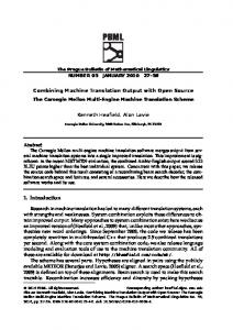
HIGH-VOLTAGE SOURCE WITH OUTPUT VOLTAGE UP TO 60 KV WITH OUTPUT CURRENT UP TO 500MA Gusev I.A., Medvedko A.S., Protopopov A. Yu., Pureskin D.N., Senkov D.V. BINP Novosibirsk Russia Abstract
Overview
The presented report contains the description of highvoltage source with output voltage up to 60kV and output current up to 500 mA. The source consist of the converter with IGBT switches , working with a principle of pulsewidth modulation on programmed from 15 to 25 kHz frequency, and the high voltage sectioned transformer with the rectifier and additional capacitive filter. The transformer is placed in oil tank with silicon oil. The additional capacitive filter provides low ripple and noise level in working range of output currents. The design of the high-voltage transformer provides preservation of working capacity at voltage up to 100kV. The stored in transformer and matching circuit energy is less than 15 J at maximum operating voltage 65kV. The efficiency of system is more than 80% at the nominally output power 30kW. The controller of the source is developed with DSP and PLM, which allows optimizing operations of the source, optimizing short circuit protection and transient process for load variation. Transient process is less than 6kV in voltage and the transient process time is less than 5ms for full load variation from 0 to 500mA. For control of the source serial CAN-interface is used. The description of the source and the test results are presented.
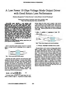
The design of power part high-voltage source is shown in figure 1. The high-voltage source consists of the 20 kHz power converter with insulated gate bipolar transistors (IGBT) as switches (part A) and high-voltage sectioned transformer with the rectifier (part B). The design of power converter consists of 3-phase rectifier D1-D6, electromagnetic (EMI) filter F1, switch SW1, rectifiers filter L1 C1-C4, 20 kHz inverter with IGBT switches Q1-Q4, impedance matching design L2, C5, and isolation transformer T1.
Input rectifier EMI filter is used to eliminate high-frequency noise to the power line from the source. 3-phase rectifier and filter C1-C4 is used to rectifier input AC 3-phase voltage 380V 50Hz to DC 550-600V voltage. Voltage ripple level on capacitors C1-C4 amount less then 1-% with output power 30 kW. Switch SW1 is used for converter soft start. First group of switches is switched on and the filter’s capacitors C1-C4 are charged with 10A current. When the voltage on filter is up to 450 volt level the second group of switches is switched on and the rectifier is connected directly to 3-phase AC line.
DESCRIPTION
Inverter
The presented source was designed for some different Budker institute of nuclear physics internal applications. That was reason for some specific terms like: fast time for rise voltage to 60 kV after high-voltage breakdown, strong reliability to high-voltage breakdown, breakdown energy less than 15 J for 60 kV operation, low voltage ripple for maximal power operation. The basic characteristics of high-voltage source are shown in table1. Table 1 : Basic parameters of high-voltage source. Parameter
Full-bridge inverter Q1-Q4 converts DC 550V voltage to AC voltage with 20 kHz frequency. Inverter working with principle of pulse-width modulation (PWM) with 2 circles: freewheeling when switches Q2, Q4 are switched on (ON) and energy addition when Q1, Q4 or Q2, Q3 are ON. With this conditions the IGBT switches is been in soft switching mode, and the switching transient process and the switching energy loss are minimised.
Matching circuit
Unit Min
Nom
Max
Output voltage
kV
10
60
70
Output current
mA
0.1
500
550
Output power
kW
Voltage ripple
%
0.5
Voltage stability
%
0.2
Current Modulation
From 1 mA to 500 mA
Transient time
ms
5
Inverter frequency
kHz
20
The power source must work with wide range of loads, from zero current to full load. The technical conditions for this high-voltage source are: transient process time must be less then 5 ms with transient voltage jump less than 6kV for 60 kV operations for load switching between 20mA and 250mA (full load). The matching circuit consists of C5, L2, L3 is used for minimising transient process and for improving efficiently of design. Magnetising inductance, parallel parasitic capacitance and the matching circuit organise low-pass filter for all high harmonics of inverters rectangular alternating voltage. That way, sinusoidal voltage is feed in the high-voltage transformer, because all high harmonics are filtered. In other case, the presence of high harmonics causes power dissipation in the leads because of scin-effect. Also this harmonics can induce the singing in the winding of highvoltage transformer.
30
07 Power Supplies, Magnetic And Vacuum Systems
168
Proceedings of RuPAC 2008, Zvenigorod, Russia
L1
T2
High-voltage transformer AC 150V
Q1 VD1 F1
VD3
VD5
C1
Q3
C3
-60kV
SW1 Csc C5
A
L2
Cf
T1
Rm 150M
Ro 15M
B Csc
Cf
Rm 150M
Ro 15M
Csc
Cf
Rm 150M
Ro 15M
Csc
Cf
Rm 150M
Ro 15M
C TRANSFORMER VD2
VD4
VD6
C1
C4
Q2
PART A
Q4
20 KHZ POWER CONVERTER
PART B
HIGH-VOLTAGE Rsh VOLUME 40+400 Om
DSP CONTROL CURCUIT T
R1 TERMISTOR
TEMPERATURE OUTPUT CURRENT OUTRUT VOLTAGE
Figure 2. The gain frequency characteristic of matching circuit with the high-voltage transformer channels with 12bits precision. These channels are shown in table 2. The controller has CAN-bus interface which is used to link with a controlling system. The used data rates is 125, 250 and 500 Kbits in second. The protocol of CAN-bus interface is compatible with devises produced in the Budker institute of nuclear physics [2].
High-voltage transformer Sectioned high-voltage transformer consists of four step-up high voltage sections. Each section is complete design and it includes winding, half-bridge rectifier and output filter capacitors. Output voltage for section is 15 kV for 60 kV operations. Output filter includes the filters Csc in sections and addition high voltage output capacitor Cf. Output filter capacity is chosen for output voltage 40 kHz ripples less than 0,5% for full load operation. The top section of high-voltage transformer has addition winding with 150 volts AC 200 watts power output for supply of high side control circuits and the cathode heat. For improve transient process after switch current from 500mA to 0 mA the addition load Ro is added. The transformer is designed in oil-filled tank (diameter 600mm, high 800mm). The silicon oil [1] is used.
Protections and interlocks Breakdown protection controls output current. If this current up to 600 mA or higher the converter switches off (OFF). If output current is higher then digital setup level (from 5 to 500 mA) the converter switches off (OFF). Switching off time is less then 50 microseconds. For that reason, the breakdown energy less than 15J for 60 kV operations with connected 10 meters of high-voltage cable. The converter trays to switch on after 10 milliseconds with rise speed 1kV/msec. If the breakdown protection switches off the converter again rise speed is decreased to 100V/msec. High-voltage transformer protection measures the temperature of transformer and input current. If the input current of transformer rise up to 200A that matter the short circuit in transformer. In this case the converter is OFF.
Design The converter is made in tree Schroff 6U cases in the rack. There are distilled water is used to cool IGBT switches and other elements. There are EMI-filter, input switch and rectifier constructed in the first crate. There is filter capacitors, inverter and control circuit located in the second crate. And at last, there are capacitor and inductors of matching circuit located in the third crate.
RESULTS The high-voltage source was made and has being test with the electron beam gun for year. The power supply is tested with breakdown rate 1-2 breakdown in minute for output voltage 60kV within 3 hours. The tests are shown high reliability, efficiency better than 85% for full load operations. The long time stability of output voltage was better than 0,2%. Voltage ripple was better than 0,5%. Continues work in full load operations is 8 hours and longer.
Control circuit The control circuit is realised in digital signal processor (DSP), programming logic matrix array (PLM), and analogy input buffers. The control and analogue grounds are isolated from external signals and grounds and, that way, in control circuit has obtained low noise level. Its allow operate with better then 0.1% measures precision. All the IGBT switches are protected from short circuit and overcurrent. The controller measured 7 analogue 07 Power Supplies, Magnetic And Vacuum Systems
169
Proceedings of RuPAC 2008, Zvenigorod, Russia
Table2. Measured channels Channel
period
diapason
Output voltage Output current Input current highvoltage transformer Feedback signal Input 3-phase voltage (r.m.s.) Input current (r.m.s.) Temperature of IGBT switches Temperature of high-voltage transformer
50μsec 50μsec
0-60.00kV 0-300.0mA
50μsec
0-200A
25μsec
0-3000mV
1msec
0-600V
1msec
0-100A
1sec
0-70°C
1sec
0-100°C
[3]
REFERENCES [1] http://www.sofex.ru/pdf/SOFEXIL-TCJ.pdf. Transformer fluid technical manual. [2] V. R. Kozak, M. M. Romakch “The devices vith CANBUS interface for automatic control systems of physical complexes” pre-print BINP 2004-68, 2004
07 Power Supplies, Magnetic And Vacuum Systems
170
I.A.Gusev, A.S.Medvedko, A.Yu.Protopopov, D.N.Pureskin, D.V.Senkov, Yu.F.Tokarev, V.D.Yudin “High-voltage source with output voltage up to 60 kV with power up to 15 kW” , Proceedings of RuPAC 2006, Novosibirsk, Russia, 2006 P.82.