simply timing SDS addition, to give linearly aggregated cores of 2â20 particles. The in situ formation of conductive polymer shells has allowed the isolation and ...
View Article Online / Journal Homepage / Table of Contents for this issue
Published on 30 March 2009. Downloaded by Fujian Institute of Research on the Structure of Matter, CAS on 15/07/2013 04:32:44.
PAPER
www.rsc.org/materials | Journal of Materials Chemistry
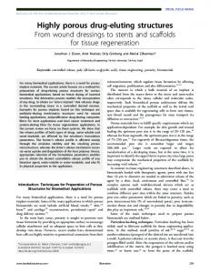
Highly controlled core/shell structures: tunable conductive polymer shells on gold nanoparticles and nanochains† Shuangxi Xing,a Li Huey Tan,a Miaoxin Yang,a Ming Pan,a Yunbo Lv,a Qinghu Tang,b Yanhui Yangb and Hongyu Chen*a Received 16th January 2009, Accepted 5th March 2009 First published as an Advance Article on the web 30th March 2009 DOI: 10.1039/b900993k Controls in coating gold nanoparticles with conductive polymers are reported, where uniform core/ shell nanoparticles with tailored core aggregation and shell thickness are unambiguously demonstrated. In the presence of sodium dodecylsulfate (SDS), the adsorption and in situ polymerization of aniline or pyrrole on the surface of gold nanoparticles gives uniform polymer shells. A typical single encapsulation of 10 nm gold nanoparticles gave �99.1% monomers out of 1074 particles surveyed. The shell growth was found to be kinetically controlled; polyaniline was successively grown on 22 nm gold nanoparticles by multiple growth cycles, giving shell thicknesses of 14, 31, 61 and 92 nm, respectively. We show that the aggregation of gold nanoparticles can be controllably promoted in this system, by simply timing SDS addition, to give linearly aggregated cores of 2–20 particles. The in situ formation of conductive polymer shells has allowed the isolation and unambiguous characterization of these nanochains for the first time. The one-step, ‘‘mix-and-wait’’ synthesis solely utilizes inexpensive starting materials and is, therefore, well-suited for fabrication of large quantities of core/shell nanoparticles. The core/shell nanoparticles form stable colloidal suspensions and can be readily purified by centrifugation.
Introduction Controlling the composition, morphology and structural order of nanoparticles (NPs) is of paramount significance in tailoring the properties of nanomaterials. Over the past decade, core/shell structure has attracted much attention as the extra dimension of control over NPs.1,2 For optimal control of the properties, an ideal sample of core/shell NPs should form a stable, non-aggregated suspension, with uniform shells that each completely covers a single core (Scheme 1a). The major synthetic challenge, therefore, is to prevent the uncontrolled aggregation before and after the encapsulation process, as the former leads to multipleinclusion of NPs in the shells and the latter leads to non-colloidal precipitates (Scheme 1b and c). A variety of synthetic methods for core/shell NPs have been reported. Core/shell NPs of inorganic materials have been wellstudied, although highly controlled conditions and sensitive protocols are often necessary to minimize aggregation. Methods such as surface nucleation and reaction have prepared near-ideal core/shell NPs (hereafter abbreviated as core@shell), e.g. Au@Ag,3 Fe2O3@Au, Au@TiO2, Au@Fe3O4, Au@SiO2, FePt@SiO2, Co@CoO, Fe@Fe3O4, etc.2 In comparison, coating polymers on NPs has been less successful, as it is often more a Division of Chemistry and Biological Chemistry, Nanyang Technological University, 21 Nanyang Link, Singapore 637371. E-mail: hongyuchen@ ntu.edu.sg; Fax: (+65) 67911961; Tel: (+65) 6316 8795 b Division of Chemical and Biomolecular Engineering, Nanyang Technological University, 62 Nanyang Drive, Singapore 637459 † Electronic supplementary information (ESI) available: Large-area TEM images, UV-vis spectra of AuNP-chains before and after encapsulation, and Raman spectrum of AuNP@PPy (Fig. S1–S12). See DOI: 10.1039/b900993k
3286 | J. Mater. Chem., 2009, 19, 3286–3291
difficult to control aggregation, particularly for small NPs ( 18 MU cm�1).
observable precipitate. To isolate AuNP@PANI, the reaction mixture (2 mL) was centrifuged at 14 000 rpm for 15 min, the supernatant was removed and the concentrated NP solution was collected at the bottom of the Eppendorf tubes. The NPs, which were redispersed in SDS solution (3.6 mM, 2 mL), were mostly free of excess PANI and other reactants. The solution was stable for months and can be further purified by centrifugation. Further polymer growth cycles were carried out using the isolated AuNP@PANI, following the mixing sequence above to obtain a final solution of 3.3 mL, where [aniline] ¼ 0.9 mM, [SDS] ¼ 3.6 mM, [(NH4)2S2O8] ¼ 0.9 mM and [HCl] ¼ 4.5 mM. As-synthesized AuNRs20 (3 mL) were purified by first centrifuging at 14 000 rpm for 15 min and then dispersing the concentrated AuNRs in water. This purification was repeated once more to further remove the excess CTAB. After these purification steps, the AuNRs were encapsulated by PANI using the standard method. Synthesis of core/shell NP@PPy The process is similar to that of the AuNP@PANI, except that pyrrole was used instead of aniline. The reactants were mixed in the order given above, to obtain a mixture of 3.3 mL, where [pyrrole] ¼ 0.9 mM, [SDS] ¼ 3.6 mM, [(NH4)2S2O8] ¼ 0.9 mM and [HCl] ¼ 4.5 mM. The reaction mixture was incubated at room temperature for 48 h (not optimized) to ensure complete polymerization. As-synthesized PtNPs21 solutions (0.2 mL) were added acetone (1.3 mL) and the mixture was centrifuged at 8000 rpm (5200 g) for 8 min. The concentrated PtNPs were dispersed in a mixture of ethanol and hexane (vol 1 : 3), centrifuged at 8000 rpm for 8 min and then treated with a further centrifugation–resuspension cycle at 14 000 rpm for 15 min. After these purification steps, the PtNPs were encapsulated by PPy using the standard method. Linear aggregation of AuNPs followed by PANI Encapsulation As-synthesized citrate–AuNPs solutions (24 mL) were concentrated to a total of 112 mL, by centrifugation at 14 000 rpm for 15 min. The isolated AuNP solution was then added to an aqueous aniline solution (2 mM, 24 mL). At specific time intervals, 3 mL of the reaction mixture was extracted, and equally divided into two tubes. Then, SDS solutions (40 mM, 300 mL) were added to each of the tubes to terminate the AuNP aggregation. One set of tubes was used for the growth of PANI shells and the other set was used as a control for stability tests.
Synthesis of core/shell NP@PANI Citrate-stabilized AuNP (citrate–AuNPs) solutions (4.5 mL) were concentrated to a total of 18 mL by centrifugation at 14 000 rpm (16 000 g) for 15 min. After removal of supernatant, the isolated NPs were added to a mixture of aniline (2 mM, 1.5 mL) and SDS (40 mM, 300 mL). Then the solution was vortexed for 5 s followed by addition of acidic (NH4)2S2O8 solution (2 mM in 10 mM HCl, 1.5 mL). The total volume of the final mixture was 3.3 mL, where [aniline] ¼ 0.9 mM, [SDS] ¼ 3.6 mM, [(NH4)2S2O8] ¼ 0.9 mM and [HCl] ¼ 4.5 mM. After vortexing for 10 s, the reaction mixture was incubated at room temperature for 4–24 h to ensure complete polymerization. The resulting colloidal solution was stable for at least one month without any This journal is ª The Royal Society of Chemistry 2009
Etching of core/shell AuNPs@PANI A NaCN solution (40 mM, 8 mL) was added to a solution of isolated AuNPs@PANI (20 mL) and the mixture was incubated overnight. Charaterization Transmission electron microscopy (TEM) images were collected on a JEM-1400 (JEOL) operated at 100–120 kV. Scanning electron microscopy (SEM) images were collected on a field-emission JSM-6700F (JEOL) operated at 10 kV. Raman spectra were collected from sample solutions in a cuvette (pathlength ¼ 1.00 cm) J. Mater. Chem., 2009, 19, 3286–3291 | 3287
Published on 30 March 2009. Downloaded by Fujian Institute of Research on the Structure of Matter, CAS on 15/07/2013 04:32:44.
View Article Online
on an R-3000HR spectrometer (Raman Systems Inc.) using a red LED laser (l ¼ 785 nm). Ultraviolet-visible (UV-vis) spectra were collected on a Cary 100 spectrophotometer. Preparation of TEM samples (NH4)6Mo7O24 was used as the negative stain in all TEM images reported in this paper unless specifically mentioned, so that empty micelles and polymer shells appear white against the stained background. TEM grids were treated with oxygen plasma in a Harrick plasma cleaner/sterilizer for 1 min to improve the surface hydrophilicity. A sample solution was carefully mixed with stain solution on the surface of a plastic Petri dish ([(NH4)6Mo7O24] ¼ 6.8 mM); the hydrophilic face of the TEM grid was then placed in contact with the sample solution. A filter paper was used to wick off the excess solution on the TEM grid, which was then dried in air for 5 min. The TEM images reported in this work appear quite different compared to those reported in the literature, where conductive polymer shells often appear light grey and, therefore, hardly stand out against the background. The contrast between the shell and background is expected to be the worst if surface polymer chains partially dissolve in the solvent and form a continuous density gradient when a specimen was dried on a TEM grid. In most of our TEM images, negative stain was used to improve contrast. In addition to darkening the background, the stain solution also has significant ionic strength that could reduce the solubility of the polymer chains and thus further improve contrast. The stain concentration would be highest when a sample is nearly dried on a surface. It is also possible that the contrast may depend on the polymer length. As PANI or PPy grow in length they become more hydrophobic,22 thereby improving the contrast against background. This effect can be qualitatively seen in Fig. 3c–f. Preparation of SEM samples A piece of silicon wafer was cleaned thoroughly by water and ethanol and then treated with aqueous 3-aminopropyltriethoxysilane (0.1 wt%) for 15 min. After washing, the wafer was immersed in a purified AuNP@PANI solution for 30 min, washed with water and dried under a nitrogen flow. Presumably, the NH2-coated surface carries positive charges and traps the negatively charged AuNP@PANI.
Results and discussion As shown in Scheme 1d, the single encapsulation of AuNPs by PANI can be simply achieved by mixing aqueous aniline, SDS, citrate–AuNPs, and acidic (NH4)2S2O8 solution ([HCl] ¼ 10 mM) in sequence, followed by incubation for 4 h. The UV-vis spectrum of the resulting solution (Fig. 1c) shows absorption peaks at 360, 430 and 770 nm, indicating the formation of PANI.23 The resulting AuNP@PANI were readily isolated from the excess reactants by centrifugation, and were resuspended in SDS solution. Fig. 1a and b present the TEM images of AuNP@PANI before and after purification. All observed AuNPs (dav ¼ 22 nm) were completely covered by polymer shells of �14 nm thick, which appear white against the stained background. There is no obvious aggregation or fusing of 3288 | J. Mater. Chem., 2009, 19, 3286–3291
Fig. 1 (a) TEM images of AuNP@PANI before and (b) after purification; (c) UV-vis spectra of AuNP@PANI before (curve 1) and after purification (curve 2: supernatant; curve 3: isolated NPs redispersed in aqueous SDS solution (3.6 mM) of same volume as that of the original solution); (d) Raman spectrum of the isolated AuNP@PANI redispersed in SDS solution. Scale bars: 200 nm.
AuNP@PANI as result of the purification. Typical SEM images of the AuNP@PANI trapped by NH2-coated surface also confirmed the non-aggregated state of the singly encapsulated NPs (Fig. S1 in the ESI†). The surface plasmon absorption of AuNP@PANI shifts to ca. 530 nm (Fig. 1c) from the original 520 nm of citrate–AuNPs, suggesting changes in the refractive index of the media near the AuNP surface. Strong PANI absorption peaks were found in the supernatant after the centrifugation but were barely observable in the resuspended AuNP@PANI solution (Fig. 1c), suggesting that the large excess of aniline has polymerized but not all were attached to AuNPs. Apparently, SDS was in sufficient quantity to stabilize the excess PANI, preventing it from coagulating with the AuNP@PANI. This is consistent with the observation of empty polymer spheres of � 8 nm in Fig. 1a. Raman spectrum of the purified AuNP@PANI is given in Fig. 1d. The characteristic peaks at 1588, 1500, 1350 and 1170 cm�1 confirm the formation of PANI close to AuNP surface.24 While seeded polymerization on NP surface has been wellstudied,25 the control of NP aggregation in this process is the key to achieve single encapsulation. In our case, the presence of SDS is crucial for stabilizing AuNPs, both before and after the polymer shell formation. In the absence of SDS, incubation of citrate–AuNPs with aqueous aniline (2 mM) caused the plasmon absorption peak at 530 nm (0 h after mixing) to decrease, while a new absorption peak emerged and slowly shifted from 600 to 700 nm in �10 h (Fig. 2a). These new peaks can be assigned to the longitudinal plasmon absorption bands of linear AuNP aggregates.26 Addition of SDS (3.6 mM) to the mixture almost completely stops the aggregation; the plasmon bands barely shifted even after 12 days of incubation (Fig. S2†). Therefore, it is likely that SDS co-adsorbs with aniline on the AuNP surface (Scheme 1) and introduces net negative charges that prevent further aggregation. Polymerization of aniline at these stages serves as a perfect means This journal is ª The Royal Society of Chemistry 2009
Published on 30 March 2009. Downloaded by Fujian Institute of Research on the Structure of Matter, CAS on 15/07/2013 04:32:44.
View Article Online
Fig. 2 (a) UV-vis spectra of AuNPs incubated in aniline solution, with SDS addition occurred at 0, 2, 4, 5, 6, 7, 8 and 10 h, respectively. The first two spectra overlap with each other. (b–d) TEM images of the AuNPs@PANI by polymerizing the solutions shown in panel (a): (b) 5 h; (c) 7 h and (d) 10 h. Histograms of the nanochains (in number of AuNPs) are shown in the insets. Scale bars: 200 nm.
to preserve the solution species for characterization and application. A series of experiments was carried out that varied the incubation time of AuNPs with aniline, before the addition of SDS to stop aggregation and (NH4)2S2O8 to initiate polymerization. The TEM images showed increasing length of linear AuNP-chains (Fig. 2b–d), corresponding well with the plasmon absorption changes of the UV-vis spectra. The nanochains were all coated with a uniform layer of PANI. Remarkably, they were all single chains with few branches, in contrast to those reported in the literature.26,27 Much of this improvement could be attributed to the presence of polymer shells, which prevented the disordered aggregation that would otherwise occur as a sample dried on a TEM grid. The bottom-up assembly of AuNPs into one-dimensional aggregates has received much attention in recent years owing to its promising applications in various fields.26,28–30 However, in most reports the correlation between UV-vis and TEM characterization cannot be unambiguously established, due to the aggregation of solution species during SEM/TEM sample preparation. In our system, PANI encapsulation has conveniently solved this problem by trapping the aggregates while they are still in the solution phase. Most importantly, the stable polymer shell allows isolation, storage and application of the linear aggregates, which were previously unachievable given the instability of the unprotected nanochains. The less-branched nanochains are also advantageous for future applications. Control experiments polymerizing aniline–AuNPs in the absence of SDS led to aggregation of the nanocomposite as insoluble precipitate. It follows that the steric/charge effects of PANI alone are insufficient to stabilize the NPs. In the presence of SDS, the AuNP surface was constantly stabilized by its negative charge, forcing the seeded polymerization of aniline to localize on the individual NP surface (as opposed to interparticle polymerization). On the other hand, repeated isolation and resuspension of AuNP@PANI in SDS solution (3.6 mM) did This journal is ª The Royal Society of Chemistry 2009
not destabilize the NPs for at least 4 cycles. In contrast, control experiments that used water for the resuspension gave large aggregates within the second purification cycle (estimated residual [SDS] of 0.04–0.07 mM, Fig. S3†). Apparently, the reduction of SDS concentration has led to its dissociation from AuNP surface, which destabilized the NPs. Based on these observations, we conclude that the adsorption and desorption of SDS on the polymer layer are dynamic processes and that the presence of SDS is instrumental for the colloidal stability of AuNP@PANI. Temporal evolution of the polymer shell was studied in the case of single encapsulation, by extracting aliquots of reaction mixture which were then immediately dried on TEM grids. Fig. 3a shows the gradual increase of polymer shell on 22 nm AuNPs over time, from �2 nm at 30 min to �14 nm after 4 h. The shell thickness reaches a plateau after that; no obvious changes could be discerned from 4 to 50 h (Fig. S4†). Meanwhile, the PANI absorption peak at 800 nm roughly follows the same trend; it initially increases but reaches its maximum at �4 h, indicating the end of polymerization (Fig. 3a). The fact that the excess PANI (as empty polymer spheres) did not contribute to shell growth after the depletion of aniline indicates minimal coagulation or net exchange between AuNP@PANI and the PANI spheres. The strong correlation between the two curves suggests that the termination of shell growth was due to aniline depletion, although it cannot be ruled out that the shell growth may be thermodynamically controlled, i.e., the coagulation/ exchange may have ceased because any further increase of shell thickness would destabilize the core/shell NPs. In order to test this ambiguity, the AuNP@PANI were isolated and used in place of citrate–AuNPs for further growth cycles, under otherwise
Fig. 3 (a) Temporal evolution of AuNP@PANI shell thickness (-) and of absorption intensity at 800 nm in UV-vis spectra (B) during the polymerization process; (b) Shell thickness of AuNP@PANI as a function of growth cycles; (c–f) TEM images of AuNP@PANI after the 1st, 2nd, 3rd and 4th growth cycle, respectively. See the ESI for large-size TEM images.† Scale bars: 100 nm.
J. Mater. Chem., 2009, 19, 3286–3291 | 3289
Published on 30 March 2009. Downloaded by Fujian Institute of Research on the Structure of Matter, CAS on 15/07/2013 04:32:44.
View Article Online
identical conditions. The thickness of the polymer shells increased significantly, from the initial 14 nm to 31 nm (Fig. 3c and d). After the 3rd and 4th growth cycle, the shell further increased to 61 and 92 nm, respectively (Fig. 3e and f). The fact that multiple PANI layers could be grown on isolated AuNP@PANI without causing aggregation further substantiates the extraordinary stability of AuNP@PANI during the repeated centrifugation (vide supra). More importantly, this result also demonstrates that the shell growth was kinetically controlled. The uniform shell thickness on AuNP (e.g. Fig. 1a) is more likely due to similar growth rates, and not to the thermodynamic stability of the SDS-stabilized AuNP@PANI. It can also be concluded that dynamic exchange of polymer between AuNP@PANI and PANI spheres is unlikely, as this process would have led to continued shell growth (to minimize surface potential) after the depletion of aniline. Therefore, the growth of PANI sphere and AuNP@PANI during the polymerization (0 < t < 4 h in Fig. 3a) were probably largely independent. The in situ polymerization of aniline on the surface of AuNP is thus a key process for the shell growth. Control experiments that simply mixed citrate–AuNPs with pre-formed PANI in SDS did not give core/shell NPs (Fig. S6†), further supporting this argument. The kinetically controlled shell growth in this system is in clear contrast with the thermodynamically controlled31 encapsulation of AuNPs by diblock copolymers such as polystyrene-blockpoly(acrylic acid) (PSPAA),7,28 where the shell thickness was only slightly variable. The polymer shells of AuNP@PSPAA7,30 were generally more spherical and uniform compared to those of AuNP@PANI (Fig. 1 and 3), consistent with the drastic difference in the growth mechanisms. Nevertheless, the encapsulation by PANI is advantageous in that the shell thickness could be continuously tailored, up to extraordinary proportions with respect to the core size. The encapsulation method reported here is not only facile and scalable, but also economical in that inexpensive SDS was sufficient to control aggregation as well as shell growth. Importantly, conductive polymers such as PANI cannot be easily incorporated into the synthesis of block copolymers, or easily adapted for most other encapsulation methods. Moreover, our preliminary results have shown that the encapsulation method is quite general as it is applicable to a variety of NPs and can even be extended to coat PPy shells. AuNPs of various diameters from 10 to 60 nm have been encapsulated by PANI, with minimal aggregation (Fig. 4a and S8†). While control of aggregation is decent for micron-size NPs as reported in the literature,13,32 it is often more difficult to prevent aggregation of small AuNPs (d < 20 nm). In our system, single encapsulation of 10 nm AuNPs was easily achieved by the one-pot synthesis (Fig. 4a); a typical sample contained 99.1% monomers out of 1074 particles surveyed. Using this method, gold nanorods (AuNRs) prepared by CTAB-capped seed growth20 were successfully encapsulated (Fig. 4b), provided that the excess CTAB was completely removed. Most interestingly, this method also works for PPy encapsulation; adsorption and polymerization of pyrrole on AuNP gave uniform PPy shells. Fig. 4c shows the TEM image of 22 nm AuNP@PPy. The shell thickness (� 11 nm) is close to that of AuNP@PANI and the Raman spectrum confirms the formation of PPy near AuNP surface (1591, 1363, 1245 and 936 cm�1, Fig. S12†).33 In addition, PtNPs prepared by polyol 3290 | J. Mater. Chem., 2009, 19, 3286–3291
Fig. 4 TEM images of (a) 10 nm AuNP@PANI; (b) AuNR@PANI; (c) 22 nm AuNP@PPy; (d) PtNP@PPy. Scale bars: 100 nm. See large-views in the ESI.†
synthesis21 could also be encapsulated by PPy, after the removal of excess poly(vinylpyrrolidone) from the as-synthesized solution (Fig. 4d). The AuNPs in the core/shell structures can be easily etched by NaCN in the presence of oxygen, and hollow nanostructures of conductive polymers were thus obtained. Fig. 5 shows typical TEM images of the resulting PANI nanocapsules and nanochannels. The diameter of the cavities measures �18 nm, slightly smaller than that of the original 22 nm AuNPs. Nevertheless, the cavities roughly maintain the original shape of the cores; it is most obvious in the case of nanochannels (Fig. 5b–d) that resulted from the PANI-coated nanochains (Fig. 2b–d). Of particular interest to us are the hollow PANI nanofibers with variable length and internal structures. These nanochannels with periodic cavities and restrictions are clearly different from the
Fig. 5 TEM images of PANI nanocapsules and nanochannels after etching the corresponding sample shown in Fig. 1b (a), 2b (b), 2c (c) and 2d (d) by NaCN. Scale bars: 100 nm. No stain was used.
This journal is ª The Royal Society of Chemistry 2009
Published on 30 March 2009. Downloaded by Fujian Institute of Research on the Structure of Matter, CAS on 15/07/2013 04:32:44.
View Article Online
hollow tubes reported earlier34 and could be envisioned as selective channels for nanodevices, for an example. To the best of our knowledge, such structures have never been reported before. Considering all the results obtained, we proposed the following mechanisms to elucidate the controls in this system. Adsorption or coordination of neutral aniline molecules on AuNPs replaces the citrate ions, partially neutralizing the negative charges and rendering the surface more hydrophobic. As a result, the AuNPs start to aggregate but the residual surface charges still force the AuNPs to organize linearly.26 Upon introduction, SDS embeds its hydrophobic tail in the aniline layer, while the negative sulfate group stabilizes the NPs against aggregation. On the other hand, if SDS is added before citrate– AuNPs, only singly encapsulated AuNP@PANI are obtained. When polymerization is initiated by (NH4)2S2O8, the surface aniline grows into longer PANI, which renders AuNP surface even more hydrophobic. Monomers or short oligomers would continue to adsorb onto the surface and polymerize, until the monomer is depleted. Apparently, polymerization of aniline also occurs in solution but the resulting PANI is stabilized by excess SDS and cannot further contribute to the shell growth. The adsorption and desorption of SDS on AuNP@PANI were shown to be dynamic, as removal of SDS results in NP aggregation. Nevertheless, the SDS-stabilized AuNP@PANI are stable for months and can even withstand repeated centrifugation, provided that excess SDS is present. The shell growth is kinetically controlled, because multiple layers of PANI could be grown on AuNPs, by simply subjecting the isolated AuNP@PANI to further growth cycles. Therefore, the uniform shell thickness of AuNP@PANI is likely a result of similar growth rates for individual NPs.
Conclusions A facile method was developed to uniformly encapsulate gold nanoparticles by conductive polymers, where structural controls of the core/shell nanoparticles were demonstrated. Linear AuNP chains of variable length were encapsulated by a conductive polymer shell, allowing them to be isolated for the first time. While the facile, scalable and economical fabrication of the core/ shell nanoparticles reduces the cost for future applications, the control over linear core aggregation and polymer shell thickness will allow more intelligent design of their structure and properties.
Acknowledgements The authors thank Division of Physics and Applied Physics for SEM usage and MOE (ARC 27/07) for financial support.
References 1 E. Bourgeat-Lami, J. Nanosci. Nanotechnol., 2002, 2, 1. 2 F. Caruso, Adv. Mater., 2001, 13, 11; M. Casavola, R. Buonsanti, G. Caputo and P. D. Cozzoli, Eur. J. Inorg. Chem., 2008, 2008, 837. 3 C. Xue, J. E. Millstone, S. Li and C. A. Mirkin, Angew. Chem., Int. Ed., 2007, 46, 8436. 4 F. Caruso, Chem. Eur. J., 2000, 6, 413; G. Schneider and G. Decher, Nano Lett., 2004, 4, 1833. 5 D. Li, Y. Cui, K. Wang, Q. He, X. Yan and J. Li, Adv. Funct. Mater., 2007, 17, 3134; T. von Werne and T. E. Patten, J. Am. Chem. Soc., 1999, 121, 7409; T. von Werne and T. E. Patten, J. Am. Chem. Soc., 2001, 123, 7497.
This journal is ª The Royal Society of Chemistry 2009
6 K. Yoshinaga, K. Kondo and A. Kondo, Colloid Polym. Sci., 1997, 275, 220. 7 H. Chen, S. Abraham, J. Mendenhall, S. C. Delamarre, K. Smith, I. Kim and C. A. Batt, ChemPhysChem, 2008, 9, 388; M. Yang, T. Chen, W. S. Lau, Y. Wang, Q. Tang, Y. Yang and H. Chen, Small, 2009, 5, 198. 8 Y. Kang, K. J. Erickson and T. A. Taton, J. Am. Chem. Soc., 2005, 127, 13800; Y. Kang and T. A. Taton, Angew. Chem., Int. Ed., 2005, 44, 409; Y. Kang and T. A. Taton, Macromolecules, 2005, 38, 6115. 9 R. J. Tseng, J. Huang, J. Ouyang, R. B. Kaner and Y. Yang, Nano € Lett., 2005, 5, 1077; D. Wei, J. K. Baral, R. Osterbacka and A. Ivaska, J. Mater. Chem., 2008, 18, 1853. 10 E. Granot, E. Katz, B. Basnar and I. Willner, Chem. Mater., 2005, 17, 4600; L. Yunze, H. Kun, Y. Junhua, H. Dongxue, N. Li, C. Zhaojia, G. Changzhi, J. Aizi and D. Jean Luc, Appl. Phys. Lett., 2006, 88, 162113. 11 D. Y. Godovski, Adv. Polym. Sci., 1995, 119, 79. 12 X. Feng, H. Huang, Q. Ye, J. J. Zhu and W. Hou, J. Phys. Chem. C, 2007, 111, 8463; S. Fujii, A. Aichi, K. Akamatsu, H. Nawafune and Y. Nakamura, J. Mater. Chem., 2007, 17, 3777; Z. Peng, L. Guo, Z. Zhang, B. Tesche, T. Wilke, D. Ogermann, S. Hu and K. Kleinermanns, Langmuir, 2006, 22, 10915; P. R. Sajanlal, T. S. Sreeprasad, A. S. Nair and T. Pradeep, Langmuir, 2008, 24, 4607. 13 Z. Wang, J. Yuan, D. Han, L. Niu and A. Ivaska, Nanotechnology, 2007, 18, 115610. 14 T. Selvan, J. P. Spatz, H.-A. Klok and M. M€ oller, Adv. Mater., 1998, 10, 132. 15 D. Mu~ noz-Rojas, J. Or� o-Sol�e, O. Ayyad and P. G� omez-Romero, Small, 2008, 4, 1301. 16 S. M. Marinakos, J. P. Novak, L. C. Brousseau, A. B. House, E. M. Edeki, J. C. Feldhaus and D. L. Feldheim, J. Am. Chem. Soc., 1999, 121, 8518; S. M. Marinakos, D. A. Shultz and D. L. Feldheim, Adv. Mater., 1999, 11, 34. 17 Y. Dong, Y. Ma, T. Zhai, Y. Zeng, H. Fu and J. Yao, Nanotechnology, 2007, 18, 455603. 18 L.-Y. Chu, S.-H. Park, T. Yamaguchi and S.-i. Nakao, Langmuir, 2002, 18, 1856; M. Ocana, M. Andres-Verges, R. Pozas and C. J. Serna, J. Colloid Interface Sci., 2006, 294, 355; Y. G. Han, T. Kusunose and T. Sekino, Chem. Lett., 2008, 37, 858; S. Xing, L. H. Tan, T. Chen, Y. Yang and H. Chen, Chem. Commun., 2009, 1653. 19 G. Frens, Nat. Phys. Sci., 1973, 241, 20. 20 B. Nikoobakht and M. A. El-Sayed, Chem. Mater., 2003, 15, 1957. 21 H. Song, F. Kim, S. Connor, G. A. Somorjai and P. Yang, J. Phys. Chem. B, 2005, 109, 188. 22 J. M. Kinyanjui, D. W. Hatchett, J. A. Smith and M. Josowicz, Chem. Mater., 2004, 16, 3390. 23 J. Yue and A. J. Epstein, J. Am. Chem. Soc., 1990, 112, 2800. 24 K. Mallick, M. J. Witcomb, A. Dinsmore and M. S. Scurrell, Macromol. Rapid Commun., 2005, 26, 232. 25 M.-C. Daniel and D. Astruc, Chem. Rev., 2004, 104, 293; B. Radhakrishnan, R. Ranjan and W. J. Brittain, Soft Matter, 2006, 2, 386. 26 H. Zhang and D. Wang, Angew. Chem., Int. Ed., 2008, 47, 3984. 27 S. Basu, S. Pande, S. Jana, S. Bolisetty and T. Pal, Langmuir, 2008, 24, 5562; Z. Zhong, J. Luo, T. P. Ang, J. Highfield, J. Lin and A. Gedanken, J. Phys. Chem. B, 2004, 108, 18119. 28 T. Chen, M. Yang, X. Wang, L. H. Tan and H. Chen, J. Am. Chem. Soc., 2008, 130, 11858. 29 S. Lin, M. Li, E. Dujardin, C. Girard and S. Mann, Adv. Mater., 2005, 17, 2553; V. Maheshwari, J. Kane and R. F. Saraf, Adv. Mater., 2008, 20, 284; Z. Tang and N. A. Kotov, Adv. Mater., 2005, 17, 951; L. Wu, C. Shi, L. Tian and J. Zhu, J. Phys. Chem. C, 2008, 112, 319. 30 X. Wang, G. Li, T. Chen, M. Yang, Z. Zhang, T. Wu and H. Chen, Nano Lett., 2008, 8, 2643. 31 H. Shen and A. Eisenberg, J. Phys. Chem. B, 1999, 103, 9473. 32 C.-L. Huang and E. Matijevi�c, J. Mater. Res., 1995, 10, 1327; R. H. Ottewill, A. B. Schofield, J. A. Waters and N. S. J. Williams, Colloid Polym. Sci., 1997, 275, 274. 33 X. Wan, X. Liu, G. Xue, L. Jiang and J. Hao, Polymer, 1999, 40, 4907. 34 K. Huang, Y. Zhang, D. Han, Y. Shen, Z. Wang, J. Yuan, Q. Zhang and L. Niu, Nanotechnology, 2006, 17, 283; J. T. McCann, B. Lim, R. Ostermann, M. Rycenga, M. Marquez and Y. Xia, Nano Lett., 2007, 7, 2470; S. O. Obare, N. R. Jana and C. J. Murphy, Nano Lett., 2001, 1, 601.
J. Mater. Chem., 2009, 19, 3286–3291 | 3291