Highly Mobile and Robust Small Quadruped Robots Jeremy M. Morrey, Bram Lambrecht, Andrew D. Horchler, Roy E. Ritzmann, Roger D. Quinn Case Western Reserve University, Cleveland, Ohio, U.S.A. http://biorobots.cwru.edu,
[email protected] Abstract This paper describes novel highly mobile small robots called “Mini-Whegs” that can run and jump (see video). They are derived from our larger Whegs series of robots, which benefit from abstracted cockroach locomotion principles. Key to their success are the three spoked appendages, called “whegs,” which combine the speed and simplicity of wheels with the climbing mobility of legs. To be more compact than the larger Whegs vehicles, Mini-Whegs uses four whegs in an alternating diagonal gait. These 9 cm long robots can run at sustained speeds of over 10 body lengths per second and climb obstacles that are taller than their leg length. They can run forward and backward, on either side. Their robust construction allows them to tumble down a flight of stairs with no damage and carry a payload equal to twice their weight. A jumping mechanism has also been developed that enables Mini-Whegs to surmount much larger obstacles, such as stair steps.
1.0 Introduction Highly mobile small vehicles, sometimes called micro-robots, are better suited for certain missions than larger vehicles. For example, they can aid in search and rescue because their diminutive size enables them to fit into tight spaces, such as those found in rubble and in caves. As another example, a group of small robots provide robustness through redundancy for remote missions such as extraterrestrial exploration. Mobile small robots are also appropriate for insect inspired research because their scale is similar to that of the insect models. A variety of robots similar in size to the vehicles described in this paper have been developed, but the majority of them have limited mobility. For example, Khepera robots have a 5cm wheelbase and 1.4cm diameter wheels [9]. They can move only on very smooth, flat surfaces. The robots in the Alice series use relatively large wheels as compared to the size of the robots for improved mobility, but they still suffer from the limitations of wheels on complex terrain [3]. Scout also uses relatively large wheels for its size and some versions of it have a separate mechanism that enables it to jump up a stair or use expanding wheels to overcome larger obstacles [5]. Millibots use tracks but it is not clear that
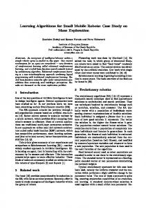
1cm
Figure 1. Photograph showing relative sizes of the MiniWhegs IV robot and a Blaberus gigantius cockroach. they offer much of an advantage over wheels because at this small scale it is difficult to implement a modern track suspension [1]. Fukui et al. [6] developed a small hexapod robot that uses piezoelectric actuators to run in a tripod gait. The vehicle is limited to relatively flat surfaces because its legs have short ranges of motion. It is difficult for small robots to move through realworld terrain simply because of the relative size of the obstacles they must overcome. Therefore, it is particularly important for small robots to use efficient locomotory appendages. For a given vehicle size, legs promise the greatest mobility because they enable discontinuous contact with the substrate, which is important for uneven terrain. Insects are excellent examples of highly mobile, legged vehicles and therefore a robot designer would be well advised to draw inspiration from them. Biological inspiration can be implemented in varying degrees from the direct to the abstracted [13]. The direct approach sometimes requires that new technologies be developed, whereas abstracted locomotion principles can often be implemented using current technology. The design of Sprawlita [4] was inspired by the cockroach. At 16cm long, it is larger than the other robots described here. It is a hexapod that uses a combination of servo motors and air cylinders. Its top speed of 4.5 body lengths per second is very fast as compared to existing
robots, but it is not autonomous and because it uses 6 bars of air pressure it is unlikely to become so. Birch et al. [2] developed a 7.5cm long hexapod inspired by the cricket and actuated by McKibben artificial muscles. It walks using 2 bars of air pressure, but again, the compressor is not onboard the vehicle. RHex [14], [15] and Whegs [12] ( R. Quinn, patent pending) are good examples of larger (50cm long) hexapods that use abstracted cockroach locomotion principles to great effect. RHex preceded Whegs and uses six motors to independently rotate its legs. At 3 body lengths per second, the Whegs vehicles are several times faster than other legged robots of similar size and can climb obstacles that are 1.5 leg lengths tall. A key to their success is that they use just one propulsion motor and rely on preflexes to adapt their gaits to different terrain [10]. Their driving appendages are called “whegs,” which have three spokes and combine the speed and simplicity of wheels with the climbing mobility of legs. This paper describes novel small robots (less than 10cm) called Mini-Whegs that are highly mobile, robust, and power autonomous. Their basic design is derived from the Whegs concept, but modifications were made to reduce size and improve mobility. These 9cm long robots can run at sustained speeds of over 10 body lengths per second and climb obstacles higher than the length of their legs. One version, called Jumping Mini-Whegs, also has a self-resetting jump mechanism that enables it to surmount obstacles as high as 22cm, such as a stair. 2.0 Methods and Design The overall design goals for the Mini-Whegs robot series are functionality, simplicity, compactness, and durability. All Mini-Whegs robots are similar in size and weight, and have two axles with two three-spoke whegs each. A single propulsion motor drives both axles. The chassis consists of a rectangular frame that houses the main systems, including the drive train, steering components, batteries and the onboard RC components. Jumping Mini-Whegs is designed specifically to demonstrate that jumping ability can be added to the smallest “Whegs” platform. It is very similar to the other Mini-Whegs robots, but includes an additional jumping mechanism and forgoes steering and radio control components. As the robot runs, the jumping mechanism slowly retracts, releases, and then repeats. The robot uses the same single drive motor and transmission used by other Mini-Whegs robots to simultaneously power both the running and jumping functions. An additional gear reduction was added to provide sufficient torque to wind the spring-activated jumping mechanism.
2.1 Legs Three-spoke whegs were developed to propel the full sized Whegs robots. The spokes of each wheg are spaced 120 degrees apart and two whegs are mounted on each axle. Contralateral pairs of whegs are nominally positioned 60 degrees out of phase with each other. Whegs robots have a total of three axles, each 60 degrees out of phase with its neighbor. One motor drives all three axles via chains and sprockets so that Whegs robots walk in a cockroach-like nominal alternating tripod gait. Whegs robots also have compliant mechanisms in their axles that enable the whegs to passively change their phase by as much as 60 degrees [12]. The result is that their gaits passively adapt to the terrain, and they climb with contralateral legs in phase, in a manner similar to the climbing movements of a cockroach [16]. Because of its design goals of compactness and simplicity, Mini-Whegs uses only four whegs. In MiniWhegs IV, they are each machined from a single piece of Delrin (Fig. 2). This design allows for a certain amount of compliance under normal operation due to the flexible polymer material and slender spokes. Earlier robots in the series used rigid whegs fixed to the central axle through a flexible coupling system, similar in concept to that on the full-sized Whegs robots. This mechanism allowed a limited amount of torsional compliance between the axle and whegs, but at this small scale the coupling was subject to failure under the high loads experienced during climbing. Original whegs designs used a sharp tipped foot, which penetrated carpet and other yielding surfaces to provide good traction. However, this foot sometimes snagged on the substrate and caused the vehicle to somersault into the air. To solve this problem, the whegs were redesigned with a foot that consists of an arc segment that follows the circumference of the whegs. Theoretically, the length of each foot could be increased from 0 to 120 degrees—in other words, from bare spokes to a complete wheel. However, as the length of the foot is increased, the climbing ability of the robot is diminished. In the limit, it would provide the speed and smooth ride of a wheel, but also with the poor climbing performance of a wheel. A short segment length of 25 degrees was chosen to provide enough surface area to prevent snagging on softer surfaces without sacrificing significant climbing ability. While the spokes of the rear whegs occupy a purely vertical plane, the front ones are splayed outward so that they rotate in a cone (Fig. 2). This design allows for greater clearance of the frame of the robot for a tighter turning radius. Additionally, a slight splay aids in the lateral stability of the robot by widening its stance. Full et
2.3 Steering 3.6cm
Figure 2. Rendering of the Mini-Whegs IV front wheg and steering joint design. al. describe the advantages of such a sprawled posture in cockroaches [7]. 2.2 Chassis and Drive Train The rectangular frame of Mini-Whegs contains a single 1.2W Maxon DC drive motor with 67:1 planetary transmission, the drive train, steering components, batteries and control system. The frame itself consists of two Delrin side rails with aluminum cross-braces on the top and bottom. The side rails are precisely machined to support nearly every component inside the robot, including axle bearings, motor mounts, battery supports, and the steering servo and rack. The physical dimensions of the Mini-Whegs IV chassis are 9.0cm long by 6.8cm wide by 2.0cm thick with attached 3.6cm radius whegs. The robot’s mass is 146g, including batteries. Mini-Whegs robots have two axles connected to one drive motor via non-slipping stainless steel drive chains. This non-slipping drive connection is necessary because the correct phase offset between front and rear axles must be maintained in order to achieve a nominal alternating diagonal gait. The use of one motor and chain drive to propel the robot has the additional advantage that all of the onboard power can be delivered to a single wheg when the others are slipping on the substrate.
The basic design of the steering mechanism for MiniWhegs is similar to the system in an automobile. Each front wheg rotates in a bearing, which is supported by a steering arm. A servo actuated sliding rack connects to the steering arms with a slot and pin. The steering arms pivot in mountings on the aluminum chassis cross braces to provide a steering motion. A rendering of the steering layout for Mini-Whegs IV is shown in Figure 2. Since all four whegs are driven, the front axle must transmit power to the whegs and still allow for steering movement. We explored using flexible materials for this application in earlier versions of Mini-Whegs. As discussed in Section 2.1, these components were designed to serve the dual purpose of providing torsional compliance for automatic gait adaptation. Mini-Whegs IV forgoes axle-based torsional compliance for greater precision and strength. To provide a strong and reliable steering system for Mini-Whegs IV, a simplified universal joint was designed for each front wheg using no flexible components (Fig. 2). The joint consists of a ball at either end of the front axle inserted into a brass cup, which is mounted in the steering arm bearing. A pin attached to the ball slides in a slot in the brass cup to transfer torque while allowing the cup to pivot around the ball. Dimensions of steering arms and other components were designed to allow the maximum pivoting travel given certain clearance and servo travel limitations. 2.4 Design: Jumping Mini-Whegs Jumping Mini-Whegs is similar in design and construction to the other Mini-Whegs robots, with some key differences. The purpose of the robot is simply to prove the jumping concept, so steering and control components were left out. The Delrin sides of the robot are similar in design and function, but they support the additional components of the jumping mechanism. These components include a secondary 275:1 transmission, and a parallel four-bar jumping mechanism attached to the frame via two axles. The parallel four-bar jumping mechanism was chosen for several reasons. First, the prescribed motion of the spiked lower bar, or “foot,” propels the robot forward and upward—a desirable trajectory for obstacle clearance. Second, it is able to fold to a compact position between jumps, allowing the robot to run swiftly like any other Mini-Whegs robot. The spring attachment position allowed for the testing of different lever arm lengths and spring stiffnesses.
2.5 Control System and Operation
Figure 3. Photographs illustrating the parallel four-bar linkage used in Jumping Mini-Whegs. In Jumping Mini-Whegs, the whegs are driven via the same drive motor and transmission combination as a standard Mini-Whegs robot. Two sets of chains and sprockets drive the front and rear axles. However, a third chain runs a custom manufactured input shaft for the additional Maxon 275:1 planetary transmission, which outputs a slow, high torque motion. The total gear reduction for the jumping mechanism is 18,545:1. An aluminum 14-tooth gear with several teeth removed, or “slip-gear,” is mounted on the output shaft of this transmission. It interfaces with an unmodified gear of the same size that is attached to one of the rotating crossbars in the four-bar mechanism. Running the motor turns the slip-gear, thereby rotating the four-bar mechanism and storing energy in the spring. The slip-gear is calibrated so that the teeth will remain in contact with the mechanism gear just long enough to wind the mechanism to its closed (loaded) position. The slip-gear continues to rotate and reaches the gap where the teeth have been removed; at which point it can no longer wind the unmodified gear attached to the four-bar mechanism. Since the motion of the mechanism is now unconstrained, the large spring force causes it to suddenly release to its open (unloaded) position. The slip-gear then re-engages and restarts the winding process.
Control of Mini-Whegs IV is accomplished via a RC transmitter and a sub-micro receiver. A separate microspeed controller is employed for bi-directional throttle control. A Cirrus micro-servo is used to actuate the steering motion. Mini-Whegs robots use two 3V CR2 lithium batteries connected in series for all power needs. These cells were chosen because of their high power density relative to their size and weight, for their flat power curves and for their capacity to deliver very high current on demand. Because of its straightforward design, Mini-Whegs IV is easy to operate. A small switch turns on the robot and a radio control transmitter is then used to control steering and throttle. For the purposes of proving the jumping concept, Jumping Mini-Whegs was designed without steering or any active control system, so it is limited to moving forward in a straight line. Control and actuation of jumping are accomplished mechanically via the slip-gear mechanism. The robot is simply turned on with a switch and then automatically runs, jumps, and repeats until it is turned off. 3.0 Results The primary advantage of whegs over wheels is increased mobility on uneven terrains. Because of the three-spoked geometry, a Mini-Whegs robot can climb over obstacles at least 1.5 times as tall as the radius of the whegs. An obstacle less than one radius high easily stops the same robot fitted with wheels of the same size instead of whegs. 3.1 Mini-Whegs IV In addition to being maneuverable and capable of surmounting large obstacles, the 9cm long Mini-Whegs robots are fast, running at over 10 body lengths per second (90cm/s). With wheels substituted for whegs on the same chassis, speeds up to 50 percent faster have been attained. The reduced speed of whegs locomotion is a worthwhile tradeoff for the increase in mobility. MiniWhegs excels in rough terrain such as dirt or grass, where speeds nearly as high as those on smooth terrain are observed. The turning radius using whegs depends upon the orientation of the whegs at the beginning of the turn, but can be as tight as 2.0 body lengths (17.8cm) or as large as 3.1 body lengths (27.9cm). The turning radius of the robot when using wheels is consistently 2.5 body lengths (22.9cm)—equal to the average turning radius using whegs.
battery life is encountered than in other Mini-Whegs robots. The automatically resetting mechanism for repeated jumping works consistently and reliably once properly calibrated. The ideal mechanism uses a relatively soft spring with significant preload in order to store and release the maximum possible energy for the jump, given a certain maximum available motor torque. Figure 4. Composite of video frames showing MiniWhegs IV traversing two 3.8cm high by 8.9 cm wide obstacles while running at 3 body lengths per second. In addition to being extremely mobile, Mini-Whegs is also robust and versatile. These lightweight robots have been dropped from a height of 10 or more body lengths, and have tumbled down flights of concrete stairs with no damage. Because of the low profile of the robot frame, Mini-Whegs can also operate while upside down, if necessary. It is possible for the robot to become inverted when climbing a very large obstacle due to its high power and traction, or it could potentially land upside down after a fall. While inverted, radio control becomes less intuitive, and traction is somewhat reduced due to the non-optimal foot and steering orientation. In order to return the robot to normal upright operation, the operator can drive the vehicle into a large obstacle, so that it flips again. 3.2 Jumping Mini-Whegs Tests demonstrate that Jumping Mini-Whegs can leap 22cm (2.5 body lengths) high, which is greater than the height of one standard stair. Because of the high load experienced while winding the spring, somewhat less
Figure 5. Composite of video frames showing Jumping Mini-Whegs clearing a 15cm high stair.
4.0 Discussion and Future Work Relative to body length, Mini-Whegs robots are significantly faster than other legged robots [15]. Their design allows each leg to swing higher than the body so greater obstacles can be surmounted. Not only is a MiniWhegs robot faster and more mobile than other legged robots of similar size, it is power autonomous and has fully wireless operation. In future work we will address problems that we have observed in testing the vehicle. Mini-Whegs robots have some difficulty traversing certain substrates, primarily those that allow the whegs to penetrate and catch, such as slatted surfaces or tangled obstacles like brush or cable, which can get caught in the whegs. Additionally, because of the low friction coefficient of the Delrin whegs, the robot tends to slip on hard or polished surfaces. Future versions will use feet coated with a layer of high friction material to allow greater operating speeds on these surfaces, with no negative effects on softer surface traction. Current versions of the robots are not designed to be waterproof, but future chassis designs will be sealed to perform in a greater range of outdoor conditions. Systems for autonomous operation are under development and will be part of the future progression of the Whegs and Mini-Whegs robots. Mini-Whegs robots have previously carried more than twice their own body weights in payload, so they are ideal platforms for testing sensor and control packages [11]. Jumping Mini-Whegs was designed to prove that jumping could be achieved on a robot of this scale, and that the same motor could power both running and jumping. As such, the repeated running and jumping sequence is not flexible. Future designs will separate these two functions to achieve independent and controllable operation. Jumping Mini-Whegs is designed to run on either side, but only jumps when upright, rather than in an inverted orientation. When the robot lands from a jump in that orientation, it cannot run with full effectiveness until the four-bar mechanism is retracted most of the way. If the robot lands in an inverted position, it can run unhindered as the mechanism retracts, but cannot perform its next jump unless it is righted. Jumping Mini-Whegs II will address these issues by winding the jump mechanism
many times faster, and by providing full user control. This will allow the robot to be piloted into a right-side-up configuration using the terrain, as described in Section 3.1. The uses of a small, yet capable, mobile robot are numerous. One such example is in insect inspired navigation research, for which mainly small, wheeled robots are currently used. A more mobile small robot platform could be useful. Full sized Whegs robots have already been successfully used as outdoor sensor platforms [8]. However, in some cases a small robot is necessary to fully investigate certain biological phenomena, e.g. cricket phonotaxis. Mini-Whegs and Jumping Mini-Whegs provide viable and highly adaptable platforms for outdoor locomotion. Acknowledgments This work was supported by Air Force contract F08630-01-C-0023, DARPA, and NSF/IGERT grant DGE-9972747. The authors also wish to thank Charles P. Althoff, David N. Johnson, and Nicholas J. Didona for their valuable contributions. References [1] Bererton C., Navarro-Serment, L.E., Grabowski, R., Paredis, C.J.J., Khosla, P.K., “Millibots: Small Distributed Robots for Surveillance and Mapping,” Government Microcircuit Applications Conference, March 2000, pp. 20–23. [2] Birch, M.C., Quinn, R.D., Ritzmann, R.E., Pollack, A.J., Philips, S.M., “Micro-robots inspired by crickets,” in Proceedings of Climbing and Walking Robots Conference (CLAWAR ‘02), 2002, Paris, France. [3] Caprari, G., Arras, K.O., Siegwart, R., “The autonomous miniature robot alice: from prototypes to applications,” in Proceedings of 2000 IEEE/RSJ International Conference on Intelligent Robots and Systems, vol. 1, 2000, pp. 793–798. [4] Clark, J.E., Cham, J.G., Bailey, S.A., Froehlich, E.M., Nahata, P.K., Full, R.J., Cutkosky, M.R., “Biomimetic design and fabrication of a hexapedal running robot,” in Proceedings of 2001 IEEE International Conference on Robotics and Automation, vol. 4, 2001, pp. 3643–3649. [5] Drenner, A., Burt, I., Dahlin, T., Kratochvil, B., McMillen, C., Nelson, B., Papanikolopoulos, N., Rybski, P.E., Stubbs, K., Waletzko, D., Yesin, K.B., “Mobility enhancements to the scout robot platform,” in Proceedings of 2002 IEEE International Conference on Robotics and Automation, vol. 1, 2002, pp. 1069–1074. [6] Fukui, R., Torii, A., Ueda, A., “Micro robot actuated by rapid deformation of piezoelectric elements,” in Proceedings of 2001 International Symposium on
Micromechatronics and Human Science, 2001, pp. 117–122. [7] Full, R. J., Blickhan, R., Ting, L.H., “Leg design in hexapedal runners,” J. exp. Biol., 158: 369–390. [8] Horchler, A. D., Reeve, R. E., Webb B. H., Quinn, R. D., “Robot Phonotaxis in the Wild: a Biologically Inspired Approach to Outdoor Sound Localization,” 11th International Conference on Advanced Robotics, (ICAR ’03), 2003, Coimbra, Portugal. [9] K - T E A M SA Headquarters Switzerland, Chemin du Vuasset, CP 111, 1028 Préverenges, Switzerland. [10] Loeb, G.E., Brown, I.E., Cheng, E.J., “A hierarchical foundation for models of sensorimotor control,” Exp. Brain Res., 1999, 126: 1–18. [11] Morrey, J.M., Horchler, A.D., Didona, N., Lambrecht, B., Ritzmann, R.E., Quinn, R.D., “Increasing Small Robot Mobility Via Abstracted Biological Inspiration,” in Video Proceedings of 2003 IEEE International Conference on Robotics and Automation, Taiwan. [12] Quinn, R.D., Kingsley, D.A., Offi, J.T., Ritzmann, R.E., “Improved Mobility Through Abstracted Biological Principles,” in Proceedings of 2002 IEEE International Conference On Intelligent Robots and Systems, 2002, Lausanne, Switzerland. [13] Quinn, R.D., Nelson, G.M., Ritzmann, R.E., Bachmann, R.J., Kingsley, D.A., Offi, J.T., Allen, T.J., (in press), “Parallel Strategies For Implementing Biological Principles Into Mobile Robots,” I n t . Journal of Robotics Research. [14] Saranli, U., Buehler, M., Koditschek, D., “Design, modeling and preliminary control of a compliant hexapod robot,” in Proceedings of 2000 IEEE International Conference on Robotics and A u t o m a t i o n , San Francisco, CA, 2000, pp. 2589–2596. [15] Saranli, U., Buehler, M., Koditschek, D., “RHex: a simple and highly mobile hexapod robot,” Int. J. Robotics Research, 20(7): 616–631. [16] Watson, J.T., Ritzmann, R.E., Zill, S.N., Pollack, A.J., “Control of obstacle climbing in the cockroach, Blaberus discoidalis: I. Kinematics,” J. Comp. Physiology, 2002, 188: 39–53.