This is the Pre-Published Version
Accepted Manuscript Efficient slicing procedure based on adaptive layer depth normal image Long Zeng, Lip Man-Lip Lai, Di Qi, Yuen-Hoo Lai, Matthew Ming-Fai Yuen PII: DOI: Reference:
S0010-4485(11)00145-X 10.1016/j.cad.2011.06.007 JCAD 1794
To appear in:
Computer-Aided Design
Received date: 10 March 2011 Accepted date: 14 June 2011 Please cite this article as: Zeng L, Lai LM-L, Qi D, Lai Y-H, Yuen MM-F. Efficient slicing procedure based on adaptive layer depth normal image. Computer-Aided Design (2011), doi:10.1016/j.cad.2011.06.007 This is a PDF file of an unedited manuscript that has been accepted for publication. As a service to our customers we are providing this early version of the manuscript. The manuscript will undergo copyediting, typesetting, and review of the resulting proof before it is published in its final form. Please note that during the production process errors may be discovered which could affect the content, and all legal disclaimers that apply to the journal pertain.
An efficient construction algorithm for RP layered model is proposed based on LDNI.
Solid is converted into LDNI representation which is a layered and ordered point
cloud. Boolean operation is performed on 1D segment in LDNI. Loops are constructed according to three simple rules. Mesh with 2 million triangles can be sliced in 2.5 seconds.
Click here to view linked References
Efficient Slicing Procedure based on Adaptive Layer Depth Normal Image Long ZENG, Lip Man-Lip LAI, Di QI, Yuen-Hoo LAI, Matthew Ming-Fai YUEN Department of Mechanical Engineering, Hong Kong University of Science and Technology, Hong Kong SAR, P.R. China
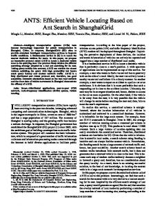
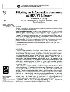
Abstract: In layered modeling for rapid prototyping of products, compromising slicing accuracy and time is a critical issue. Based on adaptive Layer Depth Normal Image (LDNI), this paper proposes an efficient algorithm to achieve this compromise for complex Constructive Solid Geometry (CSG) models. First, each primitive at the tree leaf is converted adaptively into a LDNI solid whose Boolean operation can be performed efficiently. Then, a layered model is constructed directly from the Booleaned LDNI solid since it is actually a set of layered and ordered point cloud. In addition to speed, efficient use of memory is also taken into account in design of the adaptive LDNI algorithm. The capability and efficiency of this slicing algorithm are demonstrated by examples. Keywords: rapid prototypes, layer manufacturing, layer depth normal image, constructive solid geometry. 1. Introduction Rapid prototyping (RP) is an important technology in support of product development. In a RP process, a solid model is created and sliced into layers and output to a RP machine via a STL model. As a STL model is a piecewise approximation of a solid model, there exists a trade-off problem: accuracy and efficiency. Accuracy issue arises in RP when a solid model surface is tessellated. This can be controlled by the chordal error [1] which is the maximum shape difference between the tessellated model and the original model. The efficiency is mainly the time cost of slicing algorithm in preparing the data for layer-by-layer deposition. As slicing algorithms for STL model are based on triangle-plane intersection algorithms, the accuracy and efficiency trade-off is apparent when the tessellated elements increase. Such trade-offs can be highlighted in complex tessellated CSG models such as the ring model shown in Fig. 1a. The model is tessellated with a chordal error of 2 m, the total number of triangles is 1102632. In conventional RP procedure, a mesh-based Boolean operation need to be performed first (Fig. 1b) before it is sliced into a layered model (Fig. 1c). However, the mesh Boolean process is usually time-consuming, and the resulted Boolean model could be ill-constructed with defects, such as gaps, degenerated facets, etc. LDNI [2] generates a layered point cloud model. It is an extension of LDI (Layered Depth Image) by assigning a unit normal vector to each of the sampled intersection points. LDI shoots an array of rays against the solid model and registers the multiple intersection points for each ray [3]. It can equally apply to a mesh model or a surface model efficiently with acceleration of standard graphic cards using standard OpenGL functions [4]. In this paper, an efficient adaptive LDNI slicing algorithm is proposed to achieve a compromising solution for the aforementioned trade-off problem. Firstly, adaptive Boolean operation is applied to the 1D segments of the adaptive LDNI sampled solids. Secondly, layered loop construction is applied to the Booleaned LDNI solid consisting of layered ordered point
cloud.
(a)
(b)
(c)
Fig. 1. Normal slicing procedure for a CSG ring model: (a) original model before Boolean; (b) Booleaned model; (c) sliced model Section 2 of the paper reviews the related work on the slicing technique. An overview of the adaptive LDNI slicing algorithm is presented in section 3. The two major components of the adaptive LDNI slicing algorithm, adaptive LDNI Boolean and layered-loop construction, are detailed in section 4 and section 5 respectively. Efficiency of the algorithm is discussed in section 6 with support of examples. Finally, section 7 gives a summary and future work. 2. Related work Rapid prototyping is an efficient technology to convert a digital model to a physical model using the layered deposition technique [5]. The slicing procedure is an integral step of the RP process, consisting of model creation, slicing, path generation, layer-by-layer deposition, and post processing [6]. STL model is the most commonly form of RP input. In preparing a layered model, the accuracy and efficiency are always the major concern. The solutions addressing this concern can be generally classified into four categories. The first category is adaptive slicing, which enhances the slicing efficiency by reducing the number of layers. The adaptive slicing algorithm generates a variable slicing thickness given the local surface geometry or a given smoothness requirement. Dolenc and Makela [7] proposed the cusp height, which is a widely accepted concept, to describe the maximum deviation in RP manufacture. Within the user given maximum allowable cusp height, the thickness of current layer is predicted by point normal around the boundary of the last horizontal plane. Sabourin et al. [8] adopted the cusp height as a criteria and computed each slab thickness by recursive subdivision until the layers thickness under a given tolerance. This was further extended by Yan et al. [9], who obtained a higher efficiency using a non-uniform cusp height as a criteria. Mani et al. [10] proposed a region-based adaptive slicing, where the given model surface is classified into critical surfaces which are adaptively sliced, and non-critical surfaces, such as part interior, which are sliced using the maximum allowable layer thickness. Although adaptive slicing can alleviate the staircase quality problem and improve the slicing efficiency, the approximation error still exists during the tessellation step. Thus, adaptive slicing techniques are always used in combination with direct slicing techniques (see the hybrid category for more details). The second category is direct slicing, which generates contours directly from the original input model without any model representation conversion. It avoids the approximation error that happens in the tessellation step. For NURBS models, Rajagopalan et al. [11] proposed a direct slicing method using the complete geometric representation. For freeform surfaces, Chakraborty
et al. [12] output a layered file directly based on a surface-plane intersection algorithm. For point cloud models, Liu et al. [13] proposed an error-based segmentation method for direct RP. The point cloud data is first subdivided into regions and feature points are identified in each region. These feature points are used to construct an intermediate point-based curve model, where the RP layer contours are directly extracted. This method is further improved by Kumbhar [14] and applied to reverse engineering. The point cloud considered by Liu et al. and Kumbhar is unordered. However, in practice, points in some model representations are ordered and layered, such as the point cloud from medical scanning (see section 4.1). Whatever the input, be it a STL model; a surface model or a CSG model, it can be efficiently converted into a LDNI model with controllable conversion error using built-in graphic card acceleration. The third category is extra-interpolation slicing, which usually fits the layered polygon contour with a biarc curve or a NURBS curve to improve the contour precision [15]. To reduce errors between the fitting curve and the sectional curve sliced from the original CAD model, Zhao et al.[16, 17] proposed a two-step method. The first step is to compute an interpolation curve to approximate the original curve in its normal section using the position of the two vertices and their tangent vectors. Then, points of the slice contour are obtained by calculating the intersection points between the interpolation curve and the slice plane. The last category is the hybrid slicing algorithms, which are combinations of the above three slicing techniques. Since direct slicing technique can avoid the major approximation error occurring in the tessellation process and the adaptive slicing technique can improve the slicing efficiency, they are usually combined. Wu et al. [18] proposed an adaptive slicing algorithm for point cloud data. It projects all points between two consecutive horizontal planes into a mid-plane. These projected plane-points are then fitted by a polygon curve and the shape error is expressed as the distances between the points and the polygon curve. If the computed shape error is less than a user-defined threshold, then the current layer thickness is increased until this shape error is very close to the threshold value. However, the shape error definition is not invariant under point density. Yang et al. [19] and Qiu et al. [20] proposed an adaptive slicing algorithm based on curvature information of a MLS (Moving Least Square) surface. For NURBS surface, Ma et al. [21] also combined an adaptive scheme according to surface curvature information. The proposed adaptive LNDI algorithm has the ability to directly slice CSG solids robustly and efficiently. Similar work was done by Sashidhar et al. [22], which constructs a layered model directly by computing planar analytic intersection curves while hierarchically traversing the CSG tree. Their method is limited to several regular CSG primitives since it is time-consuming to compute an analytic intersection between a free form model and a plane. Yan and Gu [23] proposed a more efficient method based on a ray tracing technique, where the intersection between a ray and a primitive were computed efficiently. This idea was further extended by W. K. Chiu, et al. [24] and W. M. Zhu et al. [25], where each primitive is represented in a ray representation, dexel. Thus, the Boolean operation for dexel model is also simplified from 3D to 1D segments Boolean operation. The proposed adaptive LDNI algorithm has the advantage over these algorithms in that each CSG primitive is represented as an adaptive LDNI, which have sample point normal information to enhance the algorithm’s robustness. An additional advantage is the proposed algorithm is memory efficient as adaptive LDNI only stores each primitive’s sample points in its own range.
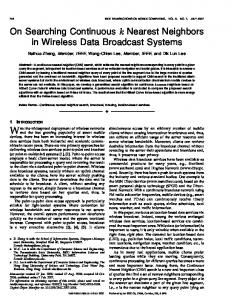
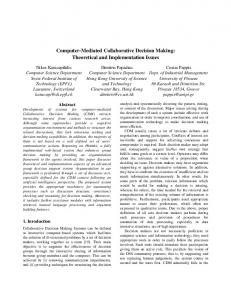
In the proposed adaptive LDNI slicing algorithm, the input model is assumed to be a homogeneous object while discussion of slicing technique for heterogeneous objects can be found in [26]. The slicing direction in the proposed prototype system can be set manually to axis-aligned direction or automatically after Byun et al. [27]. 3. Overview For resolving the above compromising issue, a new slicing procedure based on adaptive LDNI is proposed. The algorithm requires a preset slicing direction and consists of two steps which are illustrated with a simple CSG tree model shown in Fig. 2: Adaptive LDNI Boolean Each component in the CSG model (Fig. 2a) is converted into a LDNI solid, adaptively (Fig. 2b) assisted by graphic card acceleration. The depth and normal information of each intersection point between the LDNI ray and the primitive are read directly from the pixel’s depth and color buffer respectively. Thus each component can be tessellated with small approximation error and minimum loss of efficiency as no triangle-triangle intersection computation is necessary. Instead, the traditional 3D mesh Boolean operation is converted into 1D segments Boolean operation. It is more robust since the normal information in LDNI solid can help the point membership classification process (Fig. 2c). Layered loop construction Since the input point cloud from the first stage is a layered, ordered, and classified point cloud (IN: red point; OUT: green point, shown in Fig. 2c), each layer-loop can be easily obtained by connecting the points with the assistance of the 1D neighborhood information (Fig. 2d). The 1D neighborhood information is derived from the universal continuous principle (introduced in section 5).
Fig. 2. Overview of the efficient slicing procedure based on adaptive LDNI
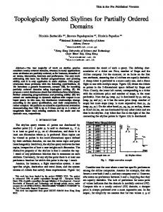
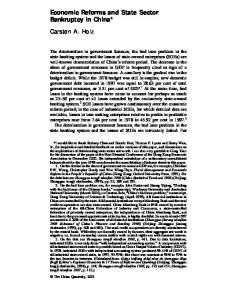
Compared with the previous mesh based slicing procedure under the same accuracy, the efficiency of the proposed slicing algorithm is manifested by its lower storage and much less time to generate a layered model (in .SLC file format) for fabrication, even for a complex CSG product. 4. Adaptive LDNI Boolean Suppose the input model is a faceted surface model whose tessellation is controlled by chordal error λ (shown in Fig. 3a), defined as the Hausdorff distance between the tessellated model and the original model. The facet number will increase dramatically when λ decreases. For a sphere
with radius 1mm shown in Fig. 3b to Fig. 3c, the mesh facet number increased from 1572 faces to 20052 faces while λ is changed from 0.01mm to 0.001mm. Thus, an efficient LDNI Boolean operation with slicing procedure is introduced, which is dependent on the ray resolution but almost independent of the facet number.
(a) Chordal error λ
(b) λ=0.01mm, 1572 faces
(c) λ=0.001mm, 20052 faces
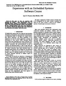
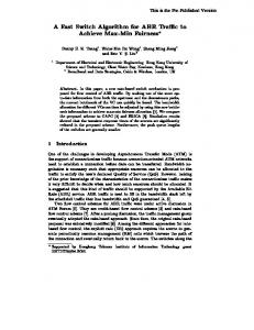
Fig. 3. Chordal error based tessellation for a sphere with a radius of 1mm 4.1. Adaptive LDNI solid LDNI solid is a layered point cloud model constructed efficiently with the help of a graphic card’s rendering pipeline. First, it renders the input model under a special rendering configuration. Then it is sampled with a certain resolution, denoted as LDNI resolution. In practice, LDNI resolution is represented by two variables: layer thickness, Dlayer, and ray width, Dray. As shown in Fig. 4a, if the left-bottom point of the sphere’s Enlarged Bounding Box (EBB) is (0, 0) and right-top point is (Width, Height), then the view-port is a screen rectangle which contains an array of Total_rays rays in the horizontal direction and Total_layers layers in the vertical direction. The Total_rays and Total_layers are computed by , (1) Where Width and Height are the width and height of the EBB. In the following example, the rendering environment configuration is specified by LDNI resolution, Width, and Height. The unsorted depth and normal value is read from the depth buffers and color buffers. A detailed view of the ith layer in Fig. 4b shows that the depth value and the normal vectors (blue arrow at point A and B) are retrieved. The coordinates (x, y, z) of a sample point A on the jth ray in the ith layer can be computed as: x = j /Total_rays*Width of EBB (2) y = depth value of A*Depth of EBB (3) z = i /Total_layers*Height of EBB (4) Where Depth is the depth of the EBB.
(a)
(b)
Fig. 4. Adaptive LDNI solid generation. (a) Rendering environment setup, ray direction is perpendicular with the paper; (b) detailed view of the ith layer (IN: circular point; OUT: triangular point). In this paper, there are several major modifications compared to the previous LDNI techniques [2, 3, 28] since it is applied to slicing procedure. Firstly, a single LDNI is adopted instead of the original three LDNIs (x-LDNI, y-LDNI, and z-LDNI) for speed efficiency. This is because a much higher resolution is used (800*800 in most cases) in the slicing procedure. Though some small features (gap or thin-shell) will be lost, this is acceptable in RP since such a small feature cannot be processed in RP. Secondly, the original LDNI is modified into a memory efficient technique, denoted as adaptive LDNI. In a CSG model with multiple components, the Normal LDNI adopts the Global EBB (GEBB), as shown in Fig. 5, which contains all the components instead of the LBB (Local Bounding Box). And the ray correspondence is automatically created. However, the amount of memory space required by each LDNI solid becomes a problem when the component number increases. For example, for a sphere in 800*800 LDNI resolution (this resolution is normal in our projects), the data from depth buffer (4 bytes) and color buffer (3 bytes) need to be stored in a LDNI solid. The storage needed is about 4.5MB (Megabytes). If the CSG model is composed of 400 components and each component needs two depth buffers (at least), 3600MB will be required to store the LDNI solids. This is a considerable burden for desktop computers (this component scale is not unusual in items such as jewelry design). Therefore, the Adaptive LDNI is proposed to store only the necessary information for each component. Taking the CSG model shown in Fig. 5 for example, it contains components A, B, and C. For each component, when it is converted into a LDNI solid, only the data whose corresponding pixel contained in its LBB is stored. Thus, our scheme is to create a map between the GEBB and LBBs. This can be easily achieved by recording a pair of index (rayStartIndex, layerStartIndex) for each LBB. Such as for C component, rayStartIndex—the ray index in GEBB of the ray which first intersect with C. layerStartIndex—the layer index in GEBB of the layer which first intersect with C. Then, the corresponding global position of the ith local ray in C can be computed by (rayStartIndex +i) th ray.
Fig. 5. Adaptive LDNI converts an object in its LEBB instead of the GEBB. Thirdly, intersection points are classified into IN/OUT with the help of normal information from LDNI (this is similar to the method used in dexel model [24, 25]). As shown in Fig. 4b, the blue arrows are the unit normal vectors of the sample points, and the gray arrow is the ray direction. If the dot product between a sample point’s normal vector and the ray direction vector
is less than zero, then this sample point is colored as IN (circular red color, such as sample point A); otherwise, it is classified as OUT (triangular green color, such as sample point B). These classified points are useful in the loop construction step. 4.2. LDNI Boolean The LDNI Boolean is performed layer-by-layer and ray-by-ray. The 1D ray Boolean operation is computed by hierarchically traversing the CSG binary tree. The ray intersection mainly consists of three steps (shown in Fig. 6): firstly, classify the end points of intervals rA(i, j) with respect to the intervals rB(i, j) as outside/inside; intervals rA(i, j) means the intervals on the ith ray of the jth layer of primitive A. Secondly, do the same classification for the end points of rB(i, j) with respect to the intervals rA(i, j). Finally, construct the resultant intervals according to the following rules: If rA(i, j) union rB(i, j), keep the outside end points of both rA and rB. If rA(i, j) intersect rB(i, j), keep the inside end points of both rA and rB. If rA(i, j) subtract rB(i, j), keep the outside end points of rA and inside end points of rB. If rB(i, j) subtract rA(i, j), keep the outside end points of rB and inside end points of rA. The outside/inside classification is only conducted on the Depth coordinate since the rays with the same global index have the same width and height coordinates. Thus, is considered inside the interval when and ; is outside the interval when and , where =10e-4 is chosen in our implementation. The special cases happen when or . However, this can be handled easily using the neighborhood information [29] with the help of normal information of each sample point. An illustration of the LDNI Boolean operation is given in Fig. 6.
Fig. 6. Ray Boolean operation (IN: circular point; OUT: triangular point) Fig. 7 is a simple example demonstrating the application of the adaptive LDNI solid and LDNI Boolean operation introduced in this section. Since the LDNI solid is constructed by putting a single camera at the scene (left to right in this example), some of the points in the perpendicular direction at the base of the Athena model (Fig. 7a) are lost (Fig. 7b and Fig. 7c). However, this can be handled successfully in the post loop construction process.
(a) Athena subtract torus
(b) LDNI solids
(c) LDNI Boolean result
Fig. 7. LDNI Boolean results of Athena subtracting a torus 5. Loop construction The main purpose of loop construction is to find the correct connectivity for each sample point. 5.1. Rules for loop construction Several simple rules are proposed to lay down the mathematical foundation for loop construction. Definition 1 Continuous 1D-neighborhood: On a line (Fig. 8a), the continuous 1D -neighborhood for a reference point is an open interval, which is the intersection between the line and an open disk centered with the given point and radius . According to the continuity definition in calculus, the point number in its -neighborhood is infinite and if the reference point is tagged, there exists a small positive value , and all the points in the -neighborhood must have the same point type with the reference point. If this definition is extended to a 1D discrete set, we get Definition 2 Discrete 1D-neighborhood: In a discrete set on a line (Fig. 8b), the discrete 1D -neighborhood for a reference point is a finite point set, where is the sample resolution with . Here, is to guarantee that a point’s -neighborhood is not an empty set. For the case of a partial neighborhood, either the left- or right-neighborhood may be empty. In such case, the reference point is called the turning point, such as the points on the first or last ray. This case will be handled differently in the loop construction process. Thus, similar properties for the reference point can be derived from definition 2: If a reference point is an internal point, there exists one left and one right nearest point having the same point type as the reference point. If a reference point is a turning point, there exists one left or one right nearest point having the same point type as the reference point.
Fig. 8. 1D-neighborhood for (a) continuous and (b) discrete cases Now, three simple rules for loop construction are introduced. Rule 1 Manifold principle: the input model is a valid manifold mesh model. Manifold mesh model means each ray must intersect the model even times (even number of times) and each point must have two connections to its left and right point. A valid manifold mesh model further restricts the input model to have no small features whose dimensions are less than the sample resolution . Otherwise, these small features will be ignored in the resulting RP model. The resolution is chosen to be better than the accuracy of most major RP machines. Additionally, this rule also implies the given model has a consistent orientation. It is important since the normal is used for the point type classification and to improve the algorithm robustness. Rule 2 1D-neighborhood principle: In a valid manifold model, a point on an internal ray may find its two connections at the two nearest neighborhood points on adjacent rays with the same point type (IN or OUT) under the prerequisite that there are no other points between them. A simple illustration of this principle is shown in Fig. 9. P1P2 is a valid connection. However, P1P3 is not since P4 is located between P1 and P3. In a LDNI solid, the principle can be derived from definition 2 and rule 1.
(a) Correct connection
(b) Incorrect connection
Fig. 9. Find point connectivity using the 1D-neighborhood principle In order to find the two connections of a turning point, we have, Rule 3 Half 1D-neighborhood principle: for a turning-point, one connection can be found on its left or right next ray according to rule 2. The other connection can be found on the nearest point on the same ray. As shown in Fig. 10a, one of the connections of the turning-point P1 is found, point P3, on the next ray according to rule 2, and the other, point P2, is found on the same ray according to rule 3. 5.2. Loop construction Before constructing the loops in each layer, the connections of each point are found. Since the input is a manifold model (rule 1), each point should only have two pointers: pre and post. If a CSG model has multiple loops in a single layer, it may be difficult to detect the turning-points. A better way is first finding the pre and post pointers for each point according to rule 2. Then, the connectivity of each point is checked. If its connections are less than two, we apply rule 3. After these two steps, each point (shown in Fig. 10a) can find valid points as its pre and post connections. If there are still points whose connections are less than two, they will be considered as invalid points and ignored (this may happen if the model has some defects). After the connections of each point are found, loops are constructed by tracing the point’s
connectivity information, as shown in Algorithm 1.1. The neighboring point in a loop is connected with a polyline, as shown in Fig. 10b. Algorithm 1.1 Layer-loop-construction While (there is still an unused point) Create a new loop, Lnew. Start point, Ps, is selected as an arbitrary point, and flagged as used. Do The next point Pn = Ps->post. If Pn is not NULL and unused Add to the new loop Lnew and flag as used. While (Pn not equal Ps)
(a) Find connections according to rule 2 and rule 3
(b) Connected loop
Fig. 10. Loop construction for one layer of the sphere in Fig. 4 6. Experimental results and discussions This slicing algorithm has been tested in the commercial software JewelCADPro [30]. Several tests are used to demonstrate the main features of this algorithm (Note that all the tests mentioned in this paper are run on a Window XP system PC with Intel® Core™ i5
[email protected], 2.86GHz, and 3GB RAM). TC is the time used to convert all primitives to adaptive LDNI solids according to the method described in section 4. TL is the time used to construct the layered loops using the method described in section 5. TT is the total time cost, equal to TC plus TL. The slicing direction can be selected from one of the standard axes for models in JewelCADPro. This section starts with some examples to show the main features of our algorithm. Then it is applied to two complex CSG models to demonstrate the algorithm’s capability and efficiency. We also compare the speed of our algorithm with that of InfinySlice [31] and Rhinoceros [32]. The Width, Height, and LDNI resolution for each example model are given. The unit for each model’s dimension is in millimeters (mm). For RP process, it is useful that the layer number can be computed indirectly from the parameters given. In the efficiency comparison of the algorithms, the layer number for the output layer model is adjusted to be equal. 6.1. Examples The first feature is that the algorithm’s speed efficiency is almost independent of the mesh density which relates to the chord error. This is tested and verified by the ring model shown in Fig. 11. The LDNI resolution is fixed to 0.0762mm*0.0762mm and the mesh density is varied (Fig.
11b). The algorithm time cost is listed in Table 1. From the table, the conversion time TC increases marginally since the LDNI solid conversion process needs to access all the face information on the original mesh model. However, the time cost on loop construction TL is almost constant since it only depends on the node number of the LDNI solid, which is only controlled by sample resolution. Therefore, the original surface model can be tessellated finely to decrease the approximation error while having little reduction in slicing efficiency. This model is also used to compare the algorithm efficiency against Rhinoceros, and InfinySlice.
(a) Original model
(d) Sliced model-3D view
(c) Sliced model-front view
Fig. 11. A ring model is used to test the effects of chordal error (λ) on the algorithm speed (LDNI resolution: 0.0762mm*0.0762mm; Width is 19.96mm, Height is 21.0mm) Table 1 Statistical data of Fig. 11 to show the effects of mesh density (LDNI resolution: 0.0762*0.0762) λ (mm)
Triangle #
0.1
Our algorithm
InfinySlice
Rhinoceros
TC (s)
TL (s)
TT (s)
TT (s)
TT (s)
1,530
0.109
0.188
0.297
1