orchestrate the cluster message ferry and global message ferry, ferry relay nodes (FRN) are deployed in every region. The remainder of paper is organized as ...
International Journal of Future Generation Communication and Networking Vol. 8, No. 4 (2015), pp. 307-318 http://dx.doi.org/10.14257/ijfgcn.2015.8.4.30
HMFS: A Hybrid Message Ferrying Scheme for Clustered Opportunistic Networks Zhang Yushu, Wang Huiqiang, LV Hongwu, Feng Guangsheng, Zhu Jinmei College of Computer Science and Technology, Harbin Engineering University, Harbin 150001 {zhangyushu, wanghuiqiang, lvhongwu, fengguangsheng, zhujinmei}@hrbeu.edu.cn Abstract Opportunistic network is an evolution of MANETs to delivery messages in intermittently connected or completely disconnected wireless networks. Message ferrying is an effective routing mode in opportunistic networks. However, the single message ferry routing scheme leads a much higher delay as the increasing of the network scale, comparing with that in small scale opportunistic networks. It has been proved that multiple message ferries routing scheme can improve the performance of large scale networks, but the problems of synchronization and coordinate between ferries have a bad effect on the routing efficiency. To solve these problems, a Hybrid Message Ferrying Scheme (HMFS) for clustered opportunistic networks is proposed. In HMFS, we divide the communication area into multiple regions based on clustering results and several cross zones containing the regions. A local ferry is deployed in each region to deliver messages in the region, and several global ferries are deployed according to horizontal and vertical zones to communicate among the regions. Moreover, each region has a ferry relay node in it, which is used to orchestrate the local ferry and global ferries. Through the theoretical analysis and simulation results, we can see that HMFS can improve the effect of routing in opportunistic networks in terms of network latency and delivery ratio. Keywords: message ferrying scheme; opportunistic networks; multiple ferries; network latency; delivery ratio.
1. Introduction Opportunistic networks are one of the most interesting evolutions of MANETs [1]. In opportunistic networks, wireless links between nodes cannot keep persistent due to node mobility, limited energy and interference. Since the traditional routing protocols are designed on the premise of the established end-to-end communication link from source node to destination node, they fails to deliver messages in opportunistic networks [2]. In opportunistic networks, the paradigm “store-carry-forward” is adopted to replace the using of traditional routing protocols. To communicate in such network environment, messages delivering must rely on the meeting opportunities created by nodes moving, and messages should be carried, till they get the chance to be sent to an intermediate node with a better chance to the destination. Considering the uncertainty of nodes movement, it is hard to optimize network latency and improve delivery ratio using the “store-carry-forward” routing [3]. Therefore, Message Ferrying (MF) is promoted to deal with this problem. MF is a kind of proactive opportunistic network routing scheme using ferries whose tracks and speeds can be controlled to carry and forward messages. It has been proved that MF scheme can effectively reduce latency and improve delivery ratio in opportunistic networks. Designing the appropriate moving path for ferries is the key to MF scheme.
ISSN: 2233-7857 IJFGCN Copyright ⓒ 2015 SERSC
International Journal of Future Generation Communication and Networking Vol. 8, No. 4 (2015)
Authors in [4] propose the basic design of the MF scheme and develop a general framework to classify variations of MF systems. In [5], local ferries are used to improve network performance and connectedness in DTMNs and there are several classes of messenger scheduling algorithms which can be used to achieve inter-regional communication in such environments. In HMFRS [6], a message ferry and a ferry access point are deployed in each DTN cluster, in which the ferry access point is utilized to orchestrate the message ferry and the global message ferry which connected the clusters. FGS [7], which exploits multiple local ferries and a global ferry to deliver messages, is proposed to minimize the average message delivery delay. Article [8] proposes cross-regional multiple messengers scheduling method to overcome the shortcoming of messengers scheduling and collaboration in traditional ferry routing. Compared with small scale opportunistic networks, the single message ferry routing scheme leads a much higher delay as the increasing of the network scale. While multiple ferries routing scheme can solve this problem, but more problems come, such as synchronization and coordinate between ferries. In this paper, a hierarchical ferrying routing scheme for clustered opportunistic networks is proposed, with the name of Hybrid Message Ferrying Scheme (HMFS). In HMFS, we divide the communication area into multiple regions based on clustering results. Local ferry (LF) node is deployed for each cluster to gather messages from ordinary nodes of the same cluster in each region. Global ferry (GF) nodes are deployed to delivery messages crossing different regions. In order to orchestrate the cluster message ferry and global message ferry, ferry relay nodes (FRN) are deployed in every region. The remainder of paper is organized as follows. In Section 2 we describe the network model and make several assumptions. In Section 3, Hybrid Message Ferrying Scheme is proposed. Section 4 is for the analysis of the delay in HMFS. In Section 5 simulations and results are shown. Section 6 gives the conclusion.
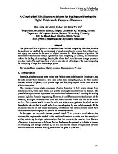
2. Network Model and Assumptions 2.1. Network Model In HMFS, communication area is divided into M ( M 2m 2m) square regions. Each region contains n ( n N / M ) nodes, a local ferry and a stationary FRN. The two adjacent columns of regions form a vertical zone, and the two adjacent rows form a horizontal zone. Every vertical zone or horizontal zone has one global ferry in it. A local ferry moves in its region and collects message from ordinary nodes in the same regions. It must visit FRN periodically. A global ferry can travel in the particular vertical or horizontal zone. It calls on FRN of the regions in the zone one by one clockwise. It is the duty of global ferries to delivery messages among the regions. The model of a part of HMFS network which contains 16 regions is shown in Figure 1.
308
Copyright ⓒ 2015 SERSC
International Journal of Future Generation Communication and Networking Vol. 8, No. 4 (2015)
Figure 1. Network Model of HMFS 2.2. Key Elements To show more details of HMFS, some key elements are defined as follows. Region. Nodes that are distributed close to each other are classified into a cluster, and the area that is chosen to cover the cluster is called a region. In Figure 1, each small square stands for a region. There are 16 regions shown in the part of networks. Zone. There are vertical zones and horizontal zones. Every two adjacent columns of regions form a vertical zone. In this way, the communication area can be cut to several vertical zones. Each one of these vertical zones has no overlap with any other one, and all of them should cover the communication area together. Horizontal zones work the same way as vertical zones. In Figure 1, only one vertical zone and one horizontal zone are signed. Intra-message. Message whose source node and destination node belong to a same region is named intra-message. Intra-message can be send to and receive from the LF of that region. Inter-message. Message whose source node and destination node belong to different regions is named inter-message. To complete the transmission process of inter-message, LFs, FRNs and GFs are all involved. Local Ferry. LFs can only travel in the certain region. They are responsible to delivering both intra-messages and inter-messages. Intra-messages are directly taken from source node to destination node, while inter-messages are sent from the source node to the FRN or from the FRN to the destination node. Local Ferry Route can follow the solution in [9] Global Ferry. GFs, those take charge of inter-message delivering, move clockwise in the certain zone. Inter-messages go from FRN to FRN through GFs. Ferry Delay Node. The FRNs receive, store and forward inter-messages. They relay messages between LFs and GFs as responsibility. 2.3. Assumptions For the purpose of analyzing conveniently, some assumptions are made as follows. All the nodes are equipped with radio, while LFs and GFs have much longer range radios than ordinary nodes and FRNs. Ordinary nodes cannot communicate with each other in any condition. LFs and GFs move with a constant speed v.
Copyright ⓒ 2015 SERSC
309
International Journal of Future Generation Communication and Networking Vol. 8, No. 4 (2015)
Ordinary nodes generate the same size messages with a constant data rate. The message delay is mainly composed of time when message is stored and carried. The delay caused by message forwarding can be negligible. Once a link is built between two nodes, the communication between them cannot disconnect until communication is over.
3. The Design of HMFS 3.1. Route Design In this section, a relatively short moving path for ferries should be found for the purposes that time can be saved during the messages are carried by ferries. The procedures will be specified respectively. 3.1.1. LF Route Design There is one LF and one LF only in each region. LF can only move in the region and communicate with nodes in the region. LF should collect messages from nodes and forward them to other nodes. Intra-messages are directly delivered from the source node to the destination node, while inter-messages are delivered with the help of FRN. In the region, the moving path should be relatively short and ensure that LF can pass every node and FRN, so that the moving period of LF is relatively minimized. We use the method in [7] to deal with this problem. We can get the solutions close to optimal through the method of nearest neighbor procedure, which is shown as follows: Step 1: Mark all the nodes as unvisited nodes. LF starts at the position of FRN. The node which is nearest to FRN should be chosen as the second node to be visit. Then LF moves to the chosen node and marks it as a visited node. Step 2: If there is any unvisited node left, LF selects the nearest unvisited node as the next visiting node, then moves to it and marks it as a visited node and repeat this step, else go to Step 3. Step 3: LF returns to FRN. 3.1.2. GF Route Design There is one GF and only one GF in each zone (vertical zone or horizontal zone). GF moves in the zone and communicates with FRNs only. GF should collect messages from FRNs and forward them to other FRNs. Only inter-messages can be delivered by GF. In the zone, the moving path should be relatively short and ensure that FF can pass every FRN, so that the moving period of GF is relatively minimized. This problem is similar to that of LF given above, so the solution is basically the same, which is shown as follows: Step 1: Mark all FRNs as unvisited FRNs. LF starts at the position of one FRN named starting point. GF choses a nearest unvisited FRN as the next visiting node, then moves to it and marks it as a visited FRN. Step 2: If there is any unvisited FRN (except the starting one) left, GF selects the nearest unvisited FRN as the next visiting node, then moves to it and marks it as a visited node, else go to Step 3. Repeat step 2. Step 3: GF goes back to the starting FRN. 3.2. Message Flow To delivering messages from source node to destination node needs cooperation of LFs, FGs and FRNs. The working process of them is explicated at the view of message flow in this section.
310
Copyright ⓒ 2015 SERSC
International Journal of Future Generation Communication and Networking Vol. 8, No. 4 (2015)
3.2.1. Intra-message Flow An intra-message Mij whose destination is node j is generated in the node i. Node i and node j are in the same region, in which region there is LFk. Firstly, node i forwards Mij to LFk when LFk passes by node i. Secondly, LFk stores and carries Mij until it meets node j. Finally, LFk forwards Mij to node j when LFk passes by node j. 3.2.2. Inter-message Flow in one Zone An inter-message Mij whose destination is node j is generated in the node i. Node i is in region Ci, in which region there is LFi and FRNi, and node j is in region Cj, in which region there is LFj and FRNj. They are all in the same zone with the GFk. Node i forwards Mij to LFi when LFi passes by node i, and LFi stores and carries Mij until it meets FRNi. FRNi gets Mij and waits for the coming of GFk. GFk delivers Mij to FRNj. FRNj keeps Mij to get the chance of forwarding it to LFj when LFj passes by. Finally, LFj sends Mij to node j when they meet. 3.2.3. Inter-messages Flow in Different Zones An inter-message Mij whose destination is node j is generated in the node i. Node i is in region Ci, in which region there is LFi and FRNi, and node j is in region Cj, in which region there is LFj and FRNj. There is a horizontal zone Zi with GFi, that contains region Ci. there is vertical zone Zj with GFj, that contains region Cj. Region k is the region which is in both zone Zi and zone Zj, and has FRNk in it. Firstly, Mij is collected with LFi, and sent to FRNi. Secondly, GFi picks up Mij at FRNi and drops it to FRNk. Then, GFj picks Mij at FRNk and drops it to FRNj . Finally, Mij is delivered from FRNj to node j by LFj. 3.3. Period Calibrate In section 3.1, we have found relatively short moving paths for LFs and GFs. However, an inter-message will wait for another GF period if LF cannot deliver it to FRN just before GF leaves. In general, the period of GF is some times longer than that of LFs. Moreover, LFs know the period of GF, so the time when GF arrives at FRN can be calculated. LF serves for a single region, while GFs do with many regions. To minimize the average delay, LF should calibrate its period to fit the period of GF by the way of waiting at FRN. Considering that there are two GFs passing each region, LF should choose the one whose period is closer to an integer multiples of LF’s. For example, LFk in region k can communicate with GFi for the horizontal zone and GFj for the vertical zone. Tk, Ti and Tj are periods of LFk, GFi and GFj. Let Ri be the ratio of Ti and Tk, and Rj be the ratio of Tj and Tk. Ri and Rj can be expressed as: Ri Rj
Ti Tk Tj Tk
(1) (2)
Let Ai be the decimal part of Ri, Aj be the decimal part of Rj. Ai and Aj can be expressed as: Ai Ri Ri (3) Aj Rj Rj
(4)
If Ai < Aj, LFk should wait for AiTk time to calibrate its period with GFi, else LFk should wait for AjTk time to calibrate its period with GFj. Figure 2 shows the working arrangement for LF in case Ai < Aj.
Copyright ⓒ 2015 SERSC
311
International Journal of Future Generation Communication and Networking Vol. 8, No. 4 (2015)
Figure 2. Periods Arrangement
4. Analysis of the Delay in HMFS Based on the common method for analyzing the delay of message ferrying scheme introduced in the HMFRS, this section analyzes the delay with two algorithms compared the single ferry routing and HMFRS in the following three scenarios in which node i and j are located in different positions. 4.1. Node i and j belong to the Same Region In the single ferry scheme, let T be the period of ferry route, l iTj be the distance between node i and j. d1(i, j), delay for the single ferry scheme, is shown as follow. d1 i , j
l iTj T 2 v
(5)
In HMFRS, let Tp be the period of LF for region p, l iTj be the distance between node i and j. d2(i, j), delay for HMFRS, is shown as follow. P
d2 i , j
TP
2
l iTjP
(6)
v
In HMFS, d3(i, j), delay for HMFS, is the same as HMFRS. d3 i , j
TP
2
l iTjP
(7)
v
Considering that the averages distance between two nodes in the same region is l0, T, Tp, l iTj and l iTj can be estimated as follows: P
T
Tp l iTj
1 N
l iTjP
1 n
Nl 0
k 1
0
N 1 l0 2
(10)
0
n 1 l0 2
(11)
n
kl
k 1
(9)
v
N
kl
(8)
v nl 0
Through (5)-(11), we can see that d1(i, j) < d2(i, j) = d3(i, j), which means the delays of HMFRS and HMFS are the same and smaller than that of the single ferry scheme, in the case of node i and node j being in the same region. 4.2. Node i and j belong to Different Regions p and q in the Same Zone In the condition that node i and j belong to different regions but to the same zone, the delay of the single ferry scheme is the same as that referred in section 4.1. In HMFRS, the delay is divided into 3 parts dp, d’ and dq. Let dp be the delivery delay in region p, l T be the distance between node i and FRNp. P
dp
312
TP 2
l
TP
v
(12)
Copyright ⓒ 2015 SERSC
International Journal of Future Generation Communication and Networking Vol. 8, No. 4 (2015)
Let d 2 be the delivery delay between region p and q, T’ be the period of GF and l T be the distance between FRNp and FRNq. x
T l T (13) 2 v Let dq be the delivery delay in region q, l Tq be the distance between FRNp and node j. T Tq l q (14) dq 2 v d 2
The total delivery delay d2(i, j) can be shown as follow. Tp T Tq
l T l q (15) 2 v In HMFS, the delay is similar to that of HMFRS, but d 3 , the delivery delay between d2 i , j
d p d2 dq
l
Tp
T
region p and q, is calculated as follow in which Tx is the period of GFx. d3
Tx
2
l Tx v
(16)
So, d3 i , j
d p d3 dq
Tp Tx Tq 2
l
Tp
l Tx l v
Tq
(17)
T’, Tx, l T , l T and l T can be estimated as follows: p
q
x
T
Tx l
Tp
l
l Tx
Tq
1 n
ML0
(18)
v 2mL0
(19)
v n
kl
k 1
0
n 1 l0 2
1 2m 2m 1 kL0 L0 2m k 1 2
(20) (21)
Through (5) and (12)-(21), we can see that d1(i, j) < d2(i, j) < d3(i, j), which means the delay of HMFS is the smallest in the three algorithms, in the case of node i and node j being in different regions of the same zone. 4.3. Node i and j belong to Different Regions p and q in Zone x and y In the condition that node i and j belong to different regions of different zones, the delay of the single ferry scheme is the same as that referred in section 4.1, the delay of HMFRS is the same as that referred in section 4.2. In HMFRS, the delay is divided into 4 parts dp, dx, dy and dq. we choose one of the regions which belongs to both zone x and zone y, and call it region r. Let dp be the delivery delay in region p, l T be the distance between node i and FRNp. P
dp
TP 2
l
TP
v
(22)
Let dx be the delivery delay of GFx in zone x, Tx be the period of GFx, l T be the distance between FRNp and FRNr. x
dx
Tx 2
l Tx v
(23)
Let dy be the delivery delay of GFy in zone y, Ty be the period of GFy, l T be the distance between FRNr and FRNq. y
dy
Copyright ⓒ 2015 SERSC
Ty 2
l
Ty
v
(24)
313
International Journal of Future Generation Communication and Networking Vol. 8, No. 4 (2015)
Let dq be the delivery delay in region q, l T be the distance between FRNq and node j. q
dq
Tq 2
Tq
l
(25)
v
The total delivery delay d3(i, j) can be shown as follow. d3 i , j
Tp Tx Ty Tq 2
l
Tp
l Tx l v
Ty
l
Tq
(26)
Ty and l Ty can be estimated as follows: Ty l Ty
2mL0 v
1 2m 2m 1 kL0 L0 2m k 1 2
(27) (28)
Similar to the result in section 4.2, we can see that d1(i, j) < d2(i, j) < d3(i, j), which means the delay of HMFS is the smallest in the three algorithms, in the case of node i and node j being in different regions of different zones.
5. Simulation and Results In order to evaluate the performance of HMFS, HMFS is compared with HMFRS and GFS through the simulations in Opportunistic Networking Environment (ONE) [10]. ONE is developed in the SINDTN and CATDTN projects supported by Nokia Research Center (Finland) and in the TEKES ICTSHOK Future Internet project. ONE has functions such as generating node movement using different movement models, routing messages between nodes with various DTN routing algorithms and sender and receiver types, visualizing both mobility and message passing in real time in its graphical user interface and so on. The simulations use two key evaluation indexes for opportunistic network, network latency and delivery ratio, and are made under different network constraints in which traffic ratios of inter-message/ intra-message and numbers of regions differ. Each region is a 400m×400m square area with 16 nodes uniformly distributed in it. Nodes, whose buffer sizes are enough to avoid messages discarded, communicate with the radio transmission range in 20m and the transmission rate of 10Mb/s. Ferries move at the speed of 20m/s with 48-hours simulation duration. 5.1. Impact of Message Traffic Ratio The communication area is divided into 16 (4×4) regions, and nodes generate about 20 intra-messages per second with the average size 1KB. The impact of message traffic ratio is shown in Fig. 3. We can see that HMFS performs better than GFS and HMFRS on both delay and delivery ratio, and gaps grows as the traffic ratio increases. This simulation result proves that HMFS can get better performance in opportunistic networks with more cross-region messages.
314
Copyright ⓒ 2015 SERSC
International Journal of Future Generation Communication and Networking Vol. 8, No. 4 (2015)
(a) Delay
(b) Delivery ratio
Figure 3. Delay and Delivery Ratio for different Message Traffic Ratios 5.2. Impact of Region Number The impact of region number can be seen in Fig. 4.
(a) Delay
(b) Delivery ratio
Figure 4. Delay and Delivery Ratio for Different Region Numbers Nodes generate about 20 intra-messages and 20 inter-messages per second with the average size 1KB. In Fig. 4, we can see the delay and delivery ratio have a considerable influence with increasing of region numbers. HMFS works much better than GFS and HMFRS, and is not so sensitive to the increase as the other two algorithms. This simulation result proves that HMFS can get better performance in large large-scale opportunistic networks.
6. Conclusion In this paper, we focus on the problems of the message ferrying scheme for clustered opportunistic networks and propose a kind of ferry routing called HMFS. HMFS can reduce latency and improve delivery ratio with region and cross-zone division, through which the path of GF can be shorten greatly. Furthermore, to solve the problems of synchronization and coordinate between ferries, FRN is introduced to orchestrate LF and GF. It can be seen, from both theoretical analysis and simulation results, that HMFS can improve the effect of routing in opportunistic networks in terms of network latency and delivery ratio.
Copyright ⓒ 2015 SERSC
315
International Journal of Future Generation Communication and Networking Vol. 8, No. 4 (2015)
An efficient algorithm is not included in this paper, which can improve the network performance in the single region. This problem should be solved in the future work.
Acknowledgements This work is supported by the National Natural Science Foundation of China (61370212, 61402127), Specialized Research Fund for the Doctoral Program of Higher Education (20122304130002) and the Fundamental Research Funds for the Central Universities (HEUCFZ1213, HEUCF100601).
References [1] Pelusi, Luciana, A. Passarella and M. Conti, "Opportunistic networking: data forwarding in disconnected mobile ad hoc networks", Communications Magazine, vol.44, no.11, (2006). [2] K. Fall, "A delay-tolerant network architecture for challenged internets", Proceedings of the 2003 conference on Applications, technologies, architectures, and protocols for computer communications, (2003); Karlsruhe Germany. [3] B. Han, P. Hui, V. A. Kumar, M. V. Marathe, J. Shao and A. Srinivasan, "Mobile data offloading through opportunistic communications and social participation", IEEE Transactions on Mobile Computing, vol.11, no.5, (2012). [4] W. Zhao, and M. H. Ammar, "Message ferrying: Proactive routing in highly-partitioned wireless ad hoc networks", Proceedings of 9th IEEE International Workshop on Future Trends of Distributed Computing Systems, (2003); San Juan, Puerto Rico. [5] K. A. Harras and K. C. Almeroth, "Inter-regional messenger scheduling in delay tolerant mobile networks", Proceedings of the 2006 International Symposium on on World of Wireless, Mobile and Multimedia Networks, (2006); NY, USA. [6] X. Wang, M. Chen, G. Zhang and X. Wei, "HMFRS: A Hierarchical Multiple Ferries Routing Scheme for Clustered DTNs", Proceedings of the 8th International Conference on Wireless Communications, Networking and Mobile Computing, (2012); Shanghai China. [7] Y. Li, B. Weng, Q. Liu, L. Tang and M. Daneshmand, "Multiple ferry routing for the opportunistic networks", Proceedings of Global Telecommunications Conference, (2011); Houston USA. [8] J. Haitao, L. Qianmu, X. Jian and Z. Hong, "Cross-Regional Ferry Routing Design for Multiple Messengers in Opportunistic Networks", Journal of Computer Research and Development, vol.49, no.4, (2012). [9] Z. Zhang, and Z. Fei, "Route design for multiple ferries in delay tolerant networks", Proceedings of Wireless Communications and Networking Conference, (2007); Hong Kong China. [10] A. Keränen,, J. Ott and T. Kärkkäinen, "The ONE simulator for DTN protocol evaluation", Proceedings of the 2nd international conference on simulation tools and techniques, (2009); Rome Italy.
Authors Zhang YuShu, he was born in 1986. He received the bachelor degree in computer science from Harbin Engineering University, Harbin, in 2010. Currently, he is a Ph.D. candidate at Harbin Engineering University. His research interests include mobile networks and network security.
Wang HuiQiang, he was born in 1960. He received the bachelor degree in computer systems and engineering from the Harbin Institute of Technology, Harbin, in 1982. And he received the M.D. and Ph.D. degrees from Harbin Engineering University, in 1985 and 2005. Currently, he is a professor and Ph.D. supervisor at Harbin Engineering University. His research interests include cognitive networks, autonomic computing and future networks. Dr. Wang is a member of
316
Copyright ⓒ 2015 SERSC
International Journal of Future Generation Communication and Networking Vol. 8, No. 4 (2015)
CCF, as well as the executive director of Heilongjiang Province Computer Federation. LV HongWu, he was born in 1983. He received the Ph.D. degree in computer application technology from Harbin Engineering University, Harbin, in 2011. Currently, he is a lecturer in Harbin Engineering University. His research interests include performance evaluation, availability and future networks. Dr. LV is a member of China Computer Federation.
Feng GuangSheng, he was born in 1980. He received the Ph.D. degree in computer application technology from Harbin Engineering University, Harbin, in 2009. Currently, he is a lecturer in College of Computer Science and Technology, Harbin Engineering University. His research interests include QoS assurance and cognitive networks. Dr. FENG is a member of China Computer Federation.
Zhu JinMei, she was born in 1988. She received the bachelor degree in computer science from Harbin Engineering University, Harbin, in 2013. Currently, she is a master candidate at Harbin Engineering University. Her research interests include Ad Hoc and opportunistic network.
Copyright ⓒ 2015 SERSC
317
International Journal of Future Generation Communication and Networking Vol. 8, No. 4 (2015)
318
Copyright ⓒ 2015 SERSC