Available online at www.sciencedirect.com
ScienceDirect Procedia Manufacturing 00 (2017) 000–000 www.elsevier.com/locate/procedia
27th International Conference on Flexible Automation and Intelligent Manufacturing, FAIM2017, 27-30 June 2017, Modena, Italy
How to deploy a wire with a robotic platform: learning from human visual demonstrations Francesca Stivala, Stefano Michielettoa*, Enrico Pagelloa a
Intelligent Autonomous Systems Lab (IAS-Lab) Department of Information Engineering (DEI) University of Padova, Italy
Abstract In this paper, we address the problem of deploying a wire along a specific path selected by an unskilled user. An operator teach an arbitrary path by moving in a natural manner a tool deploying the wire through several pegs composing different possible routes. The robot has to learn the selected path and pass a wire through the peg table by using the same tool. The work is part of a more complex project aiming at the development of a learning-based approach for robotized coils winding, to be used in the electric machines manufacturing industry. The configuration selected for our experiments is less demanding with respect to the real industrial environment in terms of movement precision. In fact, the focus of this work is related to correctness and wire deployment. The main contribution regards the hybrid use of Cartesian positions provided by a learning procedure and joint positions obtained by inverse kinematics and motion planning. Copper wire needs to be deployed along the path, some constraints are introduced to properly deal with this non-rigid material without breaks or knots. A learning framework based on Gaussian Mixture Model (GMM) and Gaussian Mixture Regression (GMR) is trained starting from an initial set of examples. Once a first model is ready, an incremental procedure let us introduce new examples starting only from mean, covariance and priors of the components forming the previous model. We take into account a series of metrics to evaluate the robot trajectory starting from the trajectory performed by the human demonstrator. All the parameters tested over performed the targets set during the analysis conducted by our industrial partner. © 2017 The Authors. Published by Elsevier B.V. Peer-review under responsibility of the scientific committee of the 27th International Conference on Flexible Automation and Intelligent Manufacturing.
* Corresponding author. Tel.: +39 049 827 7831. E-mail address:
[email protected] 2351-9789 © 2017 The Authors. Published by Elsevier B.V. Peer-review under responsibility of the scientific committee of the 27th International Conference on Flexible Automation and Intelligent Manufacturing.
2
Author name / Procedia Manufacturing 00 (2017) 000–000
Keywords: Type your keywords here, separated by semicolons ; Robot learning, Industry 4.0, Manipulators, Inverse Kinematics, Programming by demonstration
1. Introduction European industry needs new, innovative ideas and technologies in order to be globally competitive. The advent of Industry 4.0 set a new standard in terms of workflow and customization, and the companies need to be updated to these standards [1]. Agility is a key characteristic for industrial systems and the time needed for introducing a new article should be minimized. Production needs the flexibility to adapt to recurring changes and robotics is a major resource in obtaining this goal. Traditionally, industries are more reluctant in trying avant-garde solutions, while the academic world is open to experimentation. EuRoC (European Robotic Challenges)[2] goal is to fill this gap, opening a collaboration between industry and academic world in order to solve industry relevant open problems in a new and innovative way thanks to advances in the robotic field. The final objective is the technologic advancement for the industries to be able to bring them closer to the Industry 4.0 concept. A key factor for the Industry 4.0 upgrade is the use of robots [3]. Nowadays, manipulators are employed for supply chains in which the same task should be accomplished several times in a repetitive manner. Tasks are programmed and encoded in the robot by experts usually coming from external firms and not daily available in factory. Therefore, robot programs are difficult to modify and even a minimal change could take a long time. Such time spending workflow is not adapt to the highly customized items commonly produced by Small and Medium Enterprises (SMEs) to satisfy a limited number of customers. Furthermore, tasks carried out by robots are usually very complex and difficult to program, even by an expert. Therefore, the human operator knows how to perform a task, but he has not programming skills for programming the robot, since this is a very difficult task also for a skilled robot-programmer. Moreover, the tasks is often risky for a human since it involves the manipulation of heavy parts or actions are repetitive. Nevertheless, in the majority of the cases, human operators can understood easily how to perform the task even in complex situations. A useful solution could be obtained if the operator would be able to teach the robot how to perform a certain task, guiding the robot or showing himself what to do by using a robot learning by demonstration paradigm [4]. Many examples in the literature show the useful aspects of applying a robot learning by demonstration paradigm [5]. Up to now, several research groups have developed different paradigms and techniques, but only a limited number of attempts have been exploited in real industrial environments. Myers et al. [6] wanted to automatically insert a PC card into a backplane slot on the motherboard treating forces/moments as the sensed inputs and robot velocities as the control outputs. Baroglio et al. [7] believe that the robot’s ability to gain profit from its experiences is crucial for fully exploiting its potential. They analyzed several approaches and tested them in a classical industry-like problem: insert a peg into a hole. The task was performed while recovering from error situations, in which, for instance, the peg is stuck midway because of a wrong inclination. Neto et al. [8] presented a way to program a robot showing it what to do by using gestures and speech. The gestures are extracted from a motion sensor, namely a Wii remote controller. The Japanese company Fanuc is developing robots that use reinforcement learning to train themselves [9]. Fanuc’s robot learns how to pick up objects while capturing video footage of the process. The new knowledge is used to refine a deep learning model that controls robot actions. It has been proved that after about eight hours the robot reaches up to 90 percent accuracy or above, almost the same as if it was programmed by an expert. With respect to previous works, we introduce two main contributions to the stat of the art. The first is introducing in an industrial-like environment the use of a Robot Learning framework trained by means of visual information collected with no need for markers or special tools. The second is making Robot Learning and Inverse Kinematics work alongside in order to benefit from both methods. 1.1. EuRoC challenge EuRoC project has been proposed in 2014 and it is accurately described in [2]. It consists of three challenges: Reconfigurable Interactive Manufacturing Cell; Shop Floor Logistics and Manipulation; Plant Servicing and Inspection.
Author name / Procedia Manufacturing 00 (2017) 000–000
3
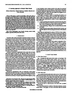
The project lasts four years and it consists of a series of increasing difficult stages. For the Reconfigurable Interactive Manufacturing Cell challenge, five teams have been funded to carry out their projects. In a first phase the objectives were common: all the teams had to perform the same industry relevant task, i.e. automatic assembly a car door module [10]. During next phases each team had to propose and carry out its own project in order to address and solve a need of one or more end users. Our team’s (ITRXCell) end user is ICPE, a Romanian factory producing electrical motors. They need a solution for the development of an automatic electric motor coil winding and assembling. This goal will be gradually reached passing through several demonstrative phases as is shown in Fig. 1. The task complexity will increase from phase to phase, until reaching the desired goal in the last phase. This final stage will test the procedure directly in ICPE facility in a realistic production environment.
Fig. 1. Operation sequence.
1.2. Market impact Our team’s project aims to increase the competitiveness in the European electric vehicles and motors manufacturing. Automation is already applied at different levels in this field, nevertheless it is facing strong competition from Countries with low labor cost. Increasing process efficiency would strengthen a very critical sector for Europe, as it is expected to garner $22.32 billion by 2022, registering a CAGR of 3.7% during the forecast period 2016-2022 [11]. Once finished, this project will help European electrical machine manufacturers to face the competition of Far East companies by introducing a flexible process able to handle different motor technologies, types and sizes while reducing hand-made work, setup time and costs. Thanks to its flexibility, the process can easily adapt to new developed motors, without the need of expensive and time-consuming changing in the layout. Particularly, the removal of auxiliary special wire guides implies a reduction of setup times of the winding machine by 50%. The robotic-based system does not require any machining of new fittings for every new production batch. This will lead to an additional reduction of setup costs by 70%, mainly in terms of effort. The number of defected cores is expected to decrease from 0.5% obtained with manual production to 0.05%. This will further decrease the costs. On average, the complete realization of an electric motor will require a few hours, while up to now it takes a day. Furthermore, the slot fill ratio can be increased, reducing the waste of copper wire. This will result in the production of more performing motors, and the implementation of a greener production process. The remainder of the paper is structured as follows. Section 2 describes the system structure and the task to carry out. Section 3 illustrates the methodologies used in the different phases. Section 4 shows the obtained results, while Section 5 summarizes the work and the results obtained. 2. Task and System description The EuRoC project is divided in phases: Freestyle, Showcase, and Pilot. Each phase is related to a task with specific objectives and metrics to achieve, eventually related one to each other. The first task-oriented phase is the Freestyle and the work reported in this paper has been carried out during such period. In this phase, we focused on developing a solid learning system and a reliable human-robot interface. Indeed, the Freestyle objectives were agreed in order to put the basis of the following Showcase and Pilot rounds. The same approach will be used during the Showcase to wind up the stator coils of an electric machine and during Pilot to perform the winding directly on the stator. The key robot action is the winding motion around a fixed point as an initial step towards the final goal to wind the coil of a real electric motor. In the Freestyle activities, the robot had to learn an arbitrary path. The team
4
Author name / Procedia Manufacturing 00 (2017) 000–000
is highly skilled in learning systems and this expertise has been exploited to teach the robot how to unroll a wire following a specific path in order to pass a wire through a peg grid composing different possible routes, as shown by an operator. The trajectory has been decided by a person not knowing the system to demonstrate the consistency of the approach used. The operator taught the selected path moving a tool in a natural manner to deploy the wire through a pin table, for a relatively low number of demonstrations. The user guided the copper wire through the pole grid using an ad-hoc designed tool maintaining the wire constantly stretched, and preventing the possibility of knotting. In order to select a pole to pass through, the operator had to roll up the wire twice around each choice. The system recorded the covered trajectories by using a camera network composed by both 2D and 3D cameras. A 6 DoF robot manipulator, equipped with the same custom wire deployment system, had to replicate the motion of the operator and unroll a wire along the same path taught by them. The result is considered correct if the robot is able to replicate the pole sequnce in the exact same order selected by the operator. Both the operator and the robot will start from a fixed position. The camera network system had also the capability to monitor the workspace by detecting and tracking humans. In this phase, the robot motion stopped as soon as a human being has been detected in a danger zone around the robot by the cameras, as a first step of a more advanced safely controlled environment. Moreover, the tool has to maintain the tension of the wire, while allowing the user to detach the tool for demonstrating the task and to attach it back on the robot when finished. During the Freestyle round, no sensor is integrated in the end effector, since the only aim of the robot is to copy the operator motion. More advanced features will be added starting from the Showcase round to improve the system capability to work within a certain tension range. As the robot deploys the wire, particular attention has to been kept in order to prevent the wire from getting stuck or break. To do so, it is important that the robot performs a human-like movement, choosing a smart way for moving from one pole to another, avoiding useless change of direction or turnabout. These observations have been considered by developing a learning by demonstration framework.
Fig. 2. System setup.
3. Methodology In our solution, we made Robot Learning and Inverse Kinematics work together in order to accomplish a more general and robust solution. The basic idea is to take advantage of the human capability to find a solution by simply looking at the problems, while leaving to the robotic system the hand mathematical computation. In our context, for people is very easy to find the path to follow in order to pass through a series of poles, while it is very difficult (or even useless) for them to compute the robot joint positions to guide the robot end effector along the same trajectory without interfering with the copper wire. In order to do so, the set of useful information extracted from the trajectories performed by humans has been described by using a Gaussian Mixture Model (GMM) [12], while a Gaussian Mixture regression (GMR) has been used for retrieving an unified smoothed trajectory for the robot TCP. Therefore, the learned trajectory has been translated from Task Space, in the tracking system reference frame, into robot Joint Space by means of a inverse kinematic engine.
Author name / Procedia Manufacturing 00 (2017) 000–000
5
During this work, we considered mainly three aspects in order to make the robot correctly reproduce the operator actions: 1. Detect the selected poles in the right order; 2. Find the best entrance and exit position for the pole wrapping; 3. Make the robot deploy the wire correctly. 3.1. Poles selection Starting from the trajectory extracted from the camera network system, our goal was to detect which poles the operator selected and in which order. The information at our disposal was already transformed and projected on the 2D plane, so the input data was a sequence of (x, y) coordinates of the tool position. The algorithm used was a derived from the consensus algorithm. The solution of the consensus problem is the result of the agreement among a number of processes (or agents). The result we would like to achieve were the pole selected by a person while deploying the wire. Basically, the consensus problem requires agreement among a number of agents for a single data value as well as our poles selection algorithm seeks at which poles have been visited and on which order. Some of the processes could be unreliable since the visual system has estimated them wrongly, therefore our selection algorithm should be able to confirm the information coming from a single point the trajectory by compering it with the others. In the same way, consensus protocols must be must somehow put forth their candidate values, and agree on a single consensus value. In our consensus algorithm, adapted for this particular case, we started dividing the grid in different areas belonging to the "nearest" pole without overlapping so that every pole is in the center of a square. The idea is to assign to each pole an afference area homogeneously distributed. After the grid division, we performed a sort of clustering operation, where each point is substituted with the relative pole area. Once we counted the number of points belonging to each pole, a threshold helps in recognizing the selected poles, without mistakenly choosing poles where the tools passes often without selecting them. It is worth to notice that each pole can be visited only once in a specific trajectory. Considering the visit order helps in correctly detect the poles in the right order. It is worth to notice that a preprocessing phase is needed for remove the still periods in which the tool is motionless in a fixed point. This case could alter the outcome, since it would result like many consecutive samples in the same pole area, seeming like as that pole has been selected. The poles detection algorithm is described accurately in Fig. 3.
Fig. 3. Pole selection algorithm.
6
Author name / Procedia Manufacturing 00 (2017) 000–000
Fig. 3. Trajectory grid.
3.2. Entrance and exit position estimation In order to avoid breaks of the wire or tangles it is important that the robot begin and end his winding motion in the correct place. The correct place depends mainly on the previously visited pole. For example, if the previously visited pole is above on the left with respect to the currently selected pole, the tool should come from left. After the implementation of poles selection, we only know which poles have been chosen, but we do not know anything about how to practically perform the winding. In order to do so, we tried to exploit the human knowledge and expertise. Usually, a person is capable to understand which is the best way to reach a fixed point also dealing with constraints. Accordingly, we can take advantage of the human operator knowledge and overcome the planning limits. Our goal is to compute the (x, y) coordinates of the start winding point and the end winding point. These coordinates are computed using a probabilistic framework. We used the start and the end winding point coordinates recorded from many winding tests performed by many different operators. The human expertise and knowledge give us the best way to overcome this critical issue in a probabilistic way. Furthermore, using many experiments performed by different subjects brings generality into the system, since every person could think to a different, although correct solution. The use of several executions allows the achievement of a generalized solution, which takes into account the intrinsic variability in the tasks. We obtained such results by using a Robot Learning by Demonstration paradigm, able to build a robust model of the coordinates starting from a limited number of demonstrations. Another vantage of this solution is that it could be used also by unskilled operators, since no further information or training phases are needed. The interesting coordinates have been selected from the operators’ recorded tool trajectory. The selection has been made empirically since there is no need of great precision, in fact it could lead to overfitting. Gaussian Mixture Model (GMM) [12] has been used as probabilistic framework to predict the (x, y) coordinates. GMM is a parametric probability density function represented as a weighted sum of K Gaussian components which best approximate the input dataset. An advantage of using GMM is the few parameters needed to represent the whole model (i.e. the mean, the covariance and the prior probability of every Gaussian component), resulting in a lightweight representation of the movement. In order to build the probabilistic model we introduced two fictitious poles in the system: pole -1 and pole +∞. The first one represents the robot’s starting point, while the second one represents the final goal, both outside the pole grid. The collected information are sufficient in order to allow a mapping of every possible combination of poles, profiting by the grid symmetry.
Author name / Procedia Manufacturing 00 (2017) 000–000
7
Considering data collected from S subjects, each of them completed the task T times and for each task he chose P different poles. The total number of data sample is N = S*T*(P+1). A single data in input at the framework ζj , 1 ≤ j ≤ N is described in Eq. 1.
j
{ w , h , w , h , x , y , x , y }
with:
8
(1)
h , w respectively width and high position of the previous pole; w , h respectively width and high position of the current pole; x , y respectively x and y coordinates of the exit position from the previous pole; x , y respectively x and y coordinates of the entrance position from the current pole.
The Expectation Maximization (EM) algorithm [13] has been used to optimize the parameters of the GMM by maintaining a monotone increasing likelihood during the local search of the maximum on the data. This approach enables an autonomous extraction of exit and entrance positions while still maintaining an appropriate generalization. Finally, the resulting probability density function is computed: p
K
j
k N j ; k , k
(2)
k 1
with:
k prior probabilities; N j ; k , k Gaussian distribution defined by k and k , respectively mean vector and covariance
matrix of the k-th distribution. The number of Gaussian components used in the model has been estimated empirically, showing good results with k = 10. The Gaussian Mixture Regression (GMR) [9] provided smooth and generalized exit and entering points for the considered poles starting from the GMM. Every exit and entering points and their covariance are estimated from the known visited poles using Equation 3 and 4.
K
{ ˆ x , ˆ y , ˆ x , ˆ y } E { x , y , x , y } | {
, h , w , h} w
k
{ ˆ x , ˆ y , ˆ x , ˆ y } k
(3)
k 1
ˆ
s
K
Cov { x , y , x , y } | {
, h , w , h} w
k 1
with:
k
ˆ
(4)
{ ˆ x , ˆ y , ˆ x , ˆ y }, k
k , the weight of the kth Gaussian component through the mixture;
{ ˆ x , ˆ y , ˆ x , ˆ y } , the conditional expectation of { x , y , x , y } given {
ˆ
{ ˆ x , ˆ y , ˆ x , ˆ y }, k
w
, h , w , h} ;
, the conditional covariance of { x , y , x , y } given { w , h , w , h } .
The generalized form of the motions required only weights, means and covariances of the Gaussian components calculated through the EM algorithm.
8
Author name / Procedia Manufacturing 00 (2017) 000–000
3.3. Robot movement Once the preprocessing phase have been completed and we have obtained the selected poles, the entrance coordinates and exit coordinates, in the right order. We had the complete information needed in order to make the robot repeat the operator task by using the inverse kinematics. We used Trac-IK [14] as inverse kinematic motor. The planner is RTT connect [15] from the OMPL library [16]. The planner includes an obstacle avoidance algorithm, in order to avoid the poles. We used MoveIt [17] as interface for planning and visualization in a virtual environment. After winding around every pole, the end effector is lifted a few millimeters, in order to avoid the wire from getting stuck. With our solution, once completed the preprocessing phase everything is handled autonomously from the robot inverse kinematics. 4. Results Since the project is structured as a challenge, we had to obtain the correct result in the shortest time in order to gain a good score. In the final test, a person showed 5 arbitrary paths previously selected from an external subject by moving the end effector in a 25 peg grid for a maximum time of 1 minute. No special marker or material has been placed on the person or on the tool. The system recorded the covered trajectories by using only the camera network system. An automatic tool has been developed to extract useful data from videos with almost no human intervention. A very complex and robust user interface has been implemented. Metric I measured the mean time needed to compute the information provided by the camera network system after the demonstration stops. The robot learned each path and passed a wire through the pegs composing the trajectory. Learning frameworks are usually based on probabilistic models built from a series of previous demonstrations called training set. An initial training set of 40 examples has been used as a basis to compute the robot trajectory. Anyway, it could not cover all possible paths, in those cases the model needs to be updated. Moreover, the operator should be able to check the validity of a novel demonstration as soon as possible. Metric II measured the mean time needed to update the model. Finally, the user should perform a low number of demonstrations to obtain the desired robot motion. Metric III measured the mean number of examples needed to learn a selected path in addition to the initial demonstration. Targets for each metric have been selected by looking at expectation of our industrial partner and taking into account the state of the art in the field. The time needed to compute the data recorded by the camera network was in mean 56.24s. We were able to provide an updated model starting only by the initial model and the data acquired during last demonstration in 2.20s. Nevertheless, the initial model was sufficient in order to compute the correct path during all the 5 different paths, resulting in 0 additional demonstrations. The system guaranteed high success rate, high responsiveness and low effort for humans. In fact, even in the worst cases, we over performed the targets by obtaining 58.21s, 2.21s, and 0 additional demonstrations respectively for Metric I, II, and III. 5. Conclusions In this paper, we presented a Robot Learning framework able to acquire information from a human demonstrations by using only a camera network system. The framework has been paired to an Inverse Kinematics engine in order to make the robot deploy a wire along a grid of poles following the same pole sequence as the human operator. We measured a set of metric in order to validate our system in accordance with the requests of a real industrial partner. We are going to use this system as a basis for the industrial winding of coils for electrical motors to be used in the automotive market.
References [1] Lasi, H., Fettke, P., Kemper, H. G., Feld, T., & Hoffmann, M. (2014). Industry 4.0. Business & Information Systems Engineering, 6(4), 239. [2] Siciliano, B., Caccavale, F., Zwicker, E., Achtelik, M., Mansard, N., Borst, C., ... & Bischoff, R. (2014, June). Euroc-the challenge initiative for european robotics. In ISR/Robotik 2014; 41st International Symposium on Robotics; Proceedings of (pp. 1-7). VDE.
Author name / Procedia Manufacturing 00 (2017) 000–000
9
[3] Hägele, M., Nilsson, K., Pires, J. N., & Bischoff, R. (2016). Industrial robotics. In Springer handbook of robotics (pp. 1385-1422). Springer International Publishing. [4] Billard, A., Calinon, S., Dillmann, R., & Schaal, S. (2008). Robot programming by demonstration. In Springer handbook of robotics (pp. 13711394). Springer Berlin Heidelberg. [5] Dillmann, R. (2004). Teaching and learning of robot tasks via observation of human performance. Robotics and Autonomous Systems, 47(2), 109-116. [6] Myers, D. R., Pritchard, M. J., & Brown, M. D. (2001). Automated programming of an industrial robot through teach-by showing. In Robotics and Automation, 2001. Proceedings 2001 ICRA. IEEE International Conference on (Vol. 4, pp. 4078-4083). IEEE. [7] Baroglio, C., Giordana, A., Piola, R., Kaiser, M., & Nuttin, M. (1996). Learning controllers for industrial robots. Machine learning, 23(2-3), 221-249. [8] Neto, P., Norberto Pires, J., & Paulo Moreira, A. (2010). High-level programming and control for industrial robotics: using a hand-held accelerometer-based input device for gesture and posture recognition. Industrial Robot: An International Journal, 37(2), 137-147. [9] Knight, W. This Factory Robot Learns a New Job Overnight. On MIT Technological review. https://www.technologyreview.com/s/601045/thisfactory-robot-learns-a-new-job-overnight/ (March 2016) [10] Michieletto, S., Stival, F., Castelli, F., & Pagello, E. (2016, June). Teaching Door Assembly Tasks in Uncertain Environment. In ISR 2016: 47st International Symposium on Robotics; Proceedings of (pp. 1-7). VDE. [11] Pal, S. Europe Electric Motor Market by Output Power (Integral Horsepower (IHP), Fractional Horsepower (FHP) Output), by Application (Industrial Machinery, Motor Vehicles, Heating Ventilating and Cooling (HVAC) Equipment, Aerospace & Transportation, Household Appliances, Commercial Applications) - Opportunity Analysis and Industry Forecast, 2014 – 2022. On Engineering, Equipment and Machinery. https://www.alliedmarketresearch.com/europe-electric-motor-market (Mar 2016). [12] Calinon, S., Guenter, F., & Billard, A. (2007). On learning, representing, and generalizing a task in a humanoid robot. IEEE Transactions on Systems, Man, and Cybernetics, Part B (Cybernetics), 37(2), 286-298. [13] Dempster, A. P., Laird, N. M., & Rubin, D. B. (1977). Maximum likelihood from incomplete data via the EM algorithm. Journal of the royal statistical society. Series B (methodological), 1-38. [14] Beeson, P., & Ames, B. (2015, November). TRAC-IK: An open-source library for improved solving of generic inverse kinematics. In Humanoid Robots (Humanoids), 2015 IEEE-RAS 15th International Conference on (pp. 928-935). IEEE. [15] Kuffner, J. J., & LaValle, S. M. (2000). RRT-connect: An efficient approach to single-query path planning. In Robotics and Automation, 2000. Proceedings. ICRA'00. IEEE International Conference on (Vol. 2, pp. 995-1001). IEEE. [16] Sucan, I. A., Moll, M., & Kavraki, L. E. (2012). The open motion planning library. IEEE Robotics & Automation Magazine, 19(4), 72-82. [17] Chitta, S., Sucan, I., & Cousins, S. (2012). Ros topics. IEEE robotics and automation magazine, 19(1), 18-19.