Available online on Wiley-Blackwell's website: http://dx.doi.org/10.1002/rob. ... Such a small number of constraints allows an easy integration into the AWARE ...
A Distributed Architecture for a Robotic Platform with Aerial Sensor Transportation and Self-Deployment Capabilities Ivan Maza, Fernando Caballero, Jesus Capitan, J.R. Martinez-de-Dios and Anibal Ollero∗ Robotics, Vision and Control Group Universidad de Sevilla 41092 Seville, Spain {imaza,fcaballero}@us.es,{jescap,jdedios,aollero}@cartuja.us.es
Abstract This paper presents the architecture developed in the framework of the AWARE project for the autonomous distributed cooperation between unmanned aerial vehicles (UAVs), wireless sensor/actuator networks and ground camera networks. One of the main goals was the demonstration of useful actuation capabilities involving multiple ground and aerial robots in the context of civil applications. A novel characteristic is the demonstration in field experiments of the transportation and deployment of the same load with single/multiple autonomous aerial vehicles. The architecture is endowed with different modules that solve the usual problems that arise during the execution of multi-purpose missions, such as task allocation, conflict resolution, task decomposition and sensor data fusion. The approach had to satisfy two main requirements: robustness for the operation in disaster management scenarios and easy integration of different autonomous vehicles. The former specification led to a distributed design and the latter was tackled by imposing several requirements on the execution capabilities of the vehicles to be integrated in the platform. The full approach was validated in field experiments with different autonomous helicopters ∗ Also
with the Center for Advanced Aerospace Technologies (CATEC), Parque Tecnol´ ogico y Aeron´ autico de Andaluc´ıa, C. Wilbur y Orville Wright 17-19-21, 41309, La Rinconada, Spain.
This is a preprint of an article published in Journal of Field Robotics: A Distributed Architecture for a Robotic Platform with Aerial Sensor Transportation and Self-Deployment Capabilities, Ivan Maza, Fernando Caballero, Jesus Capitan, J.R. Martinez-de-Dios and Anibal Ollero, Journal of Field Robotics, Volume 28, Issue 3, pages 303-328, Copyright 2011 Wiley-Blackwell). Available online on Wiley-Blackwell’s website: http://dx.doi.org/10.1002/rob.20383
equipped with heterogeneous devices on-board, such as visual/infrared cameras and instruments to transport loads and to deploy sensors. Four different missions are presented in this paper: sensor deployment and fire confirmation with UAVs, surveillance with multiple UAVs, tracking of firemen with ground and aerial sensors/cameras, and load transportation with multiple UAVs.
1
Introduction
The work presented in this paper has been developed within the framework of the AWARE Project1 funded by the European Commission (June 2006 – September 2009). The researchers from the University of Seville led a consortium comprising five Universities (Technical University of Berlin and Universities of Seville, Bonn, Stuttgart and Twente) and three companies (Selex Sensors and Airborne Systems, Flying-Cam and the Iturri Group) from five European countries. The general objective of the project was the design, development and demonstration of a platform composed of heterogeneous systems that are able to operate in a distributed manner in disaster management scenarios without pre-existing (or with damaged) infrastructure. Thus, the platform should comprise self-deployment capabilities, i.e. autonomous transportation and deployment of different types of loads (small sensors, cameras, communication equipment, etc.) by means of one or several helicopters. The systems integrated in the platform included aerial robots, wireless sensor networks, ground-fixed cameras and ground vehicles with actuation capabilities. There are several projects dealing with the integration of robots and wireless sensor networks. Many of them have addressed the development of techniques (Moore et al., 2004; Batalin et al., 2004; Yao and Gupta, 2010; Ferrari and Foderaro, 2010) for the guidance of mobile robots based on the sensorial stimuli provided by the wireless sensors. The use of mobile nodes has an impact on the quality of service of the sensor network and it has been shown how quality metrics are related to the motion strategies of the mobile nodes (Bisnik et al., 2007). Coverage, exploration and deployment of sensor nodes has also been proposed (Batalin and Sukhatme, 2007). The integration of aerial robots and ground wireless sensor networks in field experiments has been also addressed in the last years. Autonomous helicopters have been proposed for the deployment and repair of a wireless sensor network (Corke et al., 2004b; Corke et al., 2004a). The ANSER Project (Sukkarieh et al., 2003) tackled decentralized data fusion and SLAM with a team of autonomous aerial 1 http://www.aware-project.net
This is a preprint of an article published in Journal of Field Robotics: A Distributed Architecture for a Robotic Platform with Aerial Sensor Transportation and Self-Deployment Capabilities, Ivan Maza, Fernando Caballero, Jesus Capitan, J.R. Martinez-de-Dios and Anibal Ollero, Journal of Field Robotics, Volume 28, Issue 3, pages 303-328, Copyright 2011 Wiley-Blackwell). Available online on Wiley-Blackwell’s website: http://dx.doi.org/10.1002/rob.20383
and ground sensors. Finally, the NAMOS project at USC also integrates marine robots and wireless sensor networks (Das and Sukhatme, 2009). On the other hand, there are also relevant projects dealing with multi-robot teams in emergency situations such as the EMBER CMU project, whose goal is to assist first responders by providing tracking information and the ability for coordination. In EMBER, range information is used for searching and tracking mobile targets with multiple robots (Hollinger et al., 2009). Multi-agent (combined ground and air) tasking and cooperative target localization has also been demonstrated recently (Hsieh et al., 2007). Although not in the area of field robotics, there is more recent work on multi-target tracking (ground vehicles) with a micro-UAV (He et al., 2010). However, there are very few projects involving the demonstration in field experiments of actuation capabilities by a team of aerial robots integrated with wireless sensor networks. This paper presents the architecture developed within the framework of the AWARE Project for autonomous distributed cooperation between unmanned aerial vehicles (UAVs), wireless sensor/actuator networks and ground camera networks. One of the main goals of the project was the demonstration of useful actuation capabilities involving multiple ground and aerial robots in the context of civil applications. The transportation and deployment of the same load with single/multiple autonomous aerial vehicles was demonstrated in field experiments. The approach adopted is partially derived from two main requirements of the project: easy integration of different autonomous vehicles and robustness for the operation in disaster management scenarios. The former specification was tackled by imposing a number of requirements on the execution capabilities of the vehicles to be integrated in the platform. Basically, those vehicles should be able to move to a given location and activate their onboard instrument when required. Such a small number of constraints allows an easy integration into the AWARE architecture of autonomous vehicles from different manufacturers and research groups. The latter requirement led to a distributed design that followed an “intentional” cooperation approach (Parker, 1998): Each individual executes a set of tasks (subgoals that are necessary to achieve the overall goal of the system, and that can be completed independently of other subgoals) explicitly allocated to perform a given mission in an efficient manner according to planning strategies. This approach fits well with the heterogeneity of the platform and the specifications of the project, but also has the limitation of independent subgoals: If the order of task completion is mandatory, additional explicit knowledge has to be provided to state ordering dependencies in the preconditions. It is also possible to follow a design based on This is a preprint of an article published in Journal of Field Robotics: A Distributed Architecture for a Robotic Platform with Aerial Sensor Transportation and Self-Deployment Capabilities, Ivan Maza, Fernando Caballero, Jesus Capitan, J.R. Martinez-de-Dios and Anibal Ollero, Journal of Field Robotics, Volume 28, Issue 3, pages 303-328, Copyright 2011 Wiley-Blackwell). Available online on Wiley-Blackwell’s website: http://dx.doi.org/10.1002/rob.20383
“collective” interaction, in which entities are not aware of other entities in the team, yet they do share goals, and their actions are beneficial to their teammates (Parker, 2008). Although swarm approaches have been studied for surveillance/tracking tasks with UAVs (Legras et al., 2008), this option was not adopted because it did not fit well with the requirements of the end-users. The distributed approach involves well-known challenging issues such as distributed task allocation and conflict resolution for the UAVs, and distributed estimation based on multiple disparate sensors. A domainindependent taxonomy of multi-robot task allocation problems has been presented previously (Gerkey and Matari´c, 2004). A popular approach in recent years to solve this problem in a distributed manner is the application of market-based negotiation rules. A common implementation of those rules (Botelho and Alami, 1999; Dias and Stentz, 2002; Gerkey and Matari´c, 2002) is based on the Contract Net Protocol (CNP) (Smith, 1980). This market-based approach has also been adopted in our platform. On the other hand, a decentralized data fusion framework (Capitan et al., 2009) is used to integrate the information from disparate sensors in order to track the position and velocity of moving objects (such as persons) or to localize potential alarms (such as fires). The information fused is gathered by a network of heterogeneous sensors, including visual or infrared cameras, static wireless sensor networks and sensors transported by people. The full approach was validated in field experiments with different autonomous helicopters equipped with heterogeneous devices on-board such as infrared cameras, instruments to transport and deploy objects or visual cameras. Four different missions are presented in this paper: sensor deployment and fire confirmation with UAVs, surveillance with multiple UAVs, tracking of firemen with ground and aerial sensors/cameras, and load transportation with multiple UAVs. A previous paper (Maza et al., 2010) described the preliminary experiments of 2008 in the framework of sensor network repair and load transportation using the autonomous helicopters of the AWARE platform. The paper is structured as follows. Firstly, the distributed architecture is presented in Section 2. The setup for the experiments carried out is presented in Section 3, followed by a detailed description of the field experiments used for the validation in Section 4. Finally, the lessons learned from the experiments and the conclusions close the paper.
This is a preprint of an article published in Journal of Field Robotics: A Distributed Architecture for a Robotic Platform with Aerial Sensor Transportation and Self-Deployment Capabilities, Ivan Maza, Fernando Caballero, Jesus Capitan, J.R. Martinez-de-Dios and Anibal Ollero, Journal of Field Robotics, Volume 28, Issue 3, pages 303-328, Copyright 2011 Wiley-Blackwell). Available online on Wiley-Blackwell’s website: http://dx.doi.org/10.1002/rob.20383
2
Distributed Architecture of the Platform
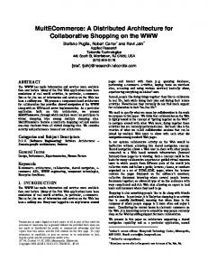
A global mission for the AWARE platform is specified by the operator using the Human Machine Interface (HMI) software application. Each mission M consists of a set of tasks (possibly ordered) that must be executed by the platform. The distribution of the tasks among the different UAVs (task allocation process) could be carried out manually by the user or may be autonomously performed in a distributed manner. The latter might be mandatory in situations where large numbers of UAVs have to interact, where direct communication with a central station is not possible, or where the local dynamics of the situation requires timely reaction of the UAVs involved. The main objective in the design of the multi-UAV architecture was to impose few requirements on the execution capabilities of the autonomous vehicles to be integrated in the platform. Basically, these vehicles should be able to move to a given location and activate their on-board instrument when required. Thus UAVs from different manufacturers and research groups can be easily integrated to the architecture. The global picture of the AWARE distributed UAV architecture is shown in Figure 1. In each UAV, there are two main layers: the On-board Deliberative Layer (ODL) and the proprietary Executive Layer (EL). The former deals with the high-level distributed decision-making, whereas the latter is in charge of the execution of the tasks. In the interface between the two layers the ODL sends elementary task requests and receives the execution state of each elementary task and the UAV state. Distributed decision-making requires interactions among the ODLs of different UAVs. Finally, the HMI software allows the user to specify the missions and tasks to be executed by the platform, and also to monitor the execution state of the tasks and the status of the different UAVs. The different modules shown in the ODL support the distributed decision-making process involving cooperation and coordination. Further details about the operation of each ODL module can be found in the next subsections. Each module was implemented in C++ to test the whole platform in real missions (see Section 4), but the research work has been mainly focused on the following modules:
• Task refining toolbox (Section 2.4): Once a task is received by the UAV, this module decomposes it into elementary tasks (if applicable) and also computes the associated execution costs. • Task allocation manager (Section 2.5): Taking into account the costs computed by the previous module and using the services of the plan builder (see Section 2.3), these modules negotiate in a distributed manner in order to allocate the different tasks. This is a preprint of an article published in Journal of Field Robotics: A Distributed Architecture for a Robotic Platform with Aerial Sensor Transportation and Self-Deployment Capabilities, Ivan Maza, Fernando Caballero, Jesus Capitan, J.R. Martinez-de-Dios and Anibal Ollero, Journal of Field Robotics, Volume 28, Issue 3, pages 303-328, Copyright 2011 Wiley-Blackwell). Available online on Wiley-Blackwell’s website: http://dx.doi.org/10.1002/rob.20383
UAV Architecture
Perception System
Task allocation
Plan merging Task refining toolbox
UAV state
Elem task request Proprietary supervisor
Task status
Missions Plan builder / optimizer
UAV controller
Negotiation messages
Planned tasks
Task status
Task request
4D trajectories
Task manager
Elem task status Synch info Executive simulator
Synch query
AWARE HMI
Executive Layer
Proprietary GUI interface (supervision and management)
On-board Deliberative Layer (ODL)
On-board Deliberative Layer
Executive Layer (EL)
Other UAVs Task status
Synch manager
Figure 1: Modules and interactions in the architecture adopted for each UAV of the platform, which is based on two main layers: the On-board Deliberative Layer (ODL) and the proprietary Executive Layer (EL). The modules and information interchanged are represented by boxes and ellipses respectively.
This is a preprint of an article published in Journal of Field Robotics: A Distributed Architecture for a Robotic Platform with Aerial Sensor Transportation and Self-Deployment Capabilities, Ivan Maza, Fernando Caballero, Jesus Capitan, J.R. Martinez-de-Dios and Anibal Ollero, Journal of Field Robotics, Volume 28, Issue 3, pages 303-328, Copyright 2011 Wiley-Blackwell). Available online on Wiley-Blackwell’s website: http://dx.doi.org/10.1002/rob.20383
• Plan merging module (Section 2.6): Before the execution of the elementary tasks in the plan, this module negotiates in order to guarantee that the path to be traversed by each UAV is clear of other UAVs. • Perception system (Section 2.7): This system is in charge of gathering information from the sensors and running the decentralized data fusion engine.
Once each UAV has built its own plan, the task and synchronization managers deal with changes in the state of the tasks, synchronization in the execution with other UAVs and the interface with its executive layer. Since each UAV has its own plan, several kinds of interaction during task achievement may occur:
• Coordination, mainly for sharing the airspace while avoiding conflicts. Local interactions among UAVs that plan to share the same region of space are required to solve this problem (see Section 2.6). • Cooperation: includes coordination, but implies the existence of complementary roles to achieve a global common goal. Examples in the AWARE platform are the transportation of an object by several autonomous helicopters (if the weight exceeds the lifting capabilities of a single helicopter) (Maza et al., 2010), or the surveillance of the same object from different viewpoints. • Redundancy and opportunism are related to the detection of identical tasks that are achieved by several components because their individual plans require these tasks. Detecting redundant tasks, such as taking the same images, enables such tasks to be suppressed from all the cameras except one and sharing the result, thus optimizing the global mission. On the other hand, it is also possible to use redundancy to improve the reliability of the whole system in case of a partial failure.
This is the general picture of the distributed approach adopted for the multi-UAV platform. In the next subsection the task model adopted in the interface among ODLs and between each ODL and its EL is summarized.
2.1
Task Model
Let us consider a mission M specified by the AWARE platform user. This mission is decomposed (autonomously or manually) into a set of partially ordered tasks T . Let us define a task with unique identifier k and type λ allocated to the i-th UAV as τik = (λ,− Ω, Ω+ , ε, Π), where
−
Ω and Ω+ are, respectively, the
set of preconditions and postconditions of the task, and ε is the state associated with the task evolution This is a preprint of an article published in Journal of Field Robotics: A Distributed Architecture for a Robotic Platform with Aerial Sensor Transportation and Self-Deployment Capabilities, Ivan Maza, Fernando Caballero, Jesus Capitan, J.R. Martinez-de-Dios and Anibal Ollero, Journal of Field Robotics, Volume 28, Issue 3, pages 303-328, Copyright 2011 Wiley-Blackwell). Available online on Wiley-Blackwell’s website: http://dx.doi.org/10.1002/rob.20383
Table 1: Possible states considered in the status evolution of a task τik . State (ε) Description EMPTY No task SCHEDULED The task is waiting to be executed RUNNING The task is in execution CHECKING The task is being checked against inconsistencies and static obstacles MERGING The task is in the plan merging process to avoid conflicts with other UAVs’ trajectories ABORTING The task is in process to be aborted. If it is finally aborted, the status will change to ABORTED, and otherwise will return to RUNNING ABORTED The task has been aborted (the human operator has aborted it or the UAV was not able to accomplish the task properly) ENDED The task has been accomplished properly
(see Table 1). The list in Table 2 shows the type of tasks (λ) at the ODL level considered in the AWARE platform. Finally, Π = {π 1 , π 2 , . . . , π m } is the set of m parameters that characterizes each task. The ODL processes the tasks received and generates simpler tasks, called elementary tasks, that are finally sent to the executive layer for its immediate execution without further processing. Let us define an ˆ allocated to the i-th UAV as τˆk = (λ, ˆ Π, ˆ εˆ), where elementary task with unique identifier k and type λ i ˆ ˆ = {ˆ Π π1 , π ˆ2, . . . , π ˆm } is the set of m ˆ parameters that characterizes the elementary task and εˆ is the state
associated with the elementary task evolution. It should be mentioned that RUNNING and ENDED are the only states considered for the elementary tasks, decreasing the required complexity of the executive layer software. The vehicles to be integrated in the AWARE platform should be able to receive elementary tasks, execute them and report their associated execution states. A small set of elementary tasks have been considered in order to allow the integration of a broader number of vehicles from different manufacturers and research groups. Basically, those vehicles should be able to move to a given location and activate their on-board instrument when required. Additionally, autonomous take-off and landing capabilities are also required. Thus the elementary tasks considered represent a subset composed of the first three tasks in Table 2. A task of type GOTO can be received either by the ODL or the executive layer. In the first case the task could be further processed to avoid static obstacles for example, whereas in the latter case the task will be executed immediately. Finally, it should be mentioned that the architecture allows the execution of several tasks or elementary tasks in parallel among multiple robots. In the rest of this section, more details about the ODL modules in This is a preprint of an article published in Journal of Field Robotics: A Distributed Architecture for a Robotic Platform with Aerial Sensor Transportation and Self-Deployment Capabilities, Ivan Maza, Fernando Caballero, Jesus Capitan, J.R. Martinez-de-Dios and Anibal Ollero, Journal of Field Robotics, Volume 28, Issue 3, pages 303-328, Copyright 2011 Wiley-Blackwell). Available online on Wiley-Blackwell’s website: http://dx.doi.org/10.1002/rob.20383
Table 2: Type of tasks (λ) considered at the ODL level. Type of task (λ) Description TAKE-OFF Take off, stabilize at a default safe altitude, then switch to a safe mode, waiting for further instructions LAND The UAV starts landing procedures, lands, and is set to a ground safe mode GOTO The UAV moves from its current location to a point P GOTOLIST Go from the current location to each of the points of a waypoints list in order DEPLOY The UAV moves from its current location to a point P and activates its payload in order to deploy a device TAKE-SHOT Go from the current location to a point P and take images of a given location L. P is computed to have L in the center of the on-board camera’s field of view WAIT The UAV is set to a safe waiting mode: hover or pseudo-hover, during a given period SURV Cover a given area defined by a polygon at a certain altitude TRACK The perception system of the UAV starts to operate in tracking mode, providing (if possible) location estimations of a given object (fire, persons, etc.). The UAV moves to a location that allows the estimation to be improved HOME Return home Figure 1 are presented, starting with the task and synchronization managers whose design is linked with the task model presented above.
2.2
Task and Synchronization Managers
The task manager module receives the planned tasks from the plan builder module and sends elementary tasks to the executive, which reports the state of those tasks and the UAV itself. The synchronization manager ensures the synchronization in the execution of the tasks in the plan of the UAV, and also between tasks of different UAVs.
2.2.1
Task Manager
The task manager controls partially ordered sequences of tasks in a consistent, timely and safe manner. In each task request from the plan builder, two operations are possible:
• Dynamic task insertion: this allows a request for tasks to be inserted in the UAV’s current plan, according to the relative order specified for the newly inserted task, versus the current partial order of the tasks already scheduled. This operation allows a task to be inserted with preconditions and/or postconditions. Both event-based mechanisms can deal with events related to the evolution of the This is a preprint of an article published in Journal of Field Robotics: A Distributed Architecture for a Robotic Platform with Aerial Sensor Transportation and Self-Deployment Capabilities, Ivan Maza, Fernando Caballero, Jesus Capitan, J.R. Martinez-de-Dios and Anibal Ollero, Journal of Field Robotics, Volume 28, Issue 3, pages 303-328, Copyright 2011 Wiley-Blackwell). Available online on Wiley-Blackwell’s website: http://dx.doi.org/10.1002/rob.20383
tasks states (see Table 1), to the reception of messages, to the detection of a given event by the perception system, the elapsing of a certain time period, etc. The execution of a task starts when all its preconditions are satisfied. Preconditions can be specified either as mandatory or optional. If it is mandatory and the precondition is no longer satisfiable, then the task is aborted. In contrast, if it is optional, the precondition is considered satisfied (and hence removed from the task’s list of preconditions) if it is actually satisfied or if it becomes unsatisfiable (and in this case the task is not aborted). It is also possible to specify postconditions, i.e. conditions on the state that are met when a task is completed. • Dynamic task abortion: this mechanism allows task abortions to be requested dynamically in the current plan, while the plan is being executed. If the task is already running, then the abortion of the task is an interruption. If the task is not yet running, then the abortion is a cancellation (the task is de-scheduled). The abortion triggers a propagation mechanism, that checks which of the scheduled tasks depends on the aborted task (i.e. the tasks having a precondition expecting a state from the aborted task, such as ENDED): if the dependence is a mandatory precondition, then this task is also aborted. If it is an optional precondition, then the dependence is removed as if the precondition was satisfied, and the corresponding task is not aborted.
The management of the preconditions and postconditions is carried out together with the task synchronization module. In the interface between the two modules there is a simple protocol based on messages, which will be explained in the following paragraphs.
2.2.2
Synchronization Manager
The synchronization manager module is in charge of keeping the dependencies coherent between the different tasks in the current plan of the UAV, and also with the tasks of other UAVs. When a new task request with preconditions and/or postconditions arrives at the task manager module, it sends a message with the dependencies to the synchronization manager, which saves the information in a local database. The synchronization manager is always checking the state of the tasks in the distributed UAV system and, if there is any change, it updates the dependencies database. For instance, if a given task changes its state to ENDED and if this state is a precondition for other tasks, those preconditions are changed to satisfied. On the other hand, if all of the postconditions of a task are satisfied, another message is sent to the task manager module that will proceed with the corresponding action. This is a preprint of an article published in Journal of Field Robotics: A Distributed Architecture for a Robotic Platform with Aerial Sensor Transportation and Self-Deployment Capabilities, Ivan Maza, Fernando Caballero, Jesus Capitan, J.R. Martinez-de-Dios and Anibal Ollero, Journal of Field Robotics, Volume 28, Issue 3, pages 303-328, Copyright 2011 Wiley-Blackwell). Available online on Wiley-Blackwell’s website: http://dx.doi.org/10.1002/rob.20383
Before requesting an elementary task at the executive layer, the task manager sends a query message with the sequence number of the task to the synchronization manager. The satisfiability is checked and the answer is sent back. If all the preconditions are not satisfied the task manager will ask again periodically.
2.3
Plan Builder / Optimizer
An offline planner is used before the execution of each mission. If there are groups of motion tasks without preconditions and/or postconditions in the plan, an online planner orders them in order to minimize their execution cost. Both planners are briefly described in the following:
• Offline planning: prior to its execution, the AWARE platform user can plan the mission to tune its parameters and check its feasibility using the EUROPA framework developed at NASA’s Ames Research Center. EUROPA (Extensible Universal Remote Operations Planning Architecture) is a class library and tool set for building planners (and/or schedulers) within a Constraint-based Temporal Planning paradigm and it is typically embedded in a host application. Constraint-based Temporal Planning (and Scheduling) is a paradigm of planning based on an explicit notion of time and a deep commitment to a constraint-based formulation of planning problems. This paradigm has been successfully applied in a wide range of practical planning problems and has a legacy of success in NASA applications. • Online planning: this is based on a plan builder/optimizer module developed in the framework of the project. This module generates partial plans P by ordering the groups of motion tasks without preconditions and/or postconditions allocated to the UAV. Basically it is used to schedule waypoint traversal. Let us consider the i-th UAV with a set of nm motion tasks to be executed. The planner computes the order of the tasks {τik |k = 1, 2, . . . , nm } that minimizes the execution cost
Ci =
n∑ m −1
ck,k+1 , i
(1)
k=1
where ck,k+1 is the motion cost between the locations associated with tasks τik and τik+1 . This i problem is an instance of the Travelling Salesmen Problem, which is NP-hard. The simplest exact algorithm to solve it is based on a brute force search that tries all the ordered combinations of tasks. This is a preprint of an article published in Journal of Field Robotics: A Distributed Architecture for a Robotic Platform with Aerial Sensor Transportation and Self-Deployment Capabilities, Ivan Maza, Fernando Caballero, Jesus Capitan, J.R. Martinez-de-Dios and Anibal Ollero, Journal of Field Robotics, Volume 28, Issue 3, pages 303-328, Copyright 2011 Wiley-Blackwell). Available online on Wiley-Blackwell’s website: http://dx.doi.org/10.1002/rob.20383
The running time for this approach lies within a polynomial factor of O((nm − 1)!), so this solution is only feasible when a small number of tasks are allocated to the UAVs, which is the case in most of the AWARE platform missions. However, if the user delegates the allocation process to the ODLs, each UAV will have to run the planning algorithm many times during the autonomous negotiation with other UAVs. Thus, another algorithm with a lower computational cost is required: Each time a new task is received, the plan builder checks the insertion of the new task in all the possible and feasible locations in the current plan and chooses the insertion point with lowest cost for the plan.
2.4
Task Refining Toolbox
This module groups several tools, including mission and task decomposition services, to other modules of the architecture, execution cost estimations and static obstacle avoidance. It can interact with the perception subsystem module on-board to retrieve information about the environment. The methods implemented for task decomposition in the context of missions involving monitoring, deployment and surveillance are described in Section 4. Regarding the notation, if a task τik is decomposed into Ne elementary tasks the following representation will be used
τik → {1 τˆik ,2 τˆik , . . . ,Ne τˆik }
2.5
(2)
Distributed Task Allocation
An important issue in autonomous coordination is the multi-robot task allocation (MRTA) problem, which has received significant attention in the last decade. Different approaches have been used to solve this problem: centralized (Brumitt and Stentz, 1998; Caloud et al., 1990), hybrid (Dias and Stentz, 2002; Ko et al., 2003) and distributed (Gerkey and Matari´c, 2000; Werger and Matari´c, 2000). Within the distributed approaches, the market-based approach (Dias et al., 2006) has become very popular since it offers a good compromise between communication requirements and the quality of the solution. This can be considered as an intermediate solution between centralized and completely distributed since it makes decisions based on inter-agent communications transmitted at different time instants. This type of algorithm is more fault-tolerant than a centralized option, and can obtain more efficient solutions than applying a completely distributed approach. Thus, this approach has been adopted in our platform. This is a preprint of an article published in Journal of Field Robotics: A Distributed Architecture for a Robotic Platform with Aerial Sensor Transportation and Self-Deployment Capabilities, Ivan Maza, Fernando Caballero, Jesus Capitan, J.R. Martinez-de-Dios and Anibal Ollero, Journal of Field Robotics, Volume 28, Issue 3, pages 303-328, Copyright 2011 Wiley-Blackwell). Available online on Wiley-Blackwell’s website: http://dx.doi.org/10.1002/rob.20383
Several market-based algorithms were developed during the project (Viguria et al., 2007; Viguria et al., 2008) and these were based on previous work in the area (Dias and Stentz, 2002; Gerkey and Matari´c, 2002; Lemaire et al., 2004; Xu et al., 2006). The specified goal was to find solutions that could minimize the global cost defined as the sum of all the individual costs assuming independent tasks. Among the developed strategies, the algorithm
2
finally chosen for our platform is based on two different roles played dynamically
by the UAVs: auctioneer and bidders. In each auction there is only one auctioneer, which is the UAV that has a token. The auction is opened for a period of time during which all the bids received are considered. When the auction is finished and the task is allocated, the auctioneer passes the token to another UAV. If this happens, the auctioneer changes its role to a bidder and the UAV with the token becomes the new auctioneer. The best bid collected by the auctioneer is increased by a given percentage (usually 1%) to avoid transactions that will not significantly improve the solution. If a token is requested and no answer is received during a preprogrammed period of time, the token is assumed to be lost (due to a communication failure for instance) and a new token is generated. In the negotiation process, each UAV bids for a task with the cost of inserting this task in its local plan (marginal cost).
Let us assume that the i-th UAV has a local plan Pi (generated by the plan
builder/optimizer) with cost Ci consisting in a set of n ordered motion tasks. At this point a new task τ is received. If this task is inserted at the j-th position in the plan Pi , then a new plan Pi (τ j ) with cost Ci (τ j ) is generated. In that case, the associated marginal cost µj is given by
µj = Ci (τ j ) − Ci .
(3)
The plan builder module of each UAV computes the insertion point of the new task in its current plan. Thus, as the bid of each UAV depends on its current plan, every time the local plan changes, the negotiation continues until no bids improve the current global allocation. When the initial negotiation is over the mission execution can start, but new tasks can be announced at any moment. Therefore, the negotiation is dynamic in the sense that new tasks are also handled during the mission execution. For instance, if an error in the execution of a task is reported then the task is re-announced. Additionally, new tasks can also be generated to increase confidence in monitoring missions, for example if the uncertainty of the estimation is above a certain threshold during a programmed period. All the UAVs take part in the negotiation of these new tasks with the only restriction being that the current tasks in execution are not re-negotiated. 2 The
so-called SIT algorithm (Viguria et al., 2007) was chosen due to its better trade-off between required messages and proximity to the optimal solutions.
This is a preprint of an article published in Journal of Field Robotics: A Distributed Architecture for a Robotic Platform with Aerial Sensor Transportation and Self-Deployment Capabilities, Ivan Maza, Fernando Caballero, Jesus Capitan, J.R. Martinez-de-Dios and Anibal Ollero, Journal of Field Robotics, Volume 28, Issue 3, pages 303-328, Copyright 2011 Wiley-Blackwell). Available online on Wiley-Blackwell’s website: http://dx.doi.org/10.1002/rob.20383
2.6
Plan Merging Process
The plan merging module has been designed to detect potential conflicts among different trajectories in order to avoid them. This module therefore has to interact with the plan builder module and also with other UAVs to interchange the different trajectories involved. One of the key aspects in the design was to impose few requirements to the proprietary vehicles to be integrated in the AWARE platform. Thus, a specification of the particular trajectory or velocity profile during the flight is not considered, and the implemented policy to avoid the inter-vehicle collisions is only based on the elementary set of tasks presented in Section 2.1. It is assumed that each UAV has a plan already defined that can be retrieved at any moment from the plan builder module. From the executive level perspective, the plan can be viewed as a list of waypoints to be visited.
2.6.1
Problem Formulation
Let us consider n UAVs in the platform with an initial state free of conflicts. For spatial conflict detection purposes, only the motion tasks in the individual plan of each UAV will be considered. As it has been mentioned above, the hovering capability of the UAVs in the AWARE platform is exploited to simplify the solution of the problem, as far as the only motions that should be checked against conflicts are the transitions between waypoints. From the elementary tasks presented in Section 2.1, a set of two states Si = {s1i , s2i } is considered taking into account the motion of the i-th UAV:
• State s1i : stationary flight around a waypoint P . The UAV can be either waiting for a new motion task or waiting until the path to the next waypoint is clear. • State s2i : flying between waypoints P k and P k+1 . The straight path ∆ki between those waypoints is considered as the reference trajectory for the i-th UAV.
Hence, the conflicts can arise only in the transitions from states s1i to s2i . Thus, before proceeding to state s2i , the i-th UAV has to check two types of potential conflicts with the j-th UAV depending on its current state sj :
• Type A (if sj = s1j ): potential conflict between the next path ∆ki and the current position of the j-th UAV. This is a preprint of an article published in Journal of Field Robotics: A Distributed Architecture for a Robotic Platform with Aerial Sensor Transportation and Self-Deployment Capabilities, Ivan Maza, Fernando Caballero, Jesus Capitan, J.R. Martinez-de-Dios and Anibal Ollero, Journal of Field Robotics, Volume 28, Issue 3, pages 303-328, Copyright 2011 Wiley-Blackwell). Available online on Wiley-Blackwell’s website: http://dx.doi.org/10.1002/rob.20383
• Type B (if sj = s2j ): potential conflict between the next path ∆ki and the path ∆lj currently being followed by the j-th UAV.
Then, the problem to be solved can be formulated as: avoid conflicts of types A and B in the transitions s1i → s2i ∀i = 1, . . . , n. The distributed algorithm developed to solve it and ensure the clearance of the paths is described in the following subsection.
2.6.2
Distributed Method for Conflict Resolution
The basic idea of the distributed method proposed (Maza, 2010) is to guarantee that when an UAV is traversing a path between two consecutive waypoints, that route is clear of other UAVs. There are three transitions considered in the method implemented:
• χ1 : triggered when the current task τik changes its state to MERGING (see Table 1). • χ2 : activated when a request message is received from another UAV. • χ3 : triggered by a reply message received from another UAV.
Regarding the first transition χ1 , let us consider a motion task τik with an associated path ∆ki . Initially, the status of the task is SCHEDULED and all the preconditions for its execution are satisfied. If the i-th UAV were in a non-shared airspace, ϵk should change from SCHEDULED to RUNNING and the execution of τik should start immediately. However, as there are more UAVs in the platform sharing the airspace, an intermediate state called MERGING is considered before starting the execution of the motion task. Once τik changes its state to MERGING, it is checked if the associated path ∆ki is clear for the i-th UAV. It should be noticed that after the execution of τik , the path ∆ki is clear again and this condition must also be notified to other UAVs. On the other hand, the i-th UAV also has to manage the request and reply messages received from other UAVs (transitions χ2 and χ3 ). When a request message is received, the UAV has to check if the received path is in conflict, whereas if a reply is received a counter of positive replies is updated. The algorithms that manage the transitions χ1 , χ2 and χ3 run asynchronously. In order to check if the ∆lj path is in conflict with a path requested by the i-th UAV, and if the ∆lj path is in conflict with the i-th UAV current location, the following bounding solid has been considered for simplicity: a box of edge length 2ri centered at the GPS antenna location. Thus according to the set of states Si described This is a preprint of an article published in Journal of Field Robotics: A Distributed Architecture for a Robotic Platform with Aerial Sensor Transportation and Self-Deployment Capabilities, Ivan Maza, Fernando Caballero, Jesus Capitan, J.R. Martinez-de-Dios and Anibal Ollero, Journal of Field Robotics, Volume 28, Issue 3, pages 303-328, Copyright 2011 Wiley-Blackwell). Available online on Wiley-Blackwell’s website: http://dx.doi.org/10.1002/rob.20383
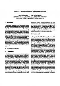
in Section 2.6.1 and the bounding box selected, there are two types of solids involved in the potential conflict detection process (see Figure 2): A box for each UAV in stationary flight and a rectangular hexahedron for each path between waypoints. Taking into account that the chosen bounding solids are convex objects, it is possible to apply the method of separating axes (Gottschalk et al., 1996), which allows one to determine whether or not two convex objects in the space are intersecting. Extensions of this method allow the handling of moving convex objects and are useful for predicting collisions of the objects and for computing the first time of contact. This approach has been adopted in the current implementation as it also allows flexibility for future extensions of this work.
2r
a) k+1
P
2r
2r
b) Pk
2r
P 2r
2r
z 2r
2r
y x
2r
Figure 2: Bounding solids adopted for each motion state of the UAV. a) Rectangular hexahedron for each path between the waypoints P k and P k+1 (state s2i ). b) Box for each UAV in stationary flight around point P (state s1i ). The safety radius ri around the i-th UAV is computed taking into account different factors: the aerodynamical perturbation generated around the UAV, the maximum distance between the GPS antenna and any point of the UAV structure, and the maximum separation si with respect to the reference trajectory according to the UAV dynamics, control law and maximum wind perturbations under operational conditions.
Depending on the locations, requested paths and timing of the requests, deadlocks can arise in the conflict resolution procedure described. Then, a deadlock detection algorithm (Lee and Kim, 2001) was implemented due to its low detection time. Once a deadlock is detected, one of the UAVs in the cycle is selected according to its remaining flight autonomy, and it is commanded to change its altitude to clear the path. Regarding the scalability of the method, the messages required by each UAV grow linearly with the number of UAVs involved. On the other hand, the protocol guarantees free paths traversal even in the presence of communication failures, which was a crucial requirement for the platform. Continuous connectivity of all the UAVs is not required, but if there is a permanent failure in several links, a timeout is used to trigger an alert for the platform user. This is a preprint of an article published in Journal of Field Robotics: A Distributed Architecture for a Robotic Platform with Aerial Sensor Transportation and Self-Deployment Capabilities, Ivan Maza, Fernando Caballero, Jesus Capitan, J.R. Martinez-de-Dios and Anibal Ollero, Journal of Field Robotics, Volume 28, Issue 3, pages 303-328, Copyright 2011 Wiley-Blackwell). Available online on Wiley-Blackwell’s website: http://dx.doi.org/10.1002/rob.20383
2.7
Perception System
The perception system module is in charge of fusing all the information gathered by the sensors. It must be able to fuse measurements provided by heterogeneous sensors in order to estimate the state3 X, which encodes the information about the environment. This information can be used by the different robots of the platform to make decisions. Even though the proposed approach is general, the AWARE perception system is focused on tracking moving objects or potential alarms (e.g. firemen or fires). Therefore, depending on the particular mission, the state X will consist of the position and velocity of the object to track or localize. Fusion of data gathered from a network of heterogeneous sensors is a highly relevant problem in robotics. Most of the approaches are based on Bayesian techniques, where the sensors are modeled like uncertain sources. These Bayesian approaches provide a well-founded mathematical framework to deal with heterogeneous sensors. This is the case of the AWARE platform, which uses a decentralized Extended Information Filter (EIF) (Grime and Durrant-Whyte, 1994) with delayed states for information fusion (Capitan et al., 2009). A simpler option is to have a central node receiving all the measurements from the M sensors in the system zt = [zt1 , . . . , ztM ] and fusing this information in a centralized fashion (Capitan et al., 2007). However, in the case of a real-time system working outdoors, a decentralized approach is more suitable due to its scalability and reliability (Makarenko et al., 2004; Grocholsky et al., 2003; Grocholsky, 2002). Bandwidth requirements are alleviated with a decentralized filter where each node only employs local information (data only from local sensors, for instance, the sensors on-board the robot), and then shares its estimation with other nodes. Moreover, some previous works (Bourgault and Durrant-Whyte, 2004; Capitan et al., 2009) have shown that the decentralized estimations can be equal to the solution obtained by a centralized filter as long as the common information exchanged between the robots is maintained by a separate filter called Channel Filter (Bourgault and Durrant-Whyte, 2004). This is achieved by using filters over the full trajectory of the state Xt instead of just considering distributions over the state at time t (Xt ). The main drawback of Channel Filters is related with the need for a tree-shaped network topology in order not to double-count information, which may be a strong constraint for dynamic systems outdoors. In any case, the Covariance Intersection algorithm (Julier and Uhlmann, 1997) can be used to avoid information double-counting regardless the network topology. Another advantage of using delayed states, i.e. the full trajectory of the state, is that the belief states can 3 Capital
letters indicate random quantities, and lower case letters realizations of these quantities. A subindex indicates information at time t, while a superindex indicates up to time t
This is a preprint of an article published in Journal of Field Robotics: A Distributed Architecture for a Robotic Platform with Aerial Sensor Transportation and Self-Deployment Capabilities, Ivan Maza, Fernando Caballero, Jesus Capitan, J.R. Martinez-de-Dios and Anibal Ollero, Journal of Field Robotics, Volume 28, Issue 3, pages 303-328, Copyright 2011 Wiley-Blackwell). Available online on Wiley-Blackwell’s website: http://dx.doi.org/10.1002/rob.20383
be received asynchronously. Each robot can accumulate evidence, and send it whenever it is possible. This is particularly helpful in real systems, where communication delays and failures are likely. Besides, it will be shown how the structure of the EIF will allow the alleviation of the bandwidth increase caused by the fact that whole state trajectories are maintained.
2.7.1
Delayed-State Information Filter
Due to the additive nature of its updating step, the Information Filter (IF) is quite suitable for decentralized multi-robot estimation. The IF is a dual implementation of the Kalman Filter (KF) and assumes also Gaussian noises and initial Gaussian distributions. While the KF represents the distribution using its first µ and second Σ order moments, the IF employs the so-called canonical representation, which consists of an information vector ξ = Σ−1 µ and an information matrix Ω = Σ−1 . Prediction and updating equations for the IF can also be derived from the usual KF. In the case of non-linear prediction or measurement models, first order linearization leads to the Extended Information Filter (EIF). For more details, see (Thrun et al., 2005; Merino, 2007). If the full trajectory of the state Xt is considered (not only the last state, but also delayed states), the joint distribution is also Gaussian. The equations for the EIF considering delayed states can be derived from the standard IF. The following system is considered:
xt = ft (xt−1 ) + ν t
(4)
zt = gt (xt ) + εt
(5)
where ν t and εt are additive noises. In a general case, ft and gt could be non-linear functions, so a ¯ t ), linearization would be required. Defining the matrices At and Mt as At = ∇ft (µt−1 ) and Mt = ∇gt (µ and being Rt and St the corresponding covariances of the additive noises for the prediction and measurement models (4) and (5), respectively, the delayed-state EIF can be described by Algorithm 1. The function Add M adds a block row and a block column to the previous information matrix Ωt−1 and Add V adds a block row to the previous information vector ξt−1 . Further details about the algorithm derivation can be found in (Capitan et al., 2009). Evidently, the state grows along time. In the general case of an information matrix, for a trajectory with This is a preprint of an article published in Journal of Field Robotics: A Distributed Architecture for a Robotic Platform with Aerial Sensor Transportation and Self-Deployment Capabilities, Ivan Maza, Fernando Caballero, Jesus Capitan, J.R. Martinez-de-Dios and Anibal Ollero, Journal of Field Robotics, Volume 28, Issue 3, pages 303-328, Copyright 2011 Wiley-Blackwell). Available online on Wiley-Blackwell’s website: http://dx.doi.org/10.1002/rob.20383
Algorithm 1 (ξ t , Ωt ) ←Information Filter(ξt−1 , Ωt−1 , zt ) ( ) ( ) I −1 T 0 ¯ t = Add M( Ωt−1 )+ −ATt Rt I −At 1: Ω 0 0 −1 Rt (ft (µt−1 ) − At µt−1 ) t−1 ¯ t )+ −ATt R−1 2: ξ = Add V(ξ t (ft (µt−1 ) − At µt−1 ) 0 ( T −1 ) T M S M 0 t t t t t ¯ + 3: Ω = Ω 0 0 ) ( T −1 ¯ t) ¯ t ) + Mt µ M S (z − g t t t (µ t t ¯ 4: ξ = ξ t + 0 ξ0
Ω00 Ω01
ξ1
Ω10 Ω11 Ω12
ξ2
Ω21 Ω22 Ω23
ξ3
Ω32 Ω33 Ω34
ξ4
Ω43 Ω44 Ω45
ξ5
Ω54 Ω55
Ωt−1 t ξt
Ωt t−1 Ωt t
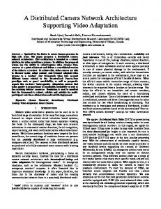
Figure 3: Structure of the information matrix for the full trajectory. The information matrix is a block tridiagonal symmetric matrix, due to the Markov structure of the process. N steps, the storage required is O(N 2 ). However, in this case, as it can be noticed from the prediction and updating equations, the matrix structure is block tridiagonal and symmetric (see Figure 3) at any time, and thus the storage required is O(N ). Also, the computational complexity of the prediction and updating steps is O(1), since they only deal with one block at each time instant instead of the whole trajectory. Moreover, the matrix structure allows the incorporation of delayed and asequent data, by adding their contribution to the corresponding elements of the information vector and matrix of the state trajectory. For standard robot operations, only the state trajectory over a time interval is needed, so these belief trajectories can be bounded. Note that the trajectories should be longer than the maximum expected delay in the network in order not to miss any measurement.
2.7.2
Decentralized Information Filter
In a multi-robot case the delayed-state EIF can be easily decentralized. Each robot i only has to run locally Algorithm 1, updating its full trajectory state with the information obtained from its sensors. Besides, when This is a preprint of an article published in Journal of Field Robotics: A Distributed Architecture for a Robotic Platform with Aerial Sensor Transportation and Self-Deployment Capabilities, Ivan Maza, Fernando Caballero, Jesus Capitan, J.R. Martinez-de-Dios and Anibal Ollero, Journal of Field Robotics, Volume 28, Issue 3, pages 303-328, Copyright 2011 Wiley-Blackwell). Available online on Wiley-Blackwell’s website: http://dx.doi.org/10.1002/rob.20383
it receives information from another robot j given by ξ j,t and Ωj,t , it can update its own estimation:
Ωi,t ← Ωi,t + Ωj,t − Ωij,t
(6)
ξi,t ← ξ i,t + ξj,t − ξ ij,t
(7)
which only requires the use of a separate EIF to maintain Ωij,t and ξij,t (which represent the common information exchanged between i and j in the past). This fusion rule leads to the exact centralized solution just in case the common information can be determined assuming a tree-shaped network topology, i.e. without cycles or duplicated information paths (Capitan et al., 2009). Nevertheless, a fixed network topology is a hard constraint for a system with multiple mobile robots. In this case, the common information between each pair of robots would be unknown and, in order to obtain consistent estimations, a conservative fusion rule must be used, so that the system does not become overconfident despite the presence of duplicated information. There is an analytic solution for this conservative fusion rule with IFs, which is the Covariance Intersection (Julier and Uhlmann, 1997):
Ωi,t ← ωΩi,t + (1 − ω)Ωj,t
(8)
ξ i,t ← ωξi,t + (1 − ω)ξ j,t
(9)
for ω ∈ [0 1]. It can be observed that the estimation is consistent (in the sense that no overconfident estimations are carried out) for any ω. The value of ω can be selected following some criteria, such as maximizing the obtained determinant of Ωi,t (minimizing the entropy of the final distribution). The option chosen by the authors is to use ω as a fixed weight that shows the system confidence in its own estimation along with those of the neighbors. It is important to remark that despite the fact that the delayed states allow the system to deal with communication latencies more robustly, some information is still lost with respect to the purely centralized filter when the Covariance Intersection or non-linear models are employed.
This is a preprint of an article published in Journal of Field Robotics: A Distributed Architecture for a Robotic Platform with Aerial Sensor Transportation and Self-Deployment Capabilities, Ivan Maza, Fernando Caballero, Jesus Capitan, J.R. Martinez-de-Dios and Anibal Ollero, Journal of Field Robotics, Volume 28, Issue 3, pages 303-328, Copyright 2011 Wiley-Blackwell). Available online on Wiley-Blackwell’s website: http://dx.doi.org/10.1002/rob.20383
2.7.3
Perception Models
The prediction and measurement models in equations (4) and (5) vary depending on the nature of the object (static or dynamic) and the particular sensor. Due to the existence of different subsystems, the perception system has to deal with heterogeneous measurements. Even though a more detailed description of the AWARE components is made in Section 3, some considerations regarding the heterogeneous measurement functions gt (Xt ) must be noted here:
• there is a Wireless Sensor Network (WSN) that provides 3D estimations on the position of an object in the world coordinate system, so its gt (Xt ) is linear. That object can be one sensor of the network being carried by a person, or a certain alarm (fire, smoke) detected by the network. Since every moving node reports its identifier, the data association regarding these measurements is straightforward. • there is a ground camera network in which each fixed camera can provide measurements on the image plane. The position of the tracked objects can be transformed into the world coordinate system by means of the camera pin-hole model and a knowledge of the cameras poses and calibrations. Local data association is solved by projecting the state estimation on the image plane and computing the Mahalanobis distance to the measurements. • the UAVs also obtain observations on the image plane with their cameras (visual or infrared), and then gt (Xt ) is again the camera pin-hole model.
Further details about the above models can be found in (Capitan et al., 2009). This work also explains how 3D estimations can be obtained with the WSN by means of the received signal strength from the mobile node. In field experiments the WSN was used to initialize the estimations of the objects of interest and assign univocal identifiers to them (wireless nodes identifiers). Thus, all the objects had the same identifier for every subsystem, thus removing the need to deal with data association among them.
3
Experimentation Scenario in the AWARE Project
In order to verify the success in reaching the objectives, the project considered the validation in Disaster Management/Civil Security (DMCS) applications involving: exploration of an area, detection, precise localization, deployment of the infrastructure, monitoring the evolution of the objects of interest, and providing This is a preprint of an article published in Journal of Field Robotics: A Distributed Architecture for a Robotic Platform with Aerial Sensor Transportation and Self-Deployment Capabilities, Ivan Maza, Fernando Caballero, Jesus Capitan, J.R. Martinez-de-Dios and Anibal Ollero, Journal of Field Robotics, Volume 28, Issue 3, pages 303-328, Copyright 2011 Wiley-Blackwell). Available online on Wiley-Blackwell’s website: http://dx.doi.org/10.1002/rob.20383
reactivity against changes in the environment and the loss of the required connectivity of the network. Actuators, such as fire extinguishers, to generate actions in real-time from the information provided by the sensors were also considered.
Building
Outdoors Fire Machine
WSN area
Barrels
Ground Cameras
Figure 4: Elements located in the surroundings of the building during the experiments.
Three general experiments, one per year of the project, in a common scenario (see Figure 4) were conducted to test the functionalities required for the validation. The particular components integrated in the AWARE platform during the experiments were the following:
• Two types of Unmanned Aerial Vehicles (UAVs) equipped with visual/infrared cameras or deployment devices: – TUB-H helicopter (see Figure 5(a)) developed by the Technische Universit¨at Berlin. – FC III E SARAH helicopter (Electric Special Aerial Response Autonomous Helicopter) developed by the Flying-Cam company (see Figure 5(b)). • A network of ground cameras mounted on tripods at known positions. In particular, two visual cameras to monitor the area of interest and an infrared camera to monitor the fire in the building. • A Wireless Sensor Network (WSN) equipped with different types of sensors (temperature, humidity, CO, smoke, etc.) and with mobile nodes. This network allows the detection of potential alarms like This is a preprint of an article published in Journal of Field Robotics: A Distributed Architecture for a Robotic Platform with Aerial Sensor Transportation and Self-Deployment Capabilities, Ivan Maza, Fernando Caballero, Jesus Capitan, J.R. Martinez-de-Dios and Anibal Ollero, Journal of Field Robotics, Volume 28, Issue 3, pages 303-328, Copyright 2011 Wiley-Blackwell). Available online on Wiley-Blackwell’s website: http://dx.doi.org/10.1002/rob.20383
a fire in the area. If a fireman carries one of the mobile nodes, information about its position can be also obtained with an average error of 3 meters approximately. • The Human Machine Interface: A software application designed to monitor the state of the different components of the platform and to allow the specification of the missions to be carried out. The main window of the application provides a map of the area with different elements: existing infrastructures, location and heading of the UAVs, projection on the ground of the field of view of the cameras, location of each node of the WSNs along with the coverage area of the network, paths planned by each UAV, estimation of the locations (and associated uncertainty) of the objects of interest detected by the platform, etc. The main menu provides access to additional information and functionalities: detailed state of each component, images captured by the cameras, tools for the specification of missions/tasks, the state of the communication channels, task execution status, etc. Figures 8, 9 and 11 shows the interface during the execution of three different missions.
(a) TUB-H helicopters
(b) FC III E SARAH helicopter
Figure 5: Autonomous helicopters in the platform. The experimentation scenario was installed in the facilities of the Protec-Fire company (Iturri group) located in Utrera (Spain). A structure was used to emulate a building where an emergency could be declared. In the structure there were several nodes of the WSN that would provide an alarm if a potential fire was detected. During the experiments, fire and smoke machines were used to produce controlled fires in the building. In the surroundings of the building the following elements were also present (see Figure 4):
• An area with WSN nodes grid-pattern deployed on the ground. This is a preprint of an article published in Journal of Field Robotics: A Distributed Architecture for a Robotic Platform with Aerial Sensor Transportation and Self-Deployment Capabilities, Ivan Maza, Fernando Caballero, Jesus Capitan, J.R. Martinez-de-Dios and Anibal Ollero, Journal of Field Robotics, Volume 28, Issue 3, pages 303-328, Copyright 2011 Wiley-Blackwell). Available online on Wiley-Blackwell’s website: http://dx.doi.org/10.1002/rob.20383
• Several barrels close to the building. The fire declared in the building could propagate to its surroundings and reach other infrastructures with devastating consequences. In this respect the barrels are intended to simulate fuel tanks that could be located around the building. • A fire machine for outdoors used to simulate a possible propagation of the fire from the building to other infrastructures. • Several dummy bodies used as victims in the building and also on the ground. • A fire truck equipped with an automated water cannon.
4
Multi-UAV Missions in the AWARE General Experiments
During the AWARE field experiments different multi-UAV missions were performed in order to validate the distributed software architecture. These missions included:
• UAV sensor deployment to extend the WSN coverage. • UAV fire confirmation and extinguishing. • Multi-UAV surveillance. • Single and multi-UAV load transportation. • Multi-UAV firemen tracking.
The missions could also be sequenced if the corresponding preconditions to start were satisfied. For instance, after the deployment of sensors, a mission for fire confirmation and extinguishing could start if a fire had been detected by these sensors. A summary of the different multi-UAV missions carried out in the AWARE field experiments, along with the components involved, is shown in Table 3. The integrated missions included coordinated flights involving node deployment, fire detection, monitoring and extinguishing, surveillance using two coordinated helicopters, tracking of firemen using two coordinated helicopters, load transportation using a single helicopter, and load transportation using three coupled helicopters. This is a preprint of an article published in Journal of Field Robotics: A Distributed Architecture for a Robotic Platform with Aerial Sensor Transportation and Self-Deployment Capabilities, Ivan Maza, Fernando Caballero, Jesus Capitan, J.R. Martinez-de-Dios and Anibal Ollero, Journal of Field Robotics, Volume 28, Issue 3, pages 303-328, Copyright 2011 Wiley-Blackwell). Available online on Wiley-Blackwell’s website: http://dx.doi.org/10.1002/rob.20383
Table 3: Different AWARE missions with an indication of the subsystems involved in each one. GC and FT stand for ground cameras and fire truck, respectively. The fire truck was equipped with an automated water cannon. HMI UAV GC WSN FT Mission Brief description 1 Firemen tracking X X X X 2 Firemen tracking X X X X 3 Surveillance X X 4 Node deployment & fire monitoring X X X X 5 Node deployment & fire monitoring X X X X 6 Fire monitoring X X X X 7 Surveillance X X X 8 Load transportation X X 9 Node deployment X X X 10 Fire monitoring X X X X X 11 Surveillance X X X 12 Node deployment X X X Different videos with the live execution of the missions presented in this paper are included in Table 7. The videos contain some fragments of the full mission and alternate views of the HMI screen along with the motion of the helicopters from an external camera. All the missions were planned and demonstrated over several days in the last year of the project. In addition, a final demonstration day was organized with the attendance of the European Commission reviewers and potential end-users. The four types of missions in Table 3 will be explained in further detail in the next sections, starting with the two involving the performance of the aerial robots in the environment.
4.1
Node Deployment and Fire Monitoring
This mission (identified as #5 in Table 3) was performed on 25th May 2009. The initial situation was as follows:
• A fire alarm has been declared inside the building by the WSN. This fire has been also confirmed with the ground cameras outside the building. • After a surveillance mission several fuel barrels close to the building have been localized.
There were two UAVs ready to fly on the landing pads:
• UAV 1 equipped with an infrared camera aligned with the fuselage and pointing downwards 45◦ . • UAV 2 equipped with the node deployment device (NDD) and three sensor nodes. This is a preprint of an article published in Journal of Field Robotics: A Distributed Architecture for a Robotic Platform with Aerial Sensor Transportation and Self-Deployment Capabilities, Ivan Maza, Fernando Caballero, Jesus Capitan, J.R. Martinez-de-Dios and Anibal Ollero, Journal of Field Robotics, Volume 28, Issue 3, pages 303-328, Copyright 2011 Wiley-Blackwell). Available online on Wiley-Blackwell’s website: http://dx.doi.org/10.1002/rob.20383
As there was a risk of fire propagation from the building to the fuel barrels, a deployment mission was specified in order to place several sensors in between at the locations of the waypoints wp1, wp2 and wp3 (see Figure 6). Let us denote the corresponding tasks as τ 8 , τ 9 and τ 10 , respectively.
120 110
y(m) − South to North
100 Building 90
wp6
wp1
wp7
Barrels
wp5
80
wp2 wp3
70 Tents 60 wp4
50 40 40
wp8 50
60
70 80 90 x(m) − East to West
100
110
120
Figure 6: Paths followed by the two helicopters during the node deployment and fire monitoring mission (Mission #5). Red and blue are UAVs 1 and 2, respectively. The waypoints are represented by small squares.
The distributed negotiation process for the sensor deployment tasks started and the messages interchanged are shown in Figure 7. The negotiation is based on the SIT algorithm described in Section 2.5. The HMI application announced the three tasks and the two UAVs bid for them. The bids from UAV 1 were infinite because it was not equipped with the NDD. Regarding UAV 2, it bid with the insertion cost of the tasks computed using the distance to the waypoints as metric. When bidding, the plan builder module checks different insertion points in the current plan in order to find the lowest associated cost (lowest bid). The mechanism is also illustrated in Figure 7, which shows the different possible partial plans once each new task was announced. When τ 8 was received, the whole plan including the take-off, home and land tasks was built. Then, τ 10 was received and two insertion points (represented with small arrows) were evaluated with equal resulting bids (the bid in the gray box was chosen arbitrarily). Finally, τ 9 was announced and three insertion points were evaluated. The lowest insertion cost (0.54) was achieved with task τ 9 inserted between tasks τ 8 and τ 10 . This is a preprint of an article published in Journal of Field Robotics: A Distributed Architecture for a Robotic Platform with Aerial Sensor Transportation and Self-Deployment Capabilities, Ivan Maza, Fernando Caballero, Jesus Capitan, J.R. Martinez-de-Dios and Anibal Ollero, Journal of Field Robotics, Volume 28, Issue 3, pages 303-328, Copyright 2011 Wiley-Blackwell). Available online on Wiley-Blackwell’s website: http://dx.doi.org/10.1002/rob.20383
ANNOUNCE τ 8 BID 92.88
BID ∞
ACCEPT BID ANNOUNCE τ 10
-
BID 7.36
BID ∞
ACCEPT BID ANNOUNCE τ 9 BID 0.54
BID ∞
τ27 TAKE-OFF τ28 DEPLOY(wp1) τ211 HOME τ212 LAND τ27 TAKE-OFF 8 τ2 DEPLOY(wp1) τ210 DEPLOY(wp3) τ211 HOME τ212 LAND
Plan building process
-
τ27 TAKE-OFF 10 τ2 DEPLOY(wp3) τ28 DEPLOY(wp1) τ211 HOME τ212 LAND
BID 7.36
7 - τ2 TAKE-OFF ACCEPT BID τ29 DEPLOY(wp2) τ 8 DEPLOY(wp1) - 2 9 REQUEST TOKEN τ28 DEPLOY(wp1) τ2 DEPLOY(wp2) BID 1.83 10 GIVE TOKEN τ210 DEPLOY(wp3) τ2 DEPLOY(wp3) ANNOUNCE τ 8 τ211 HOME τ211 HOME 12 BID ∞ τ212 LAND τ2 LAND BID ∞
τ27 TAKE-OFF
ANNOUNCE τ 10 BID ∞
BID ∞
ANNOUNCE τ 9 BID ∞ HMI
UAV 1
BID ∞
t ? 8 10 τ , τ and τ 9 allocated to UAV 2 UAV 2
τ27 TAKE-OFF 8 τ2 DEPLOY(wp1) τ210 DEPLOY(wp3) τ29 DEPLOY(wp2) τ211 HOME τ212 LAND
BID 9.73
Figure 7: The messages interchanged between the HMI and the UAVs for the allocation of the sensor deployment tasks (Mission #5) are shown on the left. The labels of the arrows representing the messages are always above them. The partial plans built by UAV 2 during the negotiation process are depicted on the right (the small arrows represent the different insertion points checked by the planner). For instance, when the last task (τ 9 ) was announced, three insertion points were evaluated. The lowest insertion cost (0.54) was achieved with task τ 9 inserted between tasks τ 8 and τ 10 .
This is a preprint of an article published in Journal of Field Robotics: A Distributed Architecture for a Robotic Platform with Aerial Sensor Transportation and Self-Deployment Capabilities, Ivan Maza, Fernando Caballero, Jesus Capitan, J.R. Martinez-de-Dios and Anibal Ollero, Journal of Field Robotics, Volume 28, Issue 3, pages 303-328, Copyright 2011 Wiley-Blackwell). Available online on Wiley-Blackwell’s website: http://dx.doi.org/10.1002/rob.20383
All the tasks were initially allocated to UAV 2. According to the SIT algorithm, UAV 2 asked for the token to announce again the tasks won. The HMI application sent the token to UAV 2 and tasks τ 8 , τ 9 and τ 10 were announced again. All the bids received were infinite, so the tasks were definitely allocated to UAV 2: τ28 , τ29 and τ210 . Each deployment task was then decomposed by the task refining module into four elementary tasks:
1. Reach the waypoint. 2. Go down until an altitude hd with respect to the ground (or any obstacle) is reached. 3. Activate the on-board device for dropping the sensor. 4. Go up to the initial waypoint altitude.
Once decomposed, the following twelve elementary tasks were inserted into the plan, substituting tasks τ28 , τ29 and τ210 :
ˆ 8 = GOTO) • τ28 → {1 τˆ28 ,2 τˆ28 ,3 τˆ28 ,4 τˆ28 } (λ ˆ 9 = GOTO) • τ29 → {1 τˆ29 ,2 τˆ29 ,3 τˆ29 ,4 τˆ29 } (λ ˆ 10 = GOTO) • τ210 → {1 τˆ210 ,2 τˆ210 ,3 τˆ210 ,4 τˆ210 } (λ
After the execution of the deployment tasks, during the landing maneuver of UAV 2, a new fire alarm was declared by one of the deployed sensors between the building and the barrels. In order to confirm this second fire, a take-shot task (τ 2 ) was specified: take images from the west of the fire at an altitude of 75 meters. A negotiation process started, and the task was allocated to UAV 1 (τ12 ), which was equipped with an infrared camera (UAV 2 had no cameras on-board and its bids were infinite). Task τ12 was processed by the task refining toolbox in order to compute the waypoint that fulfilled the above constraints and allowed the fire to be in the center of the field of view of the on-board camera. Once the fire was confirmed, the platform operator commanded a fire truck equipped with a remotely controlled water cannon (monitor) to extinguish it. Before activating the monitor, UAV 1 was commanded to move to a safe location (task τ13 ). After the operation with the monitor, the user again commanded a take-shot task τ14 for UAV 1 in order to confirm that the fire was extinguished. After the confirmation, the UAV returned home and landed (tasks τ15 and τ16 ). This is a preprint of an article published in Journal of Field Robotics: A Distributed Architecture for a Robotic Platform with Aerial Sensor Transportation and Self-Deployment Capabilities, Ivan Maza, Fernando Caballero, Jesus Capitan, J.R. Martinez-de-Dios and Anibal Ollero, Journal of Field Robotics, Volume 28, Issue 3, pages 303-328, Copyright 2011 Wiley-Blackwell). Available online on Wiley-Blackwell’s website: http://dx.doi.org/10.1002/rob.20383
All of the tasks described above, along with their decomposition into elementary tasks, are summarized in Table 4. Table 4: Tasks executed during Mission #5 and their decomposition in elementary tasks. − ˆ τik λ Ω Ω+ Decomposition Π 1 1 1 ˆ1 1 ˆ1 τ1 TAKE-OFF PRE-FLIGHT_CHECK ∅ τˆ1 (λ = TAKE-OFF) Π1 2 1 1 2 ˆ2 1 ˆ2 τ1 TAKE-SHOT END(τ1 ) ∅ τˆ1 (λ = GOTO) Π1 1 3 ˆ3 1 ˆ3 τ13 GOTO END(τ12 ) ∅ τˆ1 (λ = GOTO) Π1 1 4 ˆ4 1 ˆ4 τ14 TAKE-SHOT END(τ13 ) ∅ τˆ1 (λ = GOTO) Π1 1 5 ˆ5 1 ˆ5 τ15 HOME END(τ14 ) ∅ τˆ1 (λ = GOTO) Π1 6 5 1 6 ˆ6 1 ˆ6 τ1 LAND END(τ1 ) ∅ τˆ1 (λ = LAND) Π1 1 7 ˆ7 1 ˆ7 τ27 TAKE-OFF PRE-FLIGHT_CHECK ∅ τˆ2 (λ = TAKE-OFF) Π2 1 ˆ8 ˆ 8 = GOTO) τ28 DEPLOY(wp1) END(τ27 ) ∅ {1 τˆ28 ,2 τˆ28 ,3 τˆ28 ,4 τˆ28 } (λ Π2 9 8 1 9 2 9 3 9 4 9 9 1 ˆ9 ˆ τ2 DEPLOY(wp2) END(τ2 ) ∅ { τˆ2 , τˆ2 , τˆ2 , τˆ2 } (λ = GOTO) Π2 ˆ 10 = GOTO) 1 Π ˆ 10 τ210 DEPLOY(wp3) END(τ29 ) ∅ {1 τˆ210 ,2 τˆ210 ,3 τˆ210 ,4 τˆ210 } (λ 2 1 11 ˆ 11 1 ˆ 11 τ211 HOME END(τ210 ) ∅ τˆ2 (λ = GOTO) Π2 1 12 ˆ 12 1 ˆ 12 τ212 LAND END(τ211 ) ∅ τˆ2 (λ = LAND) Π2 The paths followed by the two helicopters are shown in Figure 6. The small squares represent the waypoints corresponding to the elementary GOTO tasks:
• UAV 1 (red line): – wp5, wp7: locations computed to monitor the fire. – wp6: safe waypoint to wait for the monitor operation to be over. – wp8: UAV 1 home. • UAV 2 (blue line): – wp1, wp2, wp3: deployment locations. – wp4: UAV 2 home.
Finally, a screenshot of the HMI application taken during the execution of the mission is shown in Figure 8. It can be seen how UAV 1 is monitoring the fire detected by the sensors deployed: a window shows the images captured by the infrared camera on-board with a red overlay corresponding to the fire detected.
4.2
Load Transportation
In this mission (identified as #8 in Table 3) a fire alarm had been declared in the building and the objective was to place a wireless camera with pan-tilt on the top floor. The camera would provide continuous realtime video to monitor the operations of the firemen and the health status of the victims on the top floor This is a preprint of an article published in Journal of Field Robotics: A Distributed Architecture for a Robotic Platform with Aerial Sensor Transportation and Self-Deployment Capabilities, Ivan Maza, Fernando Caballero, Jesus Capitan, J.R. Martinez-de-Dios and Anibal Ollero, Journal of Field Robotics, Volume 28, Issue 3, pages 303-328, Copyright 2011 Wiley-Blackwell). Available online on Wiley-Blackwell’s website: http://dx.doi.org/10.1002/rob.20383
Figure 8: Screenshot of the platform human machine interface during the execution of Mission #5: sensor deployment and fire monitoring. The estimated location of the fire is represented by an ellipse and the alarms triggered by the sensors are shown as filled red circles on the map. The images from the infrared camera on-board are displayed on the window at the right. The status of the tasks is on the table above the images. On the left, the UAV is represented by a small arrow and the field of view of its on-board camera is shadowed on the map.
of the building. The weight of the camera and its associated communication equipment and batteries were too heavy for a single helicopter, and hence, several helicopters were required. To the best of the authors knowledge, this was the first field experiment involving the transportation of a load from the ground to the top floor of a building with three autonomous helicopters. The Load Transportation System (LTS) (Maza et al., 2010) developed by the Technical University of Berlin was ready on the landing pads with the load connected by ropes to three helicopters of type TUB-H. The platform operator specified a load transportation task to deploy the wireless pan-tilt camera on the top floor and the plan builder module generated the full set of ordered tasks for the LTS. The plan refiner toolbox then decomposed the plan into elementary tasks to be sent to the executive layer. It should be noted that the enormous complexity of the load transportation system composed by three helicopters was hidden to the user, who could proceed to the specification of the deployment task by simply providing the GPS location where the load was required. The altitude specified for the deployment was several meters above the top floor of the building. The ODL had access to the map of the area in order to plan the deployment task decomposition properly, also taking into account the length of the ropes. This is a preprint of an article published in Journal of Field Robotics: A Distributed Architecture for a Robotic Platform with Aerial Sensor Transportation and Self-Deployment Capabilities, Ivan Maza, Fernando Caballero, Jesus Capitan, J.R. Martinez-de-Dios and Anibal Ollero, Journal of Field Robotics, Volume 28, Issue 3, pages 303-328, Copyright 2011 Wiley-Blackwell). Available online on Wiley-Blackwell’s website: http://dx.doi.org/10.1002/rob.20383
Finally, a screenshot of the HMI software captured during the execution of the mission is shown in Figure 9. At that point of the execution, the wireless camera had been deployed on the top floor of the building and the LTS was still over the building after releasing the ropes.
(a) (left) Map of the area with the position and heading of the three LTS (b) The operator has used the camera helicopters represented by arrows; (right) images transmitted by the Flying- with pan-tilt to find one victim Cam helicopter and telemetry from all the UAVs
Figure 9: Screenshot of the platform human machine interface during the execution of Mission #8. The camera is deployed on the top floor of the building. The LTS is still over the deployment location after releasing the ropes.
4.3
Multi-UAV Surveillance
In this mission (identified as #7 in Table 3) a fire alarm had been declared in a building and the objective was to find objects of interest (fuel barrels) in the area around it. The propagation of the fire could reach those barrels and make the extinguishing task more difficult for the firemen. The platform operator specified a surveillance task to localize the barrels and display them on the map of the HMI. Basically, the user specified the vertices of the area to be covered, the altitude for the flight, the UAVs’ speed and the overlapping between images due to the associated zigzag pattern. The algorithms (Maza and Ollero, 2007) integrated in the task refining toolbox to decompose this task were developed considering their computational complexity in order to allow near-real time operation. The problem is divided into the subproblems of (1) UAVs’ relative capabilities computation, (2) cooperative area assignment, and (3) efficient area coverage. First, an algorithm based on a divide-and-conquer, sweep-line approach is applied to divide the whole area taking into account UAV’s relative capabilities and initial locations. The resulting subareas are then allocated to the UAVs, that can cover them using a zigzag pattern. Each UAV computes the sweep direction that minimizes the number of turns needed along the zigzag pattern. The sensing capabilities on-board the UAVs are taken into account in the area partition and zigzag pattern computations. This is a preprint of an article published in Journal of Field Robotics: A Distributed Architecture for a Robotic Platform with Aerial Sensor Transportation and Self-Deployment Capabilities, Ivan Maza, Fernando Caballero, Jesus Capitan, J.R. Martinez-de-Dios and Anibal Ollero, Journal of Field Robotics, Volume 28, Issue 3, pages 303-328, Copyright 2011 Wiley-Blackwell). Available online on Wiley-Blackwell’s website: http://dx.doi.org/10.1002/rob.20383
In this mission two UAVs were available and ready in the landing pads, both equipped with fixed visual cameras aligned with the fuselage and pointing downwards 90◦ . The vertices of the whole polygon specified by the user, that was later divided into the blue and red sub-areas is shown in Figure 10. 110 building 100
90
wp8
wp9
wp7
wp6
y(m) - South to North
80 wp4
wp5
wp3
70
wp2 wp1
60
wp12
wp13
wp10
wp11 50
wp8 tents
40
wp10 wp14
wp9
wp7
wp6 wp4
wp5 wp3
30
wp2 wp1
20
50
60
70
80
90 100 x(m) - East to West
110
120
130
Figure 10: Paths followed by the two helicopters during the multi-UAV surveillance mission (Mission #7). The waypoints are represented by small squares and each computed subarea is shadowed in a different color.
The distributed negotiation for the surveillance task has a different goal when compared to the previously presented missions: The different bids are used by the auctioneer to compute the relative capabilities of the available UAVs for the partition process. These proportions are represented in the following by a set of n ∑ values ci , i = 1, . . . , n, with 0 < ci < 1 and ci = 1. i=1
Once the surveillance task was announced by the HMI application, the two available UAVs started with the negotiation process by bidding with their particular capabilities for the execution. Each bid was computed by the task refining toolbox module as
bi = wi Pdi ,
(10)
where wi was the sensing width of the on-board camera and Pdi was the probability of detection associated with the sensor given that the object of interest is in its field of view. Those values were computed taking into account the specified altitude and the parameters of the on-board cameras. This is a preprint of an article published in Journal of Field Robotics: A Distributed Architecture for a Robotic Platform with Aerial Sensor Transportation and Self-Deployment Capabilities, Ivan Maza, Fernando Caballero, Jesus Capitan, J.R. Martinez-de-Dios and Anibal Ollero, Journal of Field Robotics, Volume 28, Issue 3, pages 303-328, Copyright 2011 Wiley-Blackwell). Available online on Wiley-Blackwell’s website: http://dx.doi.org/10.1002/rob.20383
The particular values computed in Mission #7 for the bids and the relative capabilities are shown in Table 5. In the last column the values for the relative capabilities computed by the auctioneer determine the percentage of the full area that was assigned to each UAV. Table 5: Values for the bids and resulting relative capabilities. wi Pdi bi ci UAV 1 5.17 0.901 4.65 0.5012 % UAV 2 5.76 0.803 4.63 0.4988 %
The task refining toolbox module of each UAV embeds exactly the same algorithm to obtain the area partition. Thus, once each UAV receives from the auctioneer the relative capabilities, it can compute the whole partition and its assigned sub-area. The task refining module of each UAV also computes the list of goto tasks required to cover the allocated sub-area based on the sensorial capabilities of each UAV and the flight altitude. The location of the waypoints computed for each UAV in its sub-area is shown in Figure 10. It should be mentioned that given the sensing widths wi shown in Table 5, the waypoints were determined taking into account the 100% overlap specified between consecutive rows. However, it can be observed that in the frontier between sub-areas the distance between rows of different UAVs is larger. This difference comes from the 0% overlap that is forced between sub-areas in order to increase the safety conditions of the UAVs. Finally, a screenshot captured from the HMI application during the execution of the mission is shown in Figure 11. On the right hand side of the screen there are two windows with the images received from the cameras on-board.
4.4
People Tracking
This mission (identified as #2 in Table 3) was carried out on 25th May 2009. Two firemen were located in the area in front of the building assisting injured people and moving equipment. The objective of the user was to have an estimation of the location of the firemen on the map and also images of their operations. Two UAVs were available and ready on the landing pads for this mission, both equipped with fixed visual cameras aligned with the fuselage and pointing downwards 45◦ . The firemen were equipped with sensor nodes, and an initial estimation of their location was based on the information from the WSN deployed in front of the building and from the visual estimations obtained by the ground camera network (Capitan et al., 2009). Later, when the UAVs took off, this information was also fused online with the estimations computed from the visual images gathered by the helicopters in order to decrease the uncertainty in the location of the firemen. This is a preprint of an article published in Journal of Field Robotics: A Distributed Architecture for a Robotic Platform with Aerial Sensor Transportation and Self-Deployment Capabilities, Ivan Maza, Fernando Caballero, Jesus Capitan, J.R. Martinez-de-Dios and Anibal Ollero, Journal of Field Robotics, Volume 28, Issue 3, pages 303-328, Copyright 2011 Wiley-Blackwell). Available online on Wiley-Blackwell’s website: http://dx.doi.org/10.1002/rob.20383
Figure 11: Screenshot of the platform HMI during the execution of a surveillance mission (Mission #7). On the right, two barrels in the images from the camera on-board UAV 2 can be identified. On the left, the UAVs are represented as small arrows and the fields of view of the on-board cameras are shadowed on the map (their shapes are approximately rectangles with the cameras pointing downwards). In the middle of the screen, two tables show the status of the different tasks. Two tasks of type TRACK(fireman2) were sent to the UAVs at different times:
• The first one was announced and allocated to UAV 2 due to its lowest bid (lowest insertion cost) during the distributed negotiation process based on the SIT algorithm (see Section 2.5). In order to compute the insertion cost for the tracking task, the required associated waypoint and heading were computed by the task refining toolbox module based on the following principles. Let us assume that a distributed estimation of the position pk (t) of each object of interest k is available. This estimation has an associated covariance or inertia matrix Ck . This matrix can be geometrically represented as a 3σ ellipse in the x − y plane. The matrix M describing the shape of an ellipse (x − k)T M(x − k) = 1 is related to the covariance matrix of the same ellipse (Forss´en, 2004) according to
M=
1 −1 C . 4
(11)
From this equation it is possible to compute the main axis direction of the ellipse, i.e. the direction with higher uncertainty in the estimation of the position of the object. Let us consider an object with coordinates [ xo
yo
T zo ] and main axis vector v1 = [ v1x
T v1y ] .
This is a preprint of an article published in Journal of Field Robotics: A Distributed Architecture for a Robotic Platform with Aerial Sensor Transportation and Self-Deployment Capabilities, Ivan Maza, Fernando Caballero, Jesus Capitan, J.R. Martinez-de-Dios and Anibal Ollero, Journal of Field Robotics, Volume 28, Issue 3, pages 303-328, Copyright 2011 Wiley-Blackwell). Available online on Wiley-Blackwell’s website: http://dx.doi.org/10.1002/rob.20383
The objective is to compute a location and orientation for the UAV that would allow an improvement in the estimation of the object of interest. Let us denote the coordinates of the observation point w by [ xw
yw
T zw ] and the desired orientation for the UAV by the roll (γw ), pitch (βw ) and yaw T z ] . The following constraints
(αw ) angles. The initial location of the UAV is located at [ x y should be satisfied to improve the estimation:
1. The object should be in the center of the field of view, i.e. mw = [ w/2 h/2 ]T for an image resolution of w × h pixels. 2. The UAV altitude for the monitoring task is zw = zo + zΠ , where zΠ is a parameter based on the camera resolution. 3. The location of the UAV is in the perpendicular line to the main axis that crosses the estimated location of the object (see Figure 12(a)). From the two possible solutions [ xw1 yw1 ]T and √ [ xw2 yw2 ]T , the waypoint closer to the UAV is selected. Thus, if (xw1 − x)2 + (yw1 − y)2 ≤ √ (xw2 − x)2 + (yw2 − y)2 v1x (xw1 − xo ) v1y
(12)
v1x (xw2 − xo ). v1y
(13)
yw1 − yo = − and otherwise
yw2 − yo = −
4. The yaw αw of the UAV is computed to have the UAV pointing towards the object in the direction perpendicular to the main axis v1 of the uncertainty ellipse, whereas the pitch and roll are set to zero for simplicity (βw = γw = 0). Then, using the north as zero reference for the yaw angle and assuming clockwise positive, its value will be given by
αw =
π − arctan 2
(
yo − yw xo − xw
) .
(14)
Once the waypoint computed following these rules was reached, the UAV captured images from the fireman (labelled as fireman2) and processed them in order to contribute to the estimation of his position. UAV 2 broadcasted its position relative to the tracked object location; if more tracking tasks for the same object were commanded, the next UAVs will need this information to compute their positions around the object accordingly. • Later, the second task was announced and allocated to UAV 1 (UAV 2 bid with infinite cost because This is a preprint of an article published in Journal of Field Robotics: A Distributed Architecture for a Robotic Platform with Aerial Sensor Transportation and Self-Deployment Capabilities, Ivan Maza, Fernando Caballero, Jesus Capitan, J.R. Martinez-de-Dios and Anibal Ollero, Journal of Field Robotics, Volume 28, Issue 3, pages 303-328, Copyright 2011 Wiley-Blackwell). Available online on Wiley-Blackwell’s website: http://dx.doi.org/10.1002/rob.20383
UAV 1 alt: 70.00
wp2
UAV 2 alt: 70.00
wp1
UAV 1 alt: 70.00
wp1
v1
v1 x object2 alt: 55.32
(a) Location for object monitoring with one UAV
x object2 alt: 55.32
(b) Locations for object monitoring with two UAVs
Figure 12: Waypoint computation for object monitoring tasks. For a single UAV, its location will be in the perpendicular line to the main axis that crosses the estimated location of the object. From the two possible solutions, the waypoint closer to the initial UAV position is selected. If more than one UAV is commanded to monitor the same object, the location is alternatively chosen between the perpendicular and parallel lines to the main axis that crosses the estimated location of the object. it was already tracking the same object). In general, if more than one UAV is commanded to monitor the same object, the first one will follow the above mentioned rules, but the second and next UAVs will consider the places already occupied around that object. In this case, the location is alternatively chosen between the perpendicular and parallel lines to the main axis that crosses the estimated location of the object. Then, as it can be observed in Figure 12(b), if two UAVs are commanded to monitor the same object, the first one chooses the closest location in the perpendicular line, whereas the second will be located in the closest waypoint in the parallel line.
The trajectories followed by the UAVs during the execution of the mission are shown in Figure 13. The waypoints labelled as wp1 and wp4 are initial locations defined by the user for each UAV after take-off. The WSN and ground cameras of the platform started to provide estimations from the fireman labelled as fireman2. Based on those estimations, the tracking tasks can be sent to the UAVs. In the case of UAV 1, the computed waypoint wp2 for the observation was very close to the first waypoint, but the heading was different. In order to verify the decentralized data fusion approach summarized in Section 2.7, a centralized filter was used to provide the ground truth of the fireman tracking. Centralized estimations are not affected by communications delays, double counting of information, asynchronous data or partial information. Comparison This is a preprint of an article published in Journal of Field Robotics: A Distributed Architecture for a Robotic Platform with Aerial Sensor Transportation and Self-Deployment Capabilities, Ivan Maza, Fernando Caballero, Jesus Capitan, J.R. Martinez-de-Dios and Anibal Ollero, Journal of Field Robotics, Volume 28, Issue 3, pages 303-328, Copyright 2011 Wiley-Blackwell). Available online on Wiley-Blackwell’s website: http://dx.doi.org/10.1002/rob.20383
110
Building Fireman 2
y(m) − South to North
100 90
wp2 Fireman 1
wp1 80
wp5
70 wp4 Tents 60 wp6 50 wp3 40 40
50
60
70 80 x(m) − East to West
90
100
110
Figure 13: Paths followed by the two helicopters during the people tracking mission (Mission #2). The trajectories in red and blue correspond to UAVs 1 and 2, respectively. The different waypoints of the elementary GOTO tasks are represented by squares. Some samples of the firemen trajectories during the experiment are also shown: red crosses denote the estimated position of the firemen and green ellipses stand for their uncertainty.
of the estimations of the cooperative perception system with a centralized filter provides a good measure of the efficiency of the cooperative approach. In addition, the aim of the AWARE perception system is to provide the best estimations using a distributed approximation, so the results can be compared to the optimal approach, i.e. the centralized scheme. Thus, all the sensor information provided by the WSN, camera network and UAV cameras, fed the distributed cooperative perception system. The decentralized filters launched a prediction/updating step every 0.2 seconds and included the local and neighbor measurements when available. Ground cameras and UAVs provided local measurements at 1Hz to 3Hz approximately, while the WSN updated local measurement at 10Hz. All this information generated the estimation presented in Figure 14 for firemen 1 and 2. The actual position of the firemen (estimated by means of the centralized filter) is also shown in the figure. Notice that the estimated standard deviation from the filter is coherent with the errors and is always within the 3σ confident interval. The estimation in the Z axis is not shown because throughout the experiment the firemen stayed on the ground, so the analysis of the results do not provide significant information about the performance of the perception system. It can also be seen that the average localization error for fireman 1 (top figure) is about 1 meter while for fireman 2 (bottom figure) it is about 1.5 meters during the entire trajectory. This error can be considered small if all the error sources are taken into account, that is, errors in the camera calibration, position, orientation and communications issues. This is a preprint of an article published in Journal of Field Robotics: A Distributed Architecture for a Robotic Platform with Aerial Sensor Transportation and Self-Deployment Capabilities, Ivan Maza, Fernando Caballero, Jesus Capitan, J.R. Martinez-de-Dios and Anibal Ollero, Journal of Field Robotics, Volume 28, Issue 3, pages 303-328, Copyright 2011 Wiley-Blackwell). Available online on Wiley-Blackwell’s website: http://dx.doi.org/10.1002/rob.20383
110
105
105
100
100
yUTM (m)
xUTM (m)
110
95
90
95
90
85
85
80
80
75 0
200
400
600
800
1000
1200
75 0
1400
200
400
sample
600
800
1000
1200
1400
sample
(a)
(b)
88
110
86 105
84
100
80
yUTM (m)
xUTM (m)
82
78 76
95
90
74 72
85
70 68 0
500
1000 sample
(c)
1500
80 0
500
1000
1500
sample
(d)
Figure 14: Estimated X and Y position of fireman 1 (Top) and fireman 2 (Bottom). Red: Estimation provided by the decentralized approach. Green: Estimated 3σ confidence interval of the decentralized approach. Black: Centralized estimation used as ground-truth.
This is a preprint of an article published in Journal of Field Robotics: A Distributed Architecture for a Robotic Platform with Aerial Sensor Transportation and Self-Deployment Capabilities, Ivan Maza, Fernando Caballero, Jesus Capitan, J.R. Martinez-de-Dios and Anibal Ollero, Journal of Field Robotics, Volume 28, Issue 3, pages 303-328, Copyright 2011 Wiley-Blackwell). Available online on Wiley-Blackwell’s website: http://dx.doi.org/10.1002/rob.20383
As an example, the standard deviation computed by the decentralized approach and the estimation with the centralized filter for fireman 2 are shown in Figure 15. As expected, the decentralized approach presents more conservative estimations than the centralized filter because of communications issues, the Covariance Intersection algorithm, and the fact that the decentralized approach cannot access all the information at the same time as the centralized filter does. However, it is worth mentioning the closeness of the two estimations, which differ by one meter approximately. In general, the standard deviation grows during the prediction steps and decreases after updating with local or external information showing a high-frequency component. Since the centralized filter is accessing all of the information at every time step, it is updated more often, presenting a lower variation over the mean standard deviation. In the decentralized case the effect of the
5
5
4.5
4.5
4
4
3.5
3.5 y std. dev. (m)
x std. dev. (m)
longer prediction periods can be seen.
3 2.5
3 2.5
2
2
1.5
1.5
1
1
0.5 0
500
1000 sample
(a)
1500
0.5 0
500
1000
1500
sample
(b)
Figure 15: Estimated standard deviation in X and Y for fireman 2. Red: Estimation using the decentralized approach. Black: Centralized estimation Finally, the following paragraphs contain some figures in order to provide a clear picture of the sensor capabilities used in this experiment and how the proposed distributed data fusion approach benefits the global estimation. Figure 16 shows the position estimation of fireman 2 based on the received signal strength (RSSI) (using a Particle Filter method similar to the one described by Caballero (Caballero et al., 2008)) provided by the sensor node that the fireman carries. It can be observed that the sensor is very noisy, with an average error between 2 and 3 meters. It is important to mention that until sample 100 the centralized filter (used as ground-truth) only integrated information from the received signal strength filter, and for this reason the centralized filter matches very well with the RSSI sensor in the first samples. Although noisy, the RSSI-based estimation provides valuable information to the system. It becomes critical when bearing-only estimations are considered, such a single camera. The absence of scale factor could lead to filter divergence if a single camera do not triangulate enough with respect the target position. The This is a preprint of an article published in Journal of Field Robotics: A Distributed Architecture for a Robotic Platform with Aerial Sensor Transportation and Self-Deployment Capabilities, Ivan Maza, Fernando Caballero, Jesus Capitan, J.R. Martinez-de-Dios and Anibal Ollero, Journal of Field Robotics, Volume 28, Issue 3, pages 303-328, Copyright 2011 Wiley-Blackwell). Available online on Wiley-Blackwell’s website: http://dx.doi.org/10.1002/rob.20383
RSSI-based estimation intrinsically provides a bound for the scale of those cameras. This benefit will always be produced when absolute estimations (RSSI-based, beacons, GPS, ...) are integrated into the global
90
105
85
100
80
95
yUTM (m)
xUTM (m)
estimation.
75
70
65 0
90
85
500
1000 sample
(a)
1500
80 0
500
1000
1500
sample
(b)
Figure 16: Estimated X and Y position of fireman 2 based on the received signal strength provided by the wireless sensor network. Red: Estimation provided by the received signal strength filter. Green: Estimated 3σ confidence interval. Black: Centralized estimation with all the sensors used as ground-truth
The position estimation of fireman 2 based on the images of the helicopters is represented in Figure 17. The single estimation of each helicopter is not shown because they are bearing-only estimations, so triangulation from a different position is needed. The figure shows how the helicopters began the estimation at about sample 100 and how this estimation is good until sample 800 approximately, at which point one of the helicopters moved to a position where fireman 2 was out of the field of view and the estimated position diverged due to the lack of range in a single camera. It is easy to see that the estimation would be improved if another source of information such as a ground camera or the received signal strength localization were integrated with the helicopter’s information. In fact, the distributed data fusion approach presented in this paper automatically integrates all the data sources, taking into account their associated uncertainties and allowing a consistent global estimation better than that provided by the single sensors. In Figure 17 is also shown how the estimation provided by the UAVs is accurate when compared to the centralized filter. The optimal positions at which the UAVs took the images of the target are very significant to explain these good results. These positions where computed online during the experiment by means of the algorithm described above (Fig. 12). This is a preprint of an article published in Journal of Field Robotics: A Distributed Architecture for a Robotic Platform with Aerial Sensor Transportation and Self-Deployment Capabilities, Ivan Maza, Fernando Caballero, Jesus Capitan, J.R. Martinez-de-Dios and Anibal Ollero, Journal of Field Robotics, Volume 28, Issue 3, pages 303-328, Copyright 2011 Wiley-Blackwell). Available online on Wiley-Blackwell’s website: http://dx.doi.org/10.1002/rob.20383
110
105
100
100
yUTM (m)
xUTM (m)
90
80
95
90
70 85
60
50 0
500
1000
1500
80 0
sample
(a)
500
1000
1500
sample
(b)
Figure 17: Estimated X and Y position of fireman 2 based on the images gathered by the UAVs. Red: Estimation provided by a centralized filter integrating the images of both helicopters. Green: Estimated 3σ confidence interval. Black: Centralized estimation with all of the sensors used as ground-truth
5
Conclusions and Lessons Learned
The experiments with real UAVs presented in the paper have shown that the developed architecture allows coverage of a good spectrum of missions: surveillance, sensor deployment, fire confirmation and extinguishing. One of the key features of the architecture was the easy integration process of autonomous vehicles from different manufacturers and research groups. This characteristic made possible the use of different types of UAVs during the AWARE Project with low development efforts. The HMI application developed has proven to be highly usable, allowing the operator to exploit the capabilities of the platform easily. It is worth mentioning that the HMI was shut down and restarted during the execution of several missions and the platform performance was not affected at all due to the distributed nature of the decision making system. In addition, the design did not pose significant restrictions to the communication layer, so the coordination between the UAVs using a distributed approach was possible at a reasonable communication cost. Thus, the authors consider that the proposed approach represents a good balance between robustness, efficient decision making and communication resources. The autonomous capabilities provided by the ODL have allowed a single operator for mission design and execution during all the tests performed with the platform. The modules presented in this paper were used during all the missions and their behaviour was as expected. Some figures that illustrate the performance of the ODL during the twelve multi-UAV missions are presented in Table 6. The messages interchanged were mainly related to task synchronization and the required negotiations for task allocation and conflict resolution. This is a preprint of an article published in Journal of Field Robotics: A Distributed Architecture for a Robotic Platform with Aerial Sensor Transportation and Self-Deployment Capabilities, Ivan Maza, Fernando Caballero, Jesus Capitan, J.R. Martinez-de-Dios and Anibal Ollero, Journal of Field Robotics, Volume 28, Issue 3, pages 303-328, Copyright 2011 Wiley-Blackwell). Available online on Wiley-Blackwell’s website: http://dx.doi.org/10.1002/rob.20383
Table 6: Some figures that reflect the performance of the ODL during the twelve multi-UAV missions carried out in 2009. Mission # 1 2 3 4 5 6 7 8 9 10 11 12 Total Tasks received from the 9 10 8 12 12 6 8 3 4 6 8 4 86 HMI Elementary tasks sent to 9 10 22 21 21 6 28 3 7 6 18 8 151 the executive Tasks generated by the 4 4 18 13 13 3 24 0 3 3 14 3 99 task refiner Coordination messages 12 12 66 34 34 0 78 0 0 0 58 0 294 interchanged Potential conflicts man- 6 6 18 17 17 0 24 0 0 0 14 0 102 aged successfully
In addition, the decentralized data fusion scheme proposed was able to track the position of a moving object in a fully decentralized manner with small errors with respect to a centralized filter, with similar results obtained in terms of mean (about one meter error) and standard deviation (about half a meter difference). Here, the inclusion of the delayed states into the Information Filter allowed the system to cope with temporal communication breakdowns in an efficient manner. Among the lessons learned during the experiments, it is worth mentioning the relevance of the time synchronization when a distributed system is being tested. This synchronization affects not only the decision-making system but also the decentralized data fusion approach. In our platform, this issue was solved by using the Network Time Protocol (NTP) with a server connected through a serial port to a GPS base station. Using NTP allows timing information to be distributed in local area networks with errors below one millisecond, which satisfies the time constraints of the decentralized approaches implemented in the project. The selection of the appropriate communication system proved to be a crucial issue in this kind of distributed application. Many of the problems that have been addressed during the experiments are explicitly related with the physical communication layer and the communication middleware. From the hardware point of view, WiFi at 2.4GHz was the first approach because the existing technology allowed good bandwidth and mobility at a relatively low price. Each platform component (unmanned aerial vehicles, ground camera network and wireless sensor network) had a dedicated WiFi channel to prioritize traffic and ensure there were no interferences in critical communications such as commands to the UAVs. However, this choice was discarded after the experiments in the second year of the project due to channel interferences with other WiFi devices in the surroundings of the experimental area. WiFi is so extended that it is difficult to find free channels with some guarantees and, although communications were encrypted and MAC-Filtered, if an external device made intensive use of an AWARE system channel, the interferences significantly reduced the This is a preprint of an article published in Journal of Field Robotics: A Distributed Architecture for a Robotic Platform with Aerial Sensor Transportation and Self-Deployment Capabilities, Ivan Maza, Fernando Caballero, Jesus Capitan, J.R. Martinez-de-Dios and Anibal Ollero, Journal of Field Robotics, Volume 28, Issue 3, pages 303-328, Copyright 2011 Wiley-Blackwell). Available online on Wiley-Blackwell’s website: http://dx.doi.org/10.1002/rob.20383
bandwidth. This problem was solved by moving to WiFi at 5GHz, which is still less extended and has a smaller communication range, so interferences with external devices were significantly reduced. Regarding the AWARE communication middleware (Ollero et al., 2007), the experiments showed that fully decentralised publish/subscribe paradigms fit very well with this kind of applications in which high communication latency and eventual breakdowns are not unusual. This paradigm allowed simplification of the communication and connection procedures, which is critical when there exist, at least, fifteen different parallel software instances communicating with each other, as it was the case in the AWARE experiments. In addition, not relying on a central communication server (such as port name servers or network setup servers) even allowed the communication among software instances that were within isolated subnetworks. Finally, data marshalling had to be explicitly considered in the middleware for two reasons: Firstly, to allow binary communication among software instances in order to provide the highest possible throughput. Secondly, to enable communication among platforms with heterogeneous hardware and software. All of the previously described communication issues highlight the need for decentralized approaches for data fusion and decision-making. Indeed, several tests were carried out in the first year of the project to analyze if a centralized version would be possible; those experiments demonstrated that a centralized estimation (one node that receives the measurements from all the sensors) was not feasible with wireless communications due to the limited bandwidth. Regarding decision-making, the decentralized nature of the full approach allows one to address changes in the number of robots in the system caused by communications breakdowns. The adoption of common coordinate frames by all the partners in the Consortium was another relevant issue. Many errors detected during the debugging process of the software came from misunderstandings related to the coordinate frames attached to the cameras and helicopters. That debugging process was performed through many integration meetings (more than twenty in the last year of the project). As the partners in the Consortium were from different countries, it should be also mentioned that the use of a Virtual Private Network (VPN) was a key tool to debug remotely the different applications involved in the platform. From the safety point of view, each simultaneously flying UAV had its own safety pilot during the experiments. The first objective of the safety pilot is to protect observers from possible injuries in case of helicopter critical component failure that could be solved by a human manual override. The secondary objective of the safety pilot is to rescue the helicopter or at least minimize the damage to the helicopter in an emergency situation. This was of special importance in the experiments involving several helicopters flying at the same time. The most critical one was the load transportation experiment that involved, in addition of the three This is a preprint of an article published in Journal of Field Robotics: A Distributed Architecture for a Robotic Platform with Aerial Sensor Transportation and Self-Deployment Capabilities, Ivan Maza, Fernando Caballero, Jesus Capitan, J.R. Martinez-de-Dios and Anibal Ollero, Journal of Field Robotics, Volume 28, Issue 3, pages 303-328, Copyright 2011 Wiley-Blackwell). Available online on Wiley-Blackwell’s website: http://dx.doi.org/10.1002/rob.20383
TUB-H helicopters carrying the load, the Flying-Cam helicopter. However, considering that safety has higher priority than rescuing a helicopter and that each UAV is a very complex system and depends on a lot of different hardware components, a number of actions were taken in order to guarantee the success of all experiments in case of electronic or helicopter hardware failures or even if one helicopter is completely destroyed during an experiment:
• A ready to fly, spare helicopter was taken to the experimental area. • For each electronic hardware component of the UAV at least one spare part was taken (including expensive parts like GPS). • Two different communication systems based on Wi-Fi and radio modems were provided in order to be resilient against external disturbances (according to the experience from the second year experiments).
Regarding future developments, the practical application of a team of aerial vehicles will require integration with piloted aerial vehicles. In fact, this is clear in disaster management and civil security applications. In the real scenario, piloted airborne means, i.e. airplanes and helicopters, are used today in disaster management activities. The coordination of these aerial means with the unmanned aerial vehicles is a must, and the architecture presented in this paper should be extended for integration with conventional aircraft.
Acknowledgments
This work was partially supported by the AWARE Project (IST-2006-33579) funded by the European Commission under FP6, and also by the ROBAIR Project (DPI2008-03847) funded by the Spanish Research and Development Program. The authors acknowledge the support of the partners of the AWARE Project; without their contributions and help, the AWARE General Experiments would never have been possible. The authors would especially like to acknowledge Konstantin Kondak and Markus Bernard from Technische Universit¨at Berlin (TUB), and Emmanuel Previnaire from Flying Cam (FC). They provided the UAVs to test and validate the decisional architecture presented in this paper, and their excellent work during the experiments was crucial for the success in the different missions. This is a preprint of an article published in Journal of Field Robotics: A Distributed Architecture for a Robotic Platform with Aerial Sensor Transportation and Self-Deployment Capabilities, Ivan Maza, Fernando Caballero, Jesus Capitan, J.R. Martinez-de-Dios and Anibal Ollero, Journal of Field Robotics, Volume 28, Issue 3, pages 303-328, Copyright 2011 Wiley-Blackwell). Available online on Wiley-Blackwell’s website: http://dx.doi.org/10.1002/rob.20383
6
Appendix A: Index to Multimedia Extensions
Extension 1 2 3 4 5
Table 7: Index to Multimedia Extensions Media Type Description Video Sensor deployment experiment video Video Fire confirmation and extinguishing experiment video Video AWARE summary video (including load transportation) Video Multi-UAV surveillance experiment video Video People tracking experiment video
References Batalin, M., Sukhatme, G., and Hattig, M. (2004). Mobile robot navigation using a sensor network. In Proceedings of the IEEE International Conference on Robotics and Automation, pages 636–642, New Orleans, Louisiana. Batalin, M. A. and Sukhatme, G. S. (2007). The design and analysis of an efficient local algorithm for coverage and exploration based on sensor network deployment. IEEE Transactions on Robotics, 23(4):661–675. Bisnik, N., Abouzeid, A., and Isler, V. (2007). Stochastic event capture using mobile sensors subject to a quality metric. IEEE Transactions on Robotics, 23(4):676 – 692. Botelho, S. C. and Alami, R. (1999). M+: a scheme for multi-robot cooperation through negotiated task allocation and achievement. In Proceedings of the IEEE International Conference on Robotics and Automation, volume 2, pages 1234–1239, Detroit, USA. Bourgault, F. and Durrant-Whyte, H. (2004). Communication in general decentralized filters and the coordinated search strategy. In Proc. of The 7th Int. Conf. on Information Fusion, pages 723–730. Brumitt, B. and Stentz, A. (1998). GRAMMPS: A generalized mission planner for multiple mobile robots. In Proceedings of the IEEE International Conference on Robotics and Automation. Caballero, F., Merino, L., Maza, I., and Ollero, A. (2008). A particle filter method for wireless sensor network localization with an aerial robot beacon. In Proc. of the International Conference on Robotics and Automation, pages 596–601, Pasadena, CA, USA. Caloud, P., Choi, W., Latombe, J., Le Pape, C., and Yim, M. (1990). Indoor automation with many mobile robots. In Proceedings of the IEEE International Workshop on Intelligent Robotics and Systems (IROS). This is a preprint of an article published in Journal of Field Robotics: A Distributed Architecture for a Robotic Platform with Aerial Sensor Transportation and Self-Deployment Capabilities, Ivan Maza, Fernando Caballero, Jesus Capitan, J.R. Martinez-de-Dios and Anibal Ollero, Journal of Field Robotics, Volume 28, Issue 3, pages 303-328, Copyright 2011 Wiley-Blackwell). Available online on Wiley-Blackwell’s website: http://dx.doi.org/10.1002/rob.20383
Capitan, J., Mantecon, D., Soriano, P., and Ollero, A. (2007). Autonomous perception techniques for urban and industrial fire scenarios. In Proceedings of IEEE International Workshop on Safety, Security, and Rescue Robotics (SSRR), pages 1–6, Rome, Italy. Capitan, J., Merino, L., Caballero, F., and Ollero, A. (2009). Delayed-State Information Filter for Cooperative Decentralized Tracking. In Proc. of the International Conference on Robotics and Automation. Corke, P., Hrabar, S., Peterson, R., Rus, D., Saripalli, S., and Sukhatme, G. (2004a). Autonomous deployment and repair of a sensor network using an unmanned aerial vehicle. In Proceedings of the IEEE International Conference on Robotics and Automation, pages 3602–3608. Corke, P., Hrabar, S., Peterson, R., Rus, D., Saripalli, S., and Sukhatme, G. (2004b). Deployment and connectivity repair of a sensor net with a flying robot. In In Proceedings of the 9th International Symposium on Experimental Robotics. Das, J. and Sukhatme, G. S. (2009). A robotic sentinel for benthic sampling along a transect. In ICRA’09: Proceedings of the 2009 IEEE international conference on Robotics and Automation, pages 3729–3736. Dias, M., Zlot, R., Kalra, N., and Stentz, A. (2006). Market-based multirobot coordination: A survey and analysis. Proceedings of the IEEE, 94(7):1257–1270. Dias, M. B. and Stentz, A. (2002). Opportunistic optimization for market-based multirobot control. In Proceedings IEEE/RSJ International Conference on Intelligent Robots and Systems, pages 2714–2720, Lausanne, Switzerland. Ferrari, S. and Foderaro, G. (2010). A potential field approach to finding mnimum-exposure paths in wireless sensor networks. In ICRA’10: Proceedings of the 2010 IEEE international conference on Robotics and Automation, pages 335–341. Forss´en, P.-E. (2004). Low and Medium Level Vision using Channel Representations. PhD thesis, Link¨oping University. Thesis No. 858. Gerkey, B. and Matari´c, M. (2000). Murdoch: Publish/subscribe task allocation for heterogeneous agents. In Proceedings of the Fourth International Conference on Autonomous Agents, pages 203–204, Barcelona, Spain. Gerkey, B. and Matari´c, M. (2002). Sold!: Auction methods for multi-robot coordination. IEEE Transactions on Robotics and Automation, 18(5):758–768. This is a preprint of an article published in Journal of Field Robotics: A Distributed Architecture for a Robotic Platform with Aerial Sensor Transportation and Self-Deployment Capabilities, Ivan Maza, Fernando Caballero, Jesus Capitan, J.R. Martinez-de-Dios and Anibal Ollero, Journal of Field Robotics, Volume 28, Issue 3, pages 303-328, Copyright 2011 Wiley-Blackwell). Available online on Wiley-Blackwell’s website: http://dx.doi.org/10.1002/rob.20383
Gerkey, B. and Matari´c, M. (2004). A formal analysis and taxonomy of task allocation in multi-robot systems. International Journal of Robotics Research, 23(9):939–954. Gottschalk, S., Lin, M. C., and Manocha, D. (1996). OBBTree: A hierarchical structure for rapid interference detection. In Proceedings of the International Conference on Computer Graphics and Interactive Techniques, pages 171 – 180. Grime, S. and Durrant-Whyte, H. F. (1994). Data fusion in decentralized sensor networks. Control Engineering Practice, 2(5):849–863. Grocholsky, B. (2002). Information-Theorectic Control of Multiple Sensor Platforms. PhD thesis, University of Sydney. Grocholsky, B., Makarenko, A., Kaupp, T., and Durrant-Whyte, H. F. (2003). Lecture notes in Computer Science, volume 2634, chapter Scalable Control of Decentralised Sensor Platforms. Springer. He, R., Bachrach, A., and Roy, N. (2010). Efficient Planning under Uncertainty for a Target-Tracking Micro-Aerial Vehicle. In IEEE International Conference on Robotics and Automation, 2010. Hollinger, G., Singh, S., Djugash, J., and Kehagias, A. (2009). Efficient multi-robot search for a moving target. International Journal of Robotics Research, 28(2):201–219. Hsieh, M. A., Chaimowicz, L., Cowley, A., Grocholsky, B., Keller, J. F., Kumar, V., Taylor, C. J., Endo, Y., Arkin, R. C., Jung, B., Wolf, D. F., Sukhatme, G., and MacKenzie, D. C. (2007). Adaptive teams of autonomous aerial and ground robots for situational awareness. Journal of Field Robotics, 24(11):991– 1014. Julier, S. and Uhlmann, J. (1997). A non-divergent estimation algorithm in the presence of unknown correlations. In Proceedings of the American Control Conference, volume 4, pages 2369–2373. Ko, J., Stewart, B., Fox, D., Konolige, K., and Limketkai, B. (2003). A practical decision-theoretic approach to multi-robot mapping and exploration. In Proceedings IEEE/RSJ International Conference on Intelligent Robots and Systems, pages 2714–2720. Lee, S. and Kim, J. (2001). Performance analysis of distributed deadlock detection algorithms. IEEE Transactions on Knowledge and Data Engineering, 13(4):623–636. Cited By (since 1996): 11. Legras, F., Glad, A., Simonin, O., and Charpillet, F. (2008). Authority Sharing in a Swarm of UAVs: Simulation and Experiments with Operators. In International Conference on Simulation, Modeling, and Programming for Autonomous Robots - SIMPAR 2008, Venise, Italy. This is a preprint of an article published in Journal of Field Robotics: A Distributed Architecture for a Robotic Platform with Aerial Sensor Transportation and Self-Deployment Capabilities, Ivan Maza, Fernando Caballero, Jesus Capitan, J.R. Martinez-de-Dios and Anibal Ollero, Journal of Field Robotics, Volume 28, Issue 3, pages 303-328, Copyright 2011 Wiley-Blackwell). Available online on Wiley-Blackwell’s website: http://dx.doi.org/10.1002/rob.20383
Lemaire, T., Alami, R., and Lacroix, S. (2004). A distributed tasks allocation scheme in multi-UAV context. In Proceedings of the IEEE International Conference on Robotics and Automation, volume 4, pages 3622 – 3627. Makarenko, A., Brooks, A., Williams, S., Durrant-Whyte, H., and Grocholsky, B. (2004). A decentralized architecture for active sensor networks. In Proceedings IEEE International Conference on Robotics and Automation, ICRA, volume 2, pages 1097–1102. Maza, I. (2010). Distributed Architecture for the Cooperation of Multiple Unmanned Aerial Vehicles in Civil Applications. PhD thesis, University of Seville. Maza, I., Kondak, K., Bernard, M., and Ollero, A. (2010). Multi-UAV cooperation and control for load transportation and deployment. Journal of Intelligent and Robotic Systems, 57(1–4):417–449. Maza, I. and Ollero, A. (2007). Distributed Autonomous Robotic Systems, volume 6 of Distributed Autonomous Robotic Systems, chapter Multiple UAV cooperative searching operation using polygon area decomposition and efficient coverage algorithms, pages 221–230. Springer Verlag. Merino, L. (2007). A cooperative perception system for multiple unmanned aerial vehicles. Application to the cooperative detection, localization and monitoring of forest fires. PhD thesis, University of Seville. Moore, K. L., Chen, Y., and Song, Z. (2004). Diffusion-based path planning in mobile actuator-sensor networks (MAS-Net): Some preliminary results. In Proceedings of SPIE - The International Society for Optical Engineering, volume 5421, pages 58–69. Ollero, A., Bernard, M., Civita, M. L., van Hoesel, L., Marron, P., Lepley, J., and de Andres, E. (2007). AWARE: Platform for autonomous self-deploying and operation of wireless sensor-actuator networks cooperating with unmanned aerial vehicles. In IEEE International Workshop on Safety, Security and Rescue Robotics, 2007 (SSRR 2007), pages 1–6, Rome. IEEE Computer Society Press. Parker, L. (1998). ALLIANCE: An architecture for fault-tolerant multi-robot cooperation. IEEE Transactions on Robotics and Automation, 14(2):220–240. Parker, L. (2008). Distributed intelligence: Overview of the field and its application in multi-robot systems. Journal of Physical Agents, 2(1):5–14. Smith, G. (1980). The Contract Net Protocol: High-level communication and control in a distributed problem solver. IEEE Transactions on Computers, 29(12):1104–1113. This is a preprint of an article published in Journal of Field Robotics: A Distributed Architecture for a Robotic Platform with Aerial Sensor Transportation and Self-Deployment Capabilities, Ivan Maza, Fernando Caballero, Jesus Capitan, J.R. Martinez-de-Dios and Anibal Ollero, Journal of Field Robotics, Volume 28, Issue 3, pages 303-328, Copyright 2011 Wiley-Blackwell). Available online on Wiley-Blackwell’s website: http://dx.doi.org/10.1002/rob.20383
Sukkarieh, S., Nettleton, E., Kim, J.-H., Ridley, M., Goktogan, A., and Durrant-Whyte, H. (2003). The ANSER Project: Data Fusion Across Multiple Uninhabited Air Vehicles. The International Journal of Robotics Research, 22(7-8):505–539. Thrun, S., Burgard, W., and Fox, D. (2005). Probabilistic Robotics. The MIT Press. Viguria, A., Maza, I., and Ollero, A. (2007). SET: An algorithm for distributed multirobot task allocation with dynamic negotiation based on task subsets. In Proceedings of the IEEE International Conference on Robotics and Automation, pages 3339–3344, Rome, Italy. Viguria, A., Maza, I., and Ollero, A. (2008). S+T: An algorithm for distributed multirobot task allocation based on services for improving robot cooperation. In Proceedings of the IEEE International Conference on Robotics and Automation, pages 3163–3168, Pasadena, California, USA. Werger, B. B. and Matari´c, M. J. (2000). Broadcast of local eligibility for multi-target observation. In Distributed Autonomous Robotic Systems 4, pages 347 – 356. Springer-Verlag. Xu, Y., Scerri, P., Sycara, K., and Lewis, M. (2006). Comparing market and token-based coordination. In International Joint Conference on Autonomous Agents and Multiagent Systems. Yao, Z. and Gupta, . (2010). Distributed roadmaps for robot navigation in sensor networks. In ICRA’10: Proceedings of the 20010 IEEE international conference on Robotics and Automation, pages 3078–3083.
This is a preprint of an article published in Journal of Field Robotics: A Distributed Architecture for a Robotic Platform with Aerial Sensor Transportation and Self-Deployment Capabilities, Ivan Maza, Fernando Caballero, Jesus Capitan, J.R. Martinez-de-Dios and Anibal Ollero, Journal of Field Robotics, Volume 28, Issue 3, pages 303-328, Copyright 2011 Wiley-Blackwell). Available online on Wiley-Blackwell’s website: http://dx.doi.org/10.1002/rob.20383