Feb 20, 2011 - approaches for spin transfer torque induced clocking and read- out scheme for ..... torque in the free layer [18], which is routinely used in oscillators. ..... prospects and issues,â in Design, Automation Test in Europe Conference.
Hybrid CMOS-MQCA Logic Architecture using Multi-Layer Spintronic Devices
arXiv:1102.4034v1 [cs.ET] 20 Feb 2011
Jayita Das, Syed M. Alam, Srinath Rajaram, Sanjukta Bhanja
Abstract— We present a novel hybrid CMOS-MQCA architecture using multi-layer Spintronic devices as computing elements. A feasibility study is presented with 22nm CMOS where new approaches for spin transfer torque induced clocking and readout scheme for variability-tolerance are introduced. A firstof-its-kind Spintronic device model enables circuit simulation using existing CAD infrastructure. Approximately 70% reduction in energy consumption is observed when compared against conventional field-induced clocking scheme.
B A.B A
Multi-layer Spintronic Devices Logic 0 Logic 1
B
Free Layer Barrier Pinned Layer
A+B Z
Anti-ferro Coupling
A
0
Index Terms— Magnetic Quantum Cellular Automata, MQCA, CMOS, Multi layer, Spintronic, novel, MTJ, Spin Valves, Switching current, Clocking current, Low Power, Verilog-A, magnetostatic, TMR, GMR, Magnetoresistance, Differential Output, Read out, Spin transfer torque induced, Nonvolatile, Non destructive, variability, Standard Cell, Controlled Cell, Ferro coupling, Antiferro coupling, Generic Regular Hybrid.
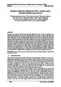
I. I NTRODUCTION The scaling of CMOS down to sub-micron regime has raised considerable concerns about the leakage power and variance tolerability of a circuit. With the increase of interconnect resistance as a result of scaling, signal delay through them also increases. Magnetic Quantum Cellular Automata (MQCA) is a potential candidate for addressing some of the aforementioned shortcomings in deep sub-micron design. By using the inherent properties of magnetic materials, MQCA has demonstrated liable logic circuit performance at room temperature. Recent developments in Spin Transfer Torque (STT) induced switching in Magnetic Tunnel Junctions (MTJs), a multi-layer Spintronic device, make them promising candidates as constituent elements in MQCA architecture. Their unique property to be switched with the application of a suitable current can be utilized for feeding the inputs to the architecture. High tunnel magnetoresistance (TMR), indicating the resistance difference between logic 0 and 1 states, observed in certain classes of MTJs increases the sense margin of their read circuitry. To our knowledge, we are the first to utilize the dipolar coupling between the free layers of neighboring MTJs to perform logic computation (see Fig. 1) over and above read-write necessity. We have performed a multi-layer micromagnetic simulation of a majority AND operation (see Fig. 2 using LLG simulation suite [1], MTJs were separated by 20nm). Note that the coupling was already known to the memory community but was treated as a hindrance to the memory density. These J.Das, S. Rajaram and S.Bhanja are with Electrical Engineering Department, University of South Florida, Tampa, FL S.M.Alam is Senior Member of Technical Staff in Everspin Technologies, Texas
(a)
(b)
Fig. 1. Spintronic devices as basic computing elements; (a) antiferromagnetic coupled wire, ferro-magnetic coupled wire (b) majority AND and OR implementation
reliable properties justify the use of MTJs as elements for nonvolatile logic computation in hybrid CMOS-MQCA structures with zero static power. In this paper, we have explored a novel MQCA architecture using a multi-layer Spintronic device that offers us better controllability on the cells of the architecture. We have introduced logic computation through dipolar interaction between the free layers of neighboring Spintronic devices in conjunction with STT induced clocking. In addition to designing the fundamental operations, such as input, output, and clocking, we have developed the necessary Spintronic device model to enable circuit level simulation of any logic function using existing CAD infrastructure. Rest of the paper is organized as following: Section II reviews the prior work in conventional MQCA based logic architecture and computational techniques. Our proposed Generic Regular Hybrid CMOSMQCA architecture, implementing complete state-full logic with co-existent memory and computation ability within cells, is described in Section III. Input scheme to the hybrid CMOSMQCA architecture using STT induced write operations is presented in Section IV. A novel differential sensing scheme for the MQCA outputs with high tolerance to variability is proposed in Section V. The read circuit, performing a low power non-destructive sensing, is designed and simulated in 22nm predictive CMOS technology [2]. Section VI discusses the STT induced clocking technique introduced in our architecture to aid state propagation between neighboring cells. A Verilog-A model of the Spintronic device cell is designed and discussed in Section VII. This is the first reported model to our knowledge to emulate the interaction among the neighboring Spintronic cells using a Finite State Machine (FSM), and at the same time, enabling write, read, and clocking of an individual cell fully utilizing the underlying physics. Finally, Section VIII
B
Z
C
B
A C A
Majority logic AND
Z B_
Word Line
2
Variability reduction S_
Horizontal Wire
Output Complement
F1
Vertical Wire
Majority logic OR
A
S_
Differential Output Generator
F3
(a)
(b)
substantiates our claims of design modularity, energy, and area optimization through supporting simulated and computed data. The novelty of our work lies in 1) proposing a hybrid CMOS-MQCA architecture that enhances modularity and introduces cell selectivity in clocking. 2) integrating 22nm CMOS with multi-layer Spintronic devices to realize the hybrid architecture using optimum number of metal layers. 3) proposing a spin-induced clocking where a cell is clocked by a short positive voltage pulse needed to drive the cell to precision state. The computing occurs postprecision. 4) using Spin Transfer Torque induced input writing and leveraging from MQCA architecture to obtain variability-tolerant differential outputs for nondestructive sensing 5) a Verilog-A model, for physics-based characteristics of the Spintronic cell, integrated with an FSM to model the dipole neighbor interaction. II. R EVIEW
OF
MQCA
Traditionally, MQCA comprises of a matrix of single layer permalloy disks or nanomagnets; each exhibiting singledomain behavior. An anisotropy in the shape of these magnetic cells gives them an energetically favorable direction of magnetization along their easy axis or largest dimension. The hard axes of the cells are along their shorter dimensions and contribute to the energy maxima in their energy landscape [3]. The two distinct magnetic orientations of the cells are suitably used in representing logic 0 and 1 in circuit operation. The magnetization of the cell can be switched between these two energy minimum states through suitably applied external fields. Furthermore, dipolar interaction between multiple neighboring cells also influences the final state. Once the cell switches to one of the energetically favorable magnetization
Majority logic AND
Horizontal Wire
S
B
Fig. 2. Micromagnetic simulation output, using LLG simulation suite, of a majority AND gate implemented using MTJs as computational elements. A and B are the inputs to the gate while C is the output. In (a) A and B are written to logic’1’ (+X direction). (b) A and B are written to logic ’0’ (-X) and ’1’ (+X), respectively. Mx , My are the in-plane magnetic moments per unit volume of the output cell C. Initially, the magnetization of the cell C is set along the ’Y’ axis, emulating the Clocked State of the cell as discussed in Section VI. The output cell C finally settles down under the influence of the input cells with its magnetization pointing along the +X direction in (a) and -X direction in (b). Note: Mx settles to a non-zero value while My settles down to zero indicating that the cell C has settled to one of its energy minimum state.
S_
Vertical Wire
F2
Source Line Bit Line
Horizontal Wire A_
S
Output
S
Variability reduction
Fig. 3. Generic Logic Brick for hybrid CMOS-MQCA architecture. Vertical word lines connect to all transistor gates in a column. Every row has a common bit line and source line.
direction, it retains its state until the next clock signal is applied to it. Various experimental demonstrations of logical components like majority [4], NAND/NOR [5], AND/OR [6] have been presented for MQCA logic. Performing the fundamental operations in MQCA array, such as clocking the cells for state propagation, supplying inputs, and sampling computed outputs, for any complex logic implementation is a challenge due to power consumption and difficulty of integration of the underlying circuits. Clocking the magnets for perfect ordering is in general performed by field-induced clocking [7], [8], [9], [10] except in the experimental demonstration in [6] that uses a rotating magnetic field. Magnitude of current required in these clocking schemes, to generate a high enough magnetic field, is high, in the order of milli − Amperes. Most of prior work have reported static inputs and outputs observed through magnetic force microscopy. Recently, MQCA systems were driven by on-chip input field current [11] where 680 mA were reported for an easy axis to easy axis switching (not using clock). The experimental read-out [12] was shown by trapping domain wall of a neighboring wire. In [13] researchers have experimentally demonstrated the feasibility of integrating MTJ with MQCA for resistance measurements. Alternate low power and better controlled input, output, and clocking schemes with back-end CMOS circuitry are the motivations of our work. There is a critical need to integrate input, output and clocking schemes with CMOS in order to realize a feasible future 2020 and beyond CMOS successor. In [14], authors have reported a non-volatile implementation of a hybrid CMOSMTJ full-adder using 34 transistors and 4 MTJs to perform the operation. The design requires storing one of the inputs to the adder in the MTJ while the other input is fed externally into the CMOS circuitry. However, this work suffers from many of the pitfalls of CMOS scaling due to physical electrical interconnects and offers much less flexibility in design. Contrary to prior work, our study is the first effort to use multilayer Spintronic devices as individual computing elements so that we can leverage from the Spin Transfer Torque (STT)
3
induced current switching and the integration with low power CMOS, at the same time using the interaction between devices to compute and propagate information. Most importantly, this work is the first step to offer localized control of individual elements of MQCA architecture. III. R EGULAR H YBRID CMOS-MQCA A RCHITECTURE Fig. 3 shows a novel hybrid CMOS-MQCA architecture implementing a half-adder logic function without the loss of generality. In this array the multi-layer Spintronic devices are arranged in a regular 2D grid. The horizontal and vertical pitch of the grid is constrained by the neighbor interaction from top, right, bottom and left. The 2D grid consists of an ensemble of majority logic blocks for AND/OR implementation, ferro-/anti-ferro interconnects and differential output generator blocks. The fixed cell in the majority logic is either set to logic 0 or 1 depending on AND/OR operation between the inputs to the majority logic. The presence or absence of a cell at a particular lattice site in the hybrid CMOS-MQCA architecture is determined by the underlying logical function. The cells in the 2D grid are broadly categorized into • Input cells - Cells with a nmos access transistor underneath them and marked in green (A, B and their complements) in Fig. 3. These cells accept inputs to the hybrid CMOS-MQCA architecture. They are never clocked. • Standard cells - Cells without access transistor and are connected directly across the bit and source lines through vias. These cells are marked in yellow in Fig. 3. All the standard cells in a row are clocked together. • Controlled cells - Cells with access transistors for selective clocking based on word line voltage. The controlled cells can be sub-categorized into Ordinary Controlled cells and Output cells marked in blue and red, respectively, in Fig. 3. The Output cells are subset of the controlled cells with additional connections to the readout circuit. The anti-ferromagnetic interconnects used for horizontal information propagation are realized through horizontal placement of Standard cells (horizontal wire in Fig. 3) with a pitch of 70nm. The ferro-magnetic interconnects are implemented through vertical placement of cells (vertical wire in Fig. 3) with a pitch of 120nm. The maximum number of cells in any interconnect is limited to 4 owing to existing clocking limitation [10]. Using the Differential Output Generator of the logic grid and its variability reduction feature, pairs of output cells and their complements are read simultaneously by the sensing circuitry discussed later in Section V. The sequence of rows or columns that needs to be selected for clocking is decided by row and column decoders, at the periphery of the circuitry, according to the logic to be performed. In Fig. 3, the architecture realizes the sum output S of a Half-Adder operation. The 2D grid of hybrid CMOS-MQCA array is suitable for fabrication with CMOS devices underneath the Spintronic devices. Fig. 4 shows a cross-section view along the easy axis of three neighboring cells. The cross-section view represents
Bit Line [Metal layer2] 120 120 Free Layer Pinned Layer
Source Line
70 Access Transistor
Free Layer
Free Layer
Pinned Layer
Pinned Layer
85 240
Via
Via
85
Metal layer1 Polysilicon
Via Access Transistor 110 All dimensions are in nm
Fig. 4. Cross-section view along the easy axis of three vertically located cells in a majority logic of the hybrid CMOS-MQCA architecture
three vertically located cells in the majority logic elements in Fig. 3. The free layers at the top are connected to individual bit lines located in metal layer 2. The pinned layer of the Input and Controlled cells are connected via metal layer 1 to the source of the access transistor beneath each. The Standard cells, on the other hand, have their pinned layer connected to a source line in metal layer 1. The poly gates of all the access transistors in a column are connected by a continuous poly line and can be strapped through a word line situated in metal layer 3 at the periphery of the array. In our study, the MQCA array is built of multi-layer Spintronic devices (MTJs) of 100nmx50nm footprint with 20nm horizontal and vertical spacing between neighbors. We first investigated which CMOS technology node is suitable for the hybrid CMOS-MQCA array. Spintronic device pitch requirement is restrictive to achieve neighbor interactions. Existence of only one nmos access transistor in a 2 x 2 cell area, as evidenced in Fig. 3, relaxes CMOS transistor pitch requirement (to achieve high W/L ratio for enhanced current drive and low ON resistance of the access transistors). The metal layer 1 pitch is maintained at 70nm while the metal layer 2 and metal layer 3 pitches are 120nm and 140nm each (see Fig. 4). The values are well within the specifications for 22nm CMOS technology node [15], thus substantiating our claim for the practical feasibility of the hybrid architecture at 22nm or below. IV. STT-I NDUCED I NPUT S CHEME The input to the generic array architecture is fed by writing an Input Cell comprising of an access transistor connected to the Spintronic device as shown in Fig. 5. Furthermore, all the Input cells are in the same column sharing a vertical word line. This enables providing all the inputs to the hybrid CMOSMQCA architecture in parallel at the start of the computation, thereby augmenting computation speed. All the inputs to the architecture are written in either one of the two initial and consecutive Global pulses, of positive and negative polarity, applied across the appropriate bit and source lines. The shared word line is raised high during both the occasions to select their access transistors. All the inputs that need to be written to AP state are written during the first pulse. The second pulse writes their complements. Eqn. 1 [16] determines the threshold value of switching current, Ic , for the cell while Eqn. 2 [17] calculates the duration τ of the current pulse,
4
ine
Bit L
Word Line Free Layer ayer ayer
Vdd
Vdd
M7
M5
Vdd
Vdd
Pinned Pi Pinn nned Lay nned Layer Layer er L ne e Li Sourcce
Φ3
M8
M6
Φ3
Source licon Access Transistor
Polysi
M9
Fig. 5.
X
Input Cell with access transistor
Y Eq
Φ2
M3
M4
Φ2
Comparator
A Φ1
(1)
M1a M1b
Φ1
B O/P Φ1 M M 2b 2a
Φ1
(2)
Fig. 6.
Sa_ Sb_
Readout circuitry for the CMOS-MQCA hybrid architecture.
1
Volts
where α is damping constant, µ0 is the permeability of free space, Ms is saturation magnetization of switching layer(free layer), V is the volume of the layer, η = p / (1+p2 ) for parallel-to-anti-parallel(P-to-AP) switching and η = p / (1-p2 ) for AP-to-P switching and p is the spin polarization, Hc is strength of in-plane magnetic anisotropy and the term 0.5.Ms is due to demagnetizing effect. γ is the gyromagnetic ratio while θ0 is the initial angle of magnetization between the free and the pinned layer. A current of magnitude IcAP or greater is passed from the bit line to source line (referred as positive current) to write the cell to anti-parallel (logic 1) state. A current of magnitude IcP or greater is passed from the source line to bit line (referred as negative current) to write the cell to parallel (logic 1) state. This is similar to writing conventional Spintronic devices [18].
Sa Sb
0.5 0 0
Pre-charge 1
2
phi3 Eq phi2
Sense 3
4
5
6
7
8
Time in s −−−−−> 0.8
Pre-charge
0.6 0.4 0
Sense
9 −9
x 10
1
Volts
required to effectively switch the cell. 2e Ic = .αµ0 V.Ms (Hc + 0.5.Ms ) hη 1 Ic π τ= . ln( ) αµ0 γMs I − Ic 2θ0
S S bar
455.41mV 1
2
3 433.7mV 4
5
Time in s −−−−−>
6
7
8
9 −9
x 10
V. TMR-BASED R EADOUT S CHEME
Fig. 7. Output Signals at node X and Y during Pre-Charge and Sensing Phases. Design implemented in 22nm predictive CMOS technology.
The reasonably high value of TMR in MgO based MTJs and their intrinsic dependence on bias voltage, gives a wide difference in the resistance of the cell between the parallel and anti-parallel states near zero-bias voltage [19]. This resistance difference is effectively utilized in reading the output of the MQCA architecture. Furthermore, we have proposed a novel Non-Destructive Low Power Differential ReadOut scheme leveraging the characteristics of the hybrid CMOS-MQCA architecture (in MQCA, we have bit and bit spatially adjacent) for a high tolerance to variability. The ReadOut circuit is illustrated in Fig. 6 . A symmetry is aimed among the transistors in the two arms of the circuit. The reading of the cell is carried out in two consecutive phases Pre-charge phase followed by Sensing phase as shown in the simulated waveforms Fig. 7. (M1a , M1b )and (M2a , M2b ) are access transistors of the output cells Sa ,Sb and their complements S a and S b , respectively. The access transistors remain on (φ1 = 1) during the entire read operation. During the Pre-charge phase, the φ2 signal is pulled low thereby turning off transistors M3 and M4 . The active low signal φ3 is pulled down to assist in fast pre-charge of the nodes X and Y to a potential Vdd . Signal Eq is raised high to equalize nodes X and Y through transistor M9 . During the sensing phase, φ2 is raised to a low voltage, say Vread , for applying a low voltage bias on the MTJs. With Eq = 0 and φ3 = 1, voltage differences start to grow at nodes X and
Y due to differential current from the complementary output states. The Comparator senses the potential across the nodes X and Y and accordingly the output O/P is made high or low. The key characteristics of our Readout schemes are: • Differential Output Reading: This technique utilizes the inherent property of MQCA architecture to readily produce the complement of a bit through anti-ferromagnetic coupling. • Low Power Non-destructive read: In order to read the contents of the Output Cells a very small current, in the range of 4-5 µA, is supplied to the cells. This ensures reading the cells at very low voltage bias, thus facilitating the effective utilization of high TMR for the sensing operation. A low read current through the cells rules out any possibility of their switching during Read. • Variability Tolerance: In the nanometer regime, any variations that creep in the cell dimensions can have a profound impact on the cell parameters. We have proposed a Variability Tolerant Read Architecture by reading pairs of cells (Sa , Sb ) and their complements (S a , S b ) simultaneously as shown in Fig. 6. Sensing standard deviation is reduced by a factor of 1.4 compared to a simple differential approach. The area and temporal
5 Inputs Clock Clock Clock Outputs zone1 zone2 zone3
Tclk
B_ F1
A
Write Write AP P
VAP
0V Vclk
row5
A_ B row6 row4
T1 Clock
t=T1
Vclk 0V
F2
t = T3+δ
Clock
t = T5+δ
Clock
A
Stage 2
[0:1] C
A
D
Output
[0:1] C
[0:1]
Parallel logic 0
B D
Dual-bit magnetic port
[0:1] C
[0:1]
[0:1]
Input
Horizontal Information Propagation
Clock Zone2 Clock Zone3
T4
Stage 1
[0:1]
A_.B
Clock Zone1
t = T4+δ
Clock
B D
Anti-Parallel logic 1
[0:1]
[0:1]
B A
A_
T2
T3 0V
S
B
t = T2+δ
[0:1]
Input
t = 0 time (ns) Input
F3
row4
0V Vclk
S_
A
Clock Tclk- δ
Output
Cl ock and I nput
Voltage Pulse
Vclk
A.B_
row3
0V
1
I nput
Cl ock
Input
0 −1
0
Posi ti ve P ul se 0.5
1 Ne gati ve P ul se
2 P re c e ssi on
1.5
2.5
3
3.5
Time in s −−−−−>
−8
x 10
1
T5
Anti-Parallel(AP)
Port D
0V -VP
B_ row2 row3
Half-Adder
Swi tch Anti -Paral l e l 0.5 0
Parallel(P)
0.5
1
1.5
Port D
Clocked/Precession
cost associated with this improvement is minimal. VI. STT- INDUCED
CLOCKING
Contrary to field-induced clocking using overhead Copper (Cu) wires [7], we have proposed a novel way of clocking the cells in the array that provides us with better control and selectivity over the cells, thereby optimizing power and area. In a Spin Transfer Torque induced switching device, when a positive current flows through the device, the damping force acts in opposition to the spin transfer torque in the free layer [18], which is routinely used in oscillators. An appropriate choice of current can equalize the forces and take the device into Precession. Soon after the current is released, the device switches to the energetically favorable direction under the influence of any magnetic field external to the device. We have utilized this concept and implemented the STT-induced clocking mechanism for our cells in the hybrid CMOS-MQCA architecture. The cells in the body of the logic are clocked using a discretely progressing positive Precession pulse, applied in sequence across the selected source and bit lines (see Fig. 8). This pulse is preceded by the two Global Write Pulses applied indiscriminately to all the cells in the body of the logic. The two Global pulses (positive followed by negative), ensures that all the cells in the body of logic are switched to the Parallel or Logic ’0’ state at the start of computation. This time instant is labeled as T1 in Fig. 8. Next, the logic computation and propagation takes place with the help of the series of Precession pulses applied to rows of cells in the sequence of logic computation (see Fig. 8). The cells in the next clock zone are set to precession when the clock for the current zone is released so that the cell’s state is only influenced by neighbors in the previous clock zone. The scheme introduces selectivity into the architecture through two sets of cells - Standard cells and Controlled cells. In a horizontal wire once the clocking pulse is released, the anti-ferromagnetic coupling among the cells retains the
3
3.5 −8
x 10 Se ttl e d
S tage I I Cl ocke d
Swi tch Paral l e l 0
0.5
1
1.5
2
2.5
3
3.5
Time in s −−−−−>
1 Port D
Se ttl e d
2.5
Swi tch Anti -Paral l e l
0.5 0
Fig. 8. Spin Transfer Torque induced clocking in Half-Adder to compute output S. The various stages of computation are illustrated. δ is a small positive quantity.
Cl ocke d
2 Time in s −−−−−>
1
Time
S tage I
Swi tch Paral l e l 0
−8
x 10
Ou tp u t
Swi tch Anti -Paral l e l
0.5
Swi tch Paral l e l
Cl ocke d Se ttl e d
0
0
0.5
1
1.5
2
2.5
3
Time in s −−−−−>
Fig. 9. Information propagation in a Horizontal Wire as in the Verilog-A model; Simulated output behavior from Verilog-A model
clocked state until a change in the state of the wire’s input propagates down the wire by pushing the next cells off their precession state [10]. Cells in a vertical wire are clocked by applying separate voltage pulses across the source and bit lines of the rows constituting the wire. The clocking pulse for a vertical wire is released sequentially in the direction of information propagation. For a vertical wire the ferro-magnetic coupling opposes the precession state if the clocking pulse for all the cells are released simultaneously [10], therefore, mandating a sequential release of clock for a vertical wire. The information propagation in vertical wire takes place similar to horizontal wire. A Controlled Cell is clocked by selecting its access transistors while corresponding bit and source lines are pulsed. It heleps in selectively clocking cells in a row only when required, thus saving power. VII. S PINTRONIC D EVICE M ODEL FOR H YBRID CMOS-MQCA S IMULATION A Verilog-A model of the Spintronic cell that emulates the STT-induced switching and clocking behaviors as proposed in the paper is developed. In addition to physics-based equations for MTJ fundamental characteristics, such as critical switching current, voltage dependant state resistance and TMR, [16] [20] [19], our Verilog-A model is the first of its kind to emulate the dipolar coupling between the free layers of neighboring cells through a Finite State Machine (FSM). Fig. 9 depicts a cell’s interaction with its neighbors. The salient features of the model are outlined below: • A cell switches its state only under the influence of its immediate neighbors to its top, left, bottom and right. • The cell’s interaction with its neighbors is modeled through four dual-bit bi-directional magnetic ports A, B, C, and D as in Fig. 9.
3.5 −8
x 10
6
– One of the four ports serves as the output of the cell depending on the direction of information propagation. The output port declares the state of the cell - Parallel(00), Anti-parallel(11) and Clocked / Precession(10/01). – The other three magnetic ports serves as the inputs for the cell, and plays the deciding role in the cell’s state right after the cell is clocked. • When the state of a cell, under the influence of its neighbors, is undeterministic, the ferromagnetic coupling from top and bottom neighbors decides the cell’s state. • A cell when in clocked state is considered to have no influence on its neighbors. The influencing neighbors and the cell’s behavior under their influence is modeled through two types of cells • Horizontal Cell that emulates information propagation in horizontal direction using bitwise operation by D = B · C + A · (B ⊕ C) When made to simulate a horizontal wire, the top and bottom inputs to the cells are fixed to anti-parallel and parallel state or otherwise, so that each cell is influenced by only the neighbor to its left/right depending on the direction of information propagation to the right/left. • Vertical Cell similarly computes its state under the influence of its neighbors using bitwise operation by D = B · C + A · (B ⊕ C). The entire MQCA architecture can be realized using proper interconnects of the two types of cells. The details of the Verilog-A model and FSM algorithms are omitted from the paper due to space limitation. The model is thoroughly tested and verified using different voltage pulses and different combinations of inputs in Cadence design environment. The model will be freely available to the scientific community to assist in the simulation of hybrid CMOS-MQCA logic. VIII. P ERFORMANCE A NALYSIS The cell characteristics in the proposed hybrid CMOSMQCA architecture are summarized in Table. I along with switching, clocking or precession, and read current values and durations. The values are theoretically computed using Eqn. 1 and Eqn. 2 or simulated when appropriated (for e.g. read). With a resistance of 2K offered by the cell in the parallel state and a TMR of 100 for a MgO based MTJ cell, the anti-parallel state offers a resistance of 4K. A half-adder is designed within the specifications of the hybrid architecture. A full-adder is designed using the half-adder as modules. The full adder templates are then instantiated to develop a 8-bit ripple carry adder and a 8x8 array multiplier, thus supporting the modularity in design. Table II presents the delay, energy and area in the abovementioned circuits. The total energy consumed is computed using our proposed STT-induced clocking as well as fieldinduced clocking techniques for comparison. A 4mA current (tc lk = 10ns) [7] is assumed for field-induced switching. Table ?? validates our claim of STT-induced clocking as an energy efficient clocking technique over traditionally used field-induced clocking for logic computation along with high
TABLE I C ELL D IMENSIONS AND C URRENT S PECIFICATIONS
100x50x2 nm3 70nm 120nm Current (µA) 320
Cell Dimension Horizontal pitch Vertical pitch Operation Write (P → AP ) Write (AP → P ) Clocking (P → AP → P recession) Reading (Non-destructive)
P
→
Time (ns)
160 267
7.6 (twAP ) 7.6 (twP ) 5 (tclk )
10
4
TABLE II D ELAY AND E NERGY COMPARISON IN VARIOUS L OGIC C IRCUITS IN H YBRID CMOS-MQCA A RCHITECTURE
Logic function
Delay (ntclk +mtw )
Energy (Fieldinduced Clocking) 287pJ 1015pJ 32.5nJ
Area [µm2 ]
4+2 8+2 256+2
Energy (STTinduced Clocking) 78.5pJ 278pJ 8.9nJ
Half-Adder Full-Adder 32-bit Ripple Carry Adder 8x8 array multiplier
60+2
15.2nJ
57nJ
95.97
0.41 1.9 60.8
selectivity of cells in the body of the logic. A 70 − 75% reduction in energy consumption is observed using STTinduced clocking. Furthermore, as seen from Eq. 1, the switching current decreases in proportion as the Spintronic devices (MTJs) are scaled down. So does the energy consumption of the circuit. But the reverse effect occurs for field-induced clocking with scaling [21] that is used in the most of the prior work discussed in Section II. IX. C ONCLUSION This work highlights the selectivity of cells offered and the power improvement through STT-induced clocking in a novel hybrid CMOS-MQCA architecture using multi-layer Spintronic devices (MTJs). The feasibility of the architecture with 22nm or below CMOS technology is studied. The fast, low power and non-destructive Readout circuit demonstrates robustness against variability by leveraging inherent properties of the hybrid CMOS-MQCA architecture. The modularity of design block heleps in the realization of larger circuits. With the scaling of underlying CMOS, the overlying Spintronic cell dimensions will reduce leading to lower switching current and overall reduction in computation energy in future. A VerilogA model of the Spintronic device has been developed and is available for others to explore novel hybrid CMOS-MQCA circuits. R EFERENCES [1] “Llg micromagnetic simulator.” http://llgmicro.home.mindspring.com/.
7
[2] “Predictive technology model.” http://ptm.asu.edu/. Downloaded in 2010. [3] G. Csaba, P. Lugli, A. Csurgay, and W. Porod, “Simulation of power gain and dissipation in field-coupled nanomagnets,” Journal of Computational Electronics, vol. 4, no. 1, pp. 105–110, 2005. [4] A. Imre, G. Csaba, L. Ji, A. Orlov, G. Bernstein, and W. Porod, “Majority Logic Gate for Magnetic Quantum-Dot Cellular Automata,” 2006. [5] R. Nakatani, H. Nomura, and Y. Endo, “Magnetic logic devices composed of permalloy dots,” in Journal of Physics: Conference Series, vol. 165, p. 012030, IOP Publishing, 2009. [6] M. Niemier, E. Varga, G. Bernstein, W. Porod, M. Alam, A. Dingler, A. Orlov, and X. Hu, “Boolean logic through shape-engineered magnetic dots with slanted edges,” IEEE Trans. on Nanotechnology, 2010. [7] M. Niemier, M. Alam, X. Hu, G. Bernstein, W. Porod, M. Putney, and J. DeAngelis, “Clocking structures and power analysis for nanomagnetbased logic devices,” in Proceedings of the 2007 international symposium on Low power electronics and design, pp. 26–31, ACM New York, NY, USA, 2007. [8] A. Dingler, M. Siddiq, M. Niemier, X. Hu, M. Alam, G. Bernstein, and W. Porod, “Controlling magnetic circuits: How clock structure implementation will impact logical correctness and power,” in Defect and Fault Tolerance in VLSI Systems, 2009. DFT’09. 24th IEEE International Symposium on, pp. 94–102, IEEE, 2009. [9] C. Augustine, B. Behin-Aein, X. Fong, and K. Roy, “A design methodology and device/circuit/architecture compatible simulation framework for low-power magnetic quantum cellular automata systems,” in Proceedings of the 2009 Asia and South Pacific Design Automation Conference, pp. 847–852, IEEE Press, 2009. [10] D. Carlton, N. Emley, E. Tuchfeld, and J. Bokor, “Simulation Studies of Nanomagnet-Based Logic Architecture,” Nano Letters, vol. 8, no. 12, pp. 4173–4178, 2008. [11] M. Alam, M. Siddiq, G. Bernstein, M. Niemier, W. Porod, and X. Hu, “On-chip clocking for nanomagnet logic devices,” Nanotechnology, IEEE Transactions on, vol. 9, no. 3, pp. 348–351, 2010. [12] A. Orlov, A. Imre, G. Csaba, L. Ji, W. Porod, and G. Bernstein, “Magnetic Quantum-Dot Cellular Automata: Recent Developments and Prospects,” J. of Nanoelectronics and Optoelectronics, vol. 3, no. 1, pp. 55–68, 2008. [13] A. Lyle, J. Harms, A. Klemm, and J.Wang, “Incorporating magneto resistance into mqca logic,” in Annual Conference on Magnetism and Magnetic Material, 2010. [14] S. Matsunaga, J. Hayakawa, S. Ikeda, K. Miura, T. Endoh, H. Ohno, and T. Hanyu, “Mtj-based nonvolatile logic-in-memory circuit, future prospects and issues,” in Design, Automation Test in Europe Conference Exhibition, 2009. DATE ’09., pp. 433 –435, 2009. [15] “International technology roadmap for semiconductor,” 2009. [16] T. Moriyama, T. J. Gudmundsen, P. Y. Huang, L. Liu, D. A. Muller, D. C. Ralph, and R. A. Buhrman, “Tunnel magnetoresistance and spin torque switching in MgO-based magnetic tunnel junctions with a Co/Ni multilayer electrode,” Applied Physics Letters, vol. 97, pp. 072513–+, Aug. 2010. [17] L.-B. Faber, W. Zhao, J.-O. Klein, T. Devolder, and C. Chappert, “Dynamic compact model of spin-transfer torque based magnetic tunnel junction (mtj),” in Design Technology of Integrated Systems in Nanoscal Era, 2009. DTIS ’09. 4th International Conference on, pp. 130 –135, 2009. [18] D. C. Ralph and R. A. Buhrman, Concepts in Spin Electronics, ch. Spintransfer Torques and Nanomagnets. Oxford Science Publications, 2006. [19] S. Yuasa, T. Nagahama, A. Fukushima, Y. Suzuki, and K. Ando, “Giant room-temperature magnetoresistance in single-crystal fe/mgo/fe magnetic tunnel junctions,” 2004. [20] S. Zhang, P. M. Levy, A. C. Marley, and S. S. P. Parkin, “Quenching of Magnetoresistance by Hot Electrons in Magnetic Tunnel Junctions,” Physical Review Letters, vol. 79, pp. 3744+, November 1997. [21] I. L. Prejbeanu, M. Kerekes, R. C. Sousa, H. Sibuet, O. Redon, B. Dieny, and J. P. Nozires, “Thermally assisted mram,” Journal of Physics: Condensed Matter, vol. 19, no. 16, p. 165218, 2007.