International Journal of Computer Applications in Engineering Sciences [VOL I, ISSUE III, SEPTEMBER 2011]
[ISSN: 2231-4946]
Hybrid Resonant Inverter Fed Induction Heating Using Fuzzy Logic Based PWM Atanu Bandyopadhyay 1
Pradip Kumar Sadhu 2 Nitai Pal 3 Swaroop R. 4
1
Department of Electrical Engineering, Asansol Engineering College, Asansol – 713305, West Bengal, India, 2, 3 Department of Electrical Engineering, Indian School of Mines University, Dhanbad – 826004, Jharkhand, India, 4Department of Electrical and Computer Engineering, University of Nizwa, Sultanate of Oman. 2
[email protected],
3
[email protected],
Abstract-- The inverters are commonly used for medium power induction heating applications. In the process of induction cooking, a disc of metal is surrounded by a copper coil through which an alternating current is made to flow. The disc has a finite diameter and thickness. It is placed at a given distance from the coil and concentric to it. Secondary current is induced in the disc and this induced current circulates around the outer surface of the disc resulting heating effect. The switching is done at various frequencies to get energy efficient heating. In this paper switching is done using fuzzy logic controller to get the energy efficient heating. The fuzzy logic controller uses the error and the rate of change of error as input and the frequency is fed as output to maintain at the required temperature. The hardware system is developed and fabricated. The fuzzy logic controller is designed and simulated in MATLAB to get the switching frequency. In this paper a inverter where both series and parallel resonant circuits are used for an induction cooking-range with two hot zones. In order to minimize losses, switching is made at zero current crossover (ZCS). Keywords-- Induction Heating, Fuzzy Logic Controller, Hybrid Resonant Inverter, switching, cooking appliance.
I. INTRODUCTION Modern devices like MCT‟s make it easier to apply induction-heating technique[1, 2, 4] in kitchen cookingranges for domestic use. Induction heating technique in cooking-ranges is becoming a strong alternative to gas, normal electrical hotplates and microwave oven. As compared to dielectric heating as in microwave oven, the proposed technique of induction heating is more convenient and cost effective[3, 5]. For example, in microwave oven, food is cooked in a special nonmetallic bowel inside a closed chamber, while the proposed method would permit cooking using normal house-hold metal utensils like steel pan, pressurecooker, iron bowl etc leading to a lot of savings in cost of utensils. The proposed topology also possesses an unique advantage for Indian sub-continental style of cooking, in which for majority of recipe, it starts with
4
[email protected]
frying of foodstuff in vegetable oil in a metal pan[4, 8]. This art of cooking is quite possible in the proposed scheme while microwave oven does not permit frying or even handling the substances at the time of cooking. Besides, the proposed induction heating system is absolutely safe from shock hazard during cooking [3, 5, 6]. The induction-heating system is also extremely rugged because of absence of red-hot temperature in the induction coil resulting in no deterioration or aging of coil [7]. Besides, there is no conduction loss during transfer of heat from source to the cooking pan in induction-heating system [4, 8]. It is possible to get an efficiency of about 83.3 % to 93.5 % for each heating system. The induction heated cooking range was built and tested with and without cooking-pots. II. SELECTION OF MCT AS SEMICONDUCTOR SWITCH In the present scheme, the selection of MCTs over other conventional semiconductor switches (like Thyristors, BJTs, Power MOSFETs, IGBTs etc) has been guided by the following favourable conditions in respect of the former. A low forward voltage drop during conduction like normal thyristor. The normal thyristor is not a self turn off device but MCT is turned off by positive voltage pulse. So it has no requirement of commutation circuit. Fast turn-on time, typically 0.4 sec and fast turn-off time, typically 1.2 sec for an MCT of 500 V, 300 A. Low switching losses compared to other semiconductor switches. High power handling capacity like normal thyristors. High gate impedance which allows simpler design of drive circuit. MCT consumes very small power from control circuit for switching-on, since it is a voltage pulse driven switch. III. PRESENT SCHEME One hybrid resonant inverter consists of four semiconductor switches (MCT‟s) for each cookingrange. The switching frequency of present scheme lies between 25 to 34.48 kHz. The inverter is a combination of both series and parallel resonant circuits where the
320 | P a g e
Bandyopadhyay et. al.
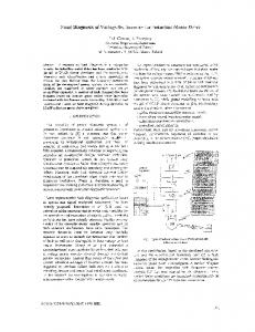
switching is made at zero current cross over (ZCS). Different control strategies have been discussed to show that an optimum concerning efficiency occurs when switching around the zero crossing of the parallel resonance circuit voltage. With the inverter implemented in an induction heating system, the total system efficiency (i.e. from the mains to the load) of around 88.2 % has been achieved. Discussions regarding detection of missing cooking pot and short circuit are included in later part of the paper. Fig. 1 shows a resonant inverter system for one hot plate. The mode of operation basically consists of interaction between two resonant circuits where the energy is transferred from the series resonant circuit (consisting of CR and L1) to the parallel resonant circuit (consisting of CR, RL and LR). By turning on one of the transistor pairs S1, S4 or S2, S3 a resonant current starts flowing through L 1 to CR and when this circuit current is zero the transistors are switched off. Hereafter the series resonant circuit is disconnected and the energy transferred to CR is now dissipated as heat in RL by the current flowing in the parallel resonant circuit. RL is mainly an equivalent resistance for the magnetic loss mechanism in the induction heating system and secondly it represents the ohmic resistance of the parallel resonant circuit components.[7] IV. FUZZY LOGIC SYSTEM In this induction heating system the input is the frequency for switching S1,S2,S3 and S4. The output is the heat generated. The output is also converted in the range [0-1] and is fed as input to the fuzzy system. The error is the difference between input and output which is calibrated to the range [-5,5]. This is fed to the fuzzy controller. The output of the FLC is the frequency which is given to the comparator where the square pulses are generated. These square waves are used to activate the switches S1-S4. S1, S4 and S2,S3 are connected together so that either of one combination will be turned ON. The pulses generated are stored in the figure 7,8. This is simulated in MATLAB in simulink as shown in the figure 6 [8,9]. In fuzzification error (e) and rate of change of error (de) are used as inputs. The error is divided in to various ranges in the range [-5, 5]. The e and de are categorized as NB (Negative Big) NM (Negative Medium) NS (Negative Small Z (Zero) and PS (Positive Small) PM (Positive Medium) and PB (Positive Big). Refer Figure 2 and 3.The defuzzification is also divided in to the ranges PVS (Positive Very Small) PS (Positive Small) PM (Positive Medium) and PB (Positive Big) and Positive Big (PVB). The defuzzification designed in MATLAB is shown in the figure 4. The Rule base which selects the output range for the corresponding input range is shown in the table I. For
321 | P a g e
example the first cell indicates that if the de is NB (Negative Big), and e is NB (Negative Big) then the output falls in the range PVB (Positive Very Big). It means that the frequency falls in the range PVB which is from 15 to 50 KHz. After selecting the range from rule base the defuzzifier identifies the output in this range. The output for every change in error (e) and the rate of change of error is shown in the figure 5. V. STRUCTURE OF LOAD CIRCUIT Using high power switching devices like thyristors, IGBTs, MCTs etc, the hybrid resonant inverter can be used in low, medium and high power induction heating applications. A thermal insulator is placed in between the cooking vessel and the heating-coil to protect the coil from over heating and also to support the vessel. A ferrite disc is often used to enhance the coupling but with an increase in cost. In order to obtain maximum coupling, the space between the vessel and the coil should be kept as small as possible. But at the same time this gap should be large enough for sufficient strength of support, insulation and airflow. The vessel must be made up of material for which the product of resistivity and relative permeability is high enough to yield an acceptable efficiency. Table-II represents efficiency of induction cooker for all the five different temperature sets and fig. 8 indicates the temperature response at each temperature set. Experimental Prototype has been developed. The assembly of induction coil (Litz Wire Coil / Pan-cake Coil) used for high frequency hybrid inverter fed induction cooker, is shown in figure 9. The assembly of one cooking zones out of two zones is shown in figure 10. VI. CONCLUSIONS The hard ware system is fabricated and tested for the efficiency at various frequencies and is found that the efficiency is maximum at 33 KHz. The Fuzzy Logic controller is designed in MATLAB and simulated for various error and the rate of change of error and the corresponding frequencies are fed to the MATLAB embedded function which gives the square pulses to switch the hybrid resonant inverter at various frequencies. Comparators are used to get the switching pulses for various frequencies. REFERENCES [1].
[2].
Pradip Kumar Sadhu, Narendranath Jana, Rupendranath Chakrabarti and Dilip Kumar Mittra “A Unique Induction Heated Cooking Appliances Range Using Hybrid Resonant Converter” – International Journal of Circuits, Systems and Computers, World Scientific, Volume 14, Number 3, June 2005, P.P. – 619-630. Sadhu P. K., Chakrabarti R. N., Chowdhury S. P. „An improved inverter circuit arrangement.‟ Patent No. 69/Cal/2001, Patent Office – Government of India.
Hybrid Resonant Inverter Fed Induction Heating Using Fuzzy Logic Based PWM
[3].
[4].
[5].
[6]. [7].
[8].
[9].
Sadhu Pradip Kumar, Chakrabarti R. N., Chowdhury S. P. „A cooking apparatus using high frequency induction heating.‟ Indian Patent No. 216361 (68/Cal/2001), Patent OfficeGovernment of India Dr. Pradip Kumar Sadhu, Dr. R. N. Chakrabarti, Dr. S. P. Chowdhury. „A new generation fluid heating using BJT and IGBT.‟ Journal of the Institution of Engineers (India) vol-82, March, 2002, pp 273 -280. Dr. Pradip Kumar Sadhu, Dr. S. K. Mukherjee, Dr. R. N. Chakrabarti, Dr. S. P. Chowdhury and Dr. B. M. Karan. „A new generation microprocessor based series resonant inverter for induction heating cooking appliances.‟ Industrial Engineering Journal, Navi Mumbai, vol XXX, no 9, September, 2001, pp 10 -15. J. P. Landis. „A static power supply for induction heating.‟ IEEE-Trans, IECI, vol.17 no. 4, September, 1970, pp 313-320. M. Nakaoka. „A Phase-difference angle control- mode PWM high-frequency resonant inverters using static inductiontransistors and thyristors.‟ Proceedings of IEEE-PESC 87, June1987, pp 674-681. Patyra, M.J. (1996), “Design consideration of digital fuzzy logic controller”, in Patyra, M.J. and Mlynek, D.M. (Eds), Fuzzy Logic: Implementation and Applications, Wiley, Chichester. Rao, D.H. and Saraf, S.S. (1996), “Study of fuzzification methods of fuzzy logic controller for speed control of a DC motor”, Proceedings of the 1996 International Conference on Power Electronics, Drives and Energy Systems, Vol. 2, pp. 7827.
Fig. 2 Fuzzification of Error
Fig. 3 Fuzzification of rate of change of error
Fig.. 1 Hybrid resonant inverter system for one cooking zone
322 | P a g e
Bandyopadhyay et. al.
TABLE I: RULE BASE
DE/E
NB
NM
NS
Z
PS
PM
PB
NB NM NS Z PS PM PB
PVB PVB PB PM PS PVS NS
PVB PB PM PS PVS NS NVS
PB PM PS PVS NS NVS NS
PM PS PVS NS NVS NS NM
PS PVS NS NVS NS NM NB
PVS NS NVS NS NM NB NVB
NS NVS NS NM NB NVB NVB
Fig. 4 Defuzzification of Frequency
Fig. 5 Error, Rate of Error Vs Frequency (Input Vs Output)
TABLE-II: EFFICIENCY - TEMPERATURE SET OF THE INDUCTION COOKER SYSTEM
Temperature Set Warm Set-I Set-II
323 | P a g e
Semiconductor Semiconductor Switch Time Period Switch ON-Time (s) OFF-Time (s) (s) 3 5 9
26 25 24
29 30 33
Frequency (kHz) 34.48 33.33 30.30
% Efficiency 83.3 84.6 93.5
Hybrid Resonant Inverter Fed Induction Heating Using Fuzzy Logic Based PWM
Set-III Set-IV Set-V
13 16 19
22 21 21
35 37 40
28.60 27.02 25.00
91.1 89.5 87.2
Fig. 6 Implementation of Fuzzy Logic to the Induction Heating System in Simulink.
Fig.7 Square pulses to Switch S1,S4
Fig. 8 Square pulses to switch S2,S3
324 | P a g e
Bandyopadhyay et. al.
Fig.9 Assembly of Induction coil
325 | P a g e
Fig. 10 Assembly of one cooking zones out of two zones