Engineering MECHANICS, Vol. ... real system and model verification can be tested online. .... Figures show the piston position time course for each piston.
Engineering MECHANICS, Vol. 16, 2009, No. 4, p. 287–296
287
HYDRAULIC ARM MODELING VIA MATLAB SIMHYDRAULICS Stanislav Vˇechet, Jiˇr´ı Krejsa* System modeling is a vital tool for cost reduction and design process speed up in most engineering fields. The paper is focused on modeling of hydraulic arm as a part of intelligent prosthesis project, in the form of 2DOF open kinematic chain. The arm model combines mechanical, hydraulic and electric subsystems and uses Matlab as modeling tool. SimMechanics Matlab extension is used for mechanical part modeling, SimHydraulics toolbox is used for modeling of hydraulic circuit used for actuating corresponding mechanical components. Interconnection between the subsystems is essential issue, as it is surprisingly not a straightforward task in Matlab/Simulink, despite the fact that each toolbox works well if used in stand alone mode. The model is verified with the physical model of hydraulic arm actuated by micro electro-hydraulic components. Keywords : simulation modeling, hydraulics, SimHydraulics, SimMechanics, Matlab
1. Introduction The issues solved in this paper arose during the project of intelligent prosthesis focused on providing active assisted motion for the patients with posttraumatic states concerning joint structures. The joint project of Institute of Thermomechanics, CAS and Traumatology department of University Hospital in Olomouc requires reliable mechanical structure actuated with sufficient forces and precision. To test the control algorithms, actuators and mechanical components, the model of mechanical arm with hydraulic actuators was developed both as simulation model and real physical model. The simulation model requires modeling both the mechanical and hydraulic subsystems and fusion of those subsystems to obtain corresponding overall model. There are number of approaches to simulate the combined mechanical – hydraulic – electric systems, both simulation software specific and independent (e.g. [1], [2]). One of the software packages popular among engineers is Matlab. Most of the models are being developed with basic Matlab and its dynamic simulation extension Simulink, see e.g. [3]. Several extensions of Matlab recently added to the system enable to model kinematics and dynamics of mechanical components using SimMechanics, hydraulic components using SimHydraulics, planetary gears and similar components using SimDriveline [4]. Using these extensions the engineers obtain powerful tools for mechanical/hydraulic systems modeling. In order to speed up the design process and test control algorithms the simulation model is advantageous, however the model must correspond to the real system. Therefore we simultaneously built the physical model of hydraulic arm with two actuators and simulation * Ing. S. Vˇechet, PhD., Ing. J. Krejsa, PhD., Institute of Thermomechanics AS CR, v.v.i., Centre of Mechatronics – Brno branch office, Technick´ a 2, 616 69 Brno
288
Vˇ echet S. et al.: Hydraulic Arm Modeling via Matlab SimHydraulics
model, which uses SimMechanics [5] and SimHydraulics [6] to model corresponding subsystems. The interconnection and cooperation of those subsystems is however not as trivial task as we expected. The real system uses micro electro-hydraulic parts and is controlled from standard desktop computer, therefore the simulation model can run in real time mode together with the real system and model verification can be tested online. Each aspect of presented system is discussed in greater detail in separate chapters. Chapter 2 describes the real hydraulic arm, mechanical system, hydraulic circuit and connection with PC. Chapters 3 and 4 discuses simulation models of mechanical and hydraulics parts. The connection between models is shown in chapter 5. The comparison of model simulation and real arm is analyzed and discussed in chapter 6. 2. Design of physical hydraulic arm model Mechanical construction of hydraulic arm is based on basics kinematics model shown on Figure 1. Lower arm (body 2) is connected to base in rotary joint A, upper arm (body 3) is connected to lower arm in rotary joint D. Both arms are driven by independent actuators, lower actuator is connected to base frame in joint E, upper actuator drives upper arm relative to its lower counterpart. This simple 2D model has two degrees of freedom and while simple it corresponds to the real prosthesis motion.
Fig.1: Kinematic model of hydraulic arm
Both arms are actuated using hydraulic circuit that is built from non-standard micro hydraulics components. Actuators are equipped with position sensor feeding the controllers with feedback data. Whole system is controlled from ordinary desktop computer that controls the electronic controller of pump electric drive and servomechanisms of distributor valves. The actuators therefore act as electro-hydraulic converters. Valve servodrives, pump controller and position sensors communicate with computer through custom built electronic modules connected to PC via serial line. The position sensors are mounted on the pistons and they measure the relative position of the rod. Therefore it is necessary to calibrate the sensors after each startup sequence. We use magnetic sensors MLFK 08 provided by Baumer company. Used sensors have 0.07 mm accuracy and measuring frequency up to 160 kHz. Sensors are relatively small (width 15 mm, housing length 45 mm) which was one of the reasons to use it.
289
Engineering MECHANICS
Essential technical parameters of hydraulic components used for the mechanism in question are summed up in Table 1, Figure 2 shows overall view of the physical model with some of the details.
Fig.2: Hydraulic arm (left) and detailed view to hydraulic piston (right) mounted on arm prototype
Hydraulics pressure Pump capacity Tank volume Piston stroke Force (pressure 1 MPa) Piston speed Arm length Overall weight Supply voltage
0.36 MPa 180 cm3 /min 45 ml 110 mm 153 N 0.03 m/s 1m 5 kg 8.4 V
Tab.1: Hydraulic arm parameters
3. Model of mechanical subsystem The model of mechanical subsystem of hydraulic arm was created with SimMechanics Matlab extension. SimMechanics is an efficient tool for modeling and simulating mechanical systems in Matlab/Simulink environment. The simulation model incorporating the geometry of physical model is overviewed on Figure 3. SimMechanics toolbox uses block modeling to model bodies, joints and corresponding inputs and outputs, with each block defining the physical properties such as mass and moment of inertia, possible motion in joints, etc. Sensor blocks return the motion variables values (motion outputs), actuator blocks represent the
290
Vˇ echet S. et al.: Hydraulic Arm Modeling via Matlab SimHydraulics
inputs. Modeling of both arms and its rotary joints is straight forward. As both arm bodies are actuated by linear hydraulic pistons, these actuators are represented in the mechanical part of the model by prismatic joints.
Fig.3: Overall model of hydraulic arm in SimMechanics
Prismatic joints are used in connection to the hydraulics model. They can be actuated by motion and also provide necessary information about position reached by the piston. On Figure 4 one can see the detailed view of incorporating the prismatic joint to the arm model. Sensor block returns the kinematic variable regarding the joint (position, velocity, acceleration), actuator block enables to set those variables directly into the joint (kinematic excitation), or common excitation using forces can be used. The overall view of complete model of the arm kinematics is shown on figure 5. Such model can be used for basics simulations for testing purposes without any connection to hydraulic subsystem. The joints and bodies labeling on following figures corresponds to one used in Figure 1.
Fig.4: Detailed view to a part of the model with prismatic joint which is used instead of hydraulic piston in kinematics model
Table 2 provide list of used blocks with major settings, which was used during designing presented kinematics model. 4. Simulation model of hydraulic circuit Hydraulics subsystem is modeled via Matlab SimHydraulics toolbox. This toolbox is relatively new in Matlab extensions family and therefore at the moment it lacks extended documentation regarding user specific problems. However, it t is relatively easy to implement a model of plain operating hydraulic circuit. Basically, one of the simplest hydraulic circuits consists of one hydraulic cylinder controlled by 4 or 5 way proportional electric valve. Presented hydraulic arm is actuated by two hydraulic pistons and each piston has its own
291
Engineering MECHANICS
Fig.5: Overall view to complete kinematics model Block name Body – upper arm Body – lower arm 4× other bodies (represents two pistons) 6× revolute joints 2× prismatic joints 2× joint sensors 2× joint actuator
Major parameters Mass = 0.5 kg Mass = 0.5 kg Mass = 0.1 kg Rotation in Z axis Translation in X and Y axis Arm position measuring Actuated with position
Tab.2: List of important blocks with their settings
electric control valve. The need to control hydraulic pistons from PC demands the using of proportional electric valves. Plain hydraulic circuit without electric lines is shown on Figure 6, it consists of two hydraulic cylinders (1.0 and 2.0) with electric control valves (1.1 and 2.1) and hydraulic pump (0.1) with by-pass valve (0.2). This circuit with all necessary components has to be modeled in Matlab. Building a hydraulic circuits in SimHydraulics has similar rules as SimMechanics despite the fact that these rules are slightly different from standard hydraulics schemes. Model of
Fig.6: Real hydraulic circuit block diagram
292
Vˇ echet S. et al.: Hydraulic Arm Modeling via Matlab SimHydraulics
hydraulic circuit is presented on Figure 6 and the reader can compare it with corresponding SimHydraulics scheme on Figure 7. Its obvious that building a simulation model in Matlab is a bit more complicated then building the same model from real components. Note that Figure 6 shows both pistons, in comparison with single piston shown on Figure 7.
Fig.7: Overall view to hydraulics model of one piston using Matlab SimHydraulics
Especially the proportional control of each valve wasn’t so straightforward. In real device, the proportional valve is used to control the continuous flow through the circuit and is realized via solenoid switch. The corresponding model in SimMechanics is realized by 4-way valve, 3-position valve actuator and few others necessary components. The proper settings of these blocks were found experimentally with reference to the real hydraulic arm. Table 3 shows a list of important blocks with adjusted parameters. Block name Double Acting Hydraulic Cylinder
4-Way Directional Valve 3-Position Valve Actuator Ideal Hydraulic Pressure Source
Major parameters Piston area A = 0.133×10⁻³ m2 Piston area B = 0.113×10⁻³ m2 Piston stroke 0.11 m Valve maximum opening = 1×10⁻³ m Nominal signal value = 24 0.36 MPa
Tab.3: Major parameters of the most important blocks
Described hydraulics model was successfully used for initial tests, in which the basic functionality of model was tested. Figure 8 shows the control of hydraulic piston position. It shows how the piston (rod) position depends on valve position (it means the direction in which the valve is opened – plus, minus, closed), as it is the basic operation during control of the direction of piston movement and its position. 5. Putting mechanics and hydraulics together The connection between two presented models representing the mechanical and hydraulic subsystems was not as straightforward as we expected. In first experiments we used kine-
Engineering MECHANICS
293
Fig.8: Basics simulation of hydraulic piston without connection to the kinematics model
matics excitation given by the piston motion for mechanism movement and force sensors as feedback to the hydraulic cylinder. This connection can be easily managed as shown above. However, this is not a proper solution, and it only works for very simple models. Once hydraulic circuit is more complex than simple piston, the model becomes numerically unstable with subsequent Matlab crashes. The proper way to connect the subsystems is to use special block called Prismatic Translational Interface. This block substitutes previously discussed relationship (with kinematics excitation and forced feedback). It connects a prismatic primitive in the joint to any two mechanical translational nodes and exchanges translational kinetic energy without loss. Figure 9 shows how to use this block. Practical application of Prismatic Translation Interface block is clearly shown on Figure 10. There you can see that this block is connected in parallel to the Double-Acting Hydraulic Cylinder and the output is connected to the kinematics model in higher level, which is shown on Figure 11.
Fig.9: Detailed view to Prismatic Translational Interference, MTR stands for Mechanical Translational Reference
294
Vˇ echet S. et al.: Hydraulic Arm Modeling via Matlab SimHydraulics
Fig.10: Hydraulics part in which the Prismatic Translational Interface is implemented
Complete model of hydraulic arm is shown on Figure 11. One can see that the connection between hydraulics and kinematics model is made via prismatic joint which is connected to the hydraulics submodel (denoted as upper/lower hydraulic piston in Figure 11). The internal structure of these submodels was discussed above.
Fig.11: Overall view to high control level with both kinematics and hydraulics toolboxes together
Engineering MECHANICS
295
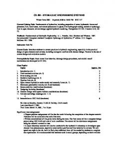
6. Experimental Results To verify the credibility of the approach, the simulation model of hydraulic arm was tested together with the real hydraulic arm in our laboratory. The tests were focused on basic verification of the model, so first experiments tested the ability of SimHydraulics to simulate appropriate behaviour of real device. The basic task is a performance of simple rod movement from one limit position to the other, within rod outer limits. In real device this movement is realized with fully opened (maximal flow) control valve. The model of hydraulic arm presented above was tested for such a case. In both model and real device the control valve was fully opened and we compared the piston position over time. The experiments showed the basic differences in behaviour of the model and real arm. Figures 12 and 13 present the comparison of simulation model output with real device measurements. Figures show the piston position time course for each piston. Thus we can observe the difference between upper and lower piston and also between movement directions.
Fig.12: Simulation model of lower piston in comparison with real device
Fig.13: Simulation model of upper piston in comparison with real device
As one can see, the behaviour of tested model is in reasonably good correspondence with the real device. The largest difference is in movement of lower rod before it reaches the final position. Generally, the differences between model and real device are unavoidable, as there
296
Vˇ echet S. et al.: Hydraulic Arm Modeling via Matlab SimHydraulics
is a number of model parameters which are not known precisely. For example the rotary joints are modeled as ideal joints, the friction within pistons is neglected, etc. Moreover, the precision of real hydraulic circuit, together wit relative position sensor is not ideal as the real arm consists of low cost components. In spite the differences, we found the model to be close enough to reality to be utilizable in further development of intelligent prosthesis prototype. 7. Conclusions Presented modeling method was successfully tested with hydraulic arm which serves as a testing device for basics research in intelligent prosthesis development. We have presented an approach to modeling complex system which combines two different sub-systems : hydraulics and mechanics. Matlab extensions SimMechanics and SimHydraulics were used together as main simulation tool. Successful cooperation of models designed in these two simulation tools was accomplished via block named Prismatic Translation Interface. We included the initial test of the model versus real circuit. The test was designed to compare the output of simulation model with the measurement on real device performing the simple motion. This motion arises from basic task required from such devices: moving from one limit position to the other. We have shown that the behaviour of presented model is in reasonably good correspondence with the real device and therefore the using of discussed modeling tools is perspective for future applications. Acknowledgement This paper was written with support of the pilot project 920040 (The development of mobile actuated elbow orthosis) in the frame of research project AV0Z20760514. References [1] Papadopoulos E., Sarkar S.: On the Dynamic Modeling of an Articulated Electrohydraulic Forestry Machine, Proceedings of the 1996 AIAA Forum on Advanced Developments in Space Robotics, Madison, WI, USA, 1996 [2] Ziaei K., Sepehri N.: Modeling and identification of electrohydraulic servos, Mechatronics 10, pp. 761–772, 2000 [3] Qiu H.C., Zhang Q., Reid J.F., Wu D.: Modelling and simulation of an electrohydraulic steering system, International Journal of Vehicle Design 2001 – Vol. 26, No. 2/3, pp. 161–174 [4] Prabhu S.M.: Model-Based Design for Off-Highway Machine Systems Development, in proceedings of SAE 2007 Commercial Vehicle Engineering Congress & Exhibition, 2007 [5] The MathWorks Inc.: SimMechanics User’s Guide, Version 2.6, The MathWorks Inc., Natick, MA [6] The MathWorks Inc.: SimHydraulics User’s Guide, Version 1.2, The MathWorks Inc., Natick, MA
Received in editor’s office : May 22, 2009 Approved for publishing : August 20, 2009