I/O Device Performance. • Primary characteristic. • Data rate (bandwidth). •
Latency is really only an issue for disk. • Contributing factors. • Partner: humans
have ...
This Unit: I/O Application
• I/O system structure
OS
CIS 501 Introduction to Computer Architecture
Compiler CPU
Firmware I/O
CIS 501 (Martin/Roth): I/O
Gates & Transistors
1
Readings
• Device characteristics • Disks
• I/O control
Memory Digital Circuits
Unit 5: I/O
• Devices, controllers, and buses
• Polling and interrupts • DMA
CIS 501 (Martin/Roth): I/O
2
One Instance of I/O
• H+P
CPU
• Chapter 7.1-7.5, 7.7, 7.10, 7.14-16
I$
• Have briefly seen one instance of I/O • Disk: bottom of memory hierarchy
D$ L2
Main Memory
Disk CIS 501 (Martin/Roth): I/O
3
CIS 501 (Martin/Roth): I/O
4
A More General/Realistic I/O System
I/O Device Performance
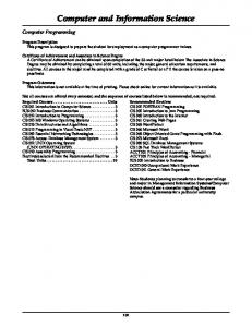
• A computer system
• Primary characteristic
• CPU/Memory: connected by memory bus • I/O peripherals: disks, input devices, displays, network cards, ... • With built-in or separate I/O (or DMA) controllers • All connected by a system bus CPU Cache
CPU Cache
Memory
DMA
Partner
I? O?
Data Rate (KB/s)
Human
Input
0.01
Mouse
Human
Input
0.02
Speaker
Human
Output
0.60
Printer
Human
Output
200.00
Display
Human
Output
240,000.00
Modem
Machine
I/O
8.00
Ethernet card
Machine
I/O
10,000.00
NIC
Disk
Machine
I/O
10,000.00
5
CIS 501 (Martin/Roth): I/O
I/O ctrl
Memory kbd
Disk
display
• Partner: humans have slower data rates than machines • Input/output/both Keyboard
“System” (I/O) bus
DMA
• Contributing factors Device
bridge Memory bus
• Data rate (bandwidth) • Latency is really only an issue for disk
CIS 501 (Martin/Roth): I/O
I/O Devices: Mouse, Keyboard, Display
6
I/O Device: Disk
• Many I/O devices have low performance needs
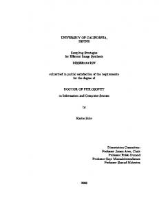
platter
head
• Disk: like stack of record players • Collection of platters • Each with read/write head
• Keyboard
• Platters divided into concentric tracks
• 1 B/key * 10 keys/s = 10 B/s
• Mouse
sector
• 2 B/transfer * 10 transfers/s = 20 B/s
• Display
• Head seeks to track • All heads move in unison
• Each track divided into sectors • More sectors on outer tracks • Sectors rotate under head
• 4 B/pixel * 1M pixel/display * 60 displays/s = 240M B/s
• Controller track
CIS 501 (Martin/Roth): I/O
7
CIS 501 (Martin/Roth): I/O
• Seeks heads, waits for sectors • Turns heads on/off • May have its own cache (a few MBs) • Exploit spatial locality 8
Disk Parameters
Disk Latency
Seagate ST3200
Seagate Savvio
Toshiba MK1003
Diameter
3.5”
2.5”
1.8”
Capacity
200 GB
73 GB
10 GB
7200 RPM
10000 RPM
4200 RPM
8 MB
?
512 KB
2/4
2/4
1/2
8 ms
4.5 ms
7 ms
150 MB/s
200 MB/s
200 MB/s
58 MB/s
94 MB/s
16 MB/s
ATA
SCSI
ATA
Desktop
Laptop
iPod
RPM Cache Discs/Heads Average Seek Peak Data Rate Sustained Data Rate Interface Use
• Newer from Toshiba • 0.85”, 4 GB drives, used in iPod-mini CIS 501 (Martin/Roth): I/O
9
• Disk read/write latency has four components • Seek delay (tseek): head seeks to right track • Average of ~5ms - 15ms • Less in practice because of shorter seeks) • Rotational delay (trotation): right sector rotates under head • On average: time to go halfway around disk • Based on rotation speed (RPM) • 10,000 to 15,000 RPMs • ~3ms • Transfer time (ttransfer): data actually being transferred • Fast for small blocks • Controller delay (tcontroller): controller overhead (on either side) • Fast (no moving parts) CIS 501 (Martin/Roth): I/O
10
Disk Latency Example
Disk Bandwidth: Sequential vs Random
• Example: time to read a 4KB page assuming…
• Disk is bandwidth-inefficient for page-sized transfers
• 128 sectors/track, 512 B/sector, 6000 RPM, 10 ms tseek, 1 ms tcontroller • 6000 RPM ! 100 R/s ! 10 ms/R ! trotation = 10 ms / 2 = 5 ms • 4 KB page ! 8 sectors ! ttransfer = 10 ms * 8/128 = 0.6 ms • tdisk = tseek + trotation + ttransfer + tcontroller = 16.6 ms • tdisk = 10 + 5 + 0.6 + 1 = 16.6 ms
• Sequential vs random accesses
• Random accesses: • One read each disk access latency (~10ms) • Randomly reading 4KB pages • 10ms is 0.01 seconds ! 100 access per second • 4KB * 100 access/sec ! 400KB/second bandwidth
• Sequential accesses: • Stream data from disk (no seeks) • 128 sectors/track, 512 B/sector, 6000 RPM • 64KB per rotation, 100 rotation/per sec • 6400KB/sec ! 6.4MB/sec
• Sequential access is ~10x or more bandwidth than random • Still no where near the 1GB/sec to 10GB/sec of memory CIS 501 (Martin/Roth): I/O
11
CIS 501 (Martin/Roth): I/O
12
Increasing Disk Bandwidth
Disk Interfaces
• Single disk:
• Disks talk a “language”, too • Much like an ISA for a processor
• Shorter access times (latency helps bandwidth) • Schedule access efficiently for multiple parallel requests • Reduce seek time by scheduling seeks • Higher RPMs • More sequential seeks (layout files on disk intelligently)
• ATA/IDE • Simple, one request at a time • Limited number of devices • Cheap, high volume
• SCSI • Many parallel requests • Split request from response • Many devices, high transfer rates • Expensive, high-end
• More disks: stripe data across multiple disks • Increases both sequential and random access bandwidth • More later on these disk arrays
• Newcomers: Serial-ATA (S-ATA) and iSCSI • S-ATA - single device, allows parallel requests • iSCSI - same SCSI commands, use ethernet for physical link CIS 501 (Martin/Roth): I/O
13
CIS 501 (Martin/Roth): I/O
Other Storage Devices
Storage Backup
• CD/DVD read/write
• Data is more valuable than hardware! • Almost always true
• Disk-like interface and performance • Optical, not magnetic • Capacity throttled by standardization • One-time improvement every 5-10 years • Bandwidth • Controller by rotation speed
• Protecting data - three aspects • User error - accidental deletion • Aside: “.snapshot” on enaic-l/halfdome filesystem • Disk failure - mechanical, wears out over time • Disaster recovery - An entire site is disabled
• Tape drives
• Two approaches:
• Used to backup disk • Cheaper per bit • Low volume, surprisingly high cost
CIS 501 (Martin/Roth): I/O
14
• Frequent tape backups, taken off site (most common today) • Handle each problem distinctly • File system, redundant disks (next), network-based remote backup 15
CIS 501 (Martin/Roth): I/O
16
Reliability: RAID
Levels of RAID - Summary
• Error correction: more important for disk than for memory
• RAID-0 - no redundancy
• Error correction/detection per block (handled by disk hardware) • Mechanical disk failures (entire disk lost) most common failure mode • Many disks means high failure rates • Entire file system can be lost if files striped across multiple disks
• Multiplies read and write bandwidth
• RAID-1 - mirroring • Pair disks together (write both, read one) • 2x storage overhead • Multiples only read bandwidth (not write bandwidth)
• RAID (redundant array of inexpensive disks) • Add redundancy • Similar to DRAM error correction, but… • Major difference: which disk failed is known • Even parity can be used to recover from single failures • Parity disk can be used to reconstruct data faulty disk • RAID design balances bandwidth and fault-tolerance • Implemented in hardware (fast, expensive) or software CIS 501 (Martin/Roth): I/O
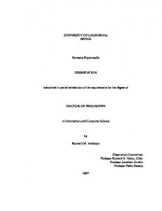
• RAID-3 - bit-level parity (dedicated parity disk) • N+1 disks, calculate parity (write all, read all) • Good sequential read/write bandwidth, poor random accesses • If N=8, only 13% overhead
• RAID-4/5 - block-level parity • Reads only data you need • Writes require read, calculate parity, write data&parity 17
CIS 501 (Martin/Roth): I/O
18
RAID-3: Bit-level parity
RAID 4/5 - Block-level Parity
• RAID-3 - bit-level parity
•
• dedicated parity disk • N+1 disks, calculate parity (write all, read all) • Good sequential read/write bandwidth, poor random accesses • If N=8, only 13% overhead
RAID-4/5 • •
•
Naïve approach 1. Read all disks 2. Calculate parity 3. Write data&parity
•
Better approach • • •
• CIS 501 (Martin/Roth): I/O
Reads only data you need Writes require read, calculate parity, write data&parity
© 2003 Elsevier Science
19
Read data&parity Calculate parity Write data&parity
Still worse for writes than RAID-3
CIS 501 (Martin/Roth): I/O
© 2003 Elsevier Science
20
RAID-4 vs RAID-5
Two Buses
• RAID-5 rotates the parity disk, avoid single-disk bottleneck
CPU
Mem
• Buses: connects system components • Insufficient bandwidth can bottleneck system • Performance factors • Physical length • Number and type of connected devices (taps)
Memory bridge
• Processor-memory bus
I/O
I/O
• Connects CPU and memory, no direct I/O interface + Short, few taps ! fast, high-bandwidth – System specific
I/O
• I/O bus • Connects I/O devices, no direct processor interface – Longer, more taps ! slower, lower-bandwidth + Industry standard
• Bridge connects these busses © 2003 Elsevier Science CIS 501 (Martin/Roth): I/O
21
Bus Design
• Wider + More bandwidth – More expensive and more susceptible to skew
• Goals • Performance: latency and bandwidth • Standardization: flexibility in dealing with many devices • Cost • Memory bus emphasize performance, then cost • I/O buses emphasize standardization, then performance
• Multiplexed: address and data on same lines + Cheaper – Less bandwidth
• Design issues
• Burst transfers
Width/multiplexing: shared or separate wires Clocking: bus clocked or not? Switching: how/when bus control is acquired and released Arbitration: deciding who gets the bus next
CIS 501 (Martin/Roth): I/O
22
Bus Width and Multiplexing data lines address lines control lines
• • • •
CIS 501 (Martin/Roth): I/O
• Multiple sequential data transactions for single address + Increase bandwidth at relatively little cost
23
CIS 501 (Martin/Roth): I/O
24
Bus Clocking
Bus Arbitration
•
• Bus master: component that can initiate a bus request
Synchronous: clocked + Fast – Must be short: to minimize clock skew
•
• Bus typically has several masters • Processor, but I/O devices can also be masters (Why? See in a bit)
Asynchronous: un-clocked + Longer: no clock skew, deals with devices of different speeds – Slower: requires “hand-shaking” protocol • For example, asynchronous read 1. Processor drives address onto bus, asserts Request line 2. Memory asserts Ack line, processor stops driving 3. Memory drives data on bus, asserts DataReady line 4. Processor asserts Ack line, memory stops driving
•
Source synchronous •
•
• Try to implement priority and fairness (no device “starves”) • Several different schemes (e.g., centralized, distributed)
• Daisy-chain: devices connect to bus in priority order • High-priority devices intercept/deny requests by low-priority ones ± Simple, but slow and can’t ensure fairness
• New trend: Point-to-point busses • Pro: No arbitration, no “master”, fast, simple, source synchronous • Con: need lots of wires or requires high per-wire bandwidth
A hybrid: send clock with data
Trend is away from asynchronous buses
CIS 501 (Martin/Roth): I/O
• Arbitration: choosing a master among multiple requests
25
Standard Bus Examples
CIS 501 (Martin/Roth): I/O
26
I/O Interfaces • Now that we know how I/O devices and buses work… • How does I/O actually happen?
PCI
SCSI
USB
Type
Backplane
I/O - disks
I/O
Width
32–64 bits
8–32 bits
1
Multiplexed?
Yes
Yes
Yes
Clocking
33 (66) MHz
5 (10) MHz
Asynchronous
Data rate
133 (266) MB/s
10 (20) MB/s
0.2, 1.5, 80 MB/s
Arbitration
Parallel
Self-selection
Daisy-chain
Maximum masters
1024
7–31
127
Maximum length
0.5 m
2.5 m
–
• How does CPU give commands to I/O devices? • How do I/O devices execute data transfers? • How does CPU know when I/O devices are done?
• USB (universal serial bus) • Popular for low-/moderate-bandwidth external peripherals + Packetized interface (like TCP) extremely flexible + Also supplies power to the peripheral CIS 501 (Martin/Roth): I/O
27
CIS 501 (Martin/Roth): I/O
28
I/O: Control + Data Transfer
OS Plays a Big Role
• I/O devices have two ports
• I/O interface is typically under OS control
• Control: commands and status reports • Tricky part (especially status reports) • Data: data • Labor intensive part • “Interesting” I/O devices do data transfers (to/from memory) • Display: video memory ! monitor • Disk: memory " disk • Network interface: memory " network card
• User applications access I/O devices indirectly (e.g., SYSCALL) • Why?
• Virtualization: same argument as for memory • Physical devices shared among multiple apps • Direct access could lead to conflicts
• Synchronization • Most have asynchronous interfaces, require unbounded waiting • OS handles asynchrony internally, presents synchronous interface
• Standardization • Devices of a certain type (disks) can/will have different interfaces • OS handles differences (via drivers), presents uniform interface CIS 501 (Martin/Roth): I/O
29
CIS 501 (Martin/Roth): I/O
Sending Commands to I/O Devices
Querying I/O Device Status
• Remember: only OS can do this • I/O instructions
• Sent command to I/O device… check • How to query I/O device status?
• OS only? Instructions are privileged • E.g., IA32
• So that you know if data you asked for is ready? • So that you know if device is ready to receive next command?
• Memory-mapped I/O • Portion of physical address space reserved for I/O • OS maps physical addresses to I/O device control registers • Stores/loads to these addresses are commands to I/O devices • Main memory ignores them, I/O devices recognize and respond • Address specifies both I/O device and command • Obviously, these address are not cached • OS only? I/O physical addresses only mapped in OS address space • E.g., almost every architecture other than IA32 CIS 501 (Martin/Roth): I/O
30
31
• Polling: Ready now? How about now? How about now? • Processor queries I/O device status register • Loops until it gets status it wants (ready for next command) • Or tries again a little later + Simple – Waste of processor’s time • Processor much faster than I/O device – Worse for higher bandwidth I/O devices (e.g., disks) CIS 501 (Martin/Roth): I/O
32
Polling Overhead
Interrupt-Driven I/O
• Parameters
• Interrupts: alternative to polling
• 500 MHz CPU • Polling event takes 400 cycles
• I/O device generates interrupt when status changes, data ready • OS handles interrupts just like exceptions (e.g., page faults) • Identity of interrupting I/O device recorded in ECR
• Overhead for polling a mouse 30 times per second?
• I/O interrupts are asynchronous • Not associated with any one insn • Don’t need to be handled immediately
• (30 poll/s) * [(400 c/poll)/(500M c/s)] = 0.002% + Not bad
• Overhead for polling a 4 MB/s disk with 16 B interface?
• I/O interrupts are prioritized • Synchronous interrupts (e.g., page faults) have highest priority • High-bandwidth I/O devices have higher priority than lowbandwidth ones
• (4M B/s)/(16 B/poll) * [(400 c/poll)/(500M c/s)] = 20% – Not good • This is the overhead of polling, not actual data transfer • Really bad if disk is not being used CIS 501 (Martin/Roth): I/O
33
CIS 501 (Martin/Roth): I/O
34
Interrupt Overhead
Direct Memory Access (DMA)
• Parameters
• Interrupts remove overhead of polling… • But still requires OS to transfer data one word at a time
• • • •
500 MHz CPU Interrupt handler takes 400 cycles Data transfer takes 100 cycles 4 MB/s, 16 B interface disk transfers data only 5% of time
• OK for low bandwidth I/O devices: mice, microphones, etc. • Bad for high bandwidth I/O devices: disks, monitors, etc.
• Direct Memory Access (DMA)
• Data transfer (x) time • 0.05 * (4M B/s)/(16 B/xfer)*[(100 c/xfer)/(500M c/s)] = 0.25%
• Overhead for polling? • (4M B/s)/(16 B/poll) * [(400 c/poll)/(500M c/s)] = 20%
• Block I/O memory transfers without processor control • Transfers entire blocks (e.g., pages, video frames) at a time • Can use bus “burst” transfer mode if available • Only interrupts processor when done (or if error occurs)
• Overhead for interrupts? + 0.05 * (4M B/s)/(16 B/poll) * [(400 c/poll)/(500M c/s)] = 1%
CIS 501 (Martin/Roth): I/O
35
CIS 501 (Martin/Roth): I/O
36
DMA Controllers
I/O Processors
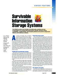
• To do DMA, I/O device attached to DMA controller
• A DMA controller is a very simple component
• Multiple devices can be connected to one controller • Controller itself seen as a memory mapped I/O device • Processor initializes start memory address, transfer size, etc. • DMA controller takes care of bus arbitration and transfer details • That’s why buses support arbitration and multiple masters CPU CPU Cache Cache
• May be as simple as a FSM with some local memory
• Some I/O requires complicated sequences of transfers • I/O processor: heavier DMA controller that executes instruction • Can be programmed to do complex transfers CPU Cache
CPU Cache
bridge
bridge
Memory bus
“System” (I/O) bus
DMA Memory
DMA
Memory bus
I/O ctrl
Memory
Memory kbd
Disk
CIS 501 (Martin/Roth): I/O
display
“System” (I/O) bus
kbd
NIC 37
DMA
DMA
I/O ctrl
Disk
display
NIC
Memory
CIS 501 (Martin/Roth): I/O
38
DMA Overhead
DMA and Address Translation
• Parameters
• Which addresses does processor specify to DMA controller?
• • • • •
500 MHz CPU Interrupt handler takes 400 cycles Data transfer takes 100 cycles 4 MB/s, 16 B interface disk transfers data 50% of time DMA setup takes 1600 cycles, transfer one 16KB page at a time
• Processor overhead for interrupt-driven I/O? • 0.5 * (4M B/s)/(16 B/i-xfer)*[(500 c/i-xfer)/(500M c/s)] = 12.5%
• Processor overhead with DMA? • Processor only gets involved once per page, not once per 16 B + 0.5 * (4M B/s)/(16K B/page) * [(2000 c/page)/(500M c/s)] = 0.05%
CIS 501 (Martin/Roth): I/O
39
• Virtual DMA + Can specify large cross-page transfers – DMA controller has to do address translation internally • DMA contains small translation lookaside buffer (TLB) • OS initializes buffer contents when it requests an I/O transfer
• Physical DMA + DMA controller is simple – Can only do short page-size transfers • OS breaks large transfers into page-size chunks
CIS 501 (Martin/Roth): I/O
40
DMA and Caching
Hardware Cache Coherence
• Caches are good
• D$ and L2 “snoop” bus traffic
CPU
• Reduce CPU’s observed instruction and data access latency + But also, reduce CPU’s use of memory… + …leaving majority of memory/bus bandwidth for DMA I/O
VA
VA
TLB I$
D$ TLB
PA
• But they also introduce a coherence problem for DMA • Input problem: all caches • DMA write into memory version of cached location • Cached version now stale • Output problem: write-back caches only • DMA read from memory version of “dirty” cached location • Output stale value
CIS 501 (Martin/Roth): I/O
L2 PA Bus
41
Observe transactions Check if written addresses are resident Self-invalidate those blocks Doesn’t require access to data part Does require access to tag part • May need 2nd copy of tags for this • That’s OK, tags smaller than data
• Bus addresses are physical DMA
Main Memory
• • • + –
Disk
• L2 is easy (physical index/tag) • D$ is harder (virtual index/physical tag) • Reverse translation? No • Remember: page size vs. D$ size
CIS 501 (Martin/Roth): I/O
42
Designing an I/O System for Bandwidth
Designing an I/O System for Bandwidth
• Approach
• First: determine I/O rates of components we can’t change
• Find bandwidths of individual components • Configure components you can change… • To match bandwidth of bottleneck component you can’t
• CPU: (300M insn/s) / (150K Insns/IO) = 2000 IO/s • I/O bus: (100M B/s) / (64K B/IO) = 1562 IO/s • Peak I/O rate determined by bus: 1562 IO/s
• Example • Parameters • 300 MIPS CPU, 100 MB/s I/O bus • 50K OS insns + 100K user insns per I/O operation • SCSI-2 controllers (20 MB/s): each accommodates up to 7 disks • 5 MB/s disks with tseek + trotation = 10 ms, 64 KB reads • Determine • What is the maximum sustainable I/O rate? • How many SCSI-2 controllers and disks does it require? • Assuming random reads
• Second: configure remaining components to match rate • Disk: 1 / [10 ms/IO + (64K B/IO) / (5M B/s)] = 43.9 IO/s • How many disks? • (1562 IO/s) / (43.9 IO/s) = 36 disks • How many controllers? • (43.9 IO/s) * (64K B/IO) = 2.74M B/s • (20M B/s) / (2.74M B/s) = 7.2 • (36 disks) / (7 disks/SCSI-2) = 6 SCSI-2 controllers
• Caveat: real I/O systems modeled with simulation CIS 501 (Martin/Roth): I/O
43
CIS 501 (Martin/Roth): I/O
44
Designing an I/O System for Latency
Summary
• Previous system designed for bandwidth • Some systems have latency requirements as well
• Role of the OS • Device characteristics
• E.g., database system may require maximum or average latency
• Latencies are actually harder to deal with than bandwidths • Unloaded system: few concurrent IO transactions • Latency is easy to calculate • Loaded system: many concurrent IO transactions • Contention can lead to queuing • Latencies can rise dramatically • Queuing theory can help if transactions obey fixed distribution • Otherwise simulation is needed
CIS 501 (Martin/Roth): I/O
45
• Data bandwidth • Disks • Structure and latency: seek, rotation, transfer, controller delays
• Bus characteristics • Processor-memory, I/O, and backplane buses • Width, multiplexing, clocking, switching, arbitration
• I/O control • I/O instructions vs. memory mapped I/O • Polling vs. interrupts • Processor controlled data transfer vs. DMA • Interaction of DMA with memory system CIS 501 (Martin/Roth): I/O
46