IBM Virtualization Engine TS7700 with R2.0. November ... First Edition (
November 2011) ..... 4.5 Implementing Outboard Policy Management for non-z/
OS hosts .
Front cover
IBM Virtualization Engine TS7700 with R 2.0 Integrate tape drives and IBM System p server into a storage hierarchy Manage your storage hierachy with advanced functions Take advantage of 5-way and 6-way grids
Karan Singh Søren Aakjær John Khazraee Tom Koudstaal Aderson J.C. Pacini Patrick Wolf
ibm.com/redbooks
International Technical Support Organization IBM Virtualization Engine TS7700 with R2.0 November 2011
SG24-7975-00
Note: Before using this information and the product it supports, read the information in “Notices” on page xiii.
First Edition (November 2011) This edition applies to Release 2.0 of IBM Virtualization Engine TS7700.
© Copyright International Business Machines Corporation 2011. All rights reserved. Note to U.S. Government Users Restricted Rights -- Use, duplication or disclosure restricted by GSA ADP Schedule Contract with IBM Corp.
Contents Notices . . . . . . . . . . . . . . . . . . . . . . . . . . . . . . . . . . . . . . . . . . . . . . . . . . . . . . . . . . . . . . . . xiii Trademarks . . . . . . . . . . . . . . . . . . . . . . . . . . . . . . . . . . . . . . . . . . . . . . . . . . . . . . . . . . . . . xiv Preface . . . . . . . . . . . . . . . . . . . . . . . . . . . . . . . . . . . . . . . . . . . . . . . . . . . . . . . . . . . . . . . . . xv Summary of contents . . . . . . . . . . . . . . . . . . . . . . . . . . . . . . . . . . . . . . . . . . . . . . . . . . . . . . . xv The team who wrote this book . . . . . . . . . . . . . . . . . . . . . . . . . . . . . . . . . . . . . . . . . . . . . . . xvii Now you can become a published author, too! . . . . . . . . . . . . . . . . . . . . . . . . . . . . . . . . . . xix Comments welcome. . . . . . . . . . . . . . . . . . . . . . . . . . . . . . . . . . . . . . . . . . . . . . . . . . . . . . . xix Stay connected to IBM Redbooks . . . . . . . . . . . . . . . . . . . . . . . . . . . . . . . . . . . . . . . . . . . . xix Part 1. Architecture and planning . . . . . . . . . . . . . . . . . . . . . . . . . . . . . . . . . . . . . . . . . . . . . . . . . . . . . . . . 1 Chapter 1. Introducing the IBM Virtualization Engine TS7700 . . . . . . . . . . . . . . . . . . . . 3 1.1 Overview . . . . . . . . . . . . . . . . . . . . . . . . . . . . . . . . . . . . . . . . . . . . . . . . . . . . . . . . . . . . . 4 1.2 Support capabilities . . . . . . . . . . . . . . . . . . . . . . . . . . . . . . . . . . . . . . . . . . . . . . . . . . . . . 4 1.3 Concepts of storage virtualization . . . . . . . . . . . . . . . . . . . . . . . . . . . . . . . . . . . . . . . . . . 9 1.4 Benefits of tape virtualization . . . . . . . . . . . . . . . . . . . . . . . . . . . . . . . . . . . . . . . . . . . . 13 1.5 Data storage values . . . . . . . . . . . . . . . . . . . . . . . . . . . . . . . . . . . . . . . . . . . . . . . . . . . 14 Chapter 2. Architecture, components, and functional characteristics . . . . . . . . . . . . 2.1 TS7700 Virtualization Engine architecture and terminology . . . . . . . . . . . . . . . . . . . . . 2.1.1 TS7700 Virtualization Engine specific terminology . . . . . . . . . . . . . . . . . . . . . . . . 2.1.2 Multi-cluster grid terms . . . . . . . . . . . . . . . . . . . . . . . . . . . . . . . . . . . . . . . . . . . . . 2.1.3 Tape virtualization general terms . . . . . . . . . . . . . . . . . . . . . . . . . . . . . . . . . . . . . 2.2 Architectural capabilities . . . . . . . . . . . . . . . . . . . . . . . . . . . . . . . . . . . . . . . . . . . . . . . . 2.2.1 Monolithic design of a VTS . . . . . . . . . . . . . . . . . . . . . . . . . . . . . . . . . . . . . . . . . . 2.2.2 Modular design of the TS7700 Virtualization Engine . . . . . . . . . . . . . . . . . . . . . . 2.2.3 Multi-cluster grid . . . . . . . . . . . . . . . . . . . . . . . . . . . . . . . . . . . . . . . . . . . . . . . . . . 2.2.4 TS7700 Virtualization Engine statistics for performance. . . . . . . . . . . . . . . . . . . . 2.2.5 Call Home support . . . . . . . . . . . . . . . . . . . . . . . . . . . . . . . . . . . . . . . . . . . . . . . . 2.3 TS7700 Virtualization Engine hardware components . . . . . . . . . . . . . . . . . . . . . . . . . . 2.3.1 Common components for the TS7720 Virtualization Engine and TS7740 Virtualization Engine models . . . . . . . . . . . . . . . . . . . . . . . . . . . . . . . . . . . . . . . . 2.3.2 TS7720 Virtualization Engine components . . . . . . . . . . . . . . . . . . . . . . . . . . . . . . 2.3.3 TS7740 Virtualization Engine components . . . . . . . . . . . . . . . . . . . . . . . . . . . . . . 2.3.4 TS3500 Tape Library . . . . . . . . . . . . . . . . . . . . . . . . . . . . . . . . . . . . . . . . . . . . . . 2.3.5 IBM TotalStorage 3592-J1A Tape Drive . . . . . . . . . . . . . . . . . . . . . . . . . . . . . . . . 2.3.6 IBM System Storage TS1120 Tape Drive . . . . . . . . . . . . . . . . . . . . . . . . . . . . . . . 2.3.7 IBM System Storage TS1130 Tape Drive . . . . . . . . . . . . . . . . . . . . . . . . . . . . . . . 2.4 TS7700 Virtualization Engine Concepts . . . . . . . . . . . . . . . . . . . . . . . . . . . . . . . . . . . . 2.4.1 Buffering data in the tape volume cache. . . . . . . . . . . . . . . . . . . . . . . . . . . . . . . . 2.4.2 Tape Volume Cache Management . . . . . . . . . . . . . . . . . . . . . . . . . . . . . . . . . . . . 2.4.3 Logical and stacked volume management . . . . . . . . . . . . . . . . . . . . . . . . . . . . . . 2.4.4 Copy Export . . . . . . . . . . . . . . . . . . . . . . . . . . . . . . . . . . . . . . . . . . . . . . . . . . . . . 2.4.5 Encryption . . . . . . . . . . . . . . . . . . . . . . . . . . . . . . . . . . . . . . . . . . . . . . . . . . . . . . . 2.4.6 Logical WORM (LWORM) support and characteristics. . . . . . . . . . . . . . . . . . . . . 2.4.7 Workflow management controls and alerts . . . . . . . . . . . . . . . . . . . . . . . . . . . . . . 2.4.8 Selective Device Access Control . . . . . . . . . . . . . . . . . . . . . . . . . . . . . . . . . . . . . 2.5 TS7700 Virtualization Engine multi-cluster grid . . . . . . . . . . . . . . . . . . . . . . . . . . . . . . Contents
15 17 17 27 30 35 35 36 36 37 38 39 40 43 48 52 56 57 57 59 59 60 68 76 79 82 82 84 85 iii
2.5.1 2.5.2 2.5.3 2.5.4 2.5.5 2.5.6 2.5.7
Data integrity by volume ownership . . . . . . . . . . . . . . . . . . . . . . . . . . . . . . . . . . . 85 Allocation Assistance . . . . . . . . . . . . . . . . . . . . . . . . . . . . . . . . . . . . . . . . . . . . . . 88 Copy policy management . . . . . . . . . . . . . . . . . . . . . . . . . . . . . . . . . . . . . . . . . . . 90 High availability and disaster recovery configurations . . . . . . . . . . . . . . . . . . . . 103 Selective Write Protect for Disaster Recovery testing. . . . . . . . . . . . . . . . . . . . . 111 Removal of a cluster from a grid and cluster clean-up . . . . . . . . . . . . . . . . . . . . 111 Joining of clusters at different code release levels . . . . . . . . . . . . . . . . . . . . . . . 115
Chapter 3. Preinstallation planning and sizing . . . . . . . . . . . . . . . . . . . . . . . . . . . . . . 3.1 Hardware configurations . . . . . . . . . . . . . . . . . . . . . . . . . . . . . . . . . . . . . . . . . . . . . . . 3.1.1 TS7740 Virtualization Engine configuration details. . . . . . . . . . . . . . . . . . . . . . . 3.1.2 TS7720 Virtualization Engine configuration details. . . . . . . . . . . . . . . . . . . . . . . 3.1.3 Cables . . . . . . . . . . . . . . . . . . . . . . . . . . . . . . . . . . . . . . . . . . . . . . . . . . . . . . . . . 3.1.4 Limitations . . . . . . . . . . . . . . . . . . . . . . . . . . . . . . . . . . . . . . . . . . . . . . . . . . . . . . 3.1.5 TS3500 Tape Library High Density frame for a TS7740 Virtualization Engine configuration . . . . . . . . . . . . . . . . . . . . . . . . . . . . . . . . . . . . . . . . . . . . . . . . . . . . 3.1.6 TS7700 Virtualization Engine upgrades and replacements . . . . . . . . . . . . . . . . 3.1.7 Expanded memory . . . . . . . . . . . . . . . . . . . . . . . . . . . . . . . . . . . . . . . . . . . . . . . 3.2 Hardware installation and infrastructure planning . . . . . . . . . . . . . . . . . . . . . . . . . . . . 3.2.1 System requirements . . . . . . . . . . . . . . . . . . . . . . . . . . . . . . . . . . . . . . . . . . . . . 3.2.2 TCP/IP configuration considerations. . . . . . . . . . . . . . . . . . . . . . . . . . . . . . . . . . 3.3 Remote installations and FICON switch support. . . . . . . . . . . . . . . . . . . . . . . . . . . . . 3.3.1 Factors that affect performance at a distance. . . . . . . . . . . . . . . . . . . . . . . . . . . 3.3.2 Host attachments . . . . . . . . . . . . . . . . . . . . . . . . . . . . . . . . . . . . . . . . . . . . . . . . 3.3.3 FICON Director support . . . . . . . . . . . . . . . . . . . . . . . . . . . . . . . . . . . . . . . . . . . 3.3.4 FICON channel extenders . . . . . . . . . . . . . . . . . . . . . . . . . . . . . . . . . . . . . . . . . 3.3.5 Implementing cascaded switches . . . . . . . . . . . . . . . . . . . . . . . . . . . . . . . . . . . . 3.4 High availability grid considerations . . . . . . . . . . . . . . . . . . . . . . . . . . . . . . . . . . . . . . 3.5 Planning for software implementation . . . . . . . . . . . . . . . . . . . . . . . . . . . . . . . . . . . . . 3.5.1 Host configuration definition . . . . . . . . . . . . . . . . . . . . . . . . . . . . . . . . . . . . . . . . 3.5.2 Software requirements . . . . . . . . . . . . . . . . . . . . . . . . . . . . . . . . . . . . . . . . . . . . 3.5.3 z/OS software environments . . . . . . . . . . . . . . . . . . . . . . . . . . . . . . . . . . . . . . . . 3.5.4 Sharing and partitioning considerations . . . . . . . . . . . . . . . . . . . . . . . . . . . . . . . 3.6 Planning for logical and physical volumes . . . . . . . . . . . . . . . . . . . . . . . . . . . . . . . . . 3.6.1 Logical volumes . . . . . . . . . . . . . . . . . . . . . . . . . . . . . . . . . . . . . . . . . . . . . . . . . 3.6.2 Logical WORM (LWORM). . . . . . . . . . . . . . . . . . . . . . . . . . . . . . . . . . . . . . . . . . 3.6.3 Physical volumes for TS7740 Virtualization Engine . . . . . . . . . . . . . . . . . . . . . . 3.6.4 Data compression . . . . . . . . . . . . . . . . . . . . . . . . . . . . . . . . . . . . . . . . . . . . . . . . 3.6.5 Secure Data Erase . . . . . . . . . . . . . . . . . . . . . . . . . . . . . . . . . . . . . . . . . . . . . . . 3.6.6 Copy Policy Override settings . . . . . . . . . . . . . . . . . . . . . . . . . . . . . . . . . . . . . . . 3.7 Planning for encryption in the TS7740 Virtualization Engine . . . . . . . . . . . . . . . . . . . 3.7.1 Pool encryption settings for TS7740 Virtualization Engine . . . . . . . . . . . . . . . . . 3.7.2 Encryption Key Manager. . . . . . . . . . . . . . . . . . . . . . . . . . . . . . . . . . . . . . . . . . . 3.7.3 Tivoli Key Lifecycle Manager . . . . . . . . . . . . . . . . . . . . . . . . . . . . . . . . . . . . . . . 3.7.4 IBM Security Key Lifecycle Manager . . . . . . . . . . . . . . . . . . . . . . . . . . . . . . . . . 3.7.5 Tape drives . . . . . . . . . . . . . . . . . . . . . . . . . . . . . . . . . . . . . . . . . . . . . . . . . . . . . 3.7.6 TS7740 Virtualization Engine . . . . . . . . . . . . . . . . . . . . . . . . . . . . . . . . . . . . . . . 3.7.7 Encryption Key Manager IP addresses. . . . . . . . . . . . . . . . . . . . . . . . . . . . . . . . 3.7.8 Encryption key management . . . . . . . . . . . . . . . . . . . . . . . . . . . . . . . . . . . . . . . 3.7.9 Installation . . . . . . . . . . . . . . . . . . . . . . . . . . . . . . . . . . . . . . . . . . . . . . . . . . . . . . 3.8 Tape analysis and sizing the TS7700 Virtualization Engine . . . . . . . . . . . . . . . . . . . . 3.8.1 IBM tape tools . . . . . . . . . . . . . . . . . . . . . . . . . . . . . . . . . . . . . . . . . . . . . . . . . . . 3.8.2 BatchMagic . . . . . . . . . . . . . . . . . . . . . . . . . . . . . . . . . . . . . . . . . . . . . . . . . . . . .
iv
IBM Virtualization Engine TS7700 with R2.0
117 118 119 125 130 131 132 133 137 138 138 140 148 148 149 151 152 152 153 155 155 156 156 157 158 158 161 161 165 165 167 169 170 172 172 172 173 173 173 175 176 176 176 180
3.8.3 Workload considerations. . . . . . . . . . . . . . . . . . . . . . . . . . . . . . . . . . . . . . . . . . . 3.9 Education and training . . . . . . . . . . . . . . . . . . . . . . . . . . . . . . . . . . . . . . . . . . . . . . . . 3.9.1 Adding a TS7740 Virtualization Engine to an existing TS3500 Tape Library . . . 3.9.2 Implementation services . . . . . . . . . . . . . . . . . . . . . . . . . . . . . . . . . . . . . . . . . . . 3.10 Planning considerations . . . . . . . . . . . . . . . . . . . . . . . . . . . . . . . . . . . . . . . . . . . . . .
180 183 183 184 185
Part 2. Implementation and migration. . . . . . . . . . . . . . . . . . . . . . . . . . . . . . . . . . . . . . . . . . . . . . . . . . . 187 Chapter 4. Hardware implementation . . . . . . . . . . . . . . . . . . . . . . . . . . . . . . . . . . . . . . 4.1 TS7700 Virtualization Engine implementation and installation considerations . . . . . . 4.1.1 Implementation tasks . . . . . . . . . . . . . . . . . . . . . . . . . . . . . . . . . . . . . . . . . . . . . 4.1.2 Installation tasks . . . . . . . . . . . . . . . . . . . . . . . . . . . . . . . . . . . . . . . . . . . . . . . . . 4.2 TS3500 Tape Library definitions (TS7740 Virtualization Engine) . . . . . . . . . . . . . . . . 4.2.1 Defining a logical library . . . . . . . . . . . . . . . . . . . . . . . . . . . . . . . . . . . . . . . . . . . 4.2.2 Adding drives to the logical library . . . . . . . . . . . . . . . . . . . . . . . . . . . . . . . . . . . 4.2.3 Defining control path drives . . . . . . . . . . . . . . . . . . . . . . . . . . . . . . . . . . . . . . . . 4.2.4 Defining the Encryption Method for the new logical library . . . . . . . . . . . . . . . . . 4.2.5 Defining Cartridge Assignment Policies . . . . . . . . . . . . . . . . . . . . . . . . . . . . . . . 4.2.6 Inserting TS7740 Virtualization Engine physical volumes. . . . . . . . . . . . . . . . . . 4.2.7 Assigning cartridges in TS3500 Tape Library to logical library partition . . . . . . . 4.3 Setting up the TS7700 Virtualization Engine. . . . . . . . . . . . . . . . . . . . . . . . . . . . . . . . 4.3.1 TS7700 Virtualization Engine definition with the management interface . . . . . . 4.3.2 Verifying the composite and distributed library sequence numbers . . . . . . . . . . 4.3.3 Defining VOLSER ranges for physical volumes . . . . . . . . . . . . . . . . . . . . . . . . . 4.3.4 Defining physical volume pools (TS7740 Virtualization Engine) . . . . . . . . . . . . . 4.3.5 Defining Fast Ready categories . . . . . . . . . . . . . . . . . . . . . . . . . . . . . . . . . . . . . 4.3.6 Defining the logical volume expiration time. . . . . . . . . . . . . . . . . . . . . . . . . . . . . 4.3.7 Events (formerly Operator Interventions) . . . . . . . . . . . . . . . . . . . . . . . . . . . . . . 4.3.8 Defining TS7700 constructs . . . . . . . . . . . . . . . . . . . . . . . . . . . . . . . . . . . . . . . . 4.3.9 TS7700 licensing . . . . . . . . . . . . . . . . . . . . . . . . . . . . . . . . . . . . . . . . . . . . . . . . 4.3.10 Defining Encryption Key Manager addresses . . . . . . . . . . . . . . . . . . . . . . . . . . 4.3.11 Defining SNMP . . . . . . . . . . . . . . . . . . . . . . . . . . . . . . . . . . . . . . . . . . . . . . . . . 4.3.12 Inserting logical volumes. . . . . . . . . . . . . . . . . . . . . . . . . . . . . . . . . . . . . . . . . . 4.4 Virtualization Engine multi-cluster grid definitions . . . . . . . . . . . . . . . . . . . . . . . . . . . . 4.4.1 Data access and availability characteristics . . . . . . . . . . . . . . . . . . . . . . . . . . . . 4.4.2 TS7700 grid configuration considerations for a two-cluster grid . . . . . . . . . . . . . 4.4.3 Defining grid copy mode control . . . . . . . . . . . . . . . . . . . . . . . . . . . . . . . . . . . . . 4.4.4 Defining scratch mount candidates . . . . . . . . . . . . . . . . . . . . . . . . . . . . . . . . . . . 4.4.5 Retain Copy Mode . . . . . . . . . . . . . . . . . . . . . . . . . . . . . . . . . . . . . . . . . . . . . . . 4.4.6 Defining cluster families . . . . . . . . . . . . . . . . . . . . . . . . . . . . . . . . . . . . . . . . . . . 4.4.7 TS7720 Cache thresholds and removal policies. . . . . . . . . . . . . . . . . . . . . . . . . 4.4.8 Backup and restore of construct definitions . . . . . . . . . . . . . . . . . . . . . . . . . . . . 4.4.9 Data management settings (TS7740 Virtualization Engine) . . . . . . . . . . . . . . . . 4.5 Implementing Outboard Policy Management for non-z/OS hosts . . . . . . . . . . . . . . . .
189 190 190 191 192 193 200 202 202 205 206 210 212 212 216 217 219 233 234 238 238 248 250 252 254 256 256 256 258 264 266 267 270 278 278 280
Chapter 5. Software implementation . . . . . . . . . . . . . . . . . . . . . . . . . . . . . . . . . . . . . . . 5.1 Host implementation considerations . . . . . . . . . . . . . . . . . . . . . . . . . . . . . . . . . . . . . . 5.1.1 Sharing the TS7700 Virtualization Engine by multiple hosts. . . . . . . . . . . . . . . . 5.1.2 Partitioning the TS7700 Virtualization Engine between multiple hosts . . . . . . . . 5.1.3 Logical path considerations . . . . . . . . . . . . . . . . . . . . . . . . . . . . . . . . . . . . . . . . 5.1.4 Library names, library IDs, and port IDs . . . . . . . . . . . . . . . . . . . . . . . . . . . . . . . 5.2 Hardware configuration definition . . . . . . . . . . . . . . . . . . . . . . . . . . . . . . . . . . . . . . . . 5.2.1 Defining devices through HCD for Cluster 0 . . . . . . . . . . . . . . . . . . . . . . . . . . . . 5.2.2 Activate the I/O configuration . . . . . . . . . . . . . . . . . . . . . . . . . . . . . . . . . . . . . . .
283 284 284 285 285 286 289 290 294
Contents
v
vi
5.2.3 HCD considerations for multi-cluster grid operation . . . . . . . . . . . . . . . . . . . . . . 5.2.4 More HCD and IOCP examples with a two-cluster grid . . . . . . . . . . . . . . . . . . . 5.2.5 Display and control your settings . . . . . . . . . . . . . . . . . . . . . . . . . . . . . . . . . . . . 5.2.6 Set values for the Missing Interrupt Handler . . . . . . . . . . . . . . . . . . . . . . . . . . . . 5.3 TS7700 Virtualization Engine software definitions for z/OS . . . . . . . . . . . . . . . . . . . . 5.3.1 z/OS and DFSMS/MVS system-managed tape . . . . . . . . . . . . . . . . . . . . . . . . . 5.3.2 Implementing Copy Export . . . . . . . . . . . . . . . . . . . . . . . . . . . . . . . . . . . . . . . . . 5.4 Implementing Selective Device Access Control . . . . . . . . . . . . . . . . . . . . . . . . . . . . . 5.4.1 Implementation of SDAC in z/OS . . . . . . . . . . . . . . . . . . . . . . . . . . . . . . . . . . . . 5.4.2 Implementation of SDAC from MI . . . . . . . . . . . . . . . . . . . . . . . . . . . . . . . . . . . . 5.5 TS7700 SETTING function . . . . . . . . . . . . . . . . . . . . . . . . . . . . . . . . . . . . . . . . . . . . . 5.6 Software implementation in z/VM and z/VSE . . . . . . . . . . . . . . . . . . . . . . . . . . . . . . . 5.6.1 General support information . . . . . . . . . . . . . . . . . . . . . . . . . . . . . . . . . . . . . . . . 5.6.2 z/VM native support using DFSMS/VM. . . . . . . . . . . . . . . . . . . . . . . . . . . . . . . . 5.6.3 Native z/VSE . . . . . . . . . . . . . . . . . . . . . . . . . . . . . . . . . . . . . . . . . . . . . . . . . . . . 5.6.4 VM/ESA and z/VM guest support . . . . . . . . . . . . . . . . . . . . . . . . . . . . . . . . . . . . 5.6.5 z/VSE as a z/VM guest using a VSE Guest Server (VGS) . . . . . . . . . . . . . . . . . 5.7 Software implementation in Transaction Processing Facility . . . . . . . . . . . . . . . . . . . 5.7.1 Usage considerations for TS7700 with TPF . . . . . . . . . . . . . . . . . . . . . . . . . . . . 5.7.2 Performance considerations for TS7700 multi-cluster grids with TPF . . . . . . . .
296 298 300 304 306 306 309 323 324 325 328 329 330 330 332 333 334 336 337 338
Chapter 6. Upgrade considerations . . . . . . . . . . . . . . . . . . . . . . . . . . . . . . . . . . . . . . . 6.1 TS7700 Virtualization Engine component upgrades . . . . . . . . . . . . . . . . . . . . . . . . . . 6.1.1 TS7700 Virtualization Engine concurrent system component upgrades. . . . . . . 6.1.2 TS7700 Virtualization Engine non-concurrent system component upgrades . . . 6.1.3 TS7720 Virtualization Engine Cache upgrade options . . . . . . . . . . . . . . . . . . . . 6.1.4 TS7740 Virtualization Engine Cache Upgrade options . . . . . . . . . . . . . . . . . . . . 6.2 Withdrawn hardware and features . . . . . . . . . . . . . . . . . . . . . . . . . . . . . . . . . . . . . . . 6.3 TS7700 Virtualization Engine upgrade to Release 2.0 . . . . . . . . . . . . . . . . . . . . . . . . 6.3.1 Planning for the upgrade. . . . . . . . . . . . . . . . . . . . . . . . . . . . . . . . . . . . . . . . . . . 6.4 Adding clusters to a grid . . . . . . . . . . . . . . . . . . . . . . . . . . . . . . . . . . . . . . . . . . . . . . . 6.4.1 TS7700 Virtualization Engine multi-cluster grid considerations . . . . . . . . . . . . . 6.4.2 Merge two TS7700 stand-alone clusters into a TS7700 two-cluster grid . . . . . . 6.4.3 Three-cluster grid configurations. . . . . . . . . . . . . . . . . . . . . . . . . . . . . . . . . . . . . 6.4.4 Four-cluster grid configurations. . . . . . . . . . . . . . . . . . . . . . . . . . . . . . . . . . . . . . 6.4.5 Five- and six-cluster configurations. . . . . . . . . . . . . . . . . . . . . . . . . . . . . . . . . . . 6.4.6 Hybrid TS7700 grid configurations . . . . . . . . . . . . . . . . . . . . . . . . . . . . . . . . . . .
341 342 342 343 344 349 352 356 356 357 357 359 362 372 379 381
Chapter 7. Migration aspects . . . . . . . . . . . . . . . . . . . . . . . . . . . . . . . . . . . . . . . . . . . . . 7.1 Migration to a TS7700 Virtualization Engine . . . . . . . . . . . . . . . . . . . . . . . . . . . . . . . . 7.2 Migration planning from VTS. . . . . . . . . . . . . . . . . . . . . . . . . . . . . . . . . . . . . . . . . . . . 7.2.1 VTS migration procedures and times . . . . . . . . . . . . . . . . . . . . . . . . . . . . . . . . . 7.2.2 IBM 3494 Tape Library attachment. . . . . . . . . . . . . . . . . . . . . . . . . . . . . . . . . . . 7.2.3 Licensed Internal Code levels . . . . . . . . . . . . . . . . . . . . . . . . . . . . . . . . . . . . . . . 7.2.4 General requirements and recommendations. . . . . . . . . . . . . . . . . . . . . . . . . . . 7.2.5 DFSMS definitions . . . . . . . . . . . . . . . . . . . . . . . . . . . . . . . . . . . . . . . . . . . . . . . 7.2.6 HCD definitions . . . . . . . . . . . . . . . . . . . . . . . . . . . . . . . . . . . . . . . . . . . . . . . . . . 7.3 Hardware migration process . . . . . . . . . . . . . . . . . . . . . . . . . . . . . . . . . . . . . . . . . . . . 7.3.1 Physical tape data format . . . . . . . . . . . . . . . . . . . . . . . . . . . . . . . . . . . . . . . . . . 7.3.2 Backing up VTS data . . . . . . . . . . . . . . . . . . . . . . . . . . . . . . . . . . . . . . . . . . . . . 7.3.3 Restoring VTS data. . . . . . . . . . . . . . . . . . . . . . . . . . . . . . . . . . . . . . . . . . . . . . . 7.4 Hardware migration scenarios for the TS7740 Virtualization Engine. . . . . . . . . . . . . . . . . . . . . . . . . . . . . . . . . . . . . . . . . . . . . . . . . .
385 386 387 387 388 389 389 389 390 390 390 391 392
IBM Virtualization Engine TS7700 with R2.0
393
7.4.1 Migrating a stand-alone VTS to a TS7740 stand-alone cluster. . . . . . . . . . . . . . 7.4.2 Merge multiple VTSs to a TS7740 stand-alone cluster. . . . . . . . . . . . . . . . . . . . 7.4.3 PTP VTS to TS7740 two-cluster grid . . . . . . . . . . . . . . . . . . . . . . . . . . . . . . . . . 7.5 New configuration upgrades introduced with R2.0 . . . . . . . . . . . . . . . . . . . . . . . . . . . 7.6 Upgrading drive models in a existing TS7740. . . . . . . . . . . . . . . . . . . . . . . . . . . . . . . 7.7 Moving data in and out of the TS7700 Virtualization Engine . . . . . . . . . . . . . . . . . . . 7.7.1 Phased method of moving data . . . . . . . . . . . . . . . . . . . . . . . . . . . . . . . . . . . . . 7.7.2 Quick method of moving data . . . . . . . . . . . . . . . . . . . . . . . . . . . . . . . . . . . . . . . 7.7.3 Products to simplify the task . . . . . . . . . . . . . . . . . . . . . . . . . . . . . . . . . . . . . . . . 7.7.4 Considerations for static VOLSERs . . . . . . . . . . . . . . . . . . . . . . . . . . . . . . . . . . 7.7.5 Combining methods to move data into the TS7700 Virtualization Engine . . . . . 7.7.6 Moving data out of the TS7700 Virtualization Engine . . . . . . . . . . . . . . . . . . . . . 7.8 Migration of DFSMShsm-managed data . . . . . . . . . . . . . . . . . . . . . . . . . . . . . . . . . . . 7.8.1 Volume and data set sizes . . . . . . . . . . . . . . . . . . . . . . . . . . . . . . . . . . . . . . . . . 7.8.2 TS7700 Virtualization Engine implementation considerations . . . . . . . . . . . . . . 7.8.3 DFSMShsm task-related considerations. . . . . . . . . . . . . . . . . . . . . . . . . . . . . . . 7.9 DFSMSrmm and other tape management systems . . . . . . . . . . . . . . . . . . . . . . . . . . 7.10 IBM Tivoli Storage Manager . . . . . . . . . . . . . . . . . . . . . . . . . . . . . . . . . . . . . . . . . . . 7.10.1 Guidance for TS7700 Virtualization Engine usage . . . . . . . . . . . . . . . . . . . . . . 7.10.2 Native drives . . . . . . . . . . . . . . . . . . . . . . . . . . . . . . . . . . . . . . . . . . . . . . . . . . . 7.10.3 IBM Tivoli Storage Manager parameter settings. . . . . . . . . . . . . . . . . . . . . . . . 7.11 DFSMSdss . . . . . . . . . . . . . . . . . . . . . . . . . . . . . . . . . . . . . . . . . . . . . . . . . . . . . . . . 7.11.1 Full volume dumps . . . . . . . . . . . . . . . . . . . . . . . . . . . . . . . . . . . . . . . . . . . . . . 7.11.2 Stand-Alone Services . . . . . . . . . . . . . . . . . . . . . . . . . . . . . . . . . . . . . . . . . . . . 7.12 Object access method. . . . . . . . . . . . . . . . . . . . . . . . . . . . . . . . . . . . . . . . . . . . . . . . 7.13 Database backups . . . . . . . . . . . . . . . . . . . . . . . . . . . . . . . . . . . . . . . . . . . . . . . . . . 7.13.1 DB2 data . . . . . . . . . . . . . . . . . . . . . . . . . . . . . . . . . . . . . . . . . . . . . . . . . . . . . . 7.13.2 CICS and IMS . . . . . . . . . . . . . . . . . . . . . . . . . . . . . . . . . . . . . . . . . . . . . . . . . . 7.13.3 Batch data . . . . . . . . . . . . . . . . . . . . . . . . . . . . . . . . . . . . . . . . . . . . . . . . . . . . .
393 399 406 412 416 419 420 421 424 425 426 426 429 430 432 434 437 438 439 440 440 441 441 441 443 444 444 446 447
Part 3. Operation . . . . . . . . . . . . . . . . . . . . . . . . . . . . . . . . . . . . . . . . . . . . . . . . . . . . . . . . . . . . . . . . . . . . 449 Chapter 8. Operation. . . . . . . . . . . . . . . . . . . . . . . . . . . . . . . . . . . . . . . . . . . . . . . . . . . . 8.1 User interfaces . . . . . . . . . . . . . . . . . . . . . . . . . . . . . . . . . . . . . . . . . . . . . . . . . . . . . . 8.2 TS3500 Tape Library Specialist . . . . . . . . . . . . . . . . . . . . . . . . . . . . . . . . . . . . . . . . . 8.3 Call Home and Electronic Customer Care . . . . . . . . . . . . . . . . . . . . . . . . . . . . . . . . . 8.3.1 Electronic Customer Care . . . . . . . . . . . . . . . . . . . . . . . . . . . . . . . . . . . . . . . . . . 8.4 TS7700 Virtualization Engine Management Interface . . . . . . . . . . . . . . . . . . . . . . . . . 8.4.1 Connecting to the MI . . . . . . . . . . . . . . . . . . . . . . . . . . . . . . . . . . . . . . . . . . . . . . 8.4.2 Using the management interface . . . . . . . . . . . . . . . . . . . . . . . . . . . . . . . . . . . . 8.4.3 Health & Monitoring . . . . . . . . . . . . . . . . . . . . . . . . . . . . . . . . . . . . . . . . . . . . . . 8.4.4 Performance and Statistics windows . . . . . . . . . . . . . . . . . . . . . . . . . . . . . . . . . 8.4.5 Logical volumes . . . . . . . . . . . . . . . . . . . . . . . . . . . . . . . . . . . . . . . . . . . . . . . . . 8.4.6 Physical volumes . . . . . . . . . . . . . . . . . . . . . . . . . . . . . . . . . . . . . . . . . . . . . . . . 8.4.7 Constructs . . . . . . . . . . . . . . . . . . . . . . . . . . . . . . . . . . . . . . . . . . . . . . . . . . . . . . 8.4.8 Configuration. . . . . . . . . . . . . . . . . . . . . . . . . . . . . . . . . . . . . . . . . . . . . . . . . . . . 8.4.9 User management . . . . . . . . . . . . . . . . . . . . . . . . . . . . . . . . . . . . . . . . . . . . . . . 8.4.10 Service and troubleshooting . . . . . . . . . . . . . . . . . . . . . . . . . . . . . . . . . . . . . . . 8.4.11 Drive cleaning . . . . . . . . . . . . . . . . . . . . . . . . . . . . . . . . . . . . . . . . . . . . . . . . . . 8.5 System-managed tape . . . . . . . . . . . . . . . . . . . . . . . . . . . . . . . . . . . . . . . . . . . . . . . . 8.5.1 DFSMS operator commands. . . . . . . . . . . . . . . . . . . . . . . . . . . . . . . . . . . . . . . . 8.5.2 Library LMPOLICY command . . . . . . . . . . . . . . . . . . . . . . . . . . . . . . . . . . . . . . . 8.5.3 Host Console Request function . . . . . . . . . . . . . . . . . . . . . . . . . . . . . . . . . . . . .
Contents
451 452 453 454 454 457 457 461 462 479 480 502 521 529 546 566 583 585 585 588 589
vii
viii
8.5.4 MVS System commands. . . . . . . . . . . . . . . . . . . . . . . . . . . . . . . . . . . . . . . . . . . 8.6 Basic operations . . . . . . . . . . . . . . . . . . . . . . . . . . . . . . . . . . . . . . . . . . . . . . . . . . . . . 8.6.1 Clock and time setting. . . . . . . . . . . . . . . . . . . . . . . . . . . . . . . . . . . . . . . . . . . . . 8.6.2 Library online/offline to host . . . . . . . . . . . . . . . . . . . . . . . . . . . . . . . . . . . . . . . . 8.6.3 Library in Pause mode . . . . . . . . . . . . . . . . . . . . . . . . . . . . . . . . . . . . . . . . . . . . 8.6.4 Preparing for service . . . . . . . . . . . . . . . . . . . . . . . . . . . . . . . . . . . . . . . . . . . . . . 8.6.5 TS3500 Tape Library inventory. . . . . . . . . . . . . . . . . . . . . . . . . . . . . . . . . . . . . . 8.6.6 Inventory upload . . . . . . . . . . . . . . . . . . . . . . . . . . . . . . . . . . . . . . . . . . . . . . . . . 8.7 Tape cartridge management . . . . . . . . . . . . . . . . . . . . . . . . . . . . . . . . . . . . . . . . . . . . 8.7.1 3592 tape cartridges and labels . . . . . . . . . . . . . . . . . . . . . . . . . . . . . . . . . . . . . 8.7.2 Manual insertion of stacked cartridges . . . . . . . . . . . . . . . . . . . . . . . . . . . . . . . . 8.7.3 Exception conditions . . . . . . . . . . . . . . . . . . . . . . . . . . . . . . . . . . . . . . . . . . . . . . 8.8 Managing logical volumes . . . . . . . . . . . . . . . . . . . . . . . . . . . . . . . . . . . . . . . . . . . . . . 8.8.1 Scratch volume recovery for logical volumes . . . . . . . . . . . . . . . . . . . . . . . . . . . 8.8.2 Ejecting logical volumes . . . . . . . . . . . . . . . . . . . . . . . . . . . . . . . . . . . . . . . . . . . 8.9 Messages and displays . . . . . . . . . . . . . . . . . . . . . . . . . . . . . . . . . . . . . . . . . . . . . . . . 8.9.1 Console name message routing . . . . . . . . . . . . . . . . . . . . . . . . . . . . . . . . . . . . . 8.9.2 Alert setting messages . . . . . . . . . . . . . . . . . . . . . . . . . . . . . . . . . . . . . . . . . . . . 8.9.3 Grid messages . . . . . . . . . . . . . . . . . . . . . . . . . . . . . . . . . . . . . . . . . . . . . . . . . . 8.9.4 Display grid status. . . . . . . . . . . . . . . . . . . . . . . . . . . . . . . . . . . . . . . . . . . . . . . . 8.9.5 Warning link status degraded messages . . . . . . . . . . . . . . . . . . . . . . . . . . . . . . 8.9.6 Warning VTS operation degraded messages . . . . . . . . . . . . . . . . . . . . . . . . . . . 8.9.7 Warning cache use capacity (TS7720 Virtualization Engine) . . . . . . . . . . . . . . . 8.10 Recovery scenarios. . . . . . . . . . . . . . . . . . . . . . . . . . . . . . . . . . . . . . . . . . . . . . . . . . 8.10.1 Hardware conditions . . . . . . . . . . . . . . . . . . . . . . . . . . . . . . . . . . . . . . . . . . . . . 8.10.2 TS7700 Virtualization Engine software failure . . . . . . . . . . . . . . . . . . . . . . . . . 8.11 TS7720 Virtualization Engine operation considerations . . . . . . . . . . . . . . . . . . . . . . 8.11.1 Management interface for TS7720 . . . . . . . . . . . . . . . . . . . . . . . . . . . . . . . . . .
612 614 614 614 615 615 616 617 617 617 619 620 622 622 622 624 624 624 624 626 627 628 628 628 628 632 632 633
Chapter 9. Performance and Monitoring . . . . . . . . . . . . . . . . . . . . . . . . . . . . . . . . . . . . 9.1 TS7700 Virtualization Engine performance characteristics. . . . . . . . . . . . . . . . . . . . . 9.1.1 Performance overview . . . . . . . . . . . . . . . . . . . . . . . . . . . . . . . . . . . . . . . . . . . . 9.2 TS7700 components and tasks distribution . . . . . . . . . . . . . . . . . . . . . . . . . . . . . . . . 9.2.1 Tasks performed by CPU (processor cycles) . . . . . . . . . . . . . . . . . . . . . . . . . . . 9.2.2 Tasks performed by the TS7700 tape volume cache . . . . . . . . . . . . . . . . . . . . . 9.2.3 Tasks performed by the grid . . . . . . . . . . . . . . . . . . . . . . . . . . . . . . . . . . . . . . . . 9.2.4 Tasks performed by the TS7740 Tape Drives . . . . . . . . . . . . . . . . . . . . . . . . . . 9.3 Throttling, tasks, and knobs . . . . . . . . . . . . . . . . . . . . . . . . . . . . . . . . . . . . . . . . . . . . 9.3.1 Throttling in the TS7700 . . . . . . . . . . . . . . . . . . . . . . . . . . . . . . . . . . . . . . . . . . . 9.3.2 Host Write Throttle . . . . . . . . . . . . . . . . . . . . . . . . . . . . . . . . . . . . . . . . . . . . . . . 9.3.3 Copy Throttle . . . . . . . . . . . . . . . . . . . . . . . . . . . . . . . . . . . . . . . . . . . . . . . . . . . 9.3.4 Deferred Copy Throttle . . . . . . . . . . . . . . . . . . . . . . . . . . . . . . . . . . . . . . . . . . . . 9.3.5 Managing tasks within TS7700 . . . . . . . . . . . . . . . . . . . . . . . . . . . . . . . . . . . . . . 9.3.6 TS7740 tape drives and overall cluster performance . . . . . . . . . . . . . . . . . . . . . 9.4 Virtual Device Allocation in z/OS with JES2 . . . . . . . . . . . . . . . . . . . . . . . . . . . . . . . . 9.4.1 EQUAL Allocation . . . . . . . . . . . . . . . . . . . . . . . . . . . . . . . . . . . . . . . . . . . . . . . . 9.4.2 BYDEVICES Allocation . . . . . . . . . . . . . . . . . . . . . . . . . . . . . . . . . . . . . . . . . . . . 9.4.3 Allocation and Copy Consistency Point setting. . . . . . . . . . . . . . . . . . . . . . . . . . 9.4.4 Allocation and Device Allocation Assistance. . . . . . . . . . . . . . . . . . . . . . . . . . . . 9.4.5 Allocation and Scratch Allocation Assistance . . . . . . . . . . . . . . . . . . . . . . . . . . . 9.5 Data movement through tape volume cache . . . . . . . . . . . . . . . . . . . . . . . . . . . . . . . 9.5.1 Cache Data Flow in a TS7700 two-cluster grid. . . . . . . . . . . . . . . . . . . . . . . . . . 9.5.2 Cache data flow in a TS7700 three-cluster grid . . . . . . . . . . . . . . . . . . . . . . . . .
635 637 638 640 641 642 642 643 643 644 644 645 647 648 651 653 655 657 659 661 664 667 669 670
IBM Virtualization Engine TS7700 with R2.0
9.5.3 TS7700 Four-cluster grid considerations . . . . . . . . . . . . . . . . . . . . . . . . . . . . . . 9.5.4 TS7700 hybrid grid considerations . . . . . . . . . . . . . . . . . . . . . . . . . . . . . . . . . . . 9.5.5 Cluster families and cooperative replication . . . . . . . . . . . . . . . . . . . . . . . . . . . . 9.5.6 Retain Copy Mode . . . . . . . . . . . . . . . . . . . . . . . . . . . . . . . . . . . . . . . . . . . . . . . 9.6 Monitoring TS7700 Virtualization Engine performance . . . . . . . . . . . . . . . . . . . . . . . . 9.6.1 Using the TS3500 Tape Library Specialist for monitoring. . . . . . . . . . . . . . . . . . 9.6.2 Using the TS7700 Virtualization Engine management interface for monitoring . 9.7 Tuning the TS7700 . . . . . . . . . . . . . . . . . . . . . . . . . . . . . . . . . . . . . . . . . . . . . . . . . . . 9.7.1 Plotting cache throughput from VEHSTATS . . . . . . . . . . . . . . . . . . . . . . . . . . . . 9.7.2 Interpreting cache throughput . . . . . . . . . . . . . . . . . . . . . . . . . . . . . . . . . . . . . . . 9.7.3 Adjusting the TS7700 . . . . . . . . . . . . . . . . . . . . . . . . . . . . . . . . . . . . . . . . . . . . . 9.8 TS7700 Virtualization Engine statistical data . . . . . . . . . . . . . . . . . . . . . . . . . . . . . . . 9.8.1 Types of statistical records . . . . . . . . . . . . . . . . . . . . . . . . . . . . . . . . . . . . . . . . . 9.8.2 Collecting and analyzing TS7700 Virtualization Engine statistical records . . . . . 9.9 Bulk Volume Information Retrieval . . . . . . . . . . . . . . . . . . . . . . . . . . . . . . . . . . . . . . . 9.9.1 Overview of the BVIR function . . . . . . . . . . . . . . . . . . . . . . . . . . . . . . . . . . . . . . 9.9.2 Prerequisites . . . . . . . . . . . . . . . . . . . . . . . . . . . . . . . . . . . . . . . . . . . . . . . . . . . . 9.9.3 Request data format . . . . . . . . . . . . . . . . . . . . . . . . . . . . . . . . . . . . . . . . . . . . . . 9.9.4 Response data format. . . . . . . . . . . . . . . . . . . . . . . . . . . . . . . . . . . . . . . . . . . . . 9.9.5 Interpreting the BVIR response data. . . . . . . . . . . . . . . . . . . . . . . . . . . . . . . . . . 9.10 IBM Tape Tools . . . . . . . . . . . . . . . . . . . . . . . . . . . . . . . . . . . . . . . . . . . . . . . . . . . . . 9.10.1 Introduction to IBM Tape Tools . . . . . . . . . . . . . . . . . . . . . . . . . . . . . . . . . . . . . 9.10.2 Tools download and installation . . . . . . . . . . . . . . . . . . . . . . . . . . . . . . . . . . . . 9.10.3 IBM Tape Tools for TS7700 monitoring . . . . . . . . . . . . . . . . . . . . . . . . . . . . . . 9.11 Using VEHSTATS and VEHGRXCL for monitoring and reporting . . . . . . . . . . . . . . 9.11.1 VEHSTATS tool overview . . . . . . . . . . . . . . . . . . . . . . . . . . . . . . . . . . . . . . . . . 9.11.2 Running the VEHSTATS jobs . . . . . . . . . . . . . . . . . . . . . . . . . . . . . . . . . . . . . . 9.11.3 VEHSTATS reports . . . . . . . . . . . . . . . . . . . . . . . . . . . . . . . . . . . . . . . . . . . . . . 9.11.4 VEHGRXCL tool overview . . . . . . . . . . . . . . . . . . . . . . . . . . . . . . . . . . . . . . . . 9.12 z/OS commands for monitoring. . . . . . . . . . . . . . . . . . . . . . . . . . . . . . . . . . . . . . . . . 9.12.1 Display SMS command. . . . . . . . . . . . . . . . . . . . . . . . . . . . . . . . . . . . . . . . . . . 9.12.2 Library command . . . . . . . . . . . . . . . . . . . . . . . . . . . . . . . . . . . . . . . . . . . . . . . 9.13 What to look for and where . . . . . . . . . . . . . . . . . . . . . . . . . . . . . . . . . . . . . . . . . . . .
673 675 675 677 680 681 683 695 695 696 698 706 706 710 711 711 714 714 717 718 727 727 729 731 732 733 733 735 739 743 743 745 746
Chapter 10. Failover and disaster recovery scenarios . . . . . . . . . . . . . . . . . . . . . . . . 10.1 TS7700 Virtualization Engine grid failover principles . . . . . . . . . . . . . . . . . . . . . . . . 10.2 Failover scenarios . . . . . . . . . . . . . . . . . . . . . . . . . . . . . . . . . . . . . . . . . . . . . . . . . . . 10.2.1 Test configuration . . . . . . . . . . . . . . . . . . . . . . . . . . . . . . . . . . . . . . . . . . . . . . . 10.2.2 Failover scenario 1 . . . . . . . . . . . . . . . . . . . . . . . . . . . . . . . . . . . . . . . . . . . . . . 10.2.3 Failover scenario 2 . . . . . . . . . . . . . . . . . . . . . . . . . . . . . . . . . . . . . . . . . . . . . . 10.2.4 Failover scenario 3 . . . . . . . . . . . . . . . . . . . . . . . . . . . . . . . . . . . . . . . . . . . . . . 10.2.5 Failover scenario 4 . . . . . . . . . . . . . . . . . . . . . . . . . . . . . . . . . . . . . . . . . . . . . . 10.2.6 Failover scenario 5 . . . . . . . . . . . . . . . . . . . . . . . . . . . . . . . . . . . . . . . . . . . . . . 10.2.7 Failover scenario 6 . . . . . . . . . . . . . . . . . . . . . . . . . . . . . . . . . . . . . . . . . . . . . . 10.2.8 Failover scenario 7 . . . . . . . . . . . . . . . . . . . . . . . . . . . . . . . . . . . . . . . . . . . . . . 10.2.9 Failover scenario 8 . . . . . . . . . . . . . . . . . . . . . . . . . . . . . . . . . . . . . . . . . . . . . . 10.3 Planning for disaster recovery. . . . . . . . . . . . . . . . . . . . . . . . . . . . . . . . . . . . . . . . . . 10.3.1 Grid configuration . . . . . . . . . . . . . . . . . . . . . . . . . . . . . . . . . . . . . . . . . . . . . . . 10.3.2 Planning guidelines . . . . . . . . . . . . . . . . . . . . . . . . . . . . . . . . . . . . . . . . . . . . . . 10.3.3 Disaster recovery considerations with TS7740 and TS7720 . . . . . . . . . . . . . . 10.4 Disaster recovery using Copy Export . . . . . . . . . . . . . . . . . . . . . . . . . . . . . . . . . . . . 10.4.1 Planning and considerations for testing Copy Export Recovery . . . . . . . . . . . . 10.4.2 Grid considerations for Copy Export . . . . . . . . . . . . . . . . . . . . . . . . . . . . . . . . .
749 750 753 754 755 756 757 758 759 760 761 762 763 763 764 765 766 766 768
Contents
ix
10.4.3 Performing Copy Export Recovery . . . . . . . . . . . . . . . . . . . . . . . . . . . . . . . . . . 10.4.4 Restoring the host and library environments. . . . . . . . . . . . . . . . . . . . . . . . . . . 10.5 Geographically Dispersed Parallel Sysplex . . . . . . . . . . . . . . . . . . . . . . . . . . . . . . . 10.5.1 GDPS functions . . . . . . . . . . . . . . . . . . . . . . . . . . . . . . . . . . . . . . . . . . . . . . . . 10.5.2 GDPS considerations in a TS7740 grid configuration. . . . . . . . . . . . . . . . . . . . 10.6 Disaster recovery testing considerations . . . . . . . . . . . . . . . . . . . . . . . . . . . . . . . . . 10.6.1 The test environment represents a point in time . . . . . . . . . . . . . . . . . . . . . . . . 10.6.2 Breaking the interconnects between the TS7700 Virtualization Engines . . . . . 10.6.3 Writing data during the test . . . . . . . . . . . . . . . . . . . . . . . . . . . . . . . . . . . . . . . . 10.6.4 Protecting production volumes with Selective Write Protect . . . . . . . . . . . . . . . 10.6.5 Protecting production volumes with DFSMSrmm . . . . . . . . . . . . . . . . . . . . . . . 10.6.6 Control of copies . . . . . . . . . . . . . . . . . . . . . . . . . . . . . . . . . . . . . . . . . . . . . . . . 10.6.7 Return-to-scratch processing and test use of older volumes . . . . . . . . . . . . . . 10.6.8 Copies flushed or kept as LRU . . . . . . . . . . . . . . . . . . . . . . . . . . . . . . . . . . . . . 10.6.9 Ownership takeover . . . . . . . . . . . . . . . . . . . . . . . . . . . . . . . . . . . . . . . . . . . . . 10.7 Disaster recovery testing detailed procedures . . . . . . . . . . . . . . . . . . . . . . . . . . . . . 10.7.1 TS7700 two-cluster grid using Selective Write Protect . . . . . . . . . . . . . . . . . . . 10.7.2 TS7700 two-cluster grid not using Selective Write Protect . . . . . . . . . . . . . . . . 10.7.3 TS7700 two-cluster grid not using Selective Write Protect . . . . . . . . . . . . . . . . 10.7.4 TS7700 three-cluster grid not using Selective Write Protect. . . . . . . . . . . . . . . 10.8 A real disaster . . . . . . . . . . . . . . . . . . . . . . . . . . . . . . . . . . . . . . . . . . . . . . . . . . . . . .
769 775 776 776 777 779 779 779 780 781 782 784 785 786 786 787 788 791 794 797 801
Part 4. Appendixes . . . . . . . . . . . . . . . . . . . . . . . . . . . . . . . . . . . . . . . . . . . . . . . . . . . . . . . . . . . . . . . . . . 803 Appendix A. Feature codes . . . . . . . . . . . . . . . . . . . . . . . . . . . . . . . . . . . . . . . . . . . . . . Feature code (FC) lists. . . . . . . . . . . . . . . . . . . . . . . . . . . . . . . . . . . . . . . . . . . . . . . . . . . . Server features for 3494 B10 and B20 VTS, 3957-V06, 3957-V07, 3957-VEA, and 3957-VEB . . . . . . . . . . . . . . . . . . . . . . . . . . . . . . . . . . . . . . . . . . . . . . . . . . . . . . . Cache Controller features for 3956-CC6, 3956-CC7, and 3956-CS8 . . . . . . . . . . . . . . TS7700 Cache Drawer features 3956-CX6, 3956-CX7, and 3956-XS7 . . . . . . . . . . . . TS7700 Virtualization Engine feature code descriptions . . . . . . . . . . . . . . . . . . . . . . . . . .
805 806 807 809 810 810
Appendix B. IBM Virtualization Engine TS7700 implementation steps . . . . . . . . . . . 823
x
Appendix C. TS3500 and TS7700 checklists . . . . . . . . . . . . . . . . . . . . . . . . . . . . . . . . TS7700 Virtualization Engine installation worksheets . . . . . . . . . . . . . . . . . . . . . . . . . . . . Grid cluster descriptions . . . . . . . . . . . . . . . . . . . . . . . . . . . . . . . . . . . . . . . . . . . . . . . . TS3500 Tape Library configuration information . . . . . . . . . . . . . . . . . . . . . . . . . . . . . . . . . TS3500 Tape Library drive information worksheet . . . . . . . . . . . . . . . . . . . . . . . . . . . . . . Media volume serial range . . . . . . . . . . . . . . . . . . . . . . . . . . . . . . . . . . . . . . . . . . . . . . . . . TS7700 Virtualization Engine configuration information . . . . . . . . . . . . . . . . . . . . . . . . . . Grid local address . . . . . . . . . . . . . . . . . . . . . . . . . . . . . . . . . . . . . . . . . . . . . . . . . . . . . . . TSSC grid configuration information . . . . . . . . . . . . . . . . . . . . . . . . . . . . . . . . . . . . . . . . .
829 830 830 831 832 835 837 840 844
Appendix D. JES3 examples and information . . . . . . . . . . . . . . . . . . . . . . . . . . . . . . . JES3 support for system-managed tape . . . . . . . . . . . . . . . . . . . . . . . . . . . . . . . . . . . . . . Example with two separate Tape Libraries . . . . . . . . . . . . . . . . . . . . . . . . . . . . . . . . . . . . LDG definitions necessary for the first example . . . . . . . . . . . . . . . . . . . . . . . . . . . . . . Device statements needed for this configuration . . . . . . . . . . . . . . . . . . . . . . . . . . . . . SETNAME statements needed for this configuration . . . . . . . . . . . . . . . . . . . . . . . . . . HWSNAME statement needed for this configuration . . . . . . . . . . . . . . . . . . . . . . . . . . Example with three Tape Libraries. . . . . . . . . . . . . . . . . . . . . . . . . . . . . . . . . . . . . . . . . . . LDG definitions needed for the second configuration example. . . . . . . . . . . . . . . . . . . Device statement needed . . . . . . . . . . . . . . . . . . . . . . . . . . . . . . . . . . . . . . . . . . . . . . .
847 848 852 852 853 853 854 854 855 856
IBM Virtualization Engine TS7700 with R2.0
SETNAME statements needed . . . . . . . . . . . . . . . . . . . . . . . . . . . . . . . . . . . . . . . . . . . High watermark setup name statements. . . . . . . . . . . . . . . . . . . . . . . . . . . . . . . . . . . . Processing changes . . . . . . . . . . . . . . . . . . . . . . . . . . . . . . . . . . . . . . . . . . . . . . . . . . . . . . JES3/DFSMS processing . . . . . . . . . . . . . . . . . . . . . . . . . . . . . . . . . . . . . . . . . . . . . . . Selecting UNITNAMEs . . . . . . . . . . . . . . . . . . . . . . . . . . . . . . . . . . . . . . . . . . . . . . . . . New or modified data sets . . . . . . . . . . . . . . . . . . . . . . . . . . . . . . . . . . . . . . . . . . . . . . Old data sets . . . . . . . . . . . . . . . . . . . . . . . . . . . . . . . . . . . . . . . . . . . . . . . . . . . . . . . . . DFSMS catalog processing. . . . . . . . . . . . . . . . . . . . . . . . . . . . . . . . . . . . . . . . . . . . . . DFSMS VOLREF processing . . . . . . . . . . . . . . . . . . . . . . . . . . . . . . . . . . . . . . . . . . . . Fetch messages . . . . . . . . . . . . . . . . . . . . . . . . . . . . . . . . . . . . . . . . . . . . . . . . . . . . . . JES3 allocation and mounting . . . . . . . . . . . . . . . . . . . . . . . . . . . . . . . . . . . . . . . . . . . Multi-cluster grid considerations . . . . . . . . . . . . . . . . . . . . . . . . . . . . . . . . . . . . . . . . . .
857 857 857 859 859 859 859 859 860 860 860 861
Appendix E. Case study for logical partitioning of a two-cluster grid . . . . . . . . . . . . Overview of partitioning . . . . . . . . . . . . . . . . . . . . . . . . . . . . . . . . . . . . . . . . . . . . . . . . . . . Definitions and settings in z/OS . . . . . . . . . . . . . . . . . . . . . . . . . . . . . . . . . . . . . . . . . . . . . Definitions in HCD. . . . . . . . . . . . . . . . . . . . . . . . . . . . . . . . . . . . . . . . . . . . . . . . . . . . . PARMLIB definitions . . . . . . . . . . . . . . . . . . . . . . . . . . . . . . . . . . . . . . . . . . . . . . . . . . . DFSMSrmm definitions . . . . . . . . . . . . . . . . . . . . . . . . . . . . . . . . . . . . . . . . . . . . . . . . . JES2 definitions . . . . . . . . . . . . . . . . . . . . . . . . . . . . . . . . . . . . . . . . . . . . . . . . . . . . . . SMS constructs and definitions. . . . . . . . . . . . . . . . . . . . . . . . . . . . . . . . . . . . . . . . . . . RACF definitions . . . . . . . . . . . . . . . . . . . . . . . . . . . . . . . . . . . . . . . . . . . . . . . . . . . . . . Automation activities . . . . . . . . . . . . . . . . . . . . . . . . . . . . . . . . . . . . . . . . . . . . . . . . . . . Definitions on the TS7700 Management Interface . . . . . . . . . . . . . . . . . . . . . . . . . . . . . . . Physical volume pools . . . . . . . . . . . . . . . . . . . . . . . . . . . . . . . . . . . . . . . . . . . . . . . . . Fast ready categories . . . . . . . . . . . . . . . . . . . . . . . . . . . . . . . . . . . . . . . . . . . . . . . . . . Define constructs . . . . . . . . . . . . . . . . . . . . . . . . . . . . . . . . . . . . . . . . . . . . . . . . . . . . . Library Port Access Groups . . . . . . . . . . . . . . . . . . . . . . . . . . . . . . . . . . . . . . . . . . . . . Logical Volume Ranges or insert volumes connected to defined ranges . . . . . . . . . . . User Management on MI . . . . . . . . . . . . . . . . . . . . . . . . . . . . . . . . . . . . . . . . . . . . . . . Verification of changes . . . . . . . . . . . . . . . . . . . . . . . . . . . . . . . . . . . . . . . . . . . . . . . . . . . .
863 864 865 866 867 869 870 870 871 871 872 872 873 874 876 877 878 878
Appendix F. Sample JCL . . . . . . . . . . . . . . . . . . . . . . . . . . . . . . . . . . . . . . . . . . . . . . . . BVIR jobs to obtain historical data . . . . . . . . . . . . . . . . . . . . . . . . . . . . . . . . . . . . . . . . . . . BVIRHSTS . . . . . . . . . . . . . . . . . . . . . . . . . . . . . . . . . . . . . . . . . . . . . . . . . . . . . . . . . . BVIRHSTU . . . . . . . . . . . . . . . . . . . . . . . . . . . . . . . . . . . . . . . . . . . . . . . . . . . . . . . . . . BVIRHSTV . . . . . . . . . . . . . . . . . . . . . . . . . . . . . . . . . . . . . . . . . . . . . . . . . . . . . . . . . . Additional BVIR reporting . . . . . . . . . . . . . . . . . . . . . . . . . . . . . . . . . . . . . . . . . . . . . . . . . . Volume Map report . . . . . . . . . . . . . . . . . . . . . . . . . . . . . . . . . . . . . . . . . . . . . . . . . . . . Cache Contents report . . . . . . . . . . . . . . . . . . . . . . . . . . . . . . . . . . . . . . . . . . . . . . . . . Copy Audit report . . . . . . . . . . . . . . . . . . . . . . . . . . . . . . . . . . . . . . . . . . . . . . . . . . . . . Volume Status report . . . . . . . . . . . . . . . . . . . . . . . . . . . . . . . . . . . . . . . . . . . . . . . . . . Physical volume status . . . . . . . . . . . . . . . . . . . . . . . . . . . . . . . . . . . . . . . . . . . . . . . . . Physical Volume Status report . . . . . . . . . . . . . . . . . . . . . . . . . . . . . . . . . . . . . . . . . . . Physical Volume Pool Status report . . . . . . . . . . . . . . . . . . . . . . . . . . . . . . . . . . . . . . . Physical Volume and Pool Status Report Writer. . . . . . . . . . . . . . . . . . . . . . . . . . . . . . VEHSTATS reports . . . . . . . . . . . . . . . . . . . . . . . . . . . . . . . . . . . . . . . . . . . . . . . . . . . . . . Export List Volume sample JCL . . . . . . . . . . . . . . . . . . . . . . . . . . . . . . . . . . . . . . . . . . . . . JCL for TS7700 Virtualization Engine migration scenarios . . . . . . . . . . . . . . . . . . . . . . . . Using EDGUTIL to validate TCDB inconsistencies. . . . . . . . . . . . . . . . . . . . . . . . . . . . IDCAMS example to delete a library definition in TCDB . . . . . . . . . . . . . . . . . . . . . . . . IDCAMS example to list all entries in TCDB . . . . . . . . . . . . . . . . . . . . . . . . . . . . . . . . . IDCAMS example to change the TCDB . . . . . . . . . . . . . . . . . . . . . . . . . . . . . . . . . . . .
881 882 882 884 885 887 887 889 889 889 891 892 893 894 896 901 902 902 902 902 903
Contents
xi
JCL to change volumes in RMM . . . . . . . . . . . . . . . . . . . . . . . . . . . . . . . . . . . . . . . . . . 903 REXX EXEC to update the library name. . . . . . . . . . . . . . . . . . . . . . . . . . . . . . . . . . . . 903 Appendix G. Library Manager volume categories . . . . . . . . . . . . . . . . . . . . . . . . . . . . 905 Appendix H. DEVSERV QLIB command . . . . . . . . . . . . . . . . . . . . . . . . . . . . . . . . . . . . 915 Related publications . . . . . . . . . . . . . . . . . . . . . . . . . . . . . . . . . . . . . . . . . . . . . . . . . . . . IBM Redbooks publications . . . . . . . . . . . . . . . . . . . . . . . . . . . . . . . . . . . . . . . . . . . . . . . . Other publications . . . . . . . . . . . . . . . . . . . . . . . . . . . . . . . . . . . . . . . . . . . . . . . . . . . . . . . Technical documents on the IBM Techdocs website . . . . . . . . . . . . . . . . . . . . . . . . . . . . . Help from IBM . . . . . . . . . . . . . . . . . . . . . . . . . . . . . . . . . . . . . . . . . . . . . . . . . . . . . . . . . .
925 925 925 926 929
Index . . . . . . . . . . . . . . . . . . . . . . . . . . . . . . . . . . . . . . . . . . . . . . . . . . . . . . . . . . . . . . . . . 931
xii
IBM Virtualization Engine TS7700 with R2.0
Notices This information was developed for products and services offered in the U.S.A. IBM may not offer the products, services, or features discussed in this document in other countries. Consult your local IBM representative for information about the products and services currently available in your area. Any reference to an IBM product, program, or service is not intended to state or imply that only that IBM product, program, or service may be used. Any functionally equivalent product, program, or service that does not infringe any IBM intellectual property right may be used instead. However, it is the user's responsibility to evaluate and verify the operation of any non-IBM product, program, or service. IBM may have patents or pending patent applications covering subject matter described in this document. The furnishing of this document does not give you any license to these patents. You can send license inquiries, in writing, to: IBM Director of Licensing, IBM Corporation, North Castle Drive, Armonk, NY 10504-1785 U.S.A. The following paragraph does not apply to the United Kingdom or any other country where such provisions are inconsistent with local law: INTERNATIONAL BUSINESS MACHINES CORPORATION PROVIDES THIS PUBLICATION "AS IS" WITHOUT WARRANTY OF ANY KIND, EITHER EXPRESS OR IMPLIED, INCLUDING, BUT NOT LIMITED TO, THE IMPLIED WARRANTIES OF NON-INFRINGEMENT, MERCHANTABILITY OR FITNESS FOR A PARTICULAR PURPOSE. Some states do not allow disclaimer of express or implied warranties in certain transactions, therefore, this statement may not apply to you. This information could include technical inaccuracies or typographical errors. Changes are periodically made to the information herein; these changes will be incorporated in new editions of the publication. IBM may make improvements and/or changes in the product(s) and/or the program(s) described in this publication at any time without notice. Any references in this information to non-IBM Web sites are provided for convenience only and do not in any manner serve as an endorsement of those Web sites. The materials at those Web sites are not part of the materials for this IBM product and use of those Web sites is at your own risk. IBM may use or distribute any of the information you supply in any way it believes appropriate without incurring any obligation to you. Information concerning non-IBM products was obtained from the suppliers of those products, their published announcements or other publicly available sources. IBM has not tested those products and cannot confirm the accuracy of performance, compatibility or any other claims related to non-IBM products. Questions on the capabilities of non-IBM products should be addressed to the suppliers of those products. This information contains examples of data and reports used in daily business operations. To illustrate them as completely as possible, the examples include the names of individuals, companies, brands, and products. All of these names are fictitious and any similarity to the names and addresses used by an actual business enterprise is entirely coincidental. COPYRIGHT LICENSE: This information contains sample application programs in source language, which illustrate programming techniques on various operating platforms. You may copy, modify, and distribute these sample programs in any form without payment to IBM, for the purposes of developing, using, marketing or distributing application programs conforming to the application programming interface for the operating platform for which the sample programs are written. These examples have not been thoroughly tested under all conditions. IBM, therefore, cannot guarantee or imply reliability, serviceability, or function of these programs.
© Copyright IBM Corp. 2011. All rights reserved.
xiii
Trademarks IBM, the IBM logo, and ibm.com are trademarks or registered trademarks of International Business Machines Corporation in the United States, other countries, or both. These and other IBM trademarked terms are marked on their first occurrence in this information with the appropriate symbol (® or ™), indicating US registered or common law trademarks owned by IBM at the time this information was published. Such trademarks may also be registered or common law trademarks in other countries. A current list of IBM trademarks is available on the Web at http://www.ibm.com/legal/copytrade.shtml The following terms are trademarks of the International Business Machines Corporation in the United States, other countries, or both: AIX® AS/400® CICS® DB2® DS8000® EnergyScale™ ESCON® eServer™ FICON® GDPS® Geographically Dispersed Parallel Sysplex™ Global Technology Services® IBM® IMS™
MVS™ Netfinity® OS/400® Parallel Sysplex® POWER7® POWER® pSeries® RACF® Redbooks® Redbooks (logo) RETAIN® RS/6000® S/390® System i® System p®
®
System Storage® System x® System z10® System z9® System z® Tivoli® VM/ESA® WebSphere® z/OS® z/VM® z/VSE® z10™ z9® zEnterprise™ zSeries®
The following terms are trademarks of other companies: LTO, Ultrium, the LTO Logo and the Ultrium logo are trademarks of HP, IBM Corp. and Quantum in the U.S. and other countries. Microsoft, Windows, and the Windows logo are trademarks of Microsoft Corporation in the United States, other countries, or both. Snapshot, and the NetApp logo are trademarks or registered trademarks of NetApp, Inc. in the U.S. and other countries. Java, and all Java-based trademarks and logos are trademarks or registered trademarks of Oracle and/or its affiliates. Intel, Intel logo, Intel Inside, Intel Inside logo, Intel Centrino, Intel Centrino logo, Celeron, Intel Xeon, Intel SpeedStep, Itanium, and Pentium are trademarks or registered trademarks of Intel Corporation or its subsidiaries in the United States and other countries.
Other company, product, or service names may be trademarks or service marks of others.
xiv
IBM Virtualization Engine TS7700 with R2.0
Preface This IBM® Redbooks® publication highlights TS7700 Virtualization Engine Release 2.0. It is intended for system architects who want to integrate their storage systems for smoother operation. The IBM Virtualization Engine TS7700 offers a modular, scalable, and high-performing architecture for mainframe tape virtualization for the IBM System z® environment. It integrates 3592 Tape Drives, high-performance disks, and the new IBM System p® server into a storage hierarchy. This storage hierarchy is managed by robust storage management firmware with extensive self-management capability. It includes the following advanced functions:
Policy management to control physical volume pooling Cache management Dual copy, including across a grid network Copy mode control
The TS7700 Virtualization Engine offers enhanced statistical reporting. It also includes a standards-based management interface for TS7700 Virtualization Engine management. The new IBM Virtualization Engine TS7700 Release 2.0 introduces the next generation of TS7700 Virtualization Engine servers for System z tape: IBM Virtualization Engine TS7720 Server Model VEB IBM Virtualization Engine TS7740 Server Model V07 These Virtualization Engines are based on IBM POWER7® technology. They offer improved performance for most System z tape workloads compared to the first generation of TS7700 Virtualization Engine servers. TS7700 Virtualization Engine Release 2.0 builds on the existing capabilities of the TS7700 family. It also introduces the following capabilities: Up to 2,000,000 logical volumes per grid domain Four active 1-Gb Ethernet links for grid communications Selective Device Access Control restricting access for defined volume ranges to specified device addresses 8-Gbps IBM FICON® Channel interfaces for connections to tape volume cache disk arrays and to the switches supporting physical tape drives Two longwave Ethernet links for grid communications (only available on TS7720 Server model VEB and TS7740 Server model V07)
Summary of contents This book contains valuable information of the TS7700 Virtualization Engine for anyone interested in this product. The following summary helps you understand the structure of this book and to decide which of the chapters are of the most interest. In addition to the material in this book, other IBM publications are available for better understanding the TS7700 Virtualization Engine. This information is part of this book.
© Copyright IBM Corp. 2011. All rights reserved.
xv
If you have limited knowledge of the TS7700 Virtualization Engine, see the IBM Virtualization Engine TS7700 Customer Information Center at: http://publib.boulder.ibm.com/infocenter/ts7700/cust/index.jsp If you have more knowledge, a series of technical documents and white papers describing many aspects of the TS7700 Virtualization Engine are available. Although the basics of the product are described in this book, more detailed descriptions are provided in these documents. For that reason, most of these detailed record descriptions are not in this book, although you are directed to the appropriate technical document. For these additional technical documents, go to IBM Techdocs (http://www.ibm.com/support/techdocs/atsmastr.nsf/Web/TechDocs) and search for TS7700. For a short description of all available technical documents, see “Technical documents on the IBM Techdocs website” on page 926. Familiarize yourself with the contents of Chapter 1, “Introducing the IBM Virtualization Engine TS7700” on page 3, and Chapter 2, “Architecture, components, and functional characteristics” on page 15. These chapters provide a functional description of all major features of the product, and are a prerequisite for understanding the other chapters. If you are planning for the TS7700 Virtualization Engine, see Chapter 3, “Preinstallation planning and sizing” on page 117. If you have already a TS7700 Virtualization Engine or even a 3494 VTS installed, see Chapter 6, “Upgrade considerations” on page 341. Chapter 4, “Hardware implementation” on page 189 describes the hardware implementation aspects. Chapter 5, “Software implementation” on page 283 describes the major aspects of the software considerations for the TS7700 Virtualization Engine. For more information about software, see Chapter 3, “Preinstallation planning and sizing” on page 117, and Chapter 7, “Migration aspects” on page 385. Chapter 8, “Operation” on page 451 provides the operational aspects of the TS7700 Virtualization Engine. This information includes the layout of the Management Information windows to help with daily operation tasks. If you have a special interest in the performance and monitoring tasks as part of your operational responsibilities, see Chapter 9, “Performance and Monitoring” on page 635. Although this chapter gives a good overview, more information is available in the technical documents on the Techdocs website. For availability and disaster recovery specialists, and those involved in the planning and operation in relation to availability and disaster recovery, see Chapter 10, “Failover and disaster recovery scenarios” on page 749. In additional, the following appendixes conclude this book. Appendix A, “Feature codes” on page 805 describes all the features available for the TS7700 Virtualization Engine. Appendix B, “IBM Virtualization Engine TS7700 implementation steps” on page 823 gives a short overview and scheme for the TS7700 implementation. Appendix C, “TS3500 and TS7700 checklists” on page 829 gives you forms to assist you in the installation phase of the products. Appendix D, “JES3 examples and information” on page 847 provides additional information to assist you if you are running an IBM z/OS® system with JES3.
xvi
IBM Virtualization Engine TS7700 with R2.0
Appendix E, “Case study for logical partitioning of a two-cluster grid” on page 863 provides a scenario of a partitioning TS7700 hardware configuration. Appendix F, “Sample JCL” on page 881 gives you examples of jobs needed to perform installation and operation tasks. Appendix G, “Library Manager volume categories” on page 905 gives you a full list of all categories codes used in both the TS7700 and the 3494 VTS. Appendix H, “DEVSERV QLIB command” on page 915 gives you the layout of the new command that can be helpful with the TS7700 configuration in z/OS.
The team who wrote this book This book was produced by a team working at the International Technical Support Organization (ITSO), Tucson Center. Karan Singh is a Project Leader at the International Technical Support Organization, Poughkeepsie Center. Søren Aakjær works as Storage Solution Architect for IBM in GTS Services Delivery. He is responsible for designing and implementing disk and tape storage solutions for customers in Denmark. He has specialized in tape products since the launch of IBM Virtual Tape B18, and has participated in many disaster recovery, technology implementation, and data center relocation projects. John Khazraee is a Client Technical Specialist providing primary support to IBM Business Partners for the entire east region of the United States. He performs tape analysis for client storage infrastructures, hosts education seminars for IBM Business Partners on IBM Storage products, and provides consultative support within the Mainframe and Open System tape arena. John has work experience in the aerospace and defense sectors working for the Boeing Company, developing Lean processes and cost improvement Value Stream Maps, and mentoring teams as a Site Team Facilitator. He has also worked within a special program at NASA (National Aeronautics and Space Administration) as a Project Team Lead. Tom Koudstaal is a senior IT Specialist working for IBM Global Technology Services® (GTS) - Storage Implementation Services in IBM Netherlands. He joined IBM in 1969 as systems programmer. He is currently working as technical consultant and project leader in systems and storage management projects with a focus on tape technology-related implementations. He was involved in most of the 3495, 3494, and TS7700 installations in the mainframe area in the Netherlands. Aderson J.C. Pacini works in the Tape Support Group in the IBM Brazil Hardware Resolution Center. He is responsible for providing second-level support for tape products in Brazil. Aderson has an extensive experience servicing a broad range of IBM products. He has installed, implemented, and supported all the IBM Tape Virtualization Servers from the Virtual Tape Server (VTS) B16 to the TS7700 Virtualization Engine. Aderson joined IBM in 1976 as a Service Representative and his entire career has been in IBM Services. Patrick Wolf is an IBM Senior Accredited IT Specialist at the European Storage Competence Center in Mainz, Germany. He has 14 years of experience in tape storage systems and virtual tape solutions. He is leading the European team of Product Field Engineers focused on Enterprise tape solutions. He has experiences in various IBM tape drive technologies and tape libraries, and all generations of the IBM Tape Virtualization Servers.
Preface
xvii
Figure 1 Patrick, Aderson, John, Karan, Søren, Tom
Thanks to the following people for their contributions to this project: Carl Bauske Jim Fisher Advanced Technical Skills (ATS), IBM Americas Joseph F. (Joe) Bacco IBM Systems &Technology Group, Storage Platform WW Storage Tools Support Lawrence M. (Larry) Fuss IBM Systems &Technology Group, Storage Platform Product Management David Reich IBM Systems & Technology Group, Development Ops & Tech Support Gary Anna Wayne C. Carlson Khanh M. Ly Corie D. Neri Kerri R. Shotwell Takeshi Sohda Joseph M. (Joe) Swingler William H. (Bill) Travis Roman Yusufov IBM Systems & Technology Group, Systems Hardware Development Erika Dawson IBM Systems & Technology Group, Systems Software Development xviii
IBM Virtualization Engine TS7700 with R2.0
John M. Tarby IBM Software Group, Application and Integration Middleware Software Ann Lund Karen Orlando Alex Osuna ITSO
Now you can become a published author, too! Here's an opportunity to spotlight your skills, grow your career, and become a published author—all at the same time! Join an ITSO residency project and help write a book in your area of expertise, while honing your experience using leading-edge technologies. Your efforts will help to increase product acceptance and customer satisfaction, as you expand your network of technical contacts and relationships. Residencies run from two to six weeks in length, and you can participate either in person or as a remote resident working from your home base. Find out more about the residency program, browse the residency index, and apply online at: ibm.com/redbooks/residencies.html
Comments welcome Your comments are important to us! We want our books to be as helpful as possible. Send us your comments about this book or other IBM Redbooks publications in one of the following ways: Use the online Contact us review Redbooks form found at: ibm.com/redbooks Send your comments in an email to:
[email protected] Mail your comments to: IBM Corporation, International Technical Support Organization Dept. HYTD Mail Station P099 2455 South Road Poughkeepsie, NY 12601-5400
Stay connected to IBM Redbooks Find us on Facebook: http://www.facebook.com/IBMRedbooks Follow us on Twitter: http://twitter.com/ibmredbooks Look for us on LinkedIn: http://www.linkedin.com/groups?home=&gid=2130806
Preface
xix
Explore new Redbooks publications, residencies, and workshops with the IBM Redbooks weekly newsletter: https://www.redbooks.ibm.com/Redbooks.nsf/subscribe?OpenForm Stay current on recent Redbooks publications with RSS Feeds: http://www.redbooks.ibm.com/rss.html
xx
IBM Virtualization Engine TS7700 with R2.0
Part 1
Part
1
Architecture and planning This part introduces the IBM Virtualization Engine TS7700 Release 2.0 family. The family consists of the IBM Virtualization Engine TS7740, and the disk-only virtualization solution, the IBM Virtualization Engine TS7720. The part provides a detailed technical description of the architecture and components of the TS7700 Virtualization Engine. In addition, the information needed to plan for the implementation is addressed. The information covers both the TS7720 Virtualization Engine and the TS7740 Virtualization Engine. This part includes the following chapters: Introducing the IBM Virtualization Engine TS7700 Architecture, components, and functional characteristics Preinstallation planning and sizing
© Copyright IBM Corp. 2011. All rights reserved.
1
2
IBM Virtualization Engine TS7700 with R2.0
1
Chapter 1.
Introducing the IBM Virtualization Engine TS7700 The TS7700 Virtualization Engine, introduced in 2006, is the fourth generation of IBM Tape Virtualization products for mainframes. It replaces the highly successful IBM TotalStorage Virtual Tape Server (VTS). In June 2011, IBM made available the TS7700 Virtualization Engine Release 2.0. This new release includes the following usability and management features:
Up to four 1 Gb grid Ethernet ports An upgrade from the Power 5 to the POWER7 series server A total physical memory of 16 GB for each TS7700 server The ability to support five and six-way grid configurations Up to 2 million logical volumes 2x10 Gb LW Optical Grid Ports 8-GB Fibre Channel Tape Backend z/OS Scratch Allocation Assist Selective Device Access Control Historical Statistics Monitoring Ethernet Switches (previously routers)
This chapter includes the following sections:
Overview Support capabilities Concepts of storage virtualization Benefits of tape virtualization Data storage values
© Copyright IBM Corp. 2011. All rights reserved.
3
1.1 Overview This publication explains the new features introduced with the TS7700 Virtualization Engine Release 2.0, and the concepts associated with it. The TS7700 Virtualization Engine is a modular, scalable, and high performing architecture for mainframe tape virtualization. It incorporates extensive self-management capabilities consistent with IBM Information Infrastructure initiatives. These capabilities can improve performance and capacity. Better performance and capacity help lower the total cost of ownership for tape processing and avoid human error. A TS7700 Virtualization Engine can improve the efficiency of mainframe tape operations by efficiently using disk storage, tape capacity, and tape speed. It can also improve efficiency by providing many tape addresses. The TS7700 Virtualization Engine uses outboard policy management functions to manage the following features:
Cache and volume pools Control selective dual copy Dual copy across a grid network Copy mode control Encryption Copy export
The engine also includes a new standards-based management interface and enhanced statistical reporting. TS7700 Virtualization Engine provides tape virtualization for IBM System z servers. Tape virtualization can help satisfy the following requirements in a data processing environment: Improved reliability Reduction in the time needed for the backup and restore process Reduction of services downtime caused by physical tape drives and library outages More efficient procedures for managing daily backup and restore processing Infrastructure simplification through reduction of the number of physical tape libraries, drives, and media.
1.2 Support capabilities TS7700 Virtualization Engine Release 2.0 is the latest level, and delivers support for the following capabilities: Model V07 and VEB Server Platforms: The TS7740 Server Model V07 and TS7720 VEB support the same FICON adapters for host attachment as Model V06/VEA. The TS7740 Server Model V07 supports an 8-Gbps connection to the TS7740 Disk Controller. This connection links the internal tape volume cache and the Fibre Channel switches supporting the back-end physical tape drives in the TS3500 Tape Library. – New IBM eServer™ pSeries® (IBM POWER7 series) Server Platform • Eight cores, 16-GB memory (Default) – I/O drawers • 1-GB Grid Ethernet adapter • 8-GB Fibre Channel adapter • 10-GB Grid Link Ethernet adapter option
4
IBM Virtualization Engine TS7700 with R2.0
Large disk drives: Fibre Channel (TS7740 with tape back end) 600-GB DDM drives and SATA (TS7720 disk-only) 2-TB DDMs. Ethernet switches: Ethernet switches are used instead of routers. These routers are still present if the TS7700 Server is upgraded by MES to a 3957-VEB or 3957-V07. However, they are configured as switches. Optional Four 1 Gb Grid Ethernet Links: Supported activation of a second 1-Gb Ethernet port contained within the dual port Grid Ethernet adapters enhances the availability of grid communications. Having four active grid links makes it likely that at least two 1-Gb links are available to provide additional bandwidth to account for link loss. Up to 2 million logical volumes: The default number of logical volumes supported is 1,000,000. You can add support for additional logical volumes in 200,000 volume increments, up to a total of two million logical volumes. The total number of logical volumes supported in a grid composite library is determined by the cluster with the least number of feature codes 5270 installed. z/OS Scratch Allocation Assist: The device allocation assistance function is enhanced further to support scratch allocation assistance. Similar to the specific mount case, z/OS issues a handshake before each scratch mount. Instead of providing a specific volume serial, z/OS provides the expected management class to be used for the scratch mount. Five-way and six-way grids (RPQ for development review of configuration): With up to six-way grid configurations, you can configure more available solutions, including three sites with high availability. Selective Device Access Control: Allows only certain logical control units or subsystem ids within a composite library to have exclusive access to a range of volumes. This function allows you to configure hard partitions for independent host LPARs or Sysplexes at LIBPORT-ID granularity. The feature also enables up to eight selective device access groups to be defined in addition to the default group. Historical Statistics Monitoring: Management Interface Historical Statistics Performance charts provide performance statistics for any 24 hour period from the last 90 days. Disk Cache Expansion Frame TS7720 disk-only configurations: The maximum raw capacities are as follows: – – – – – –
From 106 TB to 441 TB for a single node Up to 882 TB for a two-cluster grid Up to 1323 TB for a three-cluster grid Up to 1764 TB for a four-cluster grid Up to 2205 TB for a five-cluster grid Up to 2646 TB for a six-cluster grid
The TS7740 Virtualization Engine and TS7720 Virtualization Engine are members of the TS7700 Virtualization Engine family. Most functions of the family apply to both models. However, several specific functions exist for each model. Table 1-1 shows which engines are referred to by each name. Table 1-1 TS7700 Virtualization Engine nomenclature for this book Referring to
Applies to
TS7700 Virtualization Engine
TS7740 Virtualization Engine and TS7720 Virtualization Engine
TS7740 Virtualization Engine
TS7740 Virtualization Engine only
TS7720 Virtualization Engine
TS7720 Virtualization Engine only
Chapter 1. Introducing the IBM Virtualization Engine TS7700
5
The TS7720 Virtualization Engine broadens the IBM storage solutions portfolio. With the TS7740 Virtualization Engine improvements, IBM continues delivering solutions to satisfy your needs. Those needs are important in an environment where data is increasing at an exponential rate. You need data management with a low total cost of ownership. The TS7700 Virtualization Engine creates a storage hierarchy through the integration of the following components: For the TS7740 Virtualization Engine (Table 1-2): – One TS7740 Virtualization Engine Server Model V07 – One TS7740 Virtualization Engine Cache Controller Model CC8 – 600 GB/15 K RPM FC 4-Gbps disk drives go into CC8 – Zero, one, or three TS7740 Virtualization Engine Cache Drawers Model CX7s Tip: IBM 3494 Tape Library is no longer supported with TS7740 R2.0. R1.6 and R1.7 code level support for 3494 Tape Library attachment is available only through a request for price quotation (RPQ). – Connection to high-capacity, high-performance 3592 Tape Drives, including the IBM System Storage® TS1130 Tape Drive. Table 1-2 shows the cache configuration and capacity for the TS7740 for specific controllers and drawers. Table 1-2 TS7740 cache configurations and capacities Number of TS7740 Cache Controllers
Number of TS7740 Cache Drawers
Usable Capacity
3956-CC8
3956-CX7
0
0
3.44 TB (3.13 TiB)
0
1
10.48 TB (9.53 TiB)
0
3
24.57 TB (22.34 TiB)
1
0
7.04 TB (6.41 TiB)
1
1
14.09 TB (12.81 TiB)
1
3
28.17 TB (25.63 TiB)
Figure 1-1 illustrates the TS7740 Cache Controller 3956-CC8 front view.
Figure 1-1 TS7700 Cache Controller 3956-CC8 front view
6
IBM Virtualization Engine TS7700 with R2.0
Figure 1-2 illustrates the TS7740 Cache Controller 3956-CC8 rear view.
Figure 1-2 TS7700 Cache Controller 3956-CC8 rear view
The TS7700 Server also consists of a server and two drawers for I/O adapters. The TS7700 Server controls virtualization processes such as host connectivity and device virtualization. It also controls hierarchical storage management (HSM) functions such as storage, replication, and organization of data across physical media and libraries. The TS7720 Virtualization Engine has the following components (Table 1-3): One TS7720 Virtualization Engine Server Model VEB One TS7720 Virtualization Engine SATA Cache Controller Model CS8 Zero to six TS7720 Virtualization Engine Cache Drawers Model XS7s within base frame unit Table 1-3 Base TS7720 cache configurations and capacities Number of TS7720 Cache Controllers (3956-CS8)
Number of TS7720 Cache Drawers (3956-XS7)
Available Capacity
1
0
18.05 TB (19.84 Tib)
1
43.68 TB (39.73 Tib)
2
67.52 TB (61.41 TiB)
3
91.35 TB (83.09 TiB)
4
115.19 TB (104.77 TiB)
5
139.03 TB (126.45 TiB)
6
162.87 TB (148.13 TiB)
These components have the following characteristics: The TS7700 Virtualization Engine Server provides host connections for up to four FICON channels. These channels attach to IBM System z servers with the appropriate levels of System z software. In a TS3500 Tape Library, the TS7740 Virtualization Engine supports 4 to 16 IBM 3592 tape drives. The TS7720 Storage Expansion frame significantly increases the total capacity of the TS7720 solution. It has a maximum usable capacity of approximately 441 TB. The
Chapter 1. Introducing the IBM Virtualization Engine TS7700
7
maximum requires the TS7720 base frame, Model CS8, with an attached expansion frame, Model XS7, and the cache modules contain only 2-TB SATA HDDs. The TS7720 Storage Expansion frame must contain two TS7720 Cache Controllers (3956 model CS8) as shown in Table 1-4. The expansion frame can contain up to 10 TS7720 Cache Drawers (3956 Model XS7). The optional cache drawers can be installed in the manufacturing location (plant) or in the field. Table 1-4 Capacity options Cache configuration in a new TS7720 Virtualization Engine
Additional TS7720 Storage Expansion frame cache controllers (3956-CS8)a
Additional TS7720 Storage Expansion Frame cache drawers (3956-XS7)a
Total TS7720 cache unitsb (including TS7720 Base Frame)
Usable capacity (when TS7720 Base Frame contains only 2-TB drives)
1 TS7720 Cache Controller (3956-CS7 or 3956-CS8)
2
0
9
202.86 TB
1
10
226.85 TB
2
11
250.85 TB
3
12
274.84 TB
4
13
298.84 TB
5
14
322.84 TB
6
15
346.83 TB
7
16
370.83 TB
8
17
394.82 TB
9
18
418.82 TB
10
19
442.82 TB
6 TS7720 Cache Drawers (3956-XS7)
a. The lower controller must control at most one more drawer than the upper controller. b. The term “Total cache units” refers to the combination of cache controllers and cache drawers.
The TS7720 Virtualization Engine does not attach to any tape library or drives. A TS7700 Virtualization Engine with Grid Enablement features must be installed on all TS7700 clusters in a grid configuration. Each TS7700 Virtualization Engine supports up to a maximum of 256, 3490E virtual tape drives. A grid (TS7700 Virtualization Engine single or multi-cluster) supports up to 2,000,000 logical volumes. Each logical volume has a maximum capacity of 1.2 GB to 18 GB assuming a 3:1 compression ratio and using the 400 to 6000-MB volume sizes. This capacity is only available on systems with 16 GB of physical memory.
8
IBM Virtualization Engine TS7700 with R2.0
Figure 1-3 shows the main components of the TS7700 Virtualization Engine for each model.
System z Hosts
FICON
Virtual Tape Devices
FICON
Virtual Tape Devices
3490E 3490E
3490E 3490E
3490E 3490E 3490E
3490E
3490E
3490E 3490E
3490E 3490E
3490E
3490E
Integrated Library Manager
3490E
TS3500 Tape library
3592 3592 3592 3592
Integrated Library Manager
3592
Fibre Channel
Up to 16 drives 3592J/E05/6 in any frame of TS 3500
3592 3592 3592 3592 3592 3592
SATA Tape Volume Cache
Tape Volume Cache
IBM TS7720
IBM TS7740
3592
Figure 1-3 Main components of the TS7700 Virtualization Engine
1.3 Concepts of storage virtualization A virtual tape subsystem presents emulated tape drives to the host and stores tape data on emulated tape volumes. These volumes are in a disk-based cache rather than physical tape media. The TS7700 Virtualization Engine emulates the function and operation of IBM 3490 Enhanced Capacity (3490E) tape drives. It uses a RAID technology disk subsystem to store volumes written by the host. The disk space provided is called a tape volume cache. Emulated tape drives are also called virtual drives. To the host, virtual 3490E tape drives look the same as physical 3490E tape drives. Emulation is not apparent to the host and applications. The host always writes to and reads from virtual tape drives. It never accesses the physical tape drives (commonly referred to as the back end) attached to TS7740 Virtualization Engine configurations. In fact, it does not need to know that these tape drives exist. Even an application that supports only 3490E tape technology can use the TS7700 Virtualization Engine without any changes. Therefore, the application benefits from the high capacity and high performance tape drives in the back-end. For TS7720 Virtualization Engine configurations, no physical tape attachment exists. However, the virtual tape drives work the same for the host.
Chapter 1. Introducing the IBM Virtualization Engine TS7700
9
Because the host exclusively accesses the virtual tape drives, all data must be written to or read from emulated volumes in the disk-based tape volume cache. These emulated tape volumes in the tape volume cache are called virtual volumes. When the host requests a volume that is still in cache, the volume is virtually mounted. No physical mount is required. After the virtual mount is complete, the host can access the data at disk speed. Mounting of scratch tapes is also virtual and does not require a physical mount. Although you define maximum sizes for your volumes, a virtual volume takes up just the space in cache that the data on the volume actually requires. For this reason, tape virtualization makes efficient use of disk capacity. In TS7740 Virtualization Engine configurations, the virtual volumes are copied from disk to tape. They also need only the amount of tape capacity occupied by the data, making efficient use of disk and tape capacity. Another benefit from tape virtualization is the large number of drives available to applications. Each TS7700 Virtualization Engine provides you with a maximum of 256 virtual tape devices. Often applications are contending for tape drives and jobs must wait because no physical tape drive is available. Tape virtualization efficiently addresses these issues by providing many virtual tape drives. The TS7740 Virtualization Engine manages the physical tape drives and physical volumes in the tape library. It also controls the movement of data between physical and virtual volumes. In the TS7740 Virtualization Engine, data written from the host into the tape volume cache is scheduled for copying to tape later. The process of copying data to tape that still exists in cache is called premigration. When a volume is copied from cache to tape, the volume on the tape is called a logical volume. A physical volume can contain many logical volumes. The process of putting several logical volumes on one physical tape is called stacking. A physical tape containing logical volumes is therefore referred to as a stacked volume. This concept does not apply to TS7720 Virtualization Engine because no physical tape devices are attached to it. Because many applications are unable to fill the high capacity media of modern tape technology, you can end up with many underused cartridges. This wastes much space and requires an excessive number of cartridge slots. Tape virtualization reduces the space required by volumes and fully uses the capacity of current tape technology. Tape virtualization allows you to use the full potential of modern tape drive and tape media technology. In addition, it does so without changes to your applications or JCL. When space is required in the tape volume cache for new data, volumes that already have been copied to tape are removed from the cache. By default, removal is based on a least recently used (LRU) algorithm. Using this algorithm ensures that no new data or recently accessed data is removed from cache. The process of copying volumes from cache to tape and then deleting them is called migration. Volumes that have been deleted in the cache and exist only on tape are called migrated volumes. In a TS7720 Virtualization Engine configuration, no migrated volumes exist because there is no physical tape attachment. Instead, logical volumes are maintained in disk until they expire. For this reason, cache capacity for the TS7720 Virtualization Engine is larger than the capacity for the TS7740 Virtualization Engine. When a TS7720 Virtualization Engine is a member of a multi-cluster hybrid grid, virtual volumes in the TS7720 Virtualization Engine cache can be automatically removed. This removal is done using a Volume Removal Policy if another valid copy exists elsewhere in the grid. For more information, see 9.5.4, “TS7700 hybrid grid considerations” on page 675. Volumes are removed based on the least recently used (LRU) algorithm at the R1.6 and later Licensed Internal Code level.
10
IBM Virtualization Engine TS7700 with R2.0
On the TS7740 Virtualization Engine, a previously migrated volume must be copied back from tape into the tape volume cache to be accessed. It must be copied because the host has no direct access to the physical tapes. When the complete volume is copied back into the cache, the host can access the data. The process of copying data back from tape to the tape volume cache is called recall. Figure 1-4 shows tape volume cache processing.
Host
Read
Write
Stacked Volumes
TVC X
Recall
ALS124 ALS123
Migrated Volume
Virtual Volumes
Premigrate
Logical Volumes
ALS123
Logical Volumes
Figure 1-4 Tape volume cache processing
Another benefit of tape virtualization is the data replication functionality. Two, three, four, five and six TS7700 Virtualization Engines can be interconnected. The connections can be through one of the following sets of links: Two 1 Gb Ethernet links Four 10 Gbps LW Ethernet links Two Grid Optical LW Ethernet links These sets of links form a multi-cluster grid configuration. Adapter types cannot be mixed in a cluster. They can vary within a grid depending on your network infrastructure. Logical volume attributes and data are replicated across the clusters in a grid. Any data replicated between the clusters is accessible through any other cluster in the grid configuration. Through remote volume access, you can reach any virtual volume through any virtual device. You can reach volumes even if a replication has not been made. Setting policies on the TS7700 Virtualization Engines defines where and when you have multiple copies of your data. You can also specify for certain kinds of data, such as test data, that you do not need a secondary or tertiary copy. You can group clusters within a grid into families. Grouping allows you to make improved decisions for tasks such as replication or tape volume cache selection.
Chapter 1. Introducing the IBM Virtualization Engine TS7700
11
Depending on the configuration, multiple TS7700 Virtualization Engines forming a grid provides the following types of solution: High availability Disaster recovery High availability and disaster recovery A multi-cluster grid configuration presents itself to the attached hosts as one large library with the following maximums:
512 virtual devices for a two-cluster grid 768 virtual tape devices for a three-cluster grid 1024 virtual tape devices for a four-cluster grid 1536 virtual devices for a six-cluster grid
The copying of the volumes in a grid configuration is handled by the clusters, and is not apparent to the host. By intermixing TS7720 and TS7740 Virtualization Engines, you can build a hybrid two, three, four, five, or six-cluster grid. Figure 1-5 shows multiple TS7700 Virtualization Engine Grids attached to the same host system, but operating independent of one another.
Production Site
Production Site
Production Site Hosts
Hosts
TS7700
Hosts
TS7700
TS7700
WAN
Dis aster Recovery Site
Disaster Recovery Site
Dis aster Recovery Site Disaster Recovery Site
Disaster Recovery Site
TS7700
Disaster Recovery Site
TS7700
TS7700
Figure 1-5 TS7700 Virtualization Engine six-cluster grid configuration
For TS7740 Virtualization Engine Grid configurations, each Virtualization Engine TS7740 Virtualization Engine manages its own set of physical volumes. The TS7740 maintains the relationship between logical volumes and the physical volumes on which they are located.
12
IBM Virtualization Engine TS7700 with R2.0
In a multi-cluster grid configuration, a feature code is required to remove one cluster from the grid. The removed cluster is disabled and cannot be returned to active use until a cluster cleanup process is performed.
1.4 Benefits of tape virtualization The current global marketplace is increasingly information-oriented, which has far-reaching implications for businesses. The ability to securely use information can create a competitive advantage. The following information-related business trends are causing an explosion of information and complexity in data centers:
Information availability requirements are increasing. Information security threats and privacy regulations are increasing. Information compliance is more complex and penalties are more severe. Information retention periods are longer, often exceeding the life of the storage media.
IBM offers an extraordinary range of systems, storage, software, and services that are based on decades of innovation. This range is designed to help you get the right information to the right person at the right time. It also manages challenges such as exploding data growth, new applications, dynamic workloads, and new regulations. IBM Information Infrastructure intelligently stores, retrieves, protects, and distributes information to help you get a competitive advantage. Converting data centers to service-oriented architectures means that multiple service levels are identified and supported, including information services. Certain information services must be high speed to support websites and databases. In some cases, information services must be multiplexed to multiple locations, or require extra encryption and overwrite protection. IBM Information Infrastructure helps you apply the right services and service levels so vital information can be delivered. IBM Information Infrastructure solutions are designed to help you manage this information explosion. They also address challenges regarding information compliance, availability, retention, and security. This approach helps your company move toward improved productivity and reduced risk without driving up costs. The TS7700 Virtualization Engine is part of the IBM Information Infrastructure. This strategy delivers information availability, supporting continuous and reliable access to data. It also delivers information retention, supporting responses to legal, regulatory, or investigatory inquiries for information. The TS7700 Virtualization Engine can be the answer to the following challenges: Growing storage requirements Shrinking backup windows The need for continuous access to data The following are the main benefits you can expect from tape virtualization:
Brings efficiency to the tape operation environment Reduces batch window Provides high availability and disaster recovery configurations Provides fast access to data through caching on disk Provides utilization of current tape drive, tape media, and tape automation technology Provides the capability of filling high capacity media to 100% Provides many tape drives or concurrent use Provides data consolidation, protection, and sharing
Chapter 1. Introducing the IBM Virtualization Engine TS7700
13
Requires no additional software Reduces total cost of ownership (TCO)
1.5 Data storage values TS7700 Virtualization Engine R2.0 documentation displays data storage values using both decimal (base-10) prefixes and binary (base-2) units of measurement. Decimal units, such as KB, MB, GB, and TB, are commonly used to express data storage values. However, these values are more accurately expressed using binary units such as KiB, MiB, GiB, and TiB. At the kilobyte level, the difference between decimal and binary units of measurement is relatively small (2.4%). This difference grows as data storage values increase. When values reach terabyte levels, the difference between decimal and binary units approaches 10%. Both decimal and binary units are available throughout the TS7700 Tape Library documentation. Table 1-5 compares the names, symbols, and values of the binary and decimal units. Table 1-5 Names, symbols, and values of the binary and decimal units Decimal
Binary
Name
Symbol
Value (base-10)
Name
Symbol
Value (base-2)
kilo
K
103
kibi
Ki
210
mega
M
106
mebi
Mi
220
giga
G
109
gibi
Gi
230
tera
T
1012
tebi
Ti
240
peta
P
1015
pebi
Pi
250
exa
E
1018
exbi
Ei
260
Table 1-6 shows the increasing percentage of difference between binary and decimal units. Table 1-6 Increasing percentage of difference between binary and decimal units
14
Decimal value
Binary value
Percentage difference
100 kilobytes (KB)
97.65 kibibytes (KiB)
2.35%
100 megabytes (MB)
95.36 mebibytes (MiB)
4.64%
100 gigabytes (GB)
93.13 gibibytes (GiB)
6.87%
100 terabytes (TB)
90.94 tebibytes (TiB)
9.06%
100 petabytes (PB)
88.81 pebibytes (PiB)
11.19%
100 exabytes (EB)
86.73 exbibytes (EiB)
13.27%
IBM Virtualization Engine TS7700 with R2.0
2
Chapter 2.
Architecture, components, and functional characteristics This chapter provides a description of the architecture of the IBM Virtualization Engine TS7700. The description includes general virtualization concepts, new concepts, and functions introduced with TS7700 Virtualization Engine R2.0. In addition, hardware components and configuration scenarios for high availability solutions are addressed. It covers the following topics: Terms and expressions used to describe the TS7700 Virtualization Engine Architecture of the TS7700 Virtualization Engine and its potential for future development Hardware components for TS7700 Virtualization Engine Release 2.0, including new server and adapters capabilities Attachment of the IBM Virtualization Engine TS7740 to an IBM System Storage TS3500 Tape Library and tape drive support Multi-cluster grid providing support for hybrid, 5, and 6-cluster TS7700 grid configuration Tip: 5 and 6-cluster configurations are available using RPQ.
Cluster families User security and user access enhancements Grid network support for two or four copper/SW 1 Gbps-links, or two LW 10-Gbps links Immediate copy failure reporting on rewind/unload response Underlying concepts of tape virtualization within the TS7700 Virtualization Engine Functional characteristics of the TS7700 Virtualization Engine Logical WORM support Enhanced Cache Removal policies for grids containing one or more TS7720 cluster Selective Write Protect for Disaster Recovery Testing Device allocation assistance (DAA) Scratch allocation assistance (SAA) Selective device access control (SDAC) On-demand support of up to two million logical volumes
© Copyright IBM Corp. 2011. All rights reserved.
15
This chapter includes the following sections:
16
TS7700 Virtualization Engine architecture and terminology Architectural capabilities TS7700 Virtualization Engine hardware components TS7700 Virtualization Engine Concepts TS7700 Virtualization Engine multi-cluster grid
IBM Virtualization Engine TS7700 with R2.0
2.1 TS7700 Virtualization Engine architecture and terminology The TS7700 Virtualization Engine consists of several primary components. This highlights those components to help you better understand the TS7700 Virtualization Engine architecture. It also addresses the concepts of tape virtualization.
2.1.1 TS7700 Virtualization Engine specific terminology The TS7700 Virtualization Engine is built on a distributed node architecture, which involves new terminology. This section addresses the new architectural terminology.
Nodes Nodes are the most basic components in the TS7700 Virtualization Engine architecture. A node has a separate name depending on the role associated with it. There are three types of nodes: Virtualization nodes Hierarchical data storage management nodes General nodes
Virtualization node (vNode) A vNode is a code stack that presents the virtual image of a library and drives to a host system. When the TS7700 Virtualization Engine is attached as a virtual tape library, the vNode receives the tape drive and library requests from the host. The vNode then processes them as real devices would. It then translates the tape requests through a virtual drive and uses a file in the cache subsystem to represent the virtual tape image. After the logical volume is created or altered by the host system through a vNode, it resides in disk cache.
Hierarchical data storage management node (hNode) An hNode is a code stack that performs management of all logical volumes residing in disk cache or physical tape. This management occurs after the logical volumes are created or altered by the host system through a vNode. The hNode is the only node that is aware of physical tape resources and the relationships between the logical volumes and physical volumes. It is also responsible for any replication of logical volumes and their attributes across site boundaries. An hNode uses standardized interfaces (TCP/IP) to communicate with external components.
General node (gNode) A gNode can be considered a vNode and an hNode sharing the same physical controller. The current implementation of TS7700 Virtualization Engine runs on a gNode. The engine has both vNode and hNode combined within a IBM System POWER7 server.
Chapter 2. Architecture, components, and functional characteristics
17
Figure 2-1 shows a relationship between nodes.
vNode
vNode
vNode
Controller
gNode hNode hNode
hNode
Controller
Controller Figure 2-1 Node architecture
Cluster The TS7700 Virtualization Engine cluster combines the TS7700 Virtualization Engine server with one or more external (from the server’s perspective) disk subsystems. This subsystem is the TS7700 Virtualization Engine cache controller. This architecture permits expansion of disk cache capacity. It also allows the addition of v or h nodes in future offerings to enhance the capabilities of the Tape Virtualization System. Figure 2-2 shows the TS7700 Virtualization Engine configured as a cluster.
vNode
Cache Controller Cache Expansion
hNode Controller
TS7700 Virtualization Engine Cluster Figure 2-2 TS7700 Virtualization Engine cluster
A TS7700 Virtualization Engine cluster provides FICON host attachment and 256 virtual tape devices. The TS7740 Virtualization Engine cluster also includes the assigned TS3500 Tape Library partition, fiber switches, and tape drives. The TS7720 Virtualization Engine can include an optional cache expansion frame.
18
IBM Virtualization Engine TS7700 with R2.0
Figure 2-3 shows the components of a TS7740 Virtualization Engine cluster.
3592 Tape Frame
TS3500 3592 Tape Drives
TS7740 node (host connectivity, tape drive virtualization, data organization across physical media, integrated Library Manager) I/O drawers 0,1, or 3 TS7740 cache drawers
.... .... ....
Fibre Channel (logical volumes)
TS7740 cache controller
....
TS3500 - 4 to 16 drives
Figure 2-3 TS7740 Virtualization Engine cluster components
The TS7700 Cache Controller consists of a redundant array of independent disks (RAID) controller and associated disk storage media. These items act as cache storage for data. The TS7700 Cache Controller contains 16 disk drive modules (DDMs). The capacity of each DDM depends on your configuration. The TS7700 Cache Drawer acts as an expansion unit for the TS7700 Cache Controller. The drawer and controller collectively are called the TS7700 Cache. The amount of cache available per TS7700 Cache Drawer depends on your configuration. The TS7740 Virtualization Engine Cache provides RAID-5 protected virtual volume storage to temporarily hold data before writing to physical tape. It then caches the data to allow fast retrieval from disk. The cache consists of a 3956-CC7/CC8 controller, which can contains one of the following configurations: 16 DDMs of 300 GB (279.39 GiB) in 3956-CC7 model 16 DDMs of 600 GB (558.78 GiB) in 3956-CC8 model TS7740 Virtualization Engine Cache can be expanded to a maximum of four cache modules. Each module consists of one Model CC7/CC8 Cache Controller with three Model CX7 Cache Drawers. These drawers total 28 TB of cache capacity when all drawers are equipped with 600 GB DDMs. Tip: The 3957-V06 Virtualization Engine equipped with 3956-CC6/CX6 cache was withdrawn in February, 2009. It had a maximum of one 3956-CC6 Cache controller and five 3956-CX6 expansion drawers. The configuration totalled 9 TB of cache capacity.
Chapter 2. Architecture, components, and functional characteristics
19
The TS7720 Virtualization Engine Cache provides RAID-6 protected virtual volume disk storage for fast retrieval of data from cache. With a single base frame, the TS7720 Virtualization Engine cache subsystem can be configured to the following maximum configuration: Six 3596-XS7 TS7720 Cache Drawers One TS7720 Cache Controller 3956-CS7/CS8 This configuration has up to 162.88 TB of capacity. A fully-configured base frame of a TS7720 can be further expanded by attaching a TS7720 Storage Expansion Frame. With the Storage Expansion Frame, the TS7720 subsystem cache capacity can reach up to 442.82 TB. The TS7720 Storage Expansion Frame adds two TS7720 Cache Controllers (3956-CS8). Each controller can attach to a maximum of five TS7720 Cache Drawers (2 TB 3956-XS7). Each TS7720 Cache Controller and its attached TS7720 Cache Drawers are called a string. The TS7720 Cache Controller acts as the head of [the] string. The TS7720 Virtualization Engine cache subsystems can be configured with a maximum of three strings: One CS7/CS8 and XS7 drawers in TS7720 base frame Two of the CS8/XS7 elements with an optional Storage Expansion Frame The TS7720 Virtualization Engine Base Frame must be fully populated (one Model CS7 or CS8 Cache Controller and six Model XS7 Cache Drawers) before the TS7720 Storage Expansion Frame can be implemented. The maximum configuration of the TS7720 Storage Expansion Frame has two Model CS8 Cache Controllers and ten Model XS7 Cache Drawers. The minimum configuration of the Storage Expansion Frame has two CS8 cache controllers.
Grid The TS7700 Virtualization Engine R2.0 grid configuration is a series of two, three, four, five, or six clusters. These clusters are connected by a network to form a disaster recovery and highly available solution. For high data availability, the logical volume attributes and data are replicated across one or more clusters joined by the grid network. This data and attribute replication ensures the continuation of production work should a cluster become unavailable. Any data replicated between clusters is accessible through any available cluster in a grid configuration. A logical volume can be mounted through any virtual device in any cluster in the grid. Access is independent of where the copy of the logical volumes exists. A grid configuration looks like a single storage subsystem to the hosts. Whether a stand-alone cluster or multi-cluster configuration, the entire subsystem appears as a single tape library to the attached hosts. This can be described as a composite library with underlying distributed libraries. Distributed and composite libraries are explained in more detail in 2.1.2, “Multi-cluster grid terms” on page 27. Several types of grids can be configured:
20
Two-cluster grid
A two-cluster grid consists of two TS7700 Virtualization Engine Clusters, attached across a LAN or WAN through the Grid Ethernet links. This configuration is also known as a dual-cluster grid. Each cluster can access and replicate data from the other cluster.
Three-cluster grid
A three-cluster grid consists of three TS7700 Virtualization Engine Clusters, attached to each other across a LAN, WAN, or both. These attachments are through the grid Ethernet links. Each cluster can access and replicate data from the other two clusters.
Four-cluster grid
A four-cluster grid consists of four TS7700 Virtualization Engine Clusters, attached to each other across a LAN, WAN, or both. These
IBM Virtualization Engine TS7700 with R2.0
attachments are through the grid Ethernet links. Each cluster can access and replicate data from the other three clusters. Five-cluster grid
A five-cluster grid consists of five TS7700 Virtualization Engine Clusters, attached to each other across a LAN, WAN, or both. These attachments are through the grid Ethernet links. Each cluster can access and replicate data from the other four clusters.
Six-cluster grid
A six-cluster grid consists of six TS7700 Virtualization Engine Clusters, attached to each other across a LAN, WAN, or both. These attachments are through the grid Ethernet links. Support for these links is available by RPQ only. Each cluster can access and replicate data from the other five clusters.
Multi-cluster grid
A multi-cluster grid is a grid with two or more clusters.
Hybrid grid
A hybrid grid is a multi-cluster grid with a mixture of TS7720 Virtualization Engine and TS7740 Virtualization Engine clusters.
Grid Ethernet links can vary in number of links, media, and speed. The 1-Gbps links (two or four links) can be copper or shortwave (SW). The 10-Gbps links (only two) are long-wave (LW). Four links (1 Gbps) or LW links are only supported by 3957 V07/VEB server. Clusters with 1-Gbps and 10-Gbps can still be interconnected using your infrastructure. If you directly connect a two-cluster, the grid adapter types must match. Multiple TS7700 Virtualization Engine Grid configurations can be attached to host systems and operate independently of one another. Currently, a TS7700 Virtualization Engine R2.0 allows for multi-clustering up to six clusters in a grid. Five and six-cluster grids should be configured through RPQ. RPQ provides assessment and usage recommendations on the new configuration.
Chapter 2. Architecture, components, and functional characteristics
21
Figure 2-4 shows a two-cluster grid configuration. Each cluster contains the TS7740 Virtualization Engine and a tape library with tape drives. The tape library in each cluster is a TS3500 Tape Library.
System z Attachment
TS7740
Customer Provided Network Infrastructure
ENet Switch ENet Switch
ENet Switch
LAN/WAN
TS3500 Tape Library
System z Attachment
TS7740
ENet Switch
TS3500 Tape Library
Figure 2-4 TS7740 Virtualization Engine two-cluster grid
Figure 2-5 on page 23 shows a three-cluster grid. As with the two-cluster grid, each cluster contains a TS7720 Virtualization Engine. The figure show clusters configured with different number of links.
22
IBM Virtualization Engine TS7700 with R2.0
Local/Regional (Typically < 50km)
Customer Provided Network Infrastructure
TS7720 ENet Switch
ENet Switch
LAN/WAN
ENet Switch
Remote site (Typically > 200 km)
TS7720
ENet Switch
ENet Switch
LIB001
LIB003
ENet Switch
TS7720
zSeries Attachment
Backup zSeries Attachment (devices offline)
Figure 2-5 TS7720 Virtualization Engine three-cluster grid
Figure 2-6 shows a four-cluster hybrid grid. The configuration consists of two TS7720 Virtualization Engines and two TS7740 Virtualization Engines. Local/Regional (Typically < 50km)
Customer Provided Network Infrastructure
TS7720
TS7740 ENet Switch ENet Switch
LIB001
Remote site (Typically > 200 km)
ENet Switch
LAN/WAN
ENet Switch
ENet Switch
ENet Switch
ENet Switch
ENet Switch
TS7720
TS7740
LIB004
Backup zSeries Attachment (devices offline) zSeries Attachment
zSeries Attachment LIB002
LIB003
Figure 2-6 TS7720 Virtualization Engine four-cluster grid
Chapter 2. Architecture, components, and functional characteristics
23
Ownership The concept of ownership introduced with the TS7700 Virtualization Engine ensures data integrity. A logical volume is owned by one cluster at a time. The owning cluster controls access to and the attributes of the volume. Ownership can change dynamically. If a cluster needs to mount a logical volume on one of its virtual devices and it is not the owner of that volume, it must obtain ownership first. For more information, see 2.5.1, “Data integrity by volume ownership” on page 85.
I/O tape volume cache All vNodes in a grid have direct access to all logical volumes in the grid. This access uses one of the following methods: From the local cluster’s tape volume cache through Fibre Channel From a remote cluster’s tape volume cache through a grid WAN or LAN connection During the logical volume mount process, the best tape volume cache is selected. You can favor a specific cluster or clusters using the Scratch Allocation Assist (SAA) function. For non-Fast Ready mount processing, Device Allocation Assist (DAA) selects the best available cluster for the mount point. A tape volume cache is designated as the I/O tape volume cache. All I/O operations associated with the virtual tape drive are routed to and from its vNode to the I/O tape volume cache. For more information, see “I/O tape volume cache selection” on page 96.
Cluster family The concept of grouping clusters together into families has been around for some time now. By grouping clusters into families, you can define a common purpose or role to a subset of clusters within a grid configuration. The TS7700 Virtualization Engine uses the family mapping to make improved decisions for tasks such replication and tape volume cache selection. You can group the clusters in the primary site together in, for example, the Production family. The clusters in D/R site would form, for instance, the Remote family. In this way, clusters within Production family will favor each other for tape volume cache selection. Also, for replication a member of Remote family can use as source a volume already replicated by a peer family cluster. Sourcing within the family saves the bandwidth needed to cross to the other cluster.
24
IBM Virtualization Engine TS7700 with R2.0
Figure 2-7 shows a three-cluster grid distributed into two families.
Figure 2-7 Three-cluster grid distributed in two families.
Enhancements introduced by Cluster Families function includes cooperative replication and improved tape volume cache selection. Cooperative replication: Clusters within a family cooperate to efficiently bring copies into their cluster family. If a copy of a given volume exists within one family, replication among those clusters is deferred for that volume. Only one cluster copies a volume into the family group from an external family. After all external volumes are on the clusters in the family, the clusters source their copies among each other. This system optimizes the bandwidth between grouping of clusters within a client configuration. It requires less bandwidth to bring a copy across a remote link once and then share it. rather than all target clusters equally pulling copies across the same remote link. Improved tape volume cache selection: For cluster families already using the cooperative replication, the tape volume cache algorithm favors using a family member as a copy source. Clusters within the same family are favored by the tape volume cache algorithm for remote (cross) mounts. This favoritism assumes all other conditions are equal for all the grid members. Chapter 2. Architecture, components, and functional characteristics
25
Management interface The management interface (MI) is web-based interface that was introduced with the TS7700 Virtualization Engine. It is used for the following functions: Monitor and configure the system Manage access Manage logical and physical volumes. For more information, see Chapter 4, “Hardware implementation” on page 189 and Chapter 8, “Operation” on page 451.
User roles Users of the TS7700 Virtualization Engine can be assigned one or more roles. User roles are levels of access, assigned by the administrator, that allow users to perform certain functions. User roles are created using the TS7700 Virtualization Engine management interface. When an administrator creates a new user account, the administrator must specify an initial password for the account. Multiple roles cannot be assigned to a single user. Administrators can assign the following roles when defining new users: Operator
The operator has access to monitoring information, but is restricted from the following activities:
26
Changing settings for performance Network configuration Feature licenses User accounts Custom roles. Inserting and deleting logical volumes
Lead operator
The lead operator has almost all of the same permissions as the administrator. However, they cannot change network configuration, feature licenses, user accounts, and custom roles.
Administrator
The administrator has the highest level of authority, including the authority to add or remove user accounts. The administrator has access to all service functions and TS7700 Virtualization Engine resources.
Manager
The manager has access to health and monitoring information, jobs and processes information, and performance data and functions. However, the manager is restricted from changing most settings, including those for logical volume management, network configuration, and feature licenses.
IBM Virtualization Engine TS7700 with R2.0
Custom roles
The administrator can name and define two custom roles by selecting the individual tasks permitted for each custom role. All available tasks are selectable for a custom role except creating, modifying, and deleting a user. Figure 2-8 shows the Roles & Permissions window, including the custom roles.
Figure 2-8 TS7700 Virtualization Engine MI Roles & Permissions window
2.1.2 Multi-cluster grid terms This section covers terms that are specific to a multi-cluster grid configuration.
Composite library The composite library is the logical image of the grid that is presented to the host. It is distinctly different from the IBM Virtual Tape Server. A stand-alone cluster TS7700 Virtualization Engine has a five-character hexadecimal Composite Library ID defined. A composite library is presented to the host with both TS7700 Virtualization Engine stand-alone and multi-cluster grid configurations. In the case of a stand-alone TS7700 Virtualization Engine, the host sees a logical tape library with sixteen 3490E tape control units. These units each have sixteen IBM 3490E tape drives, and are attached through two or four FICON channel attachments.
Chapter 2. Architecture, components, and functional characteristics
27
Figure 2-9 illustrates the host view of a stand-alone cluster configuration.
Host A
Figure 2-9 TS7700 Virtualization Engine stand-alone cluster configuration
In the case of a multi-cluster grid, the host sees a logical tape library with sixteen 3490E tape controllers per cluster. Each controller has sixteen IBM 3490E tape drives, and is attached through four FICON channel attachments per cluster.
28
IBM Virtualization Engine TS7700 with R2.0
Figure 2-10 illustrates the host view of a three-cluster grid configuration.
SCDS (Host A) Libname MYGRID
SCDS (Host B)
Libname
Composite Library Sequence # F0000
MYGRID
TCDB (Host A)
TCDB (Host B) Volume Range Libname B00000-B99999 MYGRID
Volume Range Libname A00000-A99999 MYGRID
UCBs 0x2000-0x20FF
UCBs 0x1000-0x10FF
Cluster 1 Distributed Library Sequence # B2222
Cluster 0 Distributed Library Sequence # A1111
Host A
Composite Library Sequence # F0000
Host B
Cluster 2 Distributed Library Sequence # C3333
UCBs 0x3000-0x30FF SCDS (Host C)
Libname Composite Library Information Composite Library Sequence # F0000 Volume Ranges A00000-A99999 B00000-B99999 C00000-C99999
MYGRID
Composite Library Sequence # F0000
TCDB (Host C) Host C
Volume Range Libname C00000-C99999 MYGRID UCBs 0x3000-0x30FF
Figure 2-10 TS7700 Virtualization Engine three-cluster grid configuration
Important: A Composite Library ID must be defined both for a multi-cluster grid and a stand-alone cluster. For a stand-alone cluster, the Composite Library ID must not be the same as the Distributed Library ID. For a multiple grid configuration, the Composite Library ID must differ from any of the unique Distributed Library IDs. Both the Composite Library ID and Distributed Library ID are five-digit hexadecimal strings.
Distributed library Each cluster in a grid is a distributed library, which consists of a TS7700 Virtualization Engine. In the case of a TS7740 Virtualization Engine, it is also attached to a physical TS3500 tape library. A distributed library consists of the following cluster hardware components:
A Virtualization Engine A TS7700 tape volume cache A 3952-F05 frame Attachment to a physical library (TS7740 Virtualization Engine only) A number of physical tape drives (TS7740 Virtualization Engine only)
Chapter 2. Architecture, components, and functional characteristics
29
A grid configuration with multiple TS7700 Virtualization Engines must have a distributed library defined at the host for each cluster. Each of the engines must have the Grid Enablement feature installed. The host has sufficient knowledge about the distributed libraries to allow appropriate console message handling from the corresponding cluster. At the host, the distributed library is only defined to SMS. It is defined using the existing ISMF windows and has no tape devices defined. The virtual tape devices are defined for the composite library only.
Copy consistency point In a grid environment, you can specify where and when you want to have a copy of your data. Currently, the three settings consist of two copy consistency points and an option to have no copy at all: RUN
The copy occurs as part of the rewind/unload (RUN) operation and completes before the rewind/unload operation at the host finishes. This mode is comparable to the immediate copy mode of the Peer-to-Peer VTS.
Deferred
The copy occurs after the rewind/unload operation at the host. This mode is comparable to the deferred copy mode of the Peer-to-Peer VTS.
No Copy
No copy is made.
On each cluster in a multi-cluster grid, a copy consistency point setting is specified for the local cluster and one for each of the other clusters. The settings can be different on each cluster in the grid. When a volume is mounted on a virtual tape device, the copy consistency point policy of the cluster to which the virtual device belongs is honored. For more information, see 2.5.3, “Copy policy management” on page 90.
Dynamic Grid Load Balancing Dynamic Grid Load Balancing is an algorithm that is used within the TS7700 Virtualization Engine. It continually monitors and records the rate at which data is processed by each network link. Whenever a new task starts, the algorithm uses the stored information to identify the link that will most quickly complete the data transfer. The algorithm also identifies degraded link performance and sends a warning message to the host.
2.1.3 Tape virtualization general terms This section explains the general terms related to tape virtualization. Certain of these concepts are different or do not apply in the same way to the TS7720 Virtualization Engine. This difference is because no physical tape is attached to the TS7720 Virtualization Engine. If you have previous experience with the IBM TotalStorage Virtual Tape Server (VTS), you will be familiar with some of these terms. Most of the concepts apply to tape virtualization in general.
Tape volume cache The tape volume cache is disk space where virtual volumes are written to and read from. Volumes not in cache during a tape volume mount request are scheduled to be brought back into the disk cache from a physical tape device. The tape volume cache is under exclusive control of the TS7700 Virtualization Engine. When a TS7740 Virtualization Engine virtual volume in the tape volume cache is closed and demounted, it is scheduled to be copied to a stacked volume. Volumes that have previously
30
IBM Virtualization Engine TS7700 with R2.0
been copied to physical tape can be removed from cache to provide space for new virtual volume data or for the recall of existing logical volumes. You control how these volumes are treated by the TS7700 using a set of management policies. By default, candidates for removal from cache are selected using a least recently used (LRU) algorithm. Virtual volumes in a TS7720 Virtualization Engine configuration always remain in the tape volume cache in a stand-alone engine. They remain in tape volume cache because no physical tape drives are attached to the TS7720 Virtualization Engine. However, cache management policies can be configured to manage virtual volumes in a multi-cluster configuration. For more information, see 2.4.2, “Tape Volume Cache Management” on page 60.
Virtual drives From a host perspective, each TS7700 Virtualization Engine appears as sixteen logical IBM 3490E tape control units. Each control unit has sixteen unique drives attached through FICON channels. Virtual tape drives and control units are defined just like physical IBM 3490s through hardware configuration definition (HCD). Defining a preferred path for the virtual drives gives you no benefit. There is no advantage because the IBM 3490 control unit functions inside the TS7700 Virtualization Engine are emulated to the host. Each virtual drive has the following characteristics of physical tape drives:
Uses host device addressing Is included in the I/O generation for the system Is varied online or offline to the host Signals when a virtual volume is loaded Responds and processes all IBM 3490E I/O commands Becomes not ready when a virtual volume is rewound and unloaded
For software transparency reasons, the functionality of the 3490E integrated cartridge loader (ICL) is also included in the virtual drive's capability. All virtual drives indicate that they have an ICL. For scratch mounts, using the emulated ICL in the TS7700 Virtualization Engine to preload virtual cartridges is of no benefit. When the Fast Ready attribute is set, the virtual volume is created directly in the tape volume cache. You do not need to copy any data from a stacked volume. No mechanical operation is required to mount a logical scratch volume.
Physical drives The physical tape drives used by a TS7740 Virtualization Engine are installed in a TS3500 Tape Library. The physical tape drives are not addressable by any attached host system, and are controlled by the TS7740 Virtualization Engine. The TS7740 Virtualization Engine supports IBM 3592-J1A, TS1120, and TS1130 physical tape drives. For more information, see 2.3.3, “TS7740 Virtualization Engine components” on page 48. Remember: Do not change the assignment of physical tape drives attached to a TS7740 in the Drive Assignment window of the TS3500 IBM Tape Library - Advanced Library Management System (ALMS) WEB Interface. Consult your IBM Service Representative (SSR) for configuration changes.
Virtual volumes A virtual volume is created in the tape volume cache when the host writes data to the TS7700 Virtualization Engine subsystem. All host interaction with tape data in a TS7700 Virtualization Engine is through virtual volumes and virtual tape drives.
Chapter 2. Architecture, components, and functional characteristics
31
Each virtual volume, like a real volume, has the following characteristics: Has a unique volume serial (VOLSER) number known to the host. Is loaded and unloaded on a virtual device. Supports all tape write modes, including Tape Write Immediate. Contains all standard tape marks and data blocks. Supports an IBM or ISO/ANSI standard label (and non-labeled tape also). Can be appended to after it is initially written from the beginning of tape. The application is notified that the write operation is complete when the data has been written to a buffer in vNode. The buffer is implicitly or explicitly synchronized with the tape volume cache during operation. Tape Write immediate mode suppresses write data buffering. Each host-written record has a logical block ID. The end of volume is signaled when the total number of bytes written into the tape volume cache after compression has reached one of the following limits: – 400 MiB for an emulated cartridge system tape (CST), – 800 MiB for an emulated enhanced capacity cartridge system tape (ECCST) volume – 1000, 2000, 4000, or 6000 MiB using the larger volume size options For more information, see 1.5, “Data storage values” on page 14. Tip: Different size volumes have proportionally different recall or copy time. Also, cache occupancy profile can change depending on the size of the logical volumes. Select the best choice for your installation.
Data compression is based on the IBMLZ1 algorithm by the FICON channel card in a TS7700 Virtualization Engine node. The actual host data stored on a virtual CST or ECCST volume can vary from 1.2 GB up to 18 GB (assuming a 3:1 compression ratio). The default logical volume sizes of 400 MiB or 800 MiB are defined at insert time. These volume sizes can be overwritten at every individual scratch mount using a Data Class construct. Virtual volumes can exist only in a TS7700 Virtualization Engine. You can direct data to a virtual tape drive by directing it to a system-managed storage (SMS) tape Storage Group of the TS7700 Virtualization Engine. use the automatic class selection (ACS) routines of a system-managed tape environment. SMS will pass Data Class, Management Class, Storage Class, and Storage Group names to the TS7700 as part of the mount operation.The TS7700 Virtualization Engine uses these constructs outboard to further manage the volume. This process uses the same policy management constructs defined through the ACS routines. Beginning with TS7700 Virtualization Engine R2.0, a maximum of 2,000,000 virtual volumes per stand-alone cluster or multi-cluster grid is now supported. The default maximum number of supported logical volumes is still 1,000,000 per grid. Support for additional logical volumes can be added in increments of 200,000 volumes using FC5270. The VOLSERs for the logical volumes are defined through the management interface. To speed up the scratch mount process, associate a “Fast Ready” attribute with a scratch category of TS7700 Virtualization Engine virtual volumes. Although you might want to use larger logical volume sizes, define CST or ECCST emulated cartridges to the TS7700 Virtualization Engine. These simulate MEDIA1 with 400 MiB capacity or MEDIA2 with 800 MiB capacity. Virtual volumes go through the same cartridge entry processing as native cartridges inserted in a library.
32
IBM Virtualization Engine TS7700 with R2.0
Logical volumes When a TS7740 Virtualization Engine virtual volume is copied from the tape volume cache to a physical tape cartridge, it becomes a logical volume. This process is called premigration. When the volume is removed from the tape volume cache, the process is called migration. When a logical volume is moved from a physical cartridge to the tape volume cache, the process is called recall. The volume becomes a virtual volume again. The TS7700 Virtualization Engine emulates a 3490E tape of a specific size. However, the space used in the tape volume cache is the number of bytes of data written to the virtual volume after compression. When the TS7740 Virtualization Engine virtual volume is written to the physical tape, it uses only the space occupied by the compressed data. The tape volume cache and physical tapes do not preallocate space in 400 MiB, 800 MiB, 1000 MiB, 2000 MiB, 4000 MiB, or 6000 MiB segments. Because virtual volumes are copied from the tape volume cache to a physical cartridge, they are stacked on the cartridge end to end. Therefore, they take up only the space written by the host application after compression. This arrangement maximizes use of a cartridge's storage capacity. The storage management software within the TS7740 Virtualization Engine node manages the location of the logical volumes on the physical cartridges. You can influence the location of the data by using volume pooling. For more information, see “Physical volume pooling” on page 68. A logical volume that cannot fit in the current filling stacked volume will not span across two or more physical cartridges. Instead, the stacked volume is marked full and the logical volume is written on another stacked volume from the assigned pool. Although the use of the Data Class construct is applied to a volume during a scratch mount request, you can select additional logical volume sizes. The default logical volume sizes of 400 and 800 MiB are extended to 1000, 2000, 4000 or 6000 MiB. The default logical volume sizes used at insert time can be overwritten during a scratch mount. The sizes are changed to the size specified for the volume's currently assigned Data Class. Any write from Begin of Tape (BOT) also inherits the currently assigned Data Class size. All definitions are outboard, and can be defined through the TS7700 Virtualization Engine management interface.
Stacked volume Physical cartridges used by the TS7740 Virtualization Engine to store logical volumes are under the control of the TS7740 Virtualization Engine node. The cartridges are not known to the hosts. Physical volumes are called stacked volumes. Stacked volumes must have unique, system-readable VOLSERs and external labels like any other cartridges in a tape library. Remember: Stacked volumes do not need to be initialized before inserting them into the TS3500. However, the internal labels must match the external labels if they were previously initialized. Through the TS3500 Tape Library Specialist, define which physical cartridges are to be used by the TS7740 Virtualization Engine. Logical volumes stored on those cartridges are mapped by the TS7740 Virtualization Engine internal storage management software. When you use pooling, your stacked volumes can be assigned to individual pools. Logical volumes can then be assigned to specific stacked volume pools. In out-of-scratch scenarios, pools can be set up to enable “borrowing” from other pools. The methodology and configuration of volume pooling is covered in “Physical volume pooling” on page 68.
Chapter 2. Architecture, components, and functional characteristics
33
Tokens Tokens are used to track changes to the ownership, data, or properties of a logical volume. The tokens are mirrored at each cluster that participates in a grid and represent the current state and attributes of the logical volume. Tokens have the following characteristics:
Every logical volume has a corresponding token. The grid component manages updates to the tokens. Tokens are maintained in an IBM DB2® database coordinated by the local hNodes. Each cluster’s DB2 database has a token for every logical volume in the grid.
Tokens are internal data structures that are not directly visible to you. However, they can be retrieved through reports generated with the Bulk Volume Information Retrieval (BVIR) facility.
Service prep The transition of a cluster into Service mode is called service prep. Service prep allows a cluster to be gracefully and temporarily removed as an active member of the grid. The remaining sites can acquire ownership of the volumes while the site is away from the grid. If a volume owned by the service cluster is not accessed during the outage, ownership is retained by the original cluster. Operations that target the distributed library entering service are completed by the site going into service before transition to service completes. Other distributed libraries within the composite library will remain available. The host device addresses associated with the site in service send Device State Change alerts to the host. When service prep completes and the cluster enters Service mode, nodes at the site in Service mode remain online. However, the nodes are prevented from communicating with other sites. This stoppage allows service personnel to perform maintenance tasks on the site’s nodes, run hardware diagnostics, and so on, without impacting other sites. Only one service prep can occur within a composite library at a time. If a second service prep is attempted at the same time, it will fail. After service prep is complete and the cluster is in Service mode, another cluster can be placed in service prep. A site in service prep automatically cancels and reverts back to an ONLINE state if any ONLINE peer in the grid experiences an unexpected outage. The last ONLINE cluster in a multi-cluster configuration cannot enter the service prep state. This restriction includes a stand-alone cluster. Service prep can be cancelled using the Management Interface or by the IBM System Services Representative (SSR) at the end of the maintenance procedure. Cancelling service prep returns the subsystem to a normal state. After a cluster completes service prep and enters service mode, it remains in this state. The cluster must be explicitly taken out of service mode by the operator or the IBM SSR. Place only one cluster into service mode at a time to avoid creating a single point of failure within the grid. Each cluster in a grid can be upgraded in a serial manner. Two or more clusters can be placed in service mode at the same time, but do this only for special cases.
Data and Time coordination All nodes in the grid subsystem must coordinate their time with one another. All nodes in the system keep track of time in relation to coordinated universal time (UTC). UTC is also known as Greenwich mean time (GMT). Statistics are also reported in relation to UTC.
34
IBM Virtualization Engine TS7700 with R2.0
The preferred method to keep nodes in sync is by using a Network Time Protocol (NTP) server. The NTP server can be a part of the grid WAN infrastructure, your intranet, or a public server on the Internet (Figure 2-11).
NTP Server
GRID WAN
NTP Server
Cluster 0
Cluster 1
Cluster 2
Intranet Gateway Internet Public NTP Server
Figure 2-11 Time coordination with NTP servers
The NTP server address is configured into system VPD on a system-wide scope. Therefore, all nodes will access the same NTP server. All clusters in a grid need to be able to communicate with the same NTP server defined in VPD. In the absence of a NTP server, all nodes will coordinate time with Node 0 or the lowest cluster index designation. The lowest index designation is Cluster 0, if Cluster 0 is available. If not, it uses the next available cluster.
2.2 Architectural capabilities A Peer-to-Peer VTS is very different from a TS7700 Virtualization Engine multi-cluster grid. With the TS7700 Virtualization Engine, you do not need external Virtual Tape Controller (VTC) hardware. Additionally, the peers in a grid are connected through Ethernet, rather than through IBM ESCON® or FICON in the Peer-to-Peer VTS. A stand-alone VTS looks similar to a stand-alone cluster. However, the architectural design of a TS7700 Virtualization Engine is different from that of a VTS. This section addresses the architectural design of the TS7700 Virtualization Engine and its potential capabilities. It includes a short description of the VTS architecture to help you understand the differences.
2.2.1 Monolithic design of a VTS A VTS performs all functions within a single IBM System p server. The VTS also serves as the RAID disk controller. The RAID system is tightly integrated into the system. To expand the capabilities and functionality, the expansions must fit within the capabilities of the System p
Chapter 2. Architecture, components, and functional characteristics
35
server. Because code components are tightly integrated with one another, implementing new functions impacts large amounts of code. In addition, the system must be upgraded or extended as a whole because of the tight integration of its components. All these concerns have been addressed in the architectural design of the TS7700 Virtualization Engine.
2.2.2 Modular design of the TS7700 Virtualization Engine The modular design of the TS7700 Virtualization Engine separates the functionality of the system into smaller components. These components have well-defined, open interfaces. The platform allows r components to be scaled up from a small configuration to a large one. This provides the capability to grow the solution to meet business objectives. The TS7700 Virtualization Engine is built on a distributed node architecture. This architecture is composed of nodes, clusters, and grid configurations. The elements communicate with each other through standard based interfaces. In the current implementation, vNode and hNode are combined into a gNode, running on a single pServer. The Tape Virtual Cache module is a high-performance RAID Disk Controller or Controllers. The tape volume cache has redundant components for high availability, and is attached through Fibre Channel to the Virtualization Engine. A TS7700 Virtualization Engine and the previous VTS design are shown in Figure 2-12.
Figure 2-12 Monolithic design versus modular design
2.2.3 Multi-cluster grid In this book, multi-cluster grids are two-, three-, four-, five- or six-cluster grids. These are the only grid configurations currently supported. The five and six-cluster configurations require an RPQ. In a multi-cluster grid with more than two clusters, copy consistency point policies are important. This is especially true in combination with Override settings. You must plan where you want a copy of your data to reside and when to initiate it. 36
IBM Virtualization Engine TS7700 with R2.0
A logical volume can be accessed from any virtual device in the system. This is true even if the logical volume has only a single instance. Should a failure occur at the source cluster, replicated logical volumes will still be available. Any data replicated between the clusters is accessible through any other cluster in a grid configuration. Each copy is a valid source for the logical volume. A grid configuration looks like a single storage subsystem to the hosts attached to the clusters. It is a composite library with underlying distributed libraries. Each distributed library has access to any logical volumes within the entire composite library.
2.2.4 TS7700 Virtualization Engine statistics for performance The TS7700 Virtualization Engine statistics content and processes differ significantly from the VTS. In addition to completely new statistical record formats, major changes have been made to the following characteristics:
The frequency of collection Data storage Host data retrieval Reporting tools
The TS7700 Virtualization Engine provides two types of statistical information that can be useful for performance tuning and capacity planning. This information helps you evaluate how the TS7700 Virtualization Engine subsystem is performing in your environment. Point-in-Time Statistics are performance related. The TS7700 Virtualization Engine updates these statistics every 15 seconds, but does not retain them. Each 15-second update overwrites the prior data. You can retrieve the Point-in-Time statistics at any time using the BVIR facility. A subset of Point-In-Time statistics is also available through the TS7700 Virtualization Engine management interface. Historical Statistics encompass a wide selection of performance and capacity planning information. Historical Statistics are collected by the TS7700 Virtualization Engine every 15 minutes. This information is stored for 90 days in a TS7700 Virtualization Engine database. For long term retention, you can retrieve these records with the Bulk Volume Information Retrieval (BVIR) function. For more information, see 9.9, “Bulk Volume Information Retrieval” on page 711. Additionally, starting with TS7700 Virtualization Engine R2.0, you will be able to create and display a 24-hours chart. This chart shows the performance of a selected cluster directly on the Management Interface using the Historical Summary window. You can select the period of time and variables you are interested in. This data can be downloaded from the TS7700 Virtualization Engine Management Interface in a comma-separated (CSV) file. The following data types are available in 15 minute periods:
Tape Drive throughput Host Channel Read and Write data throughput, both compressed and raw Grid network throughput Reclaim mounts
Chapter 2. Architecture, components, and functional characteristics
37
Figure 2-13 shows an example of a Statistic window available in the Management Interface with TS7700 Virtualization Engine R2.0.
Figure 2-13 MI grid Historical Summary
2.2.5 Call Home support The Call Home function generates a service alert automatically when a problem is detected within the subsystem such as the following: Inside the TS7700 components themselves In the associated TS3500 library and tape drives In the cache disk subsystem Status information is transmitted to the IBM Support Center for problem evaluation. An IBM SSR can be dispatched to the installation site if maintenance is required. Call Home is part of the service strategy adopted in the TS7700 family. It is also used in a broad range of tape products, including VTS models and Tape Controllers like 3592-C06.
38
IBM Virtualization Engine TS7700 with R2.0
The call home information for the problem will transmit the appropriate information to the IBM product support group. This data includes the following information: Overall system information such as box serial number, microcode level, and so on Details of the error Error logs that can help to resolve the fault or problem After the call home is received by the assigned IBM support group, the associated information is examined and interpreted. Following analyses, an appropriate course of action is defined to resolve the problem. For instance, an IBM Service Representative (SSR) might be sent to the site location to take the corrective actions. Or the problem might be the repaired or solved remotely by the IBM support personnel. This can be done through a broadband (if available) or telephone connection. The TS3000 System Console (TSSC) is the subsystem component responsible for placing the service call or call home whenever necessary. The call itself can go through a telephone line or can be placed over a broadband connection, if available. The TS3000 System Console is equipped with an internal or external modem, depending on the model.
2.3 TS7700 Virtualization Engine hardware components TS7700 Virtualization Engine Release 2.0 introduces and supports the powerful 3957 V07/VEB Control Unit. This control unit is based on an IBM System POWER7 Server with new I/O Expansion Drawers and PCI Express adapters. The new hardware platform significantly enhances the performance capabilities of the subsystem. It also makes room for future functions and enhancements. This section describes the hardware components that are part of the TS7700 Virtualization Engine. These components include the TS7720 Virtualization Engine disk-only solution and the TS7740 Virtualization Engine with its TS3500 tape library. TS7720 Virtualization Engine is available in one of two frame configurations: An IBM 3952 Tape Base Frame, which houses the following components: – One TS7720 Virtualization Engine server – One TS7720 Virtualization Engine Cache Model CS8 Controller with up to six optional TS7720 Virtualization Engine Cache Model XS7 Drawers (converted VEAs to VEBs can have a Model CS7 Controller) – Two Ethernet switches – Optionally, one TS3000 Service Console An optional IBM 3952 Storage Expansion Frame, which houses the following components: – Two TS7720 Virtualization Engine Model CS8 Cache Controllers – Up to ten optional TS7720 Virtualization Engine Model XS7 Cache Drawers The TS7740 Virtualization Engine is available in the following configuration: An IBM 3952 Tape Frame, which houses the following components: – One TS7740 Virtualization Engine server – One TS7740 Virtualization Engine Model CC8 Cache Controller with zero, one, or three TS7740 Virtualization Engine Model CX7 Cache Drawers – Two Ethernet switches
Chapter 2. Architecture, components, and functional characteristics
39
Optionally, one TS3000 Service Console One TS3500 Tape Library with four to sixteen IBM 3592 Tape Drives and two fibre switches
2.3.1 Common components for the TS7720 Virtualization Engine and TS7740 Virtualization Engine models The components highlighted in this section are common for both models of the TS7700 Virtualization Engine.
IBM 3952 Tape Base Frame The IBM 3952 Tape Base Frame Model F05 is a frame that provides up to 36U (rack units or EIA units) of usable space. The rack units contain the components of the defined tape solution. The 3952 Tape Base Frame is not a general purpose frame. It is designed to contain only the components of specific tape offerings, such as the TS7740 Virtualization Engine or TS7720 Virtualization Engine. Only components of one solution family can be installed in a 3952 Tape Base Frame. The 3952 Tape Frame contains a power supply, and offers an optional Dual AC Power supply feature. In a TS7700 Virtualization Engine configuration, the 3952 Tape Base Frame is used for the installation of the following components:
The TS7700 Virtualization Engine node The TS7700 Virtualization Engine Cache Controller The TS7700 Virtualization Engine Cache Modules Two Ethernet switches Optionally, the TS3000 Service Console
These components are discussed in detail for the TS7700 Virtualization Engine specific models in the following sections.
TS3000 System Console The TS3000 System Console is a required component for the TS7700 Virtualization Engine. It can be a new console or an existing TS3000 System Console. If using a new TS3000 System Console, install in the TS7700 Virtualization Engine 3952-F05 Base Frame or an existing rack. When a TS3000 System Console is ordered with a TS7700 Virtualization Engine, it can be pre-installed in the 3952-F05 frame. The TS3000 System Console is a 1U server that includes a keyboard, display, mouse, and one 16-port Ethernet switch.
Ethernet switches Previous Ethernet routers are replaced by new 1 Gb Ethernet switches in all new TS7700 Virtualization Engines. The new switches (two for redundancy) are used in the TS7700 internal network communications. The communications to the external network uses a set of dedicated Ethernet ports. Communications were previously handled by the routers as in Management Interface addresses and encryption key management. Internal network communications (interconnecting TS7700 new switches, TS3000, Disk Cache System and TS3500 when present) uses its own set of Ethernet ports.
40
IBM Virtualization Engine TS7700 with R2.0
The Virtual IP address previously provided by the router’s translation capability is now implemented by VIPA (Virtual IP Address) technology. When replacing an existing TS7700 Virtualization Engine model V06/VEA with a new V07/VEB model, the old routers stay in place. They are, however, be re-configured and used solely as regular switches. The existing external network connections will be re-configured and connected directly to the new V07/VEB server. Figure 2-14 shows new 1 Gb switch and old Ethernet router for reference.
Figure 2-14 New switch (top) and old router (bottom)
TS7700 Virtualization Engine grid adapters The connection path between multiple TS7700 Virtualization Engines in a grid configuration are the two grid adapters in the I/O expansion drawers. With the TS7700 Virtualization Engine 3957-V07/VEB server, the grid adapters have been moved to the Expansion Drawers, slot 1. The grid adapters for V06/VEA engine are plugged into slots 4 and 5. The dual-ported 1 Gbps Ethernet adapters can be copper RJ45 or optical fiber (short wave). These optical adapters have an LC duplex connector. For improved bandwidth and additional availability, TS7700 Virtualization Engine R2.0 now supports two or four 1-Gb links. Feature Code 1034 is needed to enable the second connection port in each grid adapter. This port can be either fiber Short-Wave or copper. With the new V07/VEB server hardware platform, there is a choice of two Long-Wave single-ported Optical Ethernet adapters (FC 1035) for two 10-Gb links. Your network infrastructure needs to support 10 Gbps for the LW option. The Ethernet adapters cannot be intermixed within a cluster. Both grid adapters in a TS7700 Virtualization Engine must be the same feature code.
Expanded memory This feature was introduced by TS7700 Virtualization Engine Release 1.7 microcode. It provided capabilities to support additional physical memory for R1.7 systems. All new 3957-V06/VEA systems are being shipped with 16 GB of physical memory installed. This started with Hydra 1.7 Licensed Internal Code (LIC).
Chapter 2. Architecture, components, and functional characteristics
41
Existing TS7700 systems installed before the R1.7 release contain 8 GB of physical memory. An upgrade from 8 GB to 16 GB is offered for these configurations. The update is needed most for configurations with more than 500000 volumes and heavy workload. Existing 3957-V06/VEA servers with 8 GB of physical memory can be upgraded to the TS7700 Virtualization Engine R1.7 Licensed Internal Code level. For those V06/VEA systems with 16 GB of physical memory, the R1.7 Licensed Internal Code will be performance tuned. This tuning takes advantage of the additional memory size, enhancing the overall performance of the TS7700 Virtualization Engine. With new TS7700 Virtualization Engine R2.0 Licensed Internal Code (LIC), 16 GB of physical memory is now a vital requirement. TS7700 R2.0 LIC will simply not run in the previous 8 GB physical memory size. If you have a 3957-V06/VEA server and plan to upgrade it to R2.0 LIC, order Feature Code 3461 (Memory Upgrade). You must install it before the microcode upgrade, or during the upgrade itself in an intermediary step. Consult with your IBM Customer Engineer planning this upgrade to see if this fits your installation. The new 3957-V07/VEB server features 16 GB of physical memory in its basic configuration.
TS7700 Virtualization Engine Server (3957-V07/VEB) The new engine server consists of an IBM System POWER7 server and two new expansion drawers for I/O adapters. This replaces the original IBM POWER® 5 ++ and the I/O drawers from the V06/VEA version. The TS7700 Virtualization Engine Server controls virtualization processes such as host connectivity and device virtualization. It also controls hierarchical storage management (HSM) functions for logical volumes and replication. Figure 2-15 shows the front view of the new TS7700 Virtualization Engine Server 3957-V07/VEB.
Figure 2-15 TS7700 Virtualization Engine Server (front view)
The TS7700 Virtualization Engine Server V07-VEB offers the following features: Rack-mount (4U) configuration. One 3.0 Ghz 8-core processor card. 16 GB of 1066 MHz ECC (error checking and correcting) memory: The 3957-V07/VEB server provides scalable processing power and performance. It does so through pluggable processor and memory cards. Fully configured, it can go up to 32 processors and 256 GB of DDR3 physical memory. Therefore, you can increase processing power and capacity on demand. This makes it ready for future enhancements.
42
IBM Virtualization Engine TS7700 with R2.0
Eight SFF (Small Form Factor) DASD: Four disk drives are assigned to an internal SAS controller. The other four disk drives assigned to an external SAS adapter, providing redundancy. The following integrated features: – Service Processor – Quad-port 10/100/1000 Mb Ethernet – IBM EnergyScale™ technology – Hot-swap and redundant cooling – Two system (serial) ports – Two HMC ports – Two SPCN ports – One slim bay for a DVD-RAM Five hot-swap slots: – Two PCIe x8 slots, short card length (slots 1 and 2) – One PCIe x8 slot, full card length (slot 3) – Two PCI-X DDR slots, full card length (slots 4 and 5) The hot-swap capability is only when replacing an existing adapter with another of the same type. It is not available when changing adapter types as in a machine upgrade or change. SAS Hard drives: TS7700 uses 8 disk drives. Four disks mirror one SAS adapter, and the other four backup drives are assigned to a separate SAS adapter. SAS card is used for the mirroring and SAS controller redundancy. It has an external cable for accessing the mirrored disks Each new Expansion Unit I/O adapter drawer offers six additional PCI-X or PCI Express adapter slots: One or Two 4-Gb FICON adapters (PCI-x) Grid Ethernet card (PCI Express) Fibre Channel to Disk Cache (PCI Express) Tape connection card in a TS7740 or Expansion frame in a TS7720 - Fibre Channel PCI Express
2.3.2 TS7720 Virtualization Engine components The TS7720 Virtualization Engine is the latest member of the TS7700 Virtualization Engine family. The TS7720 Virtualization Engine is a disk-only Virtualization Engine. It provides most of the benefits of the TS7740 Virtualization Engine without physical tape attachment. The TS7720 Virtualization Engine can be used to write tape data that does not need to be copied to physical tape. This allows access to the data from the Virtualization Engine Cache until the data expires. Software configurations and support is not apparent for IBM z/OS, IBM z/VM®, IBM z/VSE®, and IBM z/TPF. It is also not apparent to IBM or third-party tape management software. The TS7720 Virtualization Engine is configured with different server models and different disk cache models than the TS7740 Virtualization Engine. A TS7720 Virtualization Engine
Chapter 2. Architecture, components, and functional characteristics
43
consists of 3952 Model F05 Tape Base Frame and an optional 3952 Model F05 Storage Expansion Frame. The 3952 Model F05 Tape Base Frame houses the following components: One TS7720 Virtualization Engine Server, 3957 Model VEB One TS7720 Virtualization Engine SATA Cache Controller, 3956 Model CS8. The controller has zero to six TS7720 Virtualization Engine SATA Cache Drawers, 3956 Model XS7 Two Ethernet switches The 3952 Model F05 Storage Expansion Frame houses the following components: Two TS7720 Virtualization Engine SATA Cache Controllers, 3956 Model CS8. Each control can have zero to ten TS7720 Virtualization Engine SATA Cache Drawers, 3956 Model XS7 Each TS7720 Virtualization Engine SATA Cache Controller, 3956 Model CS8 using 2-TB drives provides approximately 19.8 TB of capacity after RAID 6 formatting. The TS7720 Virtualization Engine SATA Cache Drawers, 3956 Model XS7 using 2 TB drives provides approximately 23.8 TB of capacity after RAID 6 formatting. The TS7720 uses global spares, allowing all expansion drawers to share a common set of spares in the RAID 6 configuration. The base frame cache controller can have a separate capacity than the other two controllers in the expansion frame. This configuration depends on characteristics such as number of the expansion drawers in the expansion frame and disk size in the basic frame. Using 2-TB disk drives, the maximum configurable capacity of the TS7720 Virtualization Engine at R2.0 with the 3952 Model F05 Storage Expansion Frame is 442 TB of data before compression. This works out to 1.33 PB of host data, assuming a 3:1 compression rate.
44
IBM Virtualization Engine TS7700 with R2.0
TS7720 Virtualization Engine grids are supported in two-, three-, four-, five-, and six-cluster configurations. Mixing TS7740 and TS7720 Virtualization Engines has been supported since TS7700 Virtualization Engine Release 1.6. See Figure 2-16 for an example of a three-cluster configuration of TS7720 Virtualization Engines. Notice that there is no tape library attachment.
Figure 2-16 TS7720 Virtualization Engine three-cluster grid configuration
Chapter 2. Architecture, components, and functional characteristics
45
Figure 2-17 shows the components of a TS7720 Virtualization Engine Base Frame fully configured, including the optional TS3000 System Console.
Figure 2-17 TS7720 Virtualization Engine components
46
IBM Virtualization Engine TS7700 with R2.0
Figure 2-18 shows Storage Expansion Frame Cache Controller and Cache Drawer locations for a fully configured TS7720 Virtualization Engine.
Figure 2-18 TS7720 Virtualization Engine Expansion Frame components
TS7720 Virtualization Engine Cache Controller (3956-CS8) The TS7720 Virtualization Engine Cache Controller, 3956 Model CS8 is a self-contained 3U enclosure. It mounts in the 3952 Tape Base Frame and the optional 3952 Storage Expansion Frame. Figure 2-19 shows the TS7720 Virtualization Engine Cache Controller from the front (left side) and rear (right side).
Figure 2-19 TS7720 Virtualization Engine Cache Controller, 3956-CS8 (front view and rear view)
The TS7720 Virtualization Engine Cache Controller provides RAID-6-protected virtual volume disk storage for fast retrieval of data from cache. The TS7720 Virtualization Engine Cache Controller offers the following features: Two 8 Gbps Fibre Channel processor cards Two battery backup units (one for each processor card) Two power supplies with embedded enclosure cooling units Chapter 2. Architecture, components, and functional characteristics
47
16 DDMs, each with a storage capacity of 2 TB, for a usable storage capacity of 19.84 TB Configurations support one or three TS7720 Virtualization Engine Cache Controllers: – All configurations provide one TS7720 Virtualization Engine Cache Controller in the 3952 Tape Base Frame. The 3952 Tape Base Frame can have zero to six TS7720 Virtualization Engine SATA Cache Drawers, 3956 Model XS7. – All configurations with the optional 3952 Storage Expansion Frame provide two additional TS7720 Virtualization Engine Cache Controllers, 3956 Model CS8s. The 3952 Storage Expansion Frame can have zero to ten TS7720 Virtualization Engine SATA Cache Drawers, 3956 Model XS7.
TS7720 Virtualization Engine Cache Drawer (3956-XS7) The TS7720 Virtualization Engine Cache Drawer is a self-contained 3U enclosure. It mounts in the 3952 Tape Base Frame and in the optional 3952 Storage Expansion Frame. Figure 2-20 shows the TS7720 Virtualization Engine Cache Drawer from the front (left side) and rear (right side). It offers attachment to one of the TS7720 Virtualization Engine Cache Controllers.
Figure 2-20 TS7720 Virtualization Engine Cache Drawer (front view and rear view)
The TS7720 Virtualization Engine Cache Drawer expands the capacity of the TS7720 Virtualization Engine Cache Controller. It does so by providing additional RAID-6-protected disk storage. Each TS7720 Virtualization Engine Cache Drawer offers the following features: Two Fibre Channel processor cards Two power supplies with embedded enclosure cooling units Sixteen DDMs, each with a storage capacity of 2 TB, for a usable capacity of 23.84 TB per drawer
2.3.3 TS7740 Virtualization Engine components TS7700 Virtualization Engine Release 2.0 uses the TS7740 Virtualization Engine Cache Controller, 3956 Model CC8. Each of these disk cache models includes sixteen 600 GB Fibre Channel HDDs. These HDDs provide approximately 9.6 TB of usable capacity after RAID 5 formatting. New TS7740 Virtualization Engine Release 2.0 plant-built configurations include: One TS7740 Virtualization Engine Server, 3957 Model V07 One TS7740 Virtualization Engine Cache Controller, 3956 Model CC8 Zero, one, or three TS7740 Virtualization Engine Cache Drawers, 3956 Model CX7 The total usable capacity of a TS7740 Virtualization Engine with one 3956 Model CC8 and three 3956 model CX7s is approximately 28.17 TB before compression. The Model CX7s can be installed at the plant or in an existing TS7740 Virtualization Engine.
48
IBM Virtualization Engine TS7700 with R2.0
Figure 2-21 shows a summary of TS7740 Virtualization Engine components.
Figure 2-21 Virtualization Engine TS7740 components
TS7740 Virtualization Engine Cache Controller (3956-CC8) The TS7740 Virtualization Engine Cache Controller is a self-contained 3U enclosure that mounts in the 3952 Tape Frame. Figure 2-22 shows the front and rear view of the TS7740 Virtualization Engine Model CC8 Cache Controller.
Figure 2-22 TS7740 Virtualization Engine Cache Controller (front and rear view)
Chapter 2. Architecture, components, and functional characteristics
49
Figure 2-23 shows a diagram of the rear view.
Figure 2-23 TS7740 Virtualization Engine Cache Controller (rear view)
The TS7740 Virtualization Engine Cache Controller provides RAID-5-protected virtual volume disk storage. This storage temporarily holds data from the host before writing it to physical tape. It then caches the data to allow fast retrieval from the disk. The TS7740 Virtualization Engine Cache Controller offers the following features:
Two 8 Gbps Fibre Channel processor cards Two battery backup units (one for each processor card) Two power supplies with embedded enclosure cooling units 16 DDMs, each possessing 600 GB of storage capacity, for a usable capacity of 7.04 TB Optional attachment to one or three TS7740 Virtualization Engine Cache Drawers
TS7740 Virtualization Engine Cache Drawers (3956-CX7) The TS7740 Virtualization Engine Cache Drawer is a self-contained 3U enclosure that mounts in the 3952 Tape Frame. Figure 2-24 shows the front view and the rear view of the TS7740 Virtualization Engine Model CX7 Cache Drawer.
Figure 2-24 TS7740 Virtualization Engine Cache Drawer (front and rear view)
The TS7740 Virtualization Engine Cache Drawer expands the capacity of the TS7740 Virtualization Engine Cache Controller by providing additional RAID 5 disk storage. Each TS7740 Virtualization Engine Cache Drawer offers the following features: Two Fibre Channel processor cards Two power supplies with embedded enclosure cooling units 16 DDMs, each with 600 GB of storage capacity, for a total usable capacity of 7.04 TB per drawer Attachment to the TS7740 Virtualization Engine Cache Controller
50
IBM Virtualization Engine TS7700 with R2.0
TS7740 Virtualization Engine Tape Library attachments, drives, and media In a TS7740 Virtualization Engine configuration, the TS7740 Virtualization Engine is used in conjunction with an attached tape library. The tape library has its own logical partition with dedicated tape drives and media.
Tape libraries The TS3500 Tape Library is the only library supported with TS7740 Virtualization Engine Release 2.0 Licensed Internal Code. To support a TS7740, the TS3500 Tape Library must include a frame model L23 or D23 equipped with the TS7740 backend Fiber Switches. Remember: Each TS7740 Virtualization Engine requires two separate fibre switches.
The TS7740 Virtualization Engine Release 2.0 supports 4-Gb and 8-Gb Fibre Channel switches. Feature Code 4872 provides two TS7700 4-Gb Fibre Channel backend switches. Feature Code 4875 provides one 8-Gb Fibre Channel. The TS7740 requires two switches per frame.
Tape drives The TS7740 Virtualization Engine supports the following tape drives inside a TS3500 Tape Library: IBM 3592 Model J1A Tape Drive: However, for maximum benefit from the TS7740 Virtualization Engine, use more recent generations of the 3592 Tape Drive. The 3592 Model J1A Tape Drives cannot be intermixed with TS1130 Tape Drives. The 3592 Model J1A Tape Drives can be intermixed with TS1120 Tape Drives. However, they can only be intermixed when the TS1120 Tape Drives are set to J1A emulation mode. TS1120 Tape Drive (native mode or emulating 3592-J1A Tape Drives): Tape drive types cannot be intermixed except for 3592-J1A Tape Drives and TS1120 Tape Drives operating in 3592-J1A emulation mode. TS1130 Tape Drive: TS7740 Virtualization Engine Release 1.6 and later include support for TS1130 Tape Drives. When a TS1130 Tape Drive are attached to a TS7740 Virtualization Engine, all attached drives must be TS1130 Tape Drives. Intermixing is not supported with 3592-J1A and TS1120 Tape Drives. TS1130 Tape Drives can read data written by either of the prior generation 3592 Tape Drives. Tapes written in E05 format are appended to in E05 format. The first write to supported tapes are written in the E06 format. If TS1130 Tape Drives are detected and other generation 3592 Tape Drives are also detected, the TS1130 Tape Drives will not be configured. If the Feature Code 9900 is installed or if you plan to use tape drive encryption with the TS7740 Virtualization Engine, ensure the installed tape drives support encryption and are enabled for System Managed Encryption using the TS3500 Library Specialist. By default, TS1130 Tape Drives are encryption capable. TS1120 Tape Drives with the encryption module are also encryption capable. Encryption is not supported on 3592 Model J1A Tape Drives For more information, see 2.4.5, “Encryption” on page 79 and 3.7, “Planning for encryption in the TS7740 Virtualization Engine” on page 169.
Chapter 2. Architecture, components, and functional characteristics
51
Tape media The TS7740 Virtualization Engine supports 3592 Media Types JJ, JA, and JB. Capacity for each media depends on the type of tape drive. Table 2-1 shows the media capacity and performance for each model of 3592 Tape Drive (media format) and the various media types. Table 2-1 Summary of capacity and performance for media type and format Media type
E06 format capacity and data rate (min - max)
E05 format capacity and data rate (min - max)
J1A format capacity and data rate (min - max)
JB
1 TB 40 MBps - 160 MBps
700 GB 40 MBps - 150 MBps
N/A
JA
640 GB 40 MBps - 140 MBps
500 GB 40 MBps - 140 MBps
300 GB 30 MBps - 70 MBps
JJ
128 GB 40 MBps - 140 MBps
100 GB 40 MBps - 140 MBps
60 GB 30 MBps - 70 MBps
Tape media has the following characteristics: Use of JB tape cartridges with TS1120 Tape Drives is supported only when operating in native capacity mode. Use of JB tape cartridges is supported with TS1130 Tape Drives. When TS1120 Tape Drives operating in native mode are replaced with TS1130 Tape Drives, additional data written on the 3592-E05 formatted tapes will be appended until they are full. As the active data on the E05 formatted tapes gets reclaimed or expired, the tape goes back to the scratch pool. On the next write, the tape will be reformatted to the 3592-E06 data format. TS1120 Tape Drives can operate in native E05 mode or in 3592-J1A emulation mode. However, all 3592 Tape Drives associated with the TS7700 Virtualization Engine must be TS1120 Tape Drives to operate in native E05 mode. To use TS1120 Tape Drives in native E05 mode, all attached drives must be set to E05 native mode. To use TS1120 Tape Drives in J1A emulation mode, all attached drives must be set to J1A emulation mode. The capacity of the tape media and performance will be as specified for a 3592-J1A. When 3592-J1A drives (or TS1120 Tape Drives in J1A emulation mode) are replaced with TS1130 Tape Drives, the TS7740 Virtualization Engine marks the J1A formatted tapes with a status of active data FULL. By marking these tapes full, the TS7740 Virtualization Engine does not append more data because the TS1130 Tape Drive cannot append data to a J1A formatted tape. As the active data on the J1A formatted tape gets reclaimed or expired, the tape goes back to the scratch pool. Once in the scratch pool, it is eventually reformatted to the E06 data format. For more information, see IBM TS3500 Tape Library with System z Attachment A Practical Guide to Enterprise Tape Drives and TS3500 Tape Automation, SG24-6789.
2.3.4 TS3500 Tape Library The TS3500 Tape Library is part of a family of tape libraries designed for large automated tape storage and backup solutions. The TS3500 Tape Library was originally delivered in year 2000 with Linear Tape Open (LTO) Ultrium technology. It offers a robust enterprise library solution for mid-range and high-end open systems. Since its introduction, the library has been enhanced to accommodate newer drive types and operating platforms. These supported types include the attachment of System z hosts and tape drive controllers.
52
IBM Virtualization Engine TS7700 with R2.0
Currently, the TS3500 Tape Library (Figure 2-25) is capable of connecting drives to host systems with FICON or ESCON attachments. It can use any combination of Fibre Channel and Ultra2/Wide High and Low Voltage Differential (LVD) SCSI.
Figure 2-25 TS3500 Tape Library
Proven reliable tape handling and functional enhancements result in a robust enterprise solution with outstanding retrieval performance. Typical cartridge move time is less than three seconds. For optimal results, use TS1120, TS1130, or LTO Ultrium high density cartridge technology. The TS3500 Tape Library provides a powerful and robust tape storage solution with a minimal footprint. In summary, the TS3500 Tape Library provides the following advantages: A modular, scalable, and automated Tape Library that combines IBM tape and automation for open systems and mainframe hosts. Uses a variety of IBM drive types. Allows attachment to IBM System z, IBM System i®, IBM System p, IBM RS/6000®, and IBM System x®. In addition, it can attach to IBM Netfinity®, Oracle, Hewlett-Packard, and other non-IBM servers. Connectivity using FICON, ESCON, Fibre Channel, Low Voltage Differential (LVD) SCSI, and High Voltage Differential (HVD) SCSI IBM Multi-Path Architecture to support redundant control paths, mixed drive configurations, and library sharing between applications Further Information: See the TS3500 documentation for more information about the TS3500 Tape Library features and capabilities.
TS3500 Tape Library frame models The TS3500 Tape Library is available in several models to provide a broad and flexible range of configuration options for the user. Each frame model has different capabilities and functions provided. These capabilities include the accessor frame, tape drive type, and storage cells supported. The TS3500 Tape Library’s scalability allows you to increase capacity from a single base frame up to fifteen additional storage units. These additional units are called expansion frames. This section highlights the storage units that can be attached to a TS7740 Chapter 2. Architecture, components, and functional characteristics
53
Virtualization Engine. For a complete list of frame models and description of their features and capabilities, see the TS3500 Tape Library product documentation. The Tape Library frame models are: TS3500 Tape Library Model L23: A base frame that contains up to 12 IBM 3592 Tape Drives and up to 260 IBM TotalStorage 3592 tape cartridges. Frame L23 also can be equipped with TS7740 backend fiber switches. Use FC 4872 for 4 Gb Fibre Channel switches or two FC 4875 for 8 Gb Fibre Channel switches. TS3500 Tape Library Model D23: An expansion frame that can house up to 12 IBM 3592 Tape Drives and up to 400 IBM TotalStorage 3592 tape cartridges. Up to 15 expansion frames can be installed with a base frame. Frame D23 can also be equipped with TS7740 backend fiber switches. Use FC 4872 for 4 Gb FC switches or two FC 4875 for 8 Gb FC switches. Frame D23 can also be configured as the second service bay in a High Availability configuration. This can only be done if not equipped with four I/O stations. IBM 3584 Model HA1: An optional high availability frame usable with service bay features on the TS3500 Tape Library Models D23 and D53. This model supports the installation of a second accessor in the TS3500 Tape Library. TS3500 Tape Library Model S24: A driveless storage-only high density expansion frame for up to 1000 3592 tape cartridges. Up to 15 expansion frames can be installed with a base frame. Advanced Library Management System (ALMS) is required for any library with a Model S24 frame. This frame can optionally be configured as the second service bay. High Density (HD) slots contain the tape cartridges in a tiered architecture. The cartridge immediately accessible in the HD slot is a Tier1 cartridge. Behind this is Tier2, and so on. The maximum number of tiers in an S24 frame is four. Figure 2-26 shows the TS3500 Tape Library High Density frame.
Figure 2-26 TS3500 Tape Library High Density frame
The Lxx frames also contain an I/O station for 16 cartridges. If both LTO and IBM 3592 Tape Drives are installed inside the TS3500 Tape Library, the optional second I/O station is required for the second media format. The second I/O station is installed below the first I/O station. The drive type in the Lxx frame determines which I/O station is in the top position. In a L23 frame (equipped with 3592 tape drives), the I/O station for 3592 cartridges are in the top position. All currently available frame models can be intermixed in the same TS3500 Tape Library as previously installed frame models. Previous frame models include the L22, L32, L52, D22, D32, and D52.
54
IBM Virtualization Engine TS7700 with R2.0
Tip: See the TS3500 Tape Library documentation for a complete description of the frame models, feature codes, and capabilities.
TS3500 Tape Library attached to TS7740 Virtualization Engine The TS3500 Tape Library houses the physical tape drives for a TS7740 Virtualization Engine. A dedicated logical library is required in the TS3500 Tape Library for each TS7740 Virtualization Engine. The back end drives will be assigned to this partition for exclusive use by the attached TS7740 Virtualization Engine. Defining a Cartridge Assignment Policy for the TS7740 Virtualization Engine partition helps processing of physical cartridges into the TS3500 Tape Library. The TS3500 Tape Library also houses the Fiber Switches belonging to the attached TS7740 Virtualization Engine. To support this configuration, the TS3500 must include a frame model L23 or D23. This frame model must be equipped with the TS7740 backend switches. Use FC 4872 for 4 Gb FC switches or two FC 4875 for 8 Gb FC switches. Each TS7740 Virtualization Engine must have its own set of Fiber Switches. You can have more than one TS7740 attached to the same TS3500 Tape Library. The following tape drive types are currently supported for System z attachment in the TS3500 Tape Library: 3592 Model J1A TS2230 TS1130 Although these tape drives also support Open Systems hosts attachment, differences exist between System z and Open Systems attachment. Requirement: Advanced Library Management System (ALMS) must be enabled in a TS3500 Tape Library to support attachment of tape subsystems to System z hosts. The TS7740 Virtualization Engine requires a minimum of four dedicated physical tape drives and supports a maximum of 16 drives. These drives can reside in the TS3500 Tape Library Model L23/L22 Base Frame and Model D23/D22 Drive Frames. Up to twelve drives can be installed in one frame. TS7740 Virtualization Engine attached drives do not have to be installed in contiguous positions. For availability and performance reasons, spread the drives evenly across two frames in close proximity to each other. TS7740 Virtualization Engine attached drives cannot be shared with other systems. However, they can share a frame with tape drives attached to the following items: Other TS7740 Virtualization Engines Tape controllers Open Systems hosts The TS7740 Virtualization Engine supports IBM 3592 Model J1A, TS1120, and TS1130 Tape Drives. The IBM 3592-J1A Tape Drive has been withdrawn from marketing, but existing drives can be used for TS7740 Virtualization Engine attachment. When TS1120 drives are intermixed with 3592-J1A drives on the same TS7740 Virtualization Engine, the TS1120 drives must run in J1A Emulation mode. When only TS1120 drives are attached to a TS7740 Virtualization Engine, set them to native E05 mode. TS1130 drives cannot be intermixed with either TS1120 drives or J1A tape drives.
Chapter 2. Architecture, components, and functional characteristics
55
Logical libraries in the TS3500 Tape Library The TS3500 Tape Library features the Storage Area Network (SAN)-ready Multi-Path Architecture. This architecture allows homogeneous or heterogeneous Open Systems applications to share the library's robotics. It does not require middleware or a dedicated server (host) acting as a library manager. The SAN-ready Multi-Path Architecture allows you to partition the library's storage slots and tape drives into logical libraries. Servers can then run separate applications for each logical library. This partitioning capability extends the potential centralization of storage that the SAN enables. TS3500 Tape Library takes Multi-Path Architecture to the next level. It implements the Advanced Library Management System. ALMS is an optional feature for the TS3500 Tape Library in general. However, in a System z host attached Library like the one described here, ALMS is mandatory. ALMS provides improved flexibility with these features in an user-friendly web interface: Defining logical libraries Allocating resources Managing multiple logical libraries Multiple logical libraries can coexist in the same TS3500 Tape Library that is connected to different resources. These can include the following resources: Other TS7740 Virtualization Engines Virtual Tape Server (VTS) and Native Tape Controllers (using IBM 3953 F05 frame) Open System hosts The TS7740 Virtualization Engine must have its own logical library partition within the TS3500 Tape Library. For details of the TS3500 Tape Library, see IBM TS3500 Tape Library with System z Attachment A Practical Guide to Enterprise Tape Drives and TS3500 Tape Automation, SG24-6789.
2.3.5 IBM TotalStorage 3592-J1A Tape Drive The IBM TotalStorage 3592-J1A is the first generation of the 3592 family. The 3592 Tape Drive family replaces the prior generation of 3590 Tape Drives. The 3592-J1A provides the following capabilities: Up to 40 MBps native data rate, which is over 2.5 times the 14 MBps for the 3590 E or H models Up to 300 GB native cartridge capacity (900 GB at 3:1 compression), which is a five times increase over the 60 GB for the 3590 H models A 60 GB Economy tape cartridge with fast read/write access 300 GB and 60 GB WORM (Write Once, Read Many) cartridges for increased security of data Tip: The IBM TotalStorage 3592-J1A has been withdrawn. Its replacements are the TS1120 Tape Drive and the TS1130 Tape Drive. The IBM TotalStorage 3592-J1A does not support Media Type JB.
56
IBM Virtualization Engine TS7700 with R2.0
2.3.6 IBM System Storage TS1120 Tape Drive The IBM System Storage TS1120 Tape Drive (3592-E05) is the second generation in the 3592 family. Encryption support was added later in the product life. Existing 3592-E05 drives can be upgraded to encryption-capable if needed using FC5592. The TS1120 Tape Drive delivers 100 MBps data rate and 700 GB uncompressed capacity. It has the following capabilities: The E05 models can read cartridges written by J1A drives and write in J1A Emulation mode. The drive can dynamically change its mode of operation per physical cartridge. The 3592-E05 Tape Drives can be intermixed with 3592-J1A Tape Drives: – In the same TS3500 Tape Library frame – Connected to the same TS7740 Virtualization Engine When intermixed with 3592-J1A Tape Drives, the TS1120 Model E05 Tape Drive always operates in J1A Emulation mode. This is the same behind the same TS7740 Virtualization Engine or other controller. To use the full capacity and functionality of the TS1120 Model E05, do not intermix it with J1A Tape Drives.
2.3.7 IBM System Storage TS1130 Tape Drive The IBM System Storage TS1130 Tape Drive is the third generation in the IBM 3592 Tape Drive family. The TS1130 Tape Drive provides higher capacity and performance compared to previous generations. It provides a native data rate of up to 160 MBps and uncompressed capacity of 1 TB with the Extended Data Cartridge (JB). The TS1130 Tape Drive is available in two 3592 models: E06 and EU6. Model EU6 is only available as an upgrade of an existing TS1120 Tape Drive Model E05 to the TS1130 Tape drive. The TS1130 Tape Drive supports the following capabilities: Data encryption and key management Downward read compatible (n-2) to the 3592 Model J1A Downward write compatible (n-1) to the 3592 Model E05 formats. The TS1130 Tape Drive uses the same IBM 3592 Cartridges as the TS1120 and 3592-J1A. Attachments to System z and Open Systems platforms are maintained. The TS1130 shares the following enhancements with the previous model numbers: Redundant power supplies Larger, 1.1 GB (1 GiB) internal buffer on Model E06/EU6, 536.9 MB (512 MiB) for Model E05, 134.2 MB (128 MiB) for Model J1A Dynamic digital speed matching, individual read/write data channel calibration, and increased search speed Streaming Lossless Data Compression (SLDC) algorithm AES 256-bit data encryption capability increases security with minimal performance impact. Up to 160 Mibit/sec.2. native data rate for the Models E06 and EU6, four times faster than the Model J1A at 40 Mibit/sec. (Up to 100 Mibit/sec. for the Model E05.) Up to 1073.7 GB (1000 GiB3) native cartridge capacity for the Models E06 and EU6 using the IBM TotalStorage Enterprise Tape Cartridge 3592 Extended (3221.2 GB [3000 GiB] at 3:1 compression), more than a threefold increase over the maximum 322.1 GB (300 GiB) native tape cartridge capacity (966.3 GB [900 GiB] at 3:1 compression) of Model J1A. Chapter 2. Architecture, components, and functional characteristics
57
Up to 687.2 GB (640 GiB) native cartridge capacity for the Models E06 and EU6 using the standard IBM TotalStorage Enterprise Tape Cartridge 3592 (2061.6 GB [1920 GiB] at 3:1 compression), more than a twofold increase over the maximum 322.1 GB (300 GiB) native tape cartridge capacity (966.4 GB [900 GiB] at 3:1 compression) of Model J1A. 137.4 GB (128 GiB) for Models E06 and EU6, 107.4 GB (100 GiB) for Model E05, and 64.2 GB (60 GiB) for Model J1A on the Economy tape cartridge with fast read/write access 1073.7 GB (1000 GiB), 687.2 GB (640 GB), and 137.4 GB (128 GiB) WORM (Write Once, Read Many) capacities on Models E06 and EU6) for increased security of data (compared to 751.6 GB (700 GiB), 536.9 GB (500 GiB), and 107.4 GB (100 GiB) WORM capacities for Model E05: 322.1 GB (300 GiB) and 64.2 GB (60 GiB) for Model J1A) Scaling capability to optimize fast access, storage capacity, or a combination of both Dual ported switched fabric 4-Gibit/sec. Fibre Channel attachments High reliability and availability design See IBM TS3500 Tape Library with System z Attachment A Practical Guide to Enterprise Tape Drives and TS3500 Tape Automation, SG24-6789 for more information regarding IBM TS1130 Tape Drives.
TS7700 Virtualization Engine management interface The TS7700 Virtualization Engine management interface (MI) is a web-based user interface to the TS7700 Virtualization Engine for monitoring and control of the subsystem. Using the management interface, you can: Manage user sessions within your TS7700 cluster Monitor the status of the TS7700 Virtualization Engine functions and hardware components, including the back-end tape drives Monitor the performance and statistics of the TS7700 Virtualization Engine and grid Manage the TS7700 Virtualization Engine logical volumes Configure the TS7700 Virtualization Engine and grid Manage the operation of the TS7700 Virtualization Engine and grid Manage user access to the TS7700 Virtualization Engine Manage the TS7700 Virtualization Engine Policy Construct definitions Access the TS7700 Virtualization Engine service and customer information centers Set up back-end tape encryption (TS7740 Virtualization Engine only) Set up Copy Export pools (TS7740 Virtualization Engine only) Initiate Service Prep and shutdown of the TS7700 Virtualization Engine cluster Activate Ownership Takeover Mode for a given TS7700 Virtualization Engine cluster Power down the TS7700 The TS7700 Virtualization Engine Management Interface is accessed by the user through a standard web browser directed to the IP address assigned to the cluster (or clusters) during installation. The TS7700 Virtualization Engine must be connected to your LAN using the supplied Ethernet connection to have Management Interface fully accessible and operational to the user.
58
IBM Virtualization Engine TS7700 with R2.0
Additionally, the following functions are available from the management interface: Fast ready category configuration Constructs: – – – –
Storage groups Management classes Storage classes Data classes
Inhibit reclaim schedules Physical volume pools Move/Eject physical volumes Move logical volumes Operator interventions Physical library status Volume search Modify logical volumes Physical volume ranges Shutdown Backup and recovery See 8.2, “TS3500 Tape Library Specialist” on page 453 for more details about the management interface.
2.4 TS7700 Virtualization Engine Concepts This section explains the main management concepts of the TS7700 Virtualization Engine Virtualization Engine. Although most of these concepts apply to both TS7720 Virtualization Engine and TS7740 Virtualization Engine, certain functions apply only to the TS7740 Virtualization Engine because the TS7720 Virtualization Engine uses a disk-only configuration. TS7720 Virtualization Engine accepts all storage constructs that are provided by the host to make configuration and support easier. TS7700 Virtualization Engine provides enhanced cache management options for performance tuning and enhanced automatic removal policies in multi-cluster grid configurations where at least one cluster is a TS7720.
2.4.1 Buffering data in the tape volume cache The tape volume cache of the TS7700 Virtualization Engine is the key element that enables both high-speed tape storage processing and the use of high-capacity tape technology. Buffering of host-created volumes on disk significantly improves the host tape processing response time to disk speeds in both the TS7740 Virtualization Engine and the TS7720 Virtualization Engine. TS7740 Virtualization Engine subsequently stacks the logical volumes on high-capacity tape, which allows use of the full cartridge capacity that is provided by current tape technology. In multi-cluster configurations, the TS7700 Virtualization cache resources are accessible by all participating clusters in the grid. The architecture allows for any logical volume in cache to
Chapter 2. Architecture, components, and functional characteristics
59
be accessed by any cluster through the common grid network. This capability results in the creation of a Composite Library effective cache size that is close to the sum of all grid cluster cache capacities. Any logical volume stacked in physical tape can be recalled into tape volume cache making them available to any cluster in the grid. The TS7700 Virtualization Engine tape volume cache is a disk buffer to which emulated tape volumes are written in 3490E format. For TS7740 Virtualization Engine configurations, the emulated tape volumes are then copied to physical tape cartridges. The host operating system sees virtual IBM 3490E Tape Drives, and the 3490 tape volumes are represented by storage space in a fault-tolerant disk subsystem. All host interaction is through the virtual control unit presented by the vNode. The host never writes directly to the physical tape drives attached to a TS7740 Virtualization Engine. While resident in the tape volume cache, the user data is protected by RAID 5 (Fibre Channel drives) for TS7740 Virtualization Engine configurations, and RAID 6 (SATA drives) for TS7720 Virtualization Engine configurations. These RAID configurations provide continuous data availability to users. If one data disk in a RAID group becomes unavailable, the user data can be recreated dynamically from the remaining disks using parity data provided by the RAID implementation. The RAID groups contain global hot spare disks to take the place of a failed hard disk. Using parity, the RAID controller rebuilds the data from the failed disk onto the hot spare as a background task. This allows the TS7700 Virtualization Engine to continue working while the IBM SSR replaces the failed hard disk in the TS7700 Virtualization Engine Cache Controller or Cache Drawer. In addition to enabling the full use of high-capacity tape cartridges in a TS7740 Virtualization Engine, the following benefits are offered: Emulated 3490E volumes are accessed at disk speed. Tape commands such as space, locate, rewind, and unload are mapped into disk commands that are completed in tens of milliseconds rather than the tens of seconds required for traditional tape commands. Multiple emulated 3490E volumes can be accessed in parallel because they physically reside in the tape volume cache. To ensure data integrity, a single virtual volume cannot be shared by different jobs or systems at the same time.
2.4.2 Tape Volume Cache Management Tape Volume Cache Management allows management of the contents of the tape volume cache to improve average mount response time. You can use Data Facility Storage Management Subsystem (DFSMS) policy management to assign virtual volumes to preference groups. When space is needed in cache, the preference groups are used to determine which volumes in the tape volume cache are preferred for removal after they have been copied to tape or other participating grid clusters. Cache management is also used to improve mount response time by keeping required volumes in cache for longer periods.
Tape volume cache management processes Four processes manage the tape volume cache of the TS7700 Virtualization Engine: Premigration Management (TS7740 only) This process becomes effective when the amount of TS7740 Virtualization Engine tape volume cache data that is not copied to tape reaches a predefined threshold. It is intended to make sure that the tape volume cache does not become completely full of data that has not been backed up to physical tape. It is the mechanism that takes the TS7740 Virtualization Engine from peak mode to sustained mode. Threshold values can be tuned to your needs using LIB REQ commands. See “Library Request host console command” on page 84 for details. 60
IBM Virtualization Engine TS7700 with R2.0
Free-space Management (TS7740 only) This process becomes effective when the amount of unused (free) tape volume cache space reaches another predetermined threshold. It is intended to make sure that the tape volume cache does not become completely full of data, copied to physical tape or not. It is the mechanism that keeps the input to the tape volume cache from overrunning the available free space. Copy Management (TS7740 only) This process applies only to a multi-cluster grid configuration and becomes effective when the amount of un-copied data in the tape volume cache reaches a predefined threshold. It applies in particular to deferred copy mode, and when invoked reduces the incoming host data rate independently of premigration or free-space management. Its purpose is to prevent logical volumes from being migrated to physical tape before being copied to one or more other TS7700 Virtualization Engine Clusters. This is done to avoid a possible recall operation from being initiated by remote clusters in the grid. This process is also called Copy Throttling. Threshold values can be tuned to your needs using LIB REQ commands. See “Library Request host console command” on page 84 for details. Copy Time Management This process applies to multi-cluster grid configurations where the rewind/unload (RUN) copy consistency point is used. When enabled, it limits the host input rate. It is intended to prevent any RUN copies from exceeding the Missing Interrupt Handler (MIH) timeout value for host jobs. In the event that limiting the host input does help, the TS7700 Virtualization Engine will allow the job to succeed before the MIH timer expires. In the event that limiting the host input does not help, the job will downgrade to deferred mode and an alert is posted to the host console that the TS7700 Virtualization Engine has entered the immediate-deferred state. You can modify this setting through the Host Console Request function to customize the level of throttling applied to the host input when this condition is detected.
Preference level 0 Preference level 0 (Preference Group 0 or PG0) is assigned to volumes that are unlikely to be accessed after being created, for example, volumes holding DASD image copies. There is no need to keep them in cache any longer than is necessary to copy them to physical tape. Informal studies suggest that the proportion of data that is unlikely to be accessed can be as high as 80%. When a volume is assigned preference level 0, the TS7740 Virtualization Engine gives it preference to be copied to physical tape. When space is needed in the tape volume cache, the TS7740 Virtualization Engine will first select a preference level 0 volume that has been copied to a physical volume and delete it from cache. Preference level 0 volumes are selected by largest size first, independent of how long they have been resident in cache. If no preference level 0 volumes have been copied to physical volumes to remove, the TS7740 Virtualization Engine will select preference level 1 (PG1) volumes. In addition to removing preference level 0 volumes from cache when space is needed, the TS7740 Virtualization Engine will also remove them if the subsystem is relatively idle. There is a small amount of internal processing impact to removing a volume from cache, so there is some benefit in removing them when extra processing capacity is available. In the case where the TS7740 Virtualization Engine removes PG0 volumes during idle times, it selects them by smallest size first.
Preference level 1 Preference level 1(Preference Group or PG1) is assigned to volumes that are likely to be accessed after being created. An example of this are volumes that contain master files Chapter 2. Architecture, components, and functional characteristics
61
created as part of the nightly batch run. Because the master files are likely to be used as input for the next night’s batch run, it is beneficial for these volumes to stay in the tape volume cache for as long as possible. When a volume is assigned preference level 1, the TS7740 Virtualization Engine adds it to the queue of volumes to be copied to physical tape after a four minute time delay and after any volumes assigned to preference level 0. The four minute time delay is to prevent unnecessary copies from being performed when a volume is created, then quickly remounted and appended to again. When space is needed in cache, the TS7740 Virtualization Engine will first determine if there are any preference level 0 volumes that can be removed. If not, the TS7740 Virtualization Engine selects preference level 1 volumes to be remove based on a “least recently used” algorithm. This results in volumes that have been copied to physical tape and have been in cache the longest without access to be removed first. Figure 2-27 shows cache utilization with policy-based cache management.
Automatic Cache Management
Policy Based Cache Management
Space available for frequently accessed volumes
PG1 (IART=100) Copy : Priority / Size
Copy : FIFO order Space : LRU Algorithm
Space : Delete First Copy : Second in FIFO order Space : LRU Algorithm
Figure 2-27 TS7740 Cache utilization with policy-based cache management
When a preference level has been assigned to a volume, that assignment is persistent until the volume is reused for scratch and a new preference level is assigned. Or, if the policy is changed and a mount/demount occurs, the new policy will also takes effect. This means that a volume that is assigned a preference level 0 will maintain that preference level when it is subsequently recalled into cache.
62
IBM Virtualization Engine TS7700 with R2.0
The Storage Class name assigned to a volume in the ACS routine is directly passed to the TS7700 Virtualization Engine. Figure 2-28 shows this process. For non-DFSMS environments, using the management interface, a Storage Class can be assigned to a range of logical volumes during insert processing. The Storage Class can also be updated to a range of volume after they have being inserted through the management interface.
TS7700
DC SC MC SG
ACS routines
TS7700 DB
Storage Group= BACKUP Storage Class= NOCACHE Volser selected= VT0999
TVC
VOLSER
SG
SC
MC
DC
VT0999
BACKUP
NOCACHE
--------
--------
Assignment at Rewind/Unload
VT0999
Application data
PG 0: Copy preference Remove largest first
Storage Class
Cache Management
NOCACHE
PG 0
Figure 2-28 TS7740 Tape Volume Cache Management through Storage Class
Through the management interface, you can define one or more Storage Class names and assign preference level 0 or 1 to them. To be compatible with the IART method of setting the preference level, the Storage Class definition also allows a Use IART selection to be assigned. Even before Outboard Policy Management was made available for the previous generation VTS, you had the ability to assign a preference level to virtual volumes by using the Initial Access Response Time Seconds (IART) attribute of the Storage Class. The IART is a Storage Class attribute that was originally added to specify the desired response time (in seconds) for an object using the Object Access Method (OAM). If you wanted a virtual volume to remain in cache, you assign a Storage Class to the volume whose IART value is 99 seconds or less. Conversely, if you want to give a virtual volume preference to be out of cache, you assign a Storage Class to the volume whose IART value was 100 seconds or more. Assuming that the Use IART selection has not been specified, the TS7700 Virtualization Engine sets the preference level for the volume based on the preference level 0 or 1 of the Storage Class assigned to the volume. If the host passes a previously undefined Storage Class name to the TS7700 Virtualization Engine during a scratch mount request, the TS7700 Virtualization Engine will add the name using the definitions for the default Storage Class.
TS7720 Enhanced Removal Policies The TS7720 Enhanced Volume Removal Policy provides tuning capabilities in grid configurations where one or more TS7720 Virtualization Engines are present. The tuning capabilities increase the flexibility of the subsystem effective cache in responding to changes in z/OS workload. Because the TS7720 Virtualization Engine has a maximum capacity that is the size of its tape volume cache, after this cache fills, the Volume Removal Policy allows logical volumes to be Chapter 2. Architecture, components, and functional characteristics
63
automatically removed from this TS7720 tape volume cache while a copy is retained within one or more peer clusters in the grid. In essence, when coupled with copy policies, TS7720 Enhanced Removal Policies provides a variety of automatic data migration function between the TS7700 clusters within the grid. In addition, when the auto removal is performed, it implies an override to the current copy consistency policy in place, resulting in a lowered number of consistency points compared with the original configuration defined by the user. When the automatic removal starts, all volumes in fast-ready category are removed first because these volumes are scratch volumes. To account for any mistake where private volumes are returned to scratch, fast-ready volumes must meet the same copy count criteria in a grid as the non-fast ready volumes. The pinning option and minimum duration time criteria discussed below are ignored for fast-ready volumes. It is being granted to user control over which and when volumes are removed. To guarantee that data will always reside in a TS7720 Virtualization Engine or will reside for at least a minimal amount of time, a pinning time must be associated with each removal policy. This pin time in hours will allow volumes to remain in a TS7720 Virtualization Engine tape volume cache for a certain period of time before it becomes a candidate for removal, varying between 0 and 65,536 hours. A pinning time of zero assumes no minimal pinning requirement. In addition to pin time, three policies are available for each volume within a TS7720 Virtualization Engine. These policies are as follows: Pinned The copy of the volume is never removed from this TS7720 cluster. The pinning duration is not applicable and is implied as infinite. After a pinned volume is moved to scratch, it becomes a priority candidate for removal similarly to the next two policies. This policy must be used cautiously to prevent TS7720 Cache overruns. Prefer Remove - When Space is Needed Group 0 (LRU) The copy of a private volume is removed as long as: a. An appropriate number of copies exist on peer clusters b. The pinning duration (in number of hours) has elapsed since last access c. The available free space on the cluster has fallen below the removal threshold The order of which volumes are removed under this policy is based on their least recently used (LRU) access times. Volumes in Group 0 are removed before the removal of volumes in Group 1 except for any volumes in Fast Ready categories that are always removed first. Archive and backup data would be a good candidate for this removal group because it will not likely be accessed after it is written. Prefer Keep - When Space is needed Group 1 (LRU) The copy of a private volume is removed as long as: a. b. c. d.
An appropriate number of copies exists on peer clusters The pinning duration (in number of hours) has elapsed since last access The available free space on the cluster has fallen below removal threshold Volumes with the Prefer Remove (LRU Group 0) policy have been exhausted
The order of which volumes are removed under this policy is based on their least recently used (LRU) access times. Volumes in Group 0 are removed before the removal of volumes in Group 1 except for any volumes in Fast Ready categories which are always removed first. Prefer Remove and Prefer Keep policies are similar to cache preference groups PG0 and PG1 with the exception that removal treats both groups as LRU versus using the volume size.
64
IBM Virtualization Engine TS7700 with R2.0
In addition to these policies, volumes assigned to a Fast Ready category that have not been previously delete-expired are also removed from cache when the free space on a cluster has fallen below a threshold. Fast Ready category volumes, regardless of what their removal policies are, are always removed before any other removal candidates in volume size descending order. Pin time is also ignored for Fast Ready volumes. Only when the removal of Fast Ready volumes does not satisfy the removal requirements will Group 0 and Group 1 candidates be analyzed for removal. The requirement for a Fast Ready removal is that an appropriate number of volume copies exist elsewhere. If one or more peer copies cannot be validated, the Fast Ready volume is not removed. Figure 2-29 shows a representation of the TS7720 cache removal priority.
Figure 2-29 TS7720 Cache Removal Priority
Host Command Line Query Capabilities are supported that help override automatic removal behaviors and the ability to disable automatic removal within a TS7720 cluster. See the IBM Virtualization Engine TS7700 Series z/OS Host Command Line Request User’s Guide on Techdocs for more information. It is available at the following URL: http://www.ibm.com/support/techdocs/atsmastr.nsf/Web/Techdocs Related Host Console Requests are: LVOL {VOLSER} LVOL {VOLSER} LVOL {VOLSER} SETTING CACHE
REMOVE REMOVE PROMOTE PREFER REMOVE {DISABLE|ENABLE}
TS7720 Cache Full Mount Redirection In an exceptional situation where the Enhanced Volume Removal Policies have not been defined by user, all logical volumes in a TS7720 Virtualization Engine tape volume cache
Chapter 2. Architecture, components, and functional characteristics
65
were pinned and all cache warning messages have been overlooked, a TS7720 cluster can eventually get down to an Out of Cache Resources state. For multi-cluster grid configurations where one or more TS7720 are present, a TS7720 Out of Cache Resources event will cause mount redirection so that an alternate TS7720 or TS7740 (tape volume cache) can be chosen. During this emergency, if a volume mount is requested to the affected cluster, all tape volume cache candidates are considered, even when the mount point cluster is in the Out of Cache Resources state. The grid function will choose an alternate TS7700 cluster with a valid consistency point and, if dealing with a TS7720, available cache space. Fast-ready mounts involving a tape volume cache candidate that is Out of Cache Resource will fail only if no other TS7700 cluster is eligible to be a tape volume cache candidate. Non-Fast Ready mounts will only be directed to a tape volume cache in an Out of Cache Resources state if there is no other eligible (tape volume cache) candidate. When all tape volume caches within the grid are in the Out of Cache Resources state, non-Fast Ready mounts will be mounted with read-only access. When all tape volume cache candidate are either in the Paused, Out of Physical Scratch resource, or Out of Cache Resources state, the mount process enters a queued state. The mount will remain queued until the host issues a demount or one of the distributed libraries exits the undesired state. Any mount issued to a cluster that is in the Out of Cache Resources state and also has Copy Policy Override set to Force Local Copy will be failed. The Force Local Copy setting excludes all other candidates from tape volume cache selection. Tip: The Out of Cache Resources is an highly undesired state that should be avoided by all means. Make sure that Enhanced Removal Policies, Copy Consistency Policies, and Threshold levels are applied and adjusted to your needs.
Temporary Removal Threshold This process is used in a TS7700 Tape Virtualization multi-cluster grid where at least one cluster is a TS7720 to allow a grid member to be taken into service mode for a period of time without having the TS7720 cache fill up. A temporary removal threshold is used to free up enough of the TS7720 cache so that it will not fill up while another TS7700 cluster is in service. This temporary threshold is typically used when there are plans of taking one TS7700 cluster down for a considerable period of time.
Business continuance settings If you have installed or are considering the installation of a multi-cluster grid for business continuance, the standard management algorithms of the subsystem might not meet all of your business or recovery objectives. To better meet those objectives, the following aspects of cache management have been integrated into the TS7700 Virtualization Engine workflow management functions and can be modified through the z/OS Host Console Request function.
Copy files preferred to reside in cache (TS7740 only) Normally all caches in a multi-cluster grid are managed as one composite cache. This increases the likelihood that a needed volume will be in a tape volume cache by increasing the overall effective cache capacity. By default, the volume on the tape volume cache selected for I/O operations is preferred to reside in the cache on that cluster, whereas the copy made on the other clusters is preferred to be removed from cache. Preferred to reside in cache
66
IBM Virtualization Engine TS7700 with R2.0
means that when space is needed for new volumes, the oldest volumes are removed first (least recently used algorithm). Preferred to remove from cache means that when space is needed for new volumes, the largest volumes are removed first, regardless of when they were written to the cache. These default settings can be changed according to your needs. Work with your IBM SSR if you need to modify them. For example, in a two-cluster grid, when you have set up a copy consistency point policy of RUN, RUN and the host has access to all virtual devices in the grid, the selection of virtual devices combined with I/O tape volume cache selection criteria automatically balances the distribution of original volumes and copied volumes across the tape volume caches. The original volumes (newly created or modified) will be preferred to reside in cache, while the copies will be preferred to be removed from cache. The result is that each tape volume cache is filled with unique newly created or modified volumes, thereby roughly doubling the effective amount of cache available to host operations. For a multi-cluster grid that is used for remote business continuation, particularly when the local clusters are used for all I/O (remote virtual devices varied offline), the default cache management method might not be desired. In the case where the remote cluster of the grid is used for recovery, the recovery time is minimized by having most of the needed volumes already in cache. What is needed is to have the most recently copied volumes remain in cache, not be preferred out of cache. Based on your requirements, you can set or modify this control through the z/OS Host Console Request function for the remote cluster: When off, which is the default, logical volumes copied into the cache from a peer TS7700 Virtualization Engine are managed as PG0 (preferred to be removed from cache). When on, logical volumes copied into the cache from a peer TS7700 Virtualization Engine are managed using the actions defined for the Storage Class construct associated with the volume as defined at the TS7700 Virtualization Engine receiving the copy. If you define a common preference group at all clusters for a given Storage Class construct name while also setting the above control to “on”, the preference group assigned to all copies will remain the same. For example, the storage group constructs can be SCBACKUP=Pref Group 1, SCARCHIV=Pref Group 0. All logical volumes written that specify SCARCHIV are treated as PG0 in both the local and remote (copy) caches. All logical volumes written that specify SCBACKUP are treated as PG1 in both the local and remote caches. Volumes that are written to an I/O tape volume cache that is configured for PG0 have priority with respect to peer TS7700 Virtualization Engine replication priority. Therefore, copy queues within TS7700 Virtualization Engine Clusters will handle volumes with I/O tape volume cache PG0 assignments before volumes configured as PG1 within the I/O tape volume cache. This behavior is designed to allow those volumes marked as PG0 to be flushed from cache as quickly as possible and therefore not left resident for replication purposes. This behavior overrides a pure first-in first-out (FIFO) ordered queue. There is a new setting in the Management Interface (MI) under Copy Policy Override, Ignore cache Preference Groups for copy priority, to disable this function. When selected, it will cause that all PG0 and PG1 volumes are treated in a true first-in first-out order. Tip: These settings in the Copy Policy Override window override default TS7700 Virtualization Engine behavior and can be different for every cluster in a grid.
Chapter 2. Architecture, components, and functional characteristics
67
Recalls preferred for cache removal Normally, a volume recalled into cache is managed as though it were newly created or modified because it resides in the tape volume cache selected for I/O operations on the volume. A recalled volume displaces other volumes in cache. If the remote cluster of a grid is used for recovery, the recovery time is minimized by having most of the needed volumes in cache. However, an unlikely situation is that all of the volumes that are used to restore will be resident in the cache and that recalls will be required. Unless you can explicitly control the sequence of volumes used during restore, recalled volumes will likely displace cached volumes that have not yet been restored from, resulting in further recalls at a later time in the recovery process. After a restore process is completed from a recalled volume, that volume is no longer needed. A method is needed with which to remove the recalled volumes from the cache after they have been accessed so that there is minimal displacement of other volumes in the cache. Based on your requirements, you can set or modify this control through the z/OS Host Console Request function on the remote cluster: When OFF, which is the default, logical volumes that are recalled into cache are managed by using the actions defined for the Storage Class construct associated with the volume as defined at the TS7700 Virtualization Engine. When ON, logical volumes that are recalled into cache are managed as PG0 (prefer to be removed from cache). This control overrides the actions that are defined for the Storage Class associated with the recalled volume.
2.4.3 Logical and stacked volume management Logical volumes and physical cartridges are managed by the TS7740 Virtualization Engine because it is Library Emulation Capable.
Physical volume pooling Logical volumes can be assigned to selected Storage Groups. These Storage Groups point to primary storage pools. The pool assignments are stored in the TS7740 Virtualization Engine database. When a logical volume is copied to tape, it is written to a stacked volume that is assigned to a Storage Pool. The Storage Pool is assigned to the Storage Group construct through the management interface.
68
IBM Virtualization Engine TS7700 with R2.0
Physical pooling of stacked volumes is identified by defining a pool number, as shown in Figure 2-30. TS7700 Virtualization Engine File Seq 1 Allocation
TS7700 DB
DC SC MC SG
ACS Routines
Storage Group = USER1 Volser Selected = ABC123
Application Data
ABC123
Physical Pool Storage Group 8
Tape Volume Cache
VOLSER
SG
SC
ABC123
USER1
--------
MC --------
DC --------
Assignment at volume Rewind/Unload
GENVTS
12
USER1
20
TEST1 TEST2 TEST3
V10000
QRS456
XYZ999
ABC123
Pool 12
Figure 2-30 TS7740 Logical volume allocation to specific physical volume pool flow
This definition can be set through the management interface. Each TS7740 Virtualization Engine that is attached to a TS3500 Tape Library has its own set of pools. A Common Scratch Pool (Pool 00) is a reserved pool containing only scratch stacked volumes. There are also 32 general purpose pools (Pools 01-32). By default, there is one pool, Pool 01, and the TS7740 Virtualization Engine stores virtual volumes on any stacked volume available to it. This creates an intermix of logical volumes from differing sources, for example, LPAR and applications on a physical cartridge. The user cannot influence the physical location of the logical volume within a pool. Having all logical volumes end up in a single group of stacked volumes is not always optimal. The following are concerns addressed by physical volume pooling: Data from separate customers on the same physical volume can compromise certain outsourcing contracts. Customers want be able to “see, feel, and touch” their data by having only their data on dedicated media. Charging for tape is complicated. Traditionally, users are charged by the number of volumes they have in the tape library. With Physical Volume Pooling, users can create and consolidate multiple logical volumes on a smaller number of stacked volumes and therefore reduce their media charges. The TS7740 Virtualization Engine will use any media type available to it. Small logical volumes on the Enterprise Tape Cartridges (JA) or the Enterprise Extended Tape Cartridges (JB) will take a longer time to recall than volumes on the Economy Cartridge (JJ). Thus, pooling by media type is also beneficial. Some workloads have high expiration rate causing excessive reclamation. These workloads would be better suited to be on their own pool of physical volumes. Protecting data through encryption can be set on a per pool basis. This enables you to encrypt all or some of your data when it is written to the back-end tapes. Volume pooling allows the administrator to define pools of stacked volumes within the TS7740 Virtualization Engine and you can direct virtual volumes to these pools through the use of SMS constructs. There can be up to 32 general purpose pools (01-32) and one common pool Chapter 2. Architecture, components, and functional characteristics
69
(00). Pool 00 is a source of scratch stacked volumes for the other pools, which can be configured to borrow from pool 00. The pool can then return the “borrowed” volume when it becomes scratch or keep it indefinitely. Each pool can be defined to borrow single media (JA, JB, or JJ), mixed media, or have a “first choice” and a “second choice”. Physical VOLSER ranges can be defined with a home pool at insert time. Changing the home pool of a range has no effect on existing volumes in the library. When also disabling borrow/return, this provides a method to have a specific range of volumes used exclusively by a specific pool.
Common scratch pool (Pool 00) The common scratch pool is a pool that only contains scratch stacked volumes and serves as a reserve pool. As the primary pools run out of scratch stacked volumes, they can borrow scratch stacked cartridges from the common scratch pool (Pool 00) either on a temporary or permanent basis. The borrowing options can be set at the management interface when defining Stacked Volume Pool properties. Remember: Common Scratch Pool must have at least 3 cartridges available.
General purpose pools (Pools 01-32) There are 32 general purpose pools available per TS7740 Virtualization Engine cluster. These pools can contain both empty and full/filling stacked volumes. All physical volumes in a TS7740 Virtualization Engine cluster are distributed among available pools according to the physical volume range definitions in place. Those pools can have their properties tailored individually by the administrator for various purposes. When initially creating these pools, it is important to ensure that the correct borrowing properties are defined to each one. See “Stacked volume pool properties” on page 71 for more information. Using this facility, you can also perform the following tasks:
Move stacked volumes to separate pools Set a reclamation threshold at the pool level Set Forced Reclamation policies for stacked volumes Eject stacked volumes from specific pools Intermix or segregate media types Map separate Storage Groups to the same primary pools Set up specific pools for Copy Export Set up pool or pools for encryption Tip: Primary Pool 01 is the default private pool for TS7740 Virtualization Engine stacked volumes.
Borrowing and returning Using the concept of borrowing and returning, out of scratch scenarios can be automatically addressed. Make sure that non-borrowing active pools have at least two scratch volumes. With borrowing, stacked volumes can move from pool to pool and back again to the original pool. In this way, the TS7740 Virtualization Engine can manage out of scratch and low scratch scenarios, which can occur within any TS7740 Virtualization Engine from time to time. Remember: Pools that have borrow/return enabled that contain no active data will eventually return all scratch volumes to the common scratch pool after 48 to 72 hours of inactivity.
70
IBM Virtualization Engine TS7700 with R2.0
Stacked volume pool properties Logical volume pooling supports cartridge type selection. This can be used to create separate pools of 3592 tape cartridges with a variety of capacities from 128 GB up to 1 TB, depending upon the type of media and tape drive technology used. Lower capacity JJ cartridges can be designated to a pool to provide fast access to applications such as HSM or Content Manager. Higher capacity JA or JB cartridges assigned to a pool can address archival requirements such as full volume dumps.
Selective Dual Copy In a stand-alone cluster, a logical volume and its internal data usually exist as a single entity that is copied to a single stacked volume. If the stacked volume is damaged, you can lose access to the data within the logical volume. Without the Selective Dual Copy Function, the only way to ensure data availability is to use host software to duplex the logical volume, or to set up a grid environment. With the Selective Dual Copy function, storage administrators have the option to selectively create two copies of logical volumes within two pools of a TS7740 Virtualization Engine. In a grid environment, logical volumes that are copied to peer TS7740 Virtualization Engine clusters can also be duplexed to back-end tape. The Selective Dual Copy function can be used along with the Copy Export function to provide a secondary off site physical copy for disaster recovery purposes. See 2.4.4, “Copy Export” on page 76 for more details concerning Copy Export. The second copy of the logical volume is created in a separate physical pool ensuring physical cartridge separation. Control of Dual Copy is through the Management Class construct (see “Management Classes” on page 240). The second copy is created when the original volume is pre-migrated. Important: Make sure that reclamation in the secondary physical volume pool is self-contained (the secondary volume pool reclaims onto itself) to keep secondary pool cartridges isolated from the others. Otherwise, copy export disaster recovery capabilities can be compromised. The second copy created through the Selective Dual Copy function is only available when the primary volume cannot be recalled or is inaccessible. It cannot be accessed separately and cannot be used if the primary volume is being used by another operation. In other words, the second copy provides a backup in the event the primary volume is damaged or is inaccessible. Selective Dual Copy is defined to the TS7740 Virtualization Engine and has the following characteristics: The copy feature is enabled by the Management Class setting through the management interface where you define the secondary pool. Secondary and primary pools can be intermixed: – A primary pool for one logical volume can be the secondary pool for another logical volume unless the secondary pool is used as a Copy Export pool. – Multiple primary pools can use the same secondary pool.
Chapter 2. Architecture, components, and functional characteristics
71
At rewind unload time, the secondary pool assignment is determined and the copy of the logical volume is scheduled. The scheduling of the backup is determined by the premigration activity occurring in the TS7740 Virtualization Engine. The copy is created before the primary volume being migrated out of cache.
Mounting a scratch virtual volume The management interface uses categories to group volumes. After virtual volumes are inserted through the management interface, they are placed in the insert category and handled exactly like native cartridges. When the TS7700 Virtualization Engine is varied online or during insert processing, the host operating system assigns newly inserted volumes to a particular scratch category. When a request for a scratch is issued to the TS7700 Virtualization Engine, the request specifies a mount category. The TS7700 Virtualization Engine selects a virtual VOLSER from the candidate list of scratch volumes in the category. Scratch volumes chosen at the mounting cluster are chosen using the following priority order: 1. All volumes in the source or alternate source category that are owned by the local cluster, not currently mounted, and do not have pending reconcile changes against a peer cluster. 2. All volumes in the source or alternate source category that are owned by any available cluster, not currently mounted, and do not have pending reconcile changes against a peer cluster. 3. All volumes in the source or alternate source category that are owned by any available cluster and not currently mounted. 4. All volumes in the source or alternate source category that can be taken over from an unavailable cluster that has an explicit or implied takeover mode enabled. Volumes chosen in the above steps favor those that have been contained in the source category the longest. Volume serials are also toggled between odd and even serials for each volume selection. For all scratch mounts, the volume is temporarily initialized as though the volume had been initialized using the EDGINERS or IEHINITT program, and will have an IBM standard label consisting of a VOL1 record, an HDR1 record, and a tape mark. If the volume is modified, the temporary header information is applied to a file in the tape volume cache. If the volume is not modified, the temporary header information is discarded and any previously written content (if it exists) is not modified. Besides choosing a volume, tape volume cache selection processing is used to choose which tape volume cache will act as the I/O tape volume cache as described in “I/O tape volume cache selection” on page 96. The TS7700 Virtualization Engine with Scratch Allocation Assistance (SAA) function activated attempts, in conjunction with z/OS host software capabilities, to determine the cluster that will provide the best mount point for a scratch mount request.
Copying the virtual volume to tape After the host closes and unloads a virtual volume, the storage management software inside the TS7740 Virtualization Engine schedules the virtual volume to be copied (also known as premigration) onto a physical tape cartridge. The TS7740 Virtualization Engine attempts to maintain a mounted stacked volume to which virtual volumes are copied. Therefore, mount activity is reduced because only one physical cartridge is mounted to service multiple virtual volume premigration requests that target the same physical volume pool.
72
IBM Virtualization Engine TS7700 with R2.0
Mounting a specific virtual volume The process followed in the TS7700 Virtualization Engine to mount a specific virtual volume is similar to the scratch mount scenario in that they both choose an I/O tape volume cache (see “I/O tape volume cache selection” on page 96). If in the TS7740 Virtualization Engine the chosen I/O tape volume cache contains a copy of the logical volume in cache, a physical tape mount is not required. In this case, the mount is signaled as complete and the host can access the data immediately. If the volume has already been removed in the TS7740 Virtualization Engine from the tape volume cache and migrated to a stacked volume, recalling the logical volume from the stacked volume into the tape volume cache is required before the host can directly access the volume. A recall operation typically requires a physical mount unless the stacked volume is already mounted from a previous volume recall. Mount completion is signaled to the host system only after the entire volume is available in the tape volume cache. The virtual volume remains in the tape volume cache until it becomes the least-recently used (LRU) volume, unless the volume was assigned a Preference Group of 0 or the Recalls Preferred to be Removed from Cache override is enabled using the TS7700 Library Request command. If modification of the virtual volume did not occur when it was mounted, the TS7740 Virtualization Engine does not schedule another copy operation and the current copy of the logical volume on the original stacked volume remains active. Furthermore, copies to remote TS7700 Virtualization Engine Clusters are not required if modifications were not made. In a z/OS environment, to mount a specific volume in the TS7700 Virtualization Engine, that volume must reside in a private category within the library. The tape management system prevents a scratch volume from being mounted in response to a specific mount request. Alternatively, the TS7700 Virtualization Engine treats any specific mount that targets a volume that is currently assigned to a category, which is also configured through the management interface as Fast Ready, as a host scratch mount. If this occurs, the temporary tape header is created and no recalls will take place, as described in “Mounting a scratch virtual volume” on page 72. In this case, DFSMS allocations will fail the mount operation because the expected last written data set for the private volume was not found. Because no write operation occurs, the original volume’s contents should be left intact, which accounts for categories being incorrectly configured as Fast Ready within the management interface. The TS7700 Virtualization Engine with the activated Allocation Assistance functions Device Allocation Assistance (DAA) for private volumes and Scratch Allocation Assistance (SAA) for scratch volumes, attempts in conjunction with z/OS host software capabilities to determine the cluster that will provide the best performance for a given volume mount request. For a detailed description on Allocation Assistance, see 9.4, “Virtual Device Allocation in z/OS with JES2” on page 653.
Expired virtual volumes and Delete Expired function When a virtual volume is returned to a Fast Ready category during host software return-to-scratch processing, it can optionally be placed on an expiration list. This is an optionally configured Fast Ready attribute within the management interface. When the delete expired volume attribute is enabled, it allows virtual volume data still residing in any tape volume cache or stacked volume within the Composite Library to be automatically deleted after the time elapses from the point a volume is moved to a Fast Ready category. before the expiration of a volume, the data associated with the logical volume remains available in a tape volume cache or on one or more stacked volumes until the logical VOLSER is reused as a scratch volume or if the expiration with deletion elapses, whichever occurs first. A re-configuration of the Fast Ready category or the explicit movement of a volume out of the
Chapter 2. Architecture, components, and functional characteristics
73
delete expired configured category can occur before the expiration of a volume if deletion is not the end goal. Important: Disregarding Delete Expired Volumes setting can lead to an out-of-cache state in a TS7720 Virtualization Engine. With a TS7740 Virtualization Engine, it can cause an excessive tape usage, or in an extreme condition, an out-of-scratch state. The disadvantage of not having this option enabled is that scratched volumes needlessly consume tape volume cache and physical stacked volume resources, therefore demanding more tape volume cache active space while also requiring more physical stacked volumes in a TS7740 Virtualization Engine. The time it takes a physical volume to fall below the reclamation threshold is also increased because the data is still considered active. This delay in data deletion also causes scratched stale volumes to be moved from one stacked volume to another during reclamation. With expired volume management, you can set a “grace period” for expired volumes ranging from one hour to approximately 144 weeks (default is 24 hours). After that period has elapsed, expired volumes become candidates for deletion. The deletion of expired logical volume data eliminates the need for the TS7700 Virtualization Engine to manage logical volume data that has been expired at the host. For details about expired volume management, see 4.3.6, “Defining the logical volume expiration time” on page 234. An additional option referred to as Expire Hold can also be enabled if delete expired is enabled. When this option is also enabled in addition to delete expire, the volume cannot be accessed using any host initiated command until the grace period has elapsed. This additional option is made available to prevent any malicious overwriting or unintended overwriting of scratched data before the duration elapsing. After the grace period expires, the volume will simultaneously be removed from a held state and made a deletion candidate. Restriction: Volumes in expire-hold state are excluded from DFSMS OAM scratch counts and are not candidates for TS7700 scratch mounts. Expired data on a physical volume remains readable through salvage processing until the volume has been completely overwritten with new data.
Virtual volume reconciliation and physical volume reclamation Every time a logical volume is modified, the data from the previous use of this logical volume, which is on a stacked volume, becomes obsolete. When you modify a logical volume, you have a new virtual volume in the tape volume cache, and the copy on the stacked volume is invalidated, but still exists in its current state on the physical volume. The reconciliation process checks for invalidated volumes. A reconciliation is that period of activity by the TS7740 Virtualization Engine when the most recent instance of a logical volume is determined as the active one and all other instances of that volume are deleted from the active volume list. This process automatically adjusts the active data amount for any stacked volumes that hold invalidated logical volumes. The data that is associated with a logical volume is considered invalidated if any of the following statements are true: A host has assigned the logical volume to a scratch category. The volume is subsequently selected for a scratch mount and data is written to the volume. The older version of the volume is now invalid.
74
IBM Virtualization Engine TS7700 with R2.0
A host has assigned the logical volume to a scratch category that has the Fast Ready attribute set, the category has a nonzero delete expired data parameter value, the parameter value has been exceeded, and the TS7740 Virtualization Engine has deleted the logical volume. A host has modified the contents of the volume. This could be a complete rewrite of the volume or an append to it. The new version of the logical volume will be migrated to a separate physical location and the older version invalidated. The TS7740 Virtualization Engine keeps track of the amount of active data on a physical volume. It starts at 100% when a volume becomes full. Although the granularity of the percentage of full TS7740 Virtualization Engine tracks is one tenth of 100%, it rounds down, so even one byte of inactive data drops the percent to 99.9%. TS7740 Virtualization Engine keeps track of the time that the physical volume went from 100% full to less than 100% full by performing the following tasks: Checking on an hourly basis for volumes in a pool with a non-zero setting Comparing this time against the current time to determine if the volume is eligible for reclamation Reclamation, which consolidates active data and frees stacked volumes for return-to-scratch use, is part of the internal management functions of a TS7740 Virtualization Engine. The reclamation process is basically a tape-to-tape copy. The physical volume to be reclaimed is mounted to a physical drive, and the active logical volumes that reside there are copied to another filling cartridge under control of the TS7740 Virtualization Engine. One reclamation task needs two physical tape drives to run. At the end of the reclaim, the source volume becomes empty and it is returned to the specified reclamation pool as empty (scratch) volume. The data being copied from the reclaimed physical volume do not go to the tape volume cache, going directly from the source to the target tape cartridge. Physical Tape volumes become eligible for space reclamation when they cross the occupancy threshold level specified by the administrator in the home pool definitions where those Tape Volumes belong. This reclaim threshold is set for each pool individually according to the specific needs for that client and is expressed in percentage (%) of tape utilization. Volume reclamation can be concatenated with a Secure Data Erase for that volume if required. This causes volume to be erased after that reclamation has finished. See “Secure Data Erase” on page 75 for more details. Reclamation should not concur with the production peek period in a TS7740 cluster, leaving all physical drives available for the priority tasks like recalls and migrations. You should chose the best period for reclamation considering the workload profile for that TS7740 cluster and inhibit reclamation during the busiest period for the machine. A physical volume that is being ejected from library is also reclaimed in a similar way before being allowed to be ejected. The active logical volumes contained in the cartridge are moved to another physical volume, according to the policies defined in the volume’s home pool, before the physical volume is ejected from the library. Reclamation also can be used to expedite migration of older data from a pool to another while it is being reclaimed, but only by targeting a separate specific pool for reclamation.
Secure Data Erase Another concern is the security of old data. The TS7740 Virtualization Engine provides physical volume erasure on a physical volume pool basis that is controlled by an additional reclamation policy. With Advanced Policy Management, which is standard on a TS7740 Chapter 2. Architecture, components, and functional characteristics
75
Virtualization Engine, all reclaimed physical volumes assigned to that pool are erased with a random pattern before being reused. When Secure Data Erase is enabled, a physical cartridge is not available as a scratch cartridge as long as its data is not erased. The Secure Data Erase function supports the erasure of a physical volume as part of the reclamation process. The erasure is performed by writing a random data pattern on the physical volume at the end of the reclamation task. A random data pattern is written on the physical volume being reclaimed so that the logical volumes written on it are no longer readable. As part of this data erase function, an additional reclaim policy is added. The policy specifies the number of days a physical volume can contain invalid logical volume data before the physical volume becomes eligible to be reclaimed. When a physical volume contains encrypted data, the TS7740 Virtualization Engine is able to perform a fast erase of the data under certain circumstances by secure data erasing the encryption keys on the cartridge. Basically, it does the same Secure Data Erasing (SDE) process only on the portion of the tape where the key information is stored. Without the key information, the rest of the tape cannot be read. This method significantly reduces the erasure time. The first erasure of an encrypted volume causes the keys to be secure data erased and a pattern to be written to the tape. This data erase function is enabled on a volume pool basis. It is enabled when a non-zero value is specified for the data erase reclamation policy. When enabled, all physical volumes in the pool are erased as part of the reclamation process, independent of the reclamation policy under which the volume became eligible for reclamation. Any physical volume that has a status of read-only is not subject to this function and is not designated for erasure as part of read-only recovery. If you use the eject stacked volume function, the data on the volume is not erased before ejecting. The control of expired data on an ejected volume is your responsibility. Volumes tagged for erasure cannot be moved to another pool until erased, but they can be ejected from the library because such a volume is usually removed for recovery actions. Using the Move function will also cause a physical volume to be erased, even though the number of days specified has not yet elapsed. This includes returning borrowed volumes.
2.4.4 Copy Export One of the key reasons to use tape is for recovery of critical operations in the event of a disaster. The TS7700 Virtualization Engine in a grid configuration provides for automatic remote replication of data, which supports recovery time and recovery point objectives measured in seconds. If you do not require the recovery times that can be obtained in a grid configuration, there is a function called Copy Export for the TS7740 Virtualization Engine. With Copy Export, logical volumes written to a TS7740 Virtualization Engine can be removed from the TS7740 Virtualization Engine and taken to an off-site location for disaster recovery purposes. The Copy Export function is supported on all configurations of the TS7740 Virtualization Engine, including grid configurations. In a grid configuration, each TS7740 Virtualization Engine is considered a separate source TS7740 Virtualization Engine. This means that only the physical volumes exported from a source TS7740 Virtualization Engine can be used for the recovery of a source TS7740 Virtualization Engine. Physical volumes from more than one source TS7740 Virtualization Engine in a grid configuration cannot be combined for recovery use. Recovery is only to a stand-alone cluster configuration. After recovery, the Grid MES offering can be applied to recreate a grid configuration. 76
IBM Virtualization Engine TS7700 with R2.0
Restriction: To perform a Copy Export operation, the TS7740 Virtualization Engine must have a minimum of four available physical tape drives. The Copy Export function allows a copy of selected logical volumes written to secondary pools within the TS7740 Virtualization Engine to be removed and taken off site for disaster recovery purposes. The benefits of volume stacking, which places many logical volumes on a physical volume, are retained with this function. Because the physical volumes being exported are from a secondary physical pool, the primary logical volume remains accessible to the production host systems. During a Copy Export operation, all of the physical volumes with active data on them in a specified secondary pool are removed from the library associated with the TS7740 Virtualization Engine. Only the logical volumes that are valid on that TS7740 Virtualization Engine are considered during the execution of the operation. If the virtual volumes are in the tape volume cache, but have not yet been migrated to the secondary pool, pre-migrations are made as part of the Copy Export operation. If the TS7740 Virtualization Engine is in a grid configuration, pre-migrations that have not been completed to the TS7740 Virtualization Engine performing the Copy Export are not considered during the execution of the operation. It is expected that Copy Export operations will be run on a periodic basis, resulting in multiple groups of physical volumes that contain copies of logical volumes from the TS7740 Virtualization Engine. Logical volumes currently mounted during a copy export operation are excluded from the export set. During the Copy Export operation, a copy of the current TS7740 Virtualization Engine’s database is written to the exported physical volumes. To restore access to the data on the removed physical volumes, all exported physical volumes for a source TS7740 Virtualization Engine are placed into a library that is attached to an empty TS7740 Virtualization Engine. A disaster recovery procedure is then performed that restores access using the latest copy of the database. The physical volumes exported during a Copy Export operation continue to be managed by the source TS7740 Virtualization Engine with regard to space management. As logical volumes that are resident on the exported physical volumes expire, are rewritten, or otherwise invalidated, the amount of valid data on a physical volume will decrease until the physical volume becomes eligible for reclamation based on the your provided criteria for its pool. Exported physical volumes that are to be reclaimed are not brought back to the source TS7740 Virtualization Engine for processing. Instead, a new secondary copy of the remaining valid logical volumes is made using the primary logical volume copy as a source. The next time the Copy Export operation is performed, the physical volumes with the new copies are also exported. The physical volumes that were reclaimed (which are off site) no longer are considered to have valid data and can be returned to the source TS7740 Virtualization Engine to be used as new scratch volumes. The host that initiates the Copy Export operation first creates a dedicated export list volume on the TS7740 Virtualization Engine that will perform the operation. The export list volume contains instructions regarding the execution of the operation and a reserved file that the TS7740 Virtualization Engine will use to provide completion status and export operation information. As part of the Copy Export operation, the TS7740 Virtualization Engine creates response records in the reserved file that lists the logical volumes exported and the physical volume on which they reside. This information can be used as a record for what data is off site. The TS7740 Virtualization Engine also writes records in the reserved file on the export list volume that provides the current status for all physical volumes with a state of Copy Exported.
Chapter 2. Architecture, components, and functional characteristics
77
The Bulk Volume Information Retrieval (BVIR) function can also be used to obtain a current list of exported physical volumes for a secondary pool. For each exported physical volume, information is available on the amount of active data that each cartridge contains. Use of the Copy Export function is shown in Figure 2-31, which shows the flow of the Copy Export volumes and how they are used in a disaster recovery. In a disaster recovery scenario where the production site is lost, the latest set of Copy Export volumes is used to restore the TS7740 Virtualization Engine at a remote site.
Recovery Host Production Host Recovery TS7700 Source TS7700
TVC
Database
Database
TVC
Pool 09
Pool 01
Pool 09
Load all exported volumes in lib Restore DB from latest export volume
Dual copy of data Export second copy w/DB
Production Site
Recovery Site
Figure 2-31 Copy Export overview
Storage Group and Management Class constructs are defined to use separate pools for the primary (pool 01) and secondary (pool 09) copies of the logical volume. The existing Management Class construct, which is part of Advanced Policy Management (APM), is used to create a second copy of the data to be Copy Exported. The Management Class actions are configured through the TS7700 Virtualization Engine management interface. An option on the management interface window allows designation of a secondary pool as a Copy Export pool. As logical volumes are written, the secondary copy of the data is pre-migrated to stacked volumes in the Copy Export pool. The example uses pool 09 as the Copy Export pool. When the time comes to initiate a Copy Export, a Copy Export job is run from the production host. The TS7740 Virtualization Engine will pre-migrate any logical volumes in the Copy Export pool that have not been pre-migrated. Any new logical volumes written after the Copy Export operation is initiated will not be included in the Copy Export set of physical volumes. The TS7740 Virtualization Engine then writes a complete TS7740 Virtualization Engine database to each of the physical volumes in the Copy Export set. The Copy Export job can specify whether the stacked volumes in the Copy Export set should be ejected immediately or placed into the export-hold category. When Copy Export is used with the export-hold category, you will need to manually request that the export-hold volumes be ejected. The choice to eject as part of the Copy Export job or to eject them later from the export-hold category will be based on your operational procedures. The ejected Copy Export
78
IBM Virtualization Engine TS7700 with R2.0
set will then be transported to a disaster recovery site or vault. Your Recovery Point Objective (RPO) will determine the frequency of the Copy Export operation. Tip: If a copy export hold volume is reclaimed while it is still present in the Tape Library, it is automatically moved back to the common scratch pool (or the defined reclamation pool) after the next copy export operation completes. A schedule is implemented for rotation of the Copy Export sets at the disaster recovery site. This will periodically return sets of stacked volumes to the production system TS7740 Virtualization Engine, where they are reintegrated into the library. The TS7740 Virtualization Engine will reconcile the logical volumes on the returning stacked volumes based on activity in the Composite Library while they were exported to the disaster recovery site. In the event of a disaster, a recovery process is performed through the TS7740 Virtualization Engine management interface on an empty TS7740 Virtualization Engine. As part of that recovery process, all of the source TS7740 Virtualization Engine Copy Exported stacked volumes are inserted into the target library. If there are multiple pools that have been exported, one pool is recovered at a time. The stacked volume with the latest copy of the source TS7740 Virtualization Engine's database needs to be identified to the target TS7740 Virtualization Engine. The target TS7740 Virtualization Engine then restores the database from this stacked volume. At this point, the disaster recovery host can start operations. Clarification: Recovery process can be done in a test mode for DR testing purposes. This allows a test restore without compromising the contents of the copy export sets. See the copy export white paper available at the following URL: http://w3-03.ibm.com/support/techdocs/atsmastr.nsf/WebIndex/WP101092
2.4.5 Encryption The importance of data protection has become increasingly apparent with news reports of security breaches, loss and theft of personal and financial information, and government regulation. Encrypting the stacked cartridges minimizes the risk of unauthorized data access without excessive security management burdens or subsystem performance issues. The encryption solution for tape virtualization consists of several components: The encryption key manager The TS1120 and TS1130 encryption-enabled Tape Drives The TS7740 Virtualization Engine
The encryption key manager TS7700 Virtualization Engine can use one of the following encryption key managers: Encryption Key Manager (EKM) IBM Tivoli® key Lifecycle Manager (TKLM) IBM Security Key Lifecycle Manager (ISKLM) For the remainder of this section Key Manager is used in place of EKM, TKLM or ISKLM. The key manager is the central point from which all encryption key information is managed and served to the various subsystems. The Key Manager server communicates with the Virtualization Engine TS7740 Virtualization Engine and tape libraries, control units, and Open Systems device drivers.
Chapter 2. Architecture, components, and functional characteristics
79
See 3.7, “Planning for encryption in the TS7740 Virtualization Engine” on page 169 for more information about this topic.
The TS1120 and TS1130 encryption-enabled Tape Drives The IBM TS1120 and TS1130 Tape drives provide hardware that performs the cryptography function without reducing the data transfer rate.
The TS7740 Virtualization Engine The TS7740 provides the means to manage the use of encryption and what keys are used on a storage pool basis. It also acts as a proxy between the tape drives and the Key Manager servers, using redundant Ethernet to communicate with the Key Manager servers and Fibre Channel connections to communicate with the drives. Encryption must be enabled in each of the tape drives. Encryption on the TS7740 Virtualization Engine is controlled on a storage pool basis. The Storage Group DFSMS construct that is specified for a logical tape volume determines which storage pool is used for the primary and optional secondary copies in the TS7740 Virtualization Engine. The storage pools were originally created for management of physical media, and have been enhanced to include encryption characteristics. Storage pool encryption parameters are configured through the TS7740 Virtualization Engine management interface under Physical Volume Pools. For encryption support, all drives that are attached to the TS7740 Virtualization Engine must be encryption-capable and encryption must be enabled. If TS7740 Virtualization Engine uses TS1120 Tape Drives, they must also be enabled to run in their native E05 format. The management of encryption is performed on a physical volume pool basis. Through the management interface, one or more of the 32 pools can be enabled for encryption. Each pool can be defined to use specific encryption keys or the default encryption keys defined at the Key Manager server: Specific encryption keys Each pool that is defined in the TS7740 Virtualization Engine can have its own unique encryption key. As part of enabling a pool for encryption, enter two key labels for the pool and an associated key mode. The two keys might or might not be the same. Two keys are required by the Key Manager servers during a key exchange with the drive. A key label can be up to 64 characters. Key labels do not have to be unique per pool: The management interface provides the capability to assign the same key label to multiple pools. For each key, a key mode can be specified. The supported key modes are Label and Hash. As part of the encryption configuration through the management interface, you provide IP addresses for a primary and an optional secondary key manager. Default encryption keys The TS7740 Virtualization Engine encryption supports the use of a default key. This support simplifies the management of the encryption infrastructure because no future changes are required at the TS7740 Virtualization Engine. After a pool is defined to use the default key, the management of encryption parameters is performed at the key manager: – – – – –
80
Creation and management of encryption certificates Device authorization for key manager services Global Default key definitions Drive level Default key definitions Default key changes as required by security policies
IBM Virtualization Engine TS7700 with R2.0
For logical volumes that contain data that is to be encrypted, host applications direct them to a specific pool that has been enabled for encryption using the Storage Group construct name. All data directed to a pool enabled for encryption will be encrypted when it is pre-migrated to the physical stacked volumes or reclaimed to the stacked volume during reclamation process. The storage group construct name is bound to a logical volume when it is mounted as a scratch volume. Through the management interface, the storage group name is associated with a specific pool number. When the data for a logical volume is copied from the tape volume cache to a physical volume in an encryption enabled pool, the TS7740 Virtualization Engine determines whether a new physical volume needs to be mounted. If a new cartridge is required, the TS7740 Virtualization Engine directs the drive to use encryption during the mount process. The TS7740 Virtualization Engine also provides the drive with the key labels specified for that pool. When the first write data is received by the drive, a connection is made to a key manager and the key needed to perform the encryption is obtained. Physical scratch volumes are encrypted with the keys in effect at the time of first write to beginning of tape (BOT). Any partially-filled physical volumes continue to use the encryption settings in effect at the time the tape was initially written from BOT. The encryption settings are static until the volumes are reclaimed and rewritten again from BOT. Figure 2-32 illustrates that the method for communicating with a key manager is through the same Ethernet interface that is used to connect the TS7740 Virtualization Engine to your network for access to the management interface. The request for an encryption key is directed to the IP address of the primary key manager. Responses are passed through the TS7740 Virtualization Engine to the drive. If the primary key manager did not respond to the key management request, the optional secondary key manager IP address is used. After the TS1120 or TS1130 drive has completed the key management communication with the key manager, it accepts data from the tape volume cache. When a logical volume needs to be read from a physical volume in a pool enabled for encryption, either as part of a recall or reclamation operation, the TS7740 Virtualization Engine uses the key manager to obtain the necessary information to decrypt the data.
Host - zOS, AIX, zLinux, Linux, iOS, HP-UX, Windows, Sun
Host
Key Store TKLM Crypto Services
FICON
Network Host - zOS, AIX, zLinux, Linux, iOS, HP-UX, Windows, Sun
TS7740
re Fi b
Key Store
The proxy in the TS7740 provides the bridge between the drive FC and the network for TKLM exchanges.
TKLM Crypto Services
Encryption policy is based on Storage Pool which is controlled through Advanced Policy Management (APM): Storage Group Construct
Figure 2-32 TS7740 Virtualization Engine encryption
Chapter 2. Architecture, components, and functional characteristics
81
The affinity of the logical volume to a specific encryption key or the default key can also be used as part of the search criteria through the TS7700 Virtualization Engine management interface.
2.4.6 Logical WORM (LWORM) support and characteristics TS7700 Virtualization Engine supports the logical write once, read many (WORM) function through TS7700 Virtualization Engine software emulation. The z/OS host software supports physical WORM media before z/OS Version 1. As a result of supporting 3592 WORM compatible drives and media, the logical WORM enhancement can duplicate most of the 3592 WORM behavior, allowing ease of host integration. The host views the TS7700 Virtualization Engine as an LWORM-compliant library that contains WORM-compliant 3490E logical drives and media. The LWORM implementation of the TS7700 Virtualization Engine emulates physical 3490E WORM tape drives and media, and uses the existing host software support of physical WORM media. TS7700 Virtualization Engine provides the following functions: Provides an advanced function Data Class construct property that allows volumes to be assigned as LWORM-compliant during the volume’s first mount, where a write operation from BOT is required, or during a volume’s reuse from scratch, where a write from BOT is required. Generates, during the assignment of LWORM to a volume’s characteristics, a temporary World Wide Identifier that is surfaced to host software during host software open and close processing, and then bound to the volume during first write from BOT. Generates and maintains a persistent Write-Mount Count for each LWORM volume and keeps the value synchronized with host software. Allows only appends to LWORM volumes using physical WORM append guidelines. Provides a mechanism through which host software commands can discover LWORM attributes for a given mounted volume. No method is available to convert previously written volumes to LWORM volumes without having to read the contents and rewrite them to a new logical volume that has been bound as an LWORM volume. Clarification: Cohasset Associates, Inc. has assessed the logical WORM capability of the TS7700 Virtualization Engine. The conclusion is that the TS7700 Virtualization Engine meets all SEC requirements in Rule 17a-4(f), which expressly allows records to be retained on electronic storage media.
2.4.7 Workflow management controls and alerts Workflow Management refers to the functions provided by the TS7700 Virtualization Engine that give you the ability to adjust the internal flux of operations within the subsystem, enabling or disabling rules, overriding settings, and changing parameters in flight. These functions also allow the user to classify the urgency of alerts generated by the resources managed by the TS7700. Users can use automation within host software to monitor and trigger off an automated response to these unique messages presented to the host. These functions operate through the Host Console Request Function to modify management controls and to set alert thresholds for many of the resources managed by the TS7700.
82
IBM Virtualization Engine TS7700 with R2.0
Settings are persistent, which means they are maintained even through a system restart or a Licensed Internal Code (LIC) upgrade. Workflow management controls support include:
Enable or Disable copies to follow storage class preferences Set the premigration priority threshold Set the premigration throttling threshold Enable/Disable recalls preferred to be removed from cache Enable/Disable full cache copy throttling Set the deferred copy throttling value and deferred copy threshold Enable/Disable immediate mode copy throttling Override cache preference setting for individual logical volumes in cache Enable/Disable automatic removal from cache in a TS7720 Set the maximum number of reclaim tasks
For each TS7700 resource managed, two alert thresholds can be set. For each threshold, a message is sent to all attached hosts when the threshold is exceeded and when the resource falls back into an acceptable area. The resources that are monitored are: The amount of data in cache that needs to be copied to a peer The amount of data resident in the cache (for a TS7740, this is also the amount of data that needs to be copied to physical tape) Number of logical scratch volumes Number of physical scratch volumes Number of available physical tape drives Figure 2-33 shows a diagram of the monitored resource and threshold levels.
Figure 2-33 Alert Setting Diagram
See 8.5.3, “Host Console Request function” on page 589 and IBM Virtualization Engine TS7700 Series z/OS Host Command Line Request User’s Guide available at the following URL for details about how to use the command and threshold levels: http://w3-03.ibm.com/support/techdocs/atsmastr.nsf/WebIndex/WP101091
Chapter 2. Architecture, components, and functional characteristics
83
Library Request host console command The Library Request host console command gives you a simple way to interact with the TS7700 Virtualization Engine cluster or grid by using z/OS Host console command. You can determine the status of your grid or cluster, check the alert levels in place, set new values for an specific threshold, and modify the throttling behavior in your subsystem from your zOS host console. Also, this facility can be used in conjunction with automation software to obtain and analyze operational information to help you or the storage administrator personnel to notice any anomaly or abnormal trend in due time. The Library Request command with the provided set of parameters is a powerful tool that allows you to monitor, control and modify the operational behavior of your grid or individual clusters without using the web-based interface. It gives you access to the inner controls of your TS7700 Virtualization Engine cluster or grid, allowing you to check or modify your TS7700 subsystem behavior to meet your requirements. See 8.5.3, “Host Console Request function” on page 589 and IBM Virtualization Engine TS7700 Series z/OS Host Command Line Request User’s Guide available at the following URL for more details concerning the Host Console Request function: http://w3-03.ibm.com/support/techdocs/atsmastr.nsf/WebIndex/WP101091
2.4.8 Selective Device Access Control Due to the increasing capacity of a multi cluster grid configuration, there is an increasing need to share the tape hardware investments between multiple host systems. Selective Device Allocation Control (SDAC) meets this need by allowing a secure method of Hard Partitioning. The primary intent of this function is to prevent one host LPAR/Sysplex with an independent tape management system from inadvertently modifying or removing data owned by another host. This is valuable in a setup where you have a production system and a test system with different security settings on the hosts and you want to separate the access to the grid in a more secure way. It can also be used in a multi-tenant service provider to prevent tenants from accessing each other’s data. Hard Partitioning is a way to give a fixed number of Logical Control Units to a defined Host Group and connect the units to a range of Logical Volumes dedicated to a particular host or hosts. SDAC is a useful function when multiple partitions have: Separate volume ranges Separate Tape Management system Separate Tape Configuration Database SDAC allows you to define a subset of all the logical devices per host (Control Units in ranges of 16 devices) and enables exclusive control on host initiated mounts, ejects, and attribute or category changes. The implementation of SDAC is described in more detail in 5.4, “Implementing Selective Device Access Control” on page 323. Implementing SDAC will require planning and orchestration with other system areas to map the desired access for the device ranges from individual servers or logical partitions and consolidate this information in a coherent IODF (HCD). From the TS7700 subsystem standpoint, SDAC definitions are set up using the TS7700 Virtualization Management Interface.
84
IBM Virtualization Engine TS7700 with R2.0
2.5 TS7700 Virtualization Engine multi-cluster grid When multiple clusters are connected to a grid, logical volumes and their copies, if configured for copies, reside on some or all of the other clusters. This section explains logical volume management and multi-cluster grid configuration options. To configure a multi cluster grid, the grid enablement feature must be installed on all TS7700 Virtualization Engines in the grid, and an Ethernet connection must be established between the clusters. Each cluster has two dual-port copper RJ45 1 GBps Ethernet adapters, two 1 Gbps short wave optical fiber adapters, or one 10 Gbps long wave optical fiber, as shown in 2.3.1, “Common components for the TS7720 Virtualization Engine and TS7740 Virtualization Engine models” on page 40. Earlier TS7740 Virtualization Engines might still have the single-port adapters for the copper connections and short wave 1 Gbps connections.
2.5.1 Data integrity by volume ownership Any logical volume, or any copies of it, can be accessed by a host from any virtual device participating in a common grid, even if the cluster associated with the virtual device does not have a local copy. The access is subject to volume ownership. At any point in time, a logical volume is “owned” by only one cluster. The owning cluster has control over access to the volume and over changes to the attributes associated with the volume (such as volume category or storage constructs). The cluster that has ownership of a specific logical volume can change dynamically. When required, the TS7700 Virtualization Engine node transfers the ownership of the logical volume as part of mount processing. This action ensures that the cluster with the virtual device associated with the mount has ownership. When a mount request is received on a virtual device address, the TS7700 Virtualization Engine Cluster for that virtual device must have ownership of the volume to be mounted or must obtain the ownership from the cluster that currently owns it. If the TS7700 Virtualization Engine Clusters in a grid and the communication paths between them are operational, the change of ownership and the processing of logical volume-related commands are transparent to the host. If a TS7700 Virtualization Engine Cluster has a host request for a logical volume that it does not own and it cannot communicate with the owning cluster, the operation against that volume will fail unless additional direction is given. In other words, clusters will not automatically assume or take ownership of a logical volume without being directed. The volume ownership protects the volume from being accessed or modified by multiple clusters simultaneously. If more than one cluster has ownership of a volume, it can result in the volume's data or attributes being changed differently on each cluster, resulting in a data integrity issue with the volume. If a TS7700 Virtualization Engine Cluster has failed or is known to be unavailable (for example, it is being serviced), its ownership of logical volumes is transferred to another TS7700 Virtualization Engine Cluster as follows: Read-only Ownership Takeover When Read-only Ownership Takeover (ROT) is enabled for a failed cluster, ownership of a volume is taken from the failed TS7700 Virtualization Engine Cluster. Only read access to the volume is allowed through the other TS7700 Virtualization Engine Clusters in the grid. Scratch mounts that target volumes that are owned by the failed cluster are failed. Scratch mounts that target pre-owned volumes will succeed. After ownership for a volume has been taken in this mode, any operation attempting to modify data on that volume or change its attributes fails. The mode for the failed cluster remains in place until another mode is selected or the failed cluster has been restored. Chapter 2. Architecture, components, and functional characteristics
85
Write Ownership Takeover When Write Ownership Takeover (WOT) is enabled for a failed cluster, ownership of a volume is taken from the failed TS7700 Virtualization Engine Cluster. Full access is allowed through the requesting TS7700 Virtualization Engine Cluster in the grid, and all other available TS7700 Virtualization Engine Clusters in the grid. The mode for the failed cluster remains in place until another mode is selected or the failed cluster has been restored. Service preparation or service mode When a TS7700 Virtualization Engine Cluster is placed in service preparation mode or is in service mode, ownership of its volumes is allowed to be taken by the other TS7700 Virtualization Engine Clusters. Full access is allowed. The mode for the cluster in service remains in place until it has been taken out of service mode. You can set the level of ownership takeover, Read-only or Write Ownership, through the TS7700 Virtualization Engine management interface. Note that you cannot set a cluster in service preparation after it has already failed.
Autonomic Ownership Takeover Manager Autonomic Ownership Takeover Manager (AOTM) is an optional function by which, following a TS7700 Virtualization Engine Cluster failure, one of the methods for ownership takeover is automatically enabled without operator intervention. Enabling AOTM improves data availability levels within the Composite Library. AOTM uses the TS3000 System Console (TSSC) associated with each TS7700 Virtualization Engine in a grid, to provide an alternate path to check the status of a peer TS7700 Virtualization Engine. This is why each TS7700 Virtualization Engine in a grid must be connected to a TSSC. Through a network that is preferably separate from the grid, the TSSCs communicate with each other to determine if a cluster is down or if the grid network between the clusters is down. The TS7700 Virtualization Engine at each site can be configured to automatically enable Volume Ownership takeover through AOTM. Without AOTM, an operator must determine if one of the TS7700 Virtualization Engine Clusters has failed and then enable one of the ownership takeover modes. This is required to access the logical volumes owned by the failed cluster. It is important that write ownership takeover be enabled only when a cluster has failed, and not when there is only a problem with communication between the TS7700 Virtualization Engine Clusters. If it is enabled and the cluster in question continues to operate, data might be modified independently on other clusters, resulting in corruption of data. Although there is no data corruption issue with the read ownership takeover mode, it is possible that the remaining clusters will not have the latest version of the logical volume and present down-level data. Even if AOTM is not enabled, it is a best practice to configure it. This provides protection from a manual takeover mode being selected when the cluster is actually functional. This additional TS3000 System Console (TSSC) path is used to determine if an unavailable cluster is still operational or not. This path is used to prevent the user from forcing a cluster online when it should not be, or enabling a takeover mode that can result in dual volume use. With AOTM, one of the takeover modes is enabled if normal communication between the clusters is disrupted and the cluster performing the takeover can verify that the other cluster has failed or is otherwise not operational. When a cluster loses communication with another peer cluster, it will ask the TS3000 System Console to which it is attached to confirm that the other cluster has failed. If the TSSC validates that the other cluster has indeed failed, it will reply back and the requesting TS7700 Virtualization Engine will enter the user AOTM configured ownership takeover mode. If it cannot validate the failure or if the system consoles
86
IBM Virtualization Engine TS7700 with R2.0
cannot communicate with each other, AOTM will not be invoked. In this scenario, ownership takeover mode can only be enabled by an operator through the management interface. To take advantage of AOTM, you must provide an IP communication path between the TS3000 System Consoles at the cluster sites. For AOTM to function properly, it must not share the same paths as the grid interconnection between the TS7700 Virtualization Engines.
Operational example of AOTM If a site failure is confirmed, the logical volume ownership takeover can be automatically enabled by the system without requiring an intervention by an operator or by service personnel. Autonomic Ownership Takeover will be enabled with either R/O or R/W capability depending on the customer-configured policy (Figure 2-34).
Cluster 0
X
Cluster 1
WAN
(1) Cluster asks TSSC to check remote site. (5) TSSC authorizes Cluster 0 to get ownership of Cluster 1's volumes.
(3) TSSC checks on local Cluster.
(2) TSSC asks remote TSSC about Cluster. (4) TSSC responds with health of Cluster.
TSSC
TSSC
Figure 2-34 Successful Autonomic Ownership Takeover
If the TSSC is unable to ascertain the health of the remote site, then Autonomic Ownership Takeover is not performed (Figure 2-35).
X
Cluster 0
WAN
Cluster 1
(1) Cluster asks TSSC to check remote site. (3) Cluster is unable to obtain ownership.
(2) TSSC is unable to reach remote TSSC.
TSSC
TSSC
Figure 2-35 Unsuccessful Autonomic Ownership Takeover
Through options provided through SMIT menus, the IBM SSR can enable or disable this function and select which ownership takeover mode is to be entered when another TS7700 Virtualization Engine is determined not to be operational.
Chapter 2. Architecture, components, and functional characteristics
87
Clarification: In Figure 2-34 on page 87 and Figure 2-35, each cluster requires a dedicated TSSC of the clusters belong to the same grid. Clusters from different grids can be attached the same TSSC if the clusters are in close proximity of each other. With a three-cluster or higher grid, an additional vote is available for peer outage detection (Figure 2-36). For example, if Cluster 0 detects that Cluster 2 is unavailable, but Cluster 1 disagrees, then a network issue must be present. In this case, the AOTM request will fail and no takeover mode will be enabled. If the other available clusters and the other available cluster’s TSSC’s agree that a peer cluster is unavailable, then ownership takeover can occur.
TSSC 0
WAN2 10Mbit+
Cluster0
WAN1 2 x 1Gbit
Cluster2
TSSC 2
Cluster1
TSSC 1
Figure 2-36 Autonomic Ownership Takeover for a three-cluster grid
Based on your requirements, an IBM SSR enables or disables AOTM and also sets the default ownership takeover mode that is to be invoked. Remember: In Figure 2-36, each cluster requires a dedicated TSSC of the clusters belong to the same grid. Clusters from different grids can be attached to the same TSSC if the clusters are in close proximity of each other.
2.5.2 Allocation Assistance Tape library performance in a JES2 environment can be increased by using allocation assistance to identify the subset of available clusters best suited for a given allocation (mount) request. In TS7700 Release 2.0 Scratch Allocation Assistance (SAA) has become available in addition to Device Allocation Assistance (DAA). JES3 does not use Allocation Assistance.
Device Allocation Assistance Device allocation assistance (DAA) is a function that allows the host to query the TS7700 Virtualization Engine to determine which clusters should be preferred for a private (specific) mount request. When enabled, DAA returns to the host a ranked list of clusters (the preferred cluster is listed first) that determines for a specific VOLSER which cluster is best to use for device allocation.
88
IBM Virtualization Engine TS7700 with R2.0
The selection algorithm orders the clusters as follows: Those having the volume already in cache Those having a valid copy on tape Those without a valid copy If the mount is directed to a cluster without a valid copy, then a remote mount is the result. Thus, in special cases, even if DAA is enabled, remote mounts and recalls can still occur. Subsequently, host processing will attempt to allocate a device from the first cluster returned in the list. If an online non-active device is not available within that cluster, it will move to the next cluster in the list and try again until a device is chosen. This allows the host to direct the mount request to the cluster that would result in the fastest mount, typically the cluster that has the logical volume resident in cache. DAA improves a grid’s performance by reducing the number of cross-cluster mounts. This feature is especially important when copied volumes are treated as Preference Group 0 (removed from cache first) and when copies are not made between locally attached clusters of a common grid. In conjunction with DAA, using the copy policy overrides to prefer local tape volume cache for fast ready mounts provides the best overall performance. Configurations which include the TS7720’s deep cache will dramatically increase their cache hit ratio. Without DAA, configuring the cache management of replicated data as PG1 (prefer to be kept in cache with a LRU algorithm) is the best way to improve non-fast ready mount performance by minimizing cross cluster mounts. However, this performance gain comes with a reduction in the effective grid cache size because multiple clusters are maintaining a copy of a logical volume. To regain the same level of effective grid cache size, an increase in physical cache capacity might be required. DAA requires updates in host software (APAR OA24966 for z/OS V1R8, V1R9 and V1R10). DAA functionality is included in z/OS V1R11 and later.
Scratch Allocation Assistance With grid configuration using both TS7740 and TS7720 clusters becoming more popular, there is a growing need for a method to allow z/OS to favor particular clusters over others for a given workload. For example, DFSMShsm ML2 migration might favor a TS7720 Virtualization Engine with its deep cache, whereas a archive workload will favor a TS7740 Virtualization Engine within the same grid configuration. The function Scratch Allocation Assistance (SAA) extends the capabilities of Device Allocation Assistance (DAA) to the scratch mount requests. SAA filters the list of clusters in a grid to return to the host a smaller list of candidate clusters specifically designated as scratch mount candidates. By identifying a subset of clusters in the grid as sole candidates for scratch mounts, SAA optimizes scratch mounts to a TS7700 grid.
Chapter 2. Architecture, components, and functional characteristics
89
Figure 2-37 shows the process of scratch allocation.
TS7740
Drives/Library
Arc hiv e
Wo rklo ad
TS7740
TS7740 Cluster
Drives/Library
LAN/WAN
d loa ork W ary im Pr
TS7740 Cluster TS7720 JES2 Only!
TS7720 Cluster
Figure 2-37 Scratch allocation direction to preferred cluster
A cluster is designated as a candidate for scratch mounts using the Scratch Mount Candidate option on the management class construct, accessible from the TS7700 Management Interface. Only those clusters specified through the assigned management class are considered for the scratch mount request. When queried by the host preparing to issue a scratch mount, the TS7700 Virtualization Engine considers the candidate list associated with the management class, along with cluster availability. The TS7700 Virtualization Engine then returns to the host a filtered, but unordered, list of candidate clusters suitable for the scratch mount operation. The z/OS allocation process then randomly chooses a device from among those candidate clusters to receive the scratch mount. In the event all candidate clusters are unavailable or in service, all clusters within the grid become candidates. In addition, if the filtered list returns clusters that have no devices configured within z/OS, all clusters in the grid become candidates. A new LIBRARY REQUEST option is introduced to allow to globally enable or disable the function across the entire multi-cluster grid. Only when this option is enabled will the z/OS software execute the additional routines needed to obtain the candidate list of mount clusters from a given composite library. This function is disabled by default. All clusters in the multi-cluster grid must be at release R2.0 level before SAA will be operational. A supporting z/OS APAR OA32957 is required to use Scratch Allocation Assistance in a JES2 environment of z/OS. Any z/OS environment with earlier code can exist, but will continue to function in the traditional way with respect to scratch allocations.
2.5.3 Copy policy management When a TS7700 Virtualization Engine is part of a multi-cluster grid configuration, there are several policies and settings that can be used to influence the location of data copies, when the copies are to be made, and the access to data performance. This section describes the controls available. 90
IBM Virtualization Engine TS7700 with R2.0
In the TS7700 Virtualization Engine architecture the host access point function is part of the vNodes and the data replication function is part of the hNodes. Associated with each cluster of vNodes and hNodes is the tape volume cache and this is where the data resides when being accessed. In the TS7700 Virtualization Engine architecture, the grid can directly access the data within the tape volume cache of any cluster. A copy of the data does not have to be in the tape volume cache of the same cluster as the vNode used by the host for data access. With the TS7700 Virtualization Engine, the determination of which cluster's tape volume cache will act as I/O tape volume cache is based upon the copy requirements of the Management Class, internal algorithms, and settings.
Copy management With the TS7700 Virtualization Engine's architectural capability of having more than two clusters peered together, copy policy management requirements are different than those of the prior generation PTP VTS. In a TS7700 Virtualization Engine Grid, you might want to have multiple copies of a virtual volume on separate clusters. You might also want to specify when the copies are performed relative to the job that has written to a virtual volume and have that be unique for each cluster. Copy management is controlled through the Management Class storage construct. Using the management interface, you can create Management Classes and define where copies reside and when they will be synchronized relative to the host job that created them. Depending on your business needs for more than one copy of a logical volume, multiple Management Classes, each with a separate set of definitions, can be created. The following key questions help to determine copy management in the TS7700 Virtualization Engine: Where do I want my copies to reside? When do I want my copies to become consistent with the originating data? Do I want logical volume copy mode retained across all grid mount points?
Where copies will reside With the prior generation PTP VTS, you had the ability, through a Management Class, to specify the VTS that is to be the I/O VTS and to indicate whether a copy resides on the other VTS. With the TS7700 Virtualization Engine, this concept is expanded to include multiple sites. What is now specified for a Management Class is where copies are to reside in a multi-cluster grid configuration after all replication has been completed. When a TS7700 Virtualization Engine is included in a multi-cluster grid configuration, the Management Class definition window lists each cluster by its Distributed Library name and allows a copy policy for each. For example, assume three clusters are in a grid: LIBRARY1 LIBRARY2 LIBRARY3 A portion of the Management Class definition window will include the cluster name and allow a copy consistency point to be specified for each cluster. If a copy is to reside on a cluster's tape volume cache, then you indicate a copy consistency point. If you do not want a cluster to have a copy of the data, then you specify the No Copy option. Tip: The architecture of the TS7700 Virtualization Engine allows for multiple clusters in a grid. The current version, Release 2.0 supports up to six clusters in a multi-cluster grid configuration.
Chapter 2. Architecture, components, and functional characteristics
91
When copies become consistent with the originating data As part of the volume mount process within a grid, the tape volume cache of one of the clusters is selected as the I/O tape volume cache. For details about the selection process and the factors considered as part of the process, see “I/O tape volume cache selection” on page 96. All host read and write operations are routed to the I/O tape volume cache, which can be in a separate cluster than the mount vNode. The mount vNode is the cluster providing the virtual tape drive address against which the I/O operations from the host are being issued. To the application writing data to a volume, the data on the I/O tape volume cache is always consistent with the application. Based on the policies defined for the Management Class assigned to the volume, the data from the I/O tape volume cache is replicated to other tape volume caches associated with the other clusters in the grid. Two copy consistency points are provided: At volume Rewind/Unload time Deferred after Rewind/Unload time Another option is not to have a copy of the data reside on a cluster. If a copy consistency point of Rewind/Unload is defined for a cluster in the Management Class assigned to the volume, a consistent copy of the data must reside in that cluster’s tape volume cache before command completion is indicated for the Rewind/Unload command. If multiple clusters have a copy consistency point of Rewind/Unload, all of their associated tape volume caches must have a copy of the data before command completion is indicated for the Rewind/Unload command. Options are available to override this requirement for performance tuning purposes. See “Override settings” on page 98 for a description of the option that indicates command completion of the Rewind/Unload command when multiple clusters specify the Rewind/Unload copy consistency point. If a copy consistency point of Deferred is defined, the copy to that cluster’s tape volume cache can occur any time after the Rewind/Unload command has been processed for the I/O tape volume cache. A mixture of copy consistency points can be defined for a Management Class, allowing each cluster to have a unique consistency point.
Retain Copy Mode across grid mount points As the number of clusters participating in a grid increase, the need to have all clusters maintain a consistency copy is not necessary. In most cases, only two or three clusters require a consistent copy. Which clusters should receive a copy can be dependent on which cluster emulated the device used to create a volume’s initial copy. Reads and updates to this volume at a later time can access it through an alternate device on another cluster. The retain copy mode setting can be enabled within the Management Class so that mounts for read and update do not refresh the management class copy policy. Instead, they retain the previously assigned copy consistency points used during volume creation. Otherwise, a refresh of the copy policy may result in additional copies not originally intended.
92
IBM Virtualization Engine TS7700 with R2.0
Using a four-cluster TS7700 Virtualization Engine configuration, consider the application of the Retain Copy Mode setting using the grid configuration depicted in Figure 2-38.
TS7720
RNND DDD D TS7740 TS7720 Cluster 0
Host
LAN/WAN TS7720
NRND
TS7740 Cluster 3
Disaster Recovery Site
TS7720 Cluster 1 TS7720
Production Site
NNRD
TS7720 Cluster 2
Figure 2-38 Retain Copy Mode across grid mount points
The grid for this example spans two sites. The production site has three TS7720 Virtualization Engines that are attached to the same host. The fourth cluster in the grid is a TS7740 Virtualization Engine that is located at a disaster recovery site with no direct access to the production host. The goal is to maintain only two copies of a logical volume in the grid at any given time. The CCP array is set for each TS7720 Virtualization Engine to create the initial copy at the mounting cluster and to send a deferred copy to the TS7740 Virtualization Engine at the disaster recovery site. No copies are made between the TS7720 Virtualization Engine clusters. The CCP policies of the clusters would be as follows, where R is Run (immediate mode), N is No Copy, and D is Deferred:
Production site TS7720 Cluster 0: R N N D Production site TS7720 Cluster 1: N R N D Production site TS7720 Cluster 2: N N R D Disaster recovery site TS7740 Cluster 3: D D D D
Under optimum operational conditions in the grid, and using JES2 Device Allocation Assistance (DAA), the intended goal of producing two copies of a logical volume is met. During allocation processing of non-Fast Ready logical volumes, DAA is used to determine which cluster is best for the specific mount request. Usually this is the cluster with the logical volume resident in cache. The host then attempts to allocate a device from the best cluster.
Chapter 2. Architecture, components, and functional characteristics
93
A change in the availability of Cluster 0 to the grid will change the total logical volume copy count. In this scenario, Service Prep processing is activated on Cluster 0 so that a hardware upgrade can be performed. All subsequent mount allocations will be directed to Cluster 1 or Cluster 2. Retain Copy Mode, not enabled or enabled, works as follows: Without Retain Copy Mode enabled The host initiates mount processing for a non-fast ready logical volume and allocates a device on Cluster 1 as the mount point. The grid selects Cluster 3, the disaster recovery TS7740 Virtualization Engine, as the I/O tape volume cache. A cross-cluster mount is performed and a read operation followed by rewind-unload is executed on the volume. The cluster CCP is applied against the volume and an immediate copy is created on Cluster 1. At this point, copies of the logical volume are in Clusters 0, 1, and 2 of the grid, which exceeds the total Copy Count target. With Retain Copy Mode enabled The host initiates mount processing for a non-Fast Ready logical volume and allocates a device on Cluster 1 as the mount point. The grid selects Cluster 3, the disaster recovery TS7740 Virtualization Engine, as the I/O tape volume cache. A cross-cluster mount is performed and a read operation followed by rewind-unload is executed on the logical volume. The CCP in effect at the time the volume was created is enforced and no copy is created on Cluster 1. The grid total copy count for this logical volume remains at two. During allocation processing of non-Fast Ready logical volumes, DAA is used to determine which cluster is best for the specific mount request. Usually this is the cluster with the logical volume resident in cache. The host will then attempt to allocate a device from the best cluster. JES3 does not support Device Allocation Assist and hence, using the configuration example, the host can allocate to clusters that do not have a copy in cache. Without Retain Copy Mode, additional copies of volumes can result.
Consistency point example Figure 2-39 on page 95 shows the TS7700 Virtualization Engine management interface window where you can set the copy consistency points for a Management Class. In this example, the consistency points were set for Management Class MCCOPY on Cluster 0 of the grid. Every time a logical volume is mounted on Cluster 0, which has this Management Class assigned, a consistent copy of the data needs to reside in the tape volume cache of Cluster 0 before command completion of Rewind/Unload is indicated to the host and a deferred copy on Clusters 1. Therefore, specify RUN for the local Cluster 0 and specify Deferred for Clusters 1. You don’t want a copy in Cluster 2, so No Copy is selected. Keep in mind that the consistency point settings for Cluster 1 and Cluster 2 can be different for the same Management Class.
94
IBM Virtualization Engine TS7700 with R2.0
Figure 2-39 Setting cluster copy data consistency points
You can specify the following consistency points: No Copy
When a data consistency point of No Copy is specified, this cluster will not receive a consistent copy of the volume. This cluster can also not act as the I/O tape volume cache during a mount operation (excluding the Force Local Override). If mounts for read or update later target this cluster’s device, a remote mount must occur to access another cluster’s consistent data.
Rewind Unload (RUN)
If a data consistency point of RUN is chosen, each cluster specified will be made consistent (if it is not already) during Rewind/Unload processing. More than one cluster can be specified as RUN. Tape volume cache I/O selection will prefer RUN clusters over Deferred clusters to reduce additional replications during Rewind/Unload processing. Choosing at least one cluster as RUN is not required as a Deferred cluster will be used instead for I/O selection.
Deferred
If a data consistency point of Deferred is chosen, each cluster specified will be made consistent (if it is not already) after the Rewind/Unload command has been processed. More than one cluster can be specified as Deferred. Tape volume cache I/O selection will choose Deferred copy consistency points for I/O selection only if no RUN consistency points exist or are available.
Clarification: When families are defined, clusters set to Deferred within the local family will be preferred over RUN clusters outside the family. The default Management Class is Deferred at all configured clusters including the local. The default setting are applied whenever a new construct is defined through the management interface or to a mount command where management class has not been previously defined.
Management Class locality to a cluster Management Classes for the TS7700 Virtualization Engine are created at the management interface associated with a cluster. The same Management Class can be defined differently at
Chapter 2. Architecture, components, and functional characteristics
95
each cluster and there are valid reasons for doing so. For example, one of the functions controlled through Management Class is to have a logical volume copied to two separate physical volume pools. You might want to have two separate physical copies of your logical volumes on one of the clusters and not on the others. Through the management interface associated with the cluster where you want the second copy, specify a secondary pool when defining the Management Class. For the Management Class definition on the other clusters, do not specify a secondary pool. For example, you might want to use the Copy Export function to extract a copy of data from the cluster to be taken to a disaster recovery site. It is important to note that during mount processing, the copy consistency point information that is used for a volume is taken from the Management Class definition for the cluster with which the mount vNode is associated. A best practice is to define the copy consistency point definitions of a Management Class to be the same on each cluster so as to avoid confusion about where copies will reside. You can devise a scenario in which you define separate copy consistency points for the same Management Class on each of the clusters. In this scenario, the location of copies and when the copies are consistent with the host that created the data will differ, depending on which cluster a mount is processed. In these scenarios, use the retain copy mode option. When the retain copy mode is enabled against the currently defined management class, the previously assigned copy modes are retained independent of what the current management class definition states.
I/O tape volume cache selection The tape volume cache associated with one of the clusters in the grid is selected as the I/O tape volume cache for a given tape mount request. All I/O operations associated with the virtual tape drive the mount was issued on are routed from its vNode to the selected I/O tape volume cache. The vNode is referred to as the mount vNode. The I/O tape volume cache is selected as part of the processing for the mount request. The TS7700 Virtualization Engine will consider elements such as data validity, cluster availability, family affinities, type of mount, cluster usage, local preferences, and overrides for settings in the I/O tape volume cache selection. The many factors are evaluated and an I/O tape volume cache is selected. The TS7700 Virtualization Engine also takes into consideration the copy consistency points defined in the Management Class associated with the volume being mounted. A cluster with a Rewind/Unload copy consistency point requirement is weighted heavier than one with a Deferred copy consistency point. For example, Management Class MCPROD01 has been defined within both clusters with the same following copy data consistency points: LIBRARY1 Rewind/Unload LIBRARY2 Deferred Assume a scratch mount request is received specifying a Management Class of MCPROD01 on a virtual drive address associated with cluster LIBRARY2, and no overrides have been established for that cluster. The selection process for picking the I/O tape volume cache will select the tape volume cache associated with cluster LIBRARY1 as long as it is available because it has the highest copy consistency point requirement. The reason for weighting the copy consistency point in this way is so that when the Rewind/Unload command is received, the data will already be consistent and no replication will be required to that tape volume cache before indicating that the Rewind/Unload command has completed. This behavior is modified by Cluster Families. Within a cluster family, a Deferred mount point will be choose over a RUN mount point outside the family.
96
IBM Virtualization Engine TS7700 with R2.0
When two or more locations defined within a Management Class have the same consistency point, other factors such as consistency, cache residency and performance are used to preference a given tape volume cache. For example, a Management Class MCPROD02 can be defined within both clusters with the same data consistency points as follows: LIBRARY1 Rewind/Unload LIBRARY2 Rewind/Unload If a scratch mount specifying MCPROD02 is received for a vNode in cluster LIBRARY2, the tape volume cache associated with LIBRARY2 is selected because it meets the cluster consistency point requirement, and is expected to have the best performance because the tape volume cache is local. The TS7700 Virtualization Engine estimates the “best” performing tape volume cache based on many factors, such as how busy a cluster is with respect to other clusters within a grid configuration. Because this is a scratch mount, other factors like consistency and cache residency are not considered. It is possible that the tape volume cache in LIBRARY2 is currently handling a large quantity of host I/O operations. In that case, the tape volume cache in LIBRARY1 would likely be selected to avoid job throttling. Copy consistency points can be used to choose which specific cluster is used for the I/O tape volume cache. Consider an example of a three-cluster grid consisting of LIBRARY1, LIBRARY2, and LIBRARY3. Suppose that you want the data to reside only on the cluster that is associated with LIBRARY2. You define a Management Class within all clusters with the same copy consistency point as Rewind/Unload only for LIBRARY2. LIBRARY1 and LIBRARY3 are specified as No Copy. Regardless of which vNode receives a mount using that Management Class (remember that you have defined the Management Class within all clusters the same), the tape volume cache associated with cluster LIBRARY2 is selected. If the cluster LIBRARY2 is not available, the mount will fail. This unpleasant event can be easily avoided by defining another copy consistency point as Deferred in a separate cluster (either LIBRARY1 or LIBRARY3) in addition to the Rewind/Unload copy consistency point of LIBRARY2. With that Management Class definition (NRD or DRN), in the case that LIBRARY2 is not available, the tape volume cache associated with LIBRARY3 (NRD) or LIBRARY1(DRN) will be select and the mount will be performed successfully. A deferred copy will still be made to LIBRARY2 as soon as it is available again. Also, grouping clusters in families will influence the I/O tape volume cache selection. The improved tape volume cache selection is a set of special rules put in effect when clusters families are defined. By this algorithm, clusters within the same family will be favored over the others, when other factors are leveled for all clusters. Deferred clusters within the mount point family are preferred over RUN clusters outside the family. This will result in a better utilization of the caches resources within the multi cluster grid. Tip: The copy consistency point is considered for both scratch and specific mounts.
Remote (cross) cluster mounts The TS7700 Virtualization Engine offers maximum flexibility and availability through grid configurations. This flexibility creates scenarios in multi-cluster configurations where mount request algorithms in the grid component result in a remote cache selected as the I/O tape volume cache. A remote (also known as cross) cluster mount is created when the I/O tape volume cache selected is not in the cluster which owns the allocated virtual device. The logical volume is accessed through the grid network using TCP/IP. Each I/O request from the host will result in parts of the logical volume moving across the network. Logical volume data movement through the grid is bidirectional and depends on whether the operation is a read or a write. The amount of data transferred depends on many factors, one of which is the data
Chapter 2. Architecture, components, and functional characteristics
97
compression ratio provided by the host FICON adapters. In essence, to minimize grid bandwidth requirements, only compressed data used or provided by the host are transferred across the network. Read ahead and write buffering is also used to get the maximum from the remote cluster mount.
Override settings With the prior generation of PTP VTS, there were several optional override settings that influenced how an individual VTC selected a VTS to perform the I/O operations for a mounted tape volume. The override settings are determined by you, but set by an IBM SSR. With the TS7700 Virtualization Engine, you define and set the optional override settings that influence the selection of the I/O tape volume cache and replication responses through the management interface.
TS7700 Virtualization Engine overrides I/O tape volume cache selection and replication response The settings are specific to a cluster, meaning that each cluster can have separate settings if desired. The settings take effect for any mount requests received after the settings were saved. All mounts, independent of which management class is used, will use the same override settings. Mounts already in progress are not affected by a change in the settings. The following override settings are supported: Prefer Local Cache for Fast Ready Mount Requests This override will prefer the mount point cluster as the I/O tape volume cache for scratch mounts if it is available and contains a valid copy consistency definition other than No Copy. Prefer Local Cache for non-Fast Ready Mount Requests This override will prefer the mount point cluster as the I/O tape volume cache for private mounts if it is available, contains a valid copy consistency definition other than No Copy and contains a valid copy of the volume. If the local valid copy only resides on back end physical tape, a long recall will occur versus using a remote cache resident copy. Force Local tape volume cache to have a copy of the data The default behavior of the TS7700 Virtualization Engine is to only make a copy of the data based on the definitions of the Management Class associated with the volume mounted and to select an I/O tape volume cache that was defined to have a copy and a valid copy consistency point defined. If the mount vNode is associated with a cluster for which the specified Management Class defined a copy consistency point of No Copy, a copy is not made locally and all data access is to a remote tape volume cache. In addition, if the mount vNode has a specified defined copy consistency point of Deferred, remote Rewind/Unload clusters will be preferred. This override has the effect of overriding the specified Management Class with a copy consistency point of Rewind/Unload for the local cluster independent of its currently configured copy consistency point. In addition, it will require that the local cluster always be chosen as the I/O tape volume cache. If the mount type is non-Fast Ready and a consistent copy is unavailable in the local tape volume cache, a copy is performed to the local tape volume cache before mount completion. The copy source can be any participating TS7700 Virtualization Engine in the grid. In the case of a TS7740 Virtualization engine, the logical volume might have to be recalled from a stacked cartridge. If, for any reason, the vNode cluster is not able to act as the I/O tape volume cache, a mount operation will fail even if remote tape volume cache choices are still available when this override is enabled. The override does not change the definition of the Management Class. It serves only to influence the selection of the I/O tape volume cache or force a local copy.
98
IBM Virtualization Engine TS7700 with R2.0
Copy Count Override This override limits the number of RUN consistency points in a multi-cluster grid that must be consistent before the surfacing device end to a Rewind/Unload command. Only copy consistency points of RUN are counted. For example, in a three-cluster grid, if the Management Class specifies copy consistency points of RUN, RUN, RUN, and the override is set to two, then initial status or device end is presented after at least two clusters configured with a RUN consistency point are consistent. This includes the original I/O tape volume cache if that site is also configured with a Rewind/Unload consistency point. The third RUN consistency point is downgraded to a Deferred copy after at least two of the three RUN consistency points are proven to be consistent. The third site that has its copy consistency point downgraded to Deferred is called the floating deferred site. A floating deferred site is one that has not completed its copy when the Copy Count value has been reached.
Overrides for Geographically Dispersed Parallel Sysplex (GDPS) The default behavior of the TS7700 Virtualization Engine is to follow the Management Class definitions and configuration characteristics to provide the best overall job performance. In a IBM Geographically Dispersed Parallel Sysplex™ (IBM GDPS®), all I/O must be local to the mount vNode. There can be other requirements, such as disaster recovery testing, where all I/O must only go to the local tape volume cache to ensure that the correct copy policies have been implemented and data is available where required. In a GDPS environment, you must set the Force Local TVC override to ensure that the local tape volume cache is selected for all I/O. This setting includes: Prefer Local for Fast Ready Mounts Prefer Local for non-Fast Ready Mounts
Consistency configuration example 1 In the scenario shown in Figure 2-40 on page 100, there are two sites with a System z host and a TS7700 Virtualization Engine installed in each host. The two clusters are part of a multi-cluster grid configuration. The hosts attach to both TS7700 Virtualization Engines. In this example, assume that the FICON connections between the two sites only provides limited bandwidth. For this reason, vary off the virtual devices on the remote cluster for each host during normal operation. Only in the case of disaster recovery should you vary these devices online. Alternatively, Scratch Allocation Assistance can be used here if Host A and Host B are using different management classes. Host A management classes can be scratch mount candidates for cluster 0 and Host B management classes can be scratch mount candidates for cluster 1. Device Allocation Assistance ensures that the local cluster is selected for non-scratch mounts. This means that during normal operation. Host A always accesses virtual devices on Cluster 0 and Host B accesses virtual devices on Cluster 1.
Chapter 2. Architecture, components, and functional characteristics
99
Make sure to have two consistent copies of the data to provide continued data access when a volume with a certain Management Class assigned to it is closed by the application. To have the same behavior at both sites, for each cluster specify copy data consistency points of RUN, RUN (indicated by RR in Figure 2-40).
Site A
Site B Host B
Host A
FICON
Ethernet
TS7700 Cluster 0 R
R
TS7700 Cluster 1
Two Cluster Grid
R
R
Virtual devices in Cluster 0 are varied offline to Host B. Virtual devices in Cluster 1 are varied offline to Host A.
Figure 2-40 Example 1: Copy consistency settings RUN, RUN
Next, look at what happens when Host A mounts a logical volume on a virtual device in Cluster 0. The mount vNode of Cluster 0 has access to both its local tape volume cache and to the tape volume cache of remote Cluster 1, so the local tape volume cache will not necessarily be selected as I/O tape volume cache (although it is heavily preferred). The cluster copy consistency point settings are the same for both clusters, so there is no preference as far as copy consistency is concerned. In this case, locality will tip the scales in favor of the local tape volume cache because the Fibre Channel attached drives of the local tape volume cache give you a better performance than the Ethernet connected remote tape volume cache under normal circumstances. Be aware that selection of the remote tape volume cache as I/O tape volume cache is still possible because numerous other factors, such as cache residency or validity of data, are also taken into account and can overrule the locality factor. The same considerations apply to Host B and Cluster 1. If you want to ensure that the local tape volume cache is always selected as the I/O tape volume cache, you might have to use the override settings. See “TS7700 Virtualization Engine overrides I/O tape volume cache selection and replication response” on page 98.
100
IBM Virtualization Engine TS7700 with R2.0
Consistency configuration example 2 In this scenario (Figure 2-41), there is a System z host and a TS7700 Virtualization Engine at Site A, and a remote TS7700 Virtualization Engine at Site B. The two Virtualization Engines form a multi-cluster grid. The host has access to all virtual devices of Cluster 0 and Cluster 1.
Site A Host
FICON
Site B
Ethernet
TS7700 Cluster 0 R
D
TS7700 Cluster 1
Two Cluster Grid
R
D
All virtual devices in Cluster 0 and Cluster 1 are online to the host
Figure 2-41 Example 2: Copy consistency point settings RUN/Deferred
Assume that a copy of the data is required on both clusters. Contrary to the previous example, you need a valid copy of the data at Rewind/Unload only on Cluster 0 in the local site. The data can be copied to Cluster 1 at a later time. Therefore, define the copy consistency points as RUN for Cluster 0 and Deferred for Cluster 1. It is assumed that Scratch Allocation Assistance (SAA) is not enabled. When you look at a Fast Ready Mount, for example, you now must differentiate between two cases: The host allocates a virtual drive on Cluster 0. During the mount process, the vNode of Cluster 0 selects the I/O tape volume cache. One of the factors it takes into consideration for this decision is the copy consistency points defined in the Management Class associated with the volume being mounted. The RUN setting for Cluster 0 weighs more than the Deferred setting for Cluster 1. The vNode of Cluster 0 will therefore select its local tape volume cache as I/O tape volume cache. Locality also affects the tape volume cache of Cluster 0, but the decisive factors here are the copy consistency points. The host allocates a virtual drive on Cluster 1. During the mount process, the mount vNode in Cluster 1 selects the I/O tape volume cache. It evaluates the copy consistency points for the decision, and again the tape volume cache of Cluster 0 is selected as I/O tape volume cache. The difference is that now the remote tape volume cache is selected (remote from the perspective of the selecting vNode). Locality affects the local tape volume cache as I/O tape volume cache, but copy consistency point settings weigh heavier than locality. So data is written to the tape volume cache of Cluster 0 first, using the Ethernet connection between the two clusters. The copy to the tape volume cache of Cluster 1 happens at a later time.
Chapter 2. Architecture, components, and functional characteristics
101
You can modify the behavior of the clusters by using the override settings explained in “Override settings” on page 98.
Consistency configuration example 3 As mentioned before, the copy consistency point settings can be different for the two clusters in a multi-cluster grid configuration. Although it is most efficient to have the same settings on both clusters, there might be scenarios with special requirements where separate settings are appropriate. This scenario (Figure 2-42) is much the same as the scenario in example 1 (Figure 2-40 on page 100). The scenarios differ only in the copy consistency point settings. Here there are separate copy consistency point settings defined on Cluster 0 and Cluster 1 of the grid configuration.
Site A
Site B Host B
Host A
FICON
Ethernet
TS7700 Cluster 0 R
D
TS7700 Cluster 1
Two Cluster Grid
D
R
Virtual devices in Cluster 0 are varied offline to Host B. Virtual devices in Cluster 1 are varied offline to Host A.
Figure 2-42 Example 3: Consistency point settings in a grid configuration
The hosts in this scenario have access to the virtual devices of their local cluster only because the remote virtual devices are varied offline to the hosts. Alternatively Scratch Allocation Assistance can be used here if Host A and Host B are using different management classes. Host A management classes can be scratch mount candidates for cluster 0 and Host B management classes can be scratch mount candidates for cluster 1. Device Allocation Assistance ensures that the local cluster is selected for non-scratch mounts. When a host mounts a logical volume on one of these virtual devices, you want see the respective local tape volume cache is selected as the I/O tape volume cache, that a copy exists in the local tape volume cache before Rewind/Unload is indicated to the host, and that a deferred copy will be made to the tape volume cache of the remote cluster at a later time. To achieve this goal, set the copy consistency points on Cluster 0 to RUN and to Deferred for Cluster 1 (RD in Figure 2-42). On Cluster 1, reverse these settings and define Deferred for Cluster 0 and RUN for Cluster 1 (DR in Figure 2-42). Regardless of the site where a virtual volume is mounted, the local tape volume cache is preferred to the remote tape volume cache
102
IBM Virtualization Engine TS7700 with R2.0
for I/O tape volume cache and a copy must exist in the local tape volume cache before Rewind/Unload because the copy consistency point of RUN is set for the local cluster. The copy consistency point of Deferred is for the remote cluster and causes a deferred copy to be made to the remote tape volume cache. Remember: This setting of RD and DR might cause an unexpected behavior when you read data from the opposite Cluster 1 immediately after writing the volume to Cluster 0. If your workload requires immediate access from the other cluster, you should set the copy consistency points on both clusters to DD. Although no R values exist, they are not required. The mounting vNode simply chooses one of the Ds as an I/O tape volume cache and internally views it as a RUN site. In addition to DD-DD, set “Prefer local Fast Ready” so that Fast Ready mounts stay local. For this example, it then works as follows: Cluster 0 Fast Ready mount: Because “prefer local” is set, Cluster 0 is selected as tape volume cache and is internally treated like a RUN site. Cluster 1 mount for read: Because Cluster 1 has not yet completed its copy, Cluster 0 is still chosen as I/O tape volume cache (remote mount). When the volume is demounted, device end will not be held up because no R values exists. The copy will remain queued to Cluster 1 and will eventually complete. In the same scenario, if you wanted to always have two valid copies at Rewind/Unload for mounts on Cluster 0, and just one valid copy in the local tape volume cache for mounts on Cluster 1, set the copy consistency points as follows: Cluster 0: RUN for Cluster 0, RUN for Cluster 1 Cluster 1: No Copy for Cluster 0, RUN for Cluster 1
2.5.4 High availability and disaster recovery configurations This session addresses a few examples of grid configurations. Keep in mind that these are a small subset of possible configurations and are only provided to show how the grid technology can be used. With five or six-cluster grids there are many more ways to configure a grid.
Two-cluster grid With a two-cluster grid, you can configure the grid for disaster recovery, high availability, or both. The following sections describe configuration considerations for two-cluster grids. The scenarios presented are typical configurations. Other configurations are possible and might be better suited for your environment.
Disaster recovery configuration This section provides information needed to plan for a TS7700 Virtualization Engine two-cluster grid configuration to be used specifically for disaster recovery purposes. A natural or human-caused event has made the local site's TS7700 Virtualization Engine Cluster unavailable. The two TS7700 Virtualization Engine Clusters reside in separate locations, separated by a distance dictated by your company's requirements for disaster recovery. The only connection between the local site and the disaster recovery site are the grid interconnections. There is no host connectivity between the local hosts and the disaster recovery site's TS7700 Virtualization Engine.
Chapter 2. Architecture, components, and functional characteristics
103
Figure 2-43 summarizes this configuration.
Backup DR Host
Production Host(s)
WAN
TS7700 Cluster
TS7700 Cluster
DR Grid Figure 2-43 Disaster recovery configuration
As part of planning a TS7700 Virtualization Engine Grid configuration to implement this solution, consider the following: Plan for the necessary wide area network infrastructure and bandwidth to meet the copy requirements that you need. You generally need more bandwidth if you are primarily using a copy consistency point of RUN, because any delays in copy time caused by bandwidth limitations can result in an elongation of job run times. If you have limited bandwidth available between sites, have data that is critical copied with a consistency point of RUN, with the rest of the data using the Deferred copy consistency point. Plan for host connectivity at your disaster recovery site with sufficient resources to perform your critical workloads. Design and code the DFSMS Automatic Class Selection routines to control what data gets copied and by which copy consistency point. Prepare procedures that your operators execute in the event the local site becomes unusable. The procedures include such tasks as bringing up the disaster recovery host, varying the virtual drives online, and placing the disaster recovery TS7700 Virtualization Engine Cluster in one of the ownership takeover modes unless AOTM is configured.
Configuring for high availability This section provides the information needed to plan for a TS7700 Virtualization Engine two-cluster grid configuration to be used specifically for high availability. The assumption is that continued access to data is critical, and no single point of failure, repair, or upgrade can impact the availability of data. In a high availability configuration, both TS7700 Virtualization Engine Clusters are located within metro distance of each other. These clusters are connected through a local area network. If one of them becomes unavailable because it has failed, or is undergoing service or being updated, data can be accessed through the other TS7700 Virtualization Engine Cluster until the unavailable cluster is made available.
104
IBM Virtualization Engine TS7700 with R2.0
As part of planning a TS7700 Virtualization Engine Grid configuration to implement this solution, you will need to consider the following: Plan for the virtual device addresses in both clusters to be configured to the local hosts. In this way, a total of 512 virtual tape devices are available for use (256 from each TS7700 Virtualization Engine Cluster). Set up a copy consistency point of RUN for both clusters for all data to be made highly available. With this copy consistency point, as each logical volume is closed, it is copied to the other TS7700 Virtualization Engine Cluster. Design and code the DFSMS Automatic Class Selection routines to set the necessary copy consistency point. Make sure AOTM is configured for an automated logical volume Ownership takeover method in the case a cluster becomes unexpectedly unavailable within the grid configuration. Alternatively, prepare written instructions for the operators describing how to perform the Ownership Takeover manually in the case of need. See “Autonomic Ownership Takeover Manager” on page 86 for more details about AOTM. Figure 2-44 summarizes this configuration.
Local Site Host
Two Cluster Grid TS7700 Cluster 0
TS7700 Cluster 1
Ethernet
R
R
R
R
Figure 2-44 Availability configuration
Configuring for disaster recovery and high availability A possibility is to configure a TS7700 Virtualization Engine two-cluster grid configuration to provide both disaster recovery and high availability solutions. The assumption is that the two TS7700 Virtualization Engine Clusters will reside in separate locations, separated by a distance dictated by your company's requirements for disaster recovery. In addition to the configuration considerations for disaster recovery, you need to plan for the following items: Access to the FICON channels on the TS7700 Virtualization Engine Cluster located at the disaster recovery site from your local site's hosts. This can involve connections using DWDM or channel extender, depending on the distance separating the two sites. If the local TS7700 Virtualization Engine Cluster becomes unavailable, you use this remote access to continue your operations using the remote TS7700 Virtualization Engine Cluster. Chapter 2. Architecture, components, and functional characteristics
105
Because the virtual devices on the remote TS7700 Virtualization Engine Cluster are connected to the host through a DWDM or channel extension, there can be a difference in read or write performance when compared to the virtual devices on the local TS7700 Virtualization Engine Cluster. If performance differences are a concern, consider only using the virtual device addresses in the remote TS7700 Virtualization Engine Cluster when the local TS7700 Virtualization Engine is unavailable. If that is important, you need to provide operator procedures to vary online and offline the virtual devices to the remote TS7700 Virtualization Engine. You might want to have separate copy consistency policies for your disaster recovery data versus your data that requires high availability. Figure 2-45 summarizes this configuration.
Backup DR Host
TS7700 Cluster
WAN
Ficon Channel DWDM
Production Host(s)
TS7700 Cluster
Metro Region HA & DR
Figure 2-45 Availability and disaster recovery configuration
Three-cluster grid With a three-cluster grid, you can configure the grid for disaster recovery and high availability or use dual production sites that share a common disaster recovery site. The following sections describe configuration considerations for three-cluster grids. The scenarios presented are typical configurations. Other configurations are possible and might be better suited for your environment. The planning considerations for a two-cluster grid also apply to a three-cluster grid.
106
IBM Virtualization Engine TS7700 with R2.0
High availability and disaster recovery Figure 2-46 illustrates a combined high availability and disaster recovery solution for a three-cluster grid. In this example, Cluster 0 and 1 are the high availability clusters and are local to each other (less than 50 kilometers apart). Cluster 2 is at a remote site that is away from the production site or sites. The virtual devices in Clusters 0 and 1 are online to the host and the virtual devices in Cluster 2 are offline to the host. The host accesses the 512 virtual devices provided by Cluster 0 and 1. Host data written to Cluster 0 is copied to Cluster 1 at Rewind/Unload time. Host data written to Cluster 1 is written to Cluster 0 at Rewind/Unload time. Host data written to Cluster 0 or 1 is copied to Cluster 2 on a Deferred basis. The copy consistency points at the disaster recovery site (NNR) are set to only create a copy of host data at Cluster 2. Copies of data are not made to Clusters 0 and 1. This allows for disaster recovery testing at Cluster 2 without replicating to the production site clusters. Figure 2-46 shows an optional host connection that can be established to remote Cluster 2 using DWDM or channel extenders. With this configuration, you need to define an additional 256 virtual devices at the host for a total of 768 devices.
Site A – Site / Campus / Region Host
Remote DR site
DWDM, Channel Extension (optional)
Host (optional)
FICON
TS7700 Cluster 0
TS7700 Cluster 1
TS7700 Cluster 2
R R D
R R D
N N R
WAN All virtual devices in Cluster 0 and 1 are online to the host, Cluster 2 devices are offline.
Figure 2-46 High availability and disaster recovery configuration
Dual production site and disaster recovery Figure 2-47 on page 108 illustrates dual production sites that are sharing a disaster recovery site in a three-cluster grid (similar to a hub-and-spoke model). In this example, Cluster 0 and 1 are separate production systems that can be local to each other or distant from each other. The disaster recovery cluster, Cluster 2, is at a remote site at a distance away from the production sites. The virtual devices in Cluster 0 are online to host A and the virtual devices in Cluster 1 are online to host B. The virtual devices in Cluster 2 are offline to both hosts. Host A and host B access their own set of 256 virtual devices provided by their respective clusters. Host data written to Cluster 0 is not copied to Cluster 1. Host data written to Cluster 1 is not written to Cluster 0. Host data written to Cluster 0 or 1 is copied to Cluster 2 on a Deferred basis.
Chapter 2. Architecture, components, and functional characteristics
107
The copy consistency points at the disaster recovery site (NNR) are set to only create a copy of host data at Cluster 2. Copies of data are not made to Clusters 0 and 1. This allows for disaster recovery testing at Cluster 2 without replicating to the production site clusters. Figure 2-47 shows an optional host connection that can be established to remote Cluster 2 using DWDM or channel extenders.
Site A – Site / Campus / Region / World Host A
Remote DR site
DWDM, Channel Extension (optional)
Host B
FICON
Host (optional)
FICON
TS7700 Cluster 0
TS7700 Cluster 1
TS7700 Cluster 2
R N D
N R D
N N R
WAN All virtual devices in Cluster 0 are online to host A All virtual devices in Cluster 1 are online to host B Cluster 2 devices are offline.
Figure 2-47 Dual production site with disaster recovery
Three-cluster high availability Production site and Disaster Recover This model has been adopted by many clients. In this configuration, two clusters are located in the production site (same building or separate location within metro area) and the third cluster is remote at the Disaster Recovery site. Host connections are available at the production site (or sites). In this configuration, each TS7720 replicates to both its local TS7720 peer and to the remote TS7740. Optional copies in both TS7720 clusters would provide High Availability plus cache access time for the host accesses. At the same time, the remote TS7740 provides D/R capabilities and the remote copy can be remotely accessed if needed. This configuration is depicted in Figure 2-48 on page 109. This particular configuration provides 442 TB of high performance production cache if you choose to run balanced mode with three copies (R-R-D for both Clusters 0 and 1). Alternatively, you can choose having one copy only at production site, doubling the cache capacity available for production. In this case, copy mode would be R-N-D for Cluster 0 and N-R-D for cluster one.
108
IBM Virtualization Engine TS7700 with R2.0
Figure 2-48 Three-cluster High Availability and Disaster Recovery with two TS7720s and one TS7740
Another variation of this model uses a TS7720 and a TS7740 for production site as shown in Figure 2-49, both replicating to a remote TS7740.
Figure 2-49 Three-cluster High Availability and Disaster Recovery with two TS7740s and one TS7720
In both models, if a TS7720 reaches the upper threshold of utilization, the oldest data which has already been replicated to the TS7740 will be removed from the TS7720 cache. In the example shown in Figure 2-49, you can have particular workloads favoring the TS7740, and others favoring the TS7720, suiting a specific workload to the cluster best equipped to perform it. Copy export (shown as optional in both figures) can be used to have a second copy of the migrated data, if required.
Four-cluster grid This section covers a four-cluster grid that can have both sites for dual purpose. Both sites are equal players within the grid, and any site can play the role Production or Disaster Recovery as required.
Dual Production and Disaster Recovery In this model, you have a Dual Production and Disaster Recovery sites. Though a site can be labeled as an High Availability pair or Disaster Recovery site, they are equivalent from technology standpoint and functional design. In this example, you have two production sites Chapter 2. Architecture, components, and functional characteristics
109
within metro distances and two remote Disaster Recovery within metro distances between them. This configuration delivers the same capacity as two-cluster grid configuration, with the high availability of a four-cluster grid. See Figure 2-50.
Figure 2-50 Four-Cluster High Availability and Disaster Recovery
You can have Host workload balanced across both clusters (Cluster 0 and Cluster 1 in the figure). The logical volumes written to a particular cluster are only replicated to one remote cluster. In Figure 2-50, Cluster 0 replicates to Cluster 2 and Cluster 1 replicates to Cluster 3. This ‘partitioning’ is accomplished using copy policies. For the described behavior, copy mode for Cluster 0 is RNDN and Cluster 1 NRND for Cluster 1. This configuration delivers High Availability at both sites, Production and Disaster Recovery, without four copies of the same tape logical volume throughout the grid. Figure 2-51 shows the four-cluster grid reaction to a cluster outage. In this example, Cluster 0 goes down due to a electric power outage. You lose all logical drives emulated by Cluster 0. The host uses the remaining addresses emulated by Cluster 1 for the entire production workload.
Figure 2-51 Four-cluster grid High Availability and Disaster Recovery - Cluster 0 outage
During the outage of Cluster 0 in the example, new jobs for write only use one half of configuration (the unaffected ‘partition’, in the bottom part of the picture). Jobs for read can 110
IBM Virtualization Engine TS7700 with R2.0
access content in all available clusters. When power is normalized at the site, Cluster 0 will power up and rejoin the grid, reestablishing the original balanced configuration. In a Disaster Recovery situation, backup host in Disaster Recovery site would operate from the second High Availability pair, namely Cluster 2 and Cluster 3 in the figure. In this case, copy policies can be DNRN for Cluster 2 and NDNR for Cluster 3, reversing the direction of the replication (green arrow in Figure 2-50 on page 110).
2.5.5 Selective Write Protect for Disaster Recovery testing This function allows clients to emulate disaster recovery events by running test jobs at a disaster recovery (DR) location within a TS7700 grid configuration, only allowing volumes within specific categories to be manipulated by the test application. This prevents any changes to production-written data. This is accomplished by excluding up to 16 categories from the cluster’s write protect enablement. When a cluster is write protect enabled, all volumes that are protected cannot be modified or have their category or storage construct names modified. Like in the TS7700 write protect setting, the option is grid partition scope (a cluster) and configured through the management interface. Settings are persistent and saved in a special repository. Also, the new function allows for any volume assigned to one of the categories contained within the configured list to be excluded from the general cluster’s write protect state. The volumes assigned to the excluded categories can be written to or have their attributes modified. In addition, those scratch categories not excluded can optionally have their fast ready characteristics ignored, including delete expire and hold processing, allowing the Disaster Recovery test to mount volumes as private which the production environment has since returned to scratch (they will be accessed as read-only). One exception to the write protect is those volumes in the insert category. To allow a volume to be moved from the insert category to a write protect excluded category, the source category of insert cannot be write protected. Thus, the insert category is always a member of the excluded categories. Be sure that you have enough scratch space when expire hold processing is enabled to prevent the reuse of production scratched volumes when planning for a DR test. Suspending the volumes’ Return-to-Scratch processing for the duration of the Disaster Recovery test is also advisable. Because selective write protect is a cluster-wide function, separated DR drills can be conducted simultaneously within one multi-cluster grid, with each cluster having its own independent client configured settings. See 10.1, “TS7700 Virtualization Engine grid failover principles” on page 750 for more details.
2.5.6 Removal of a cluster from a grid and cluster clean-up It is possible to remove one cluster from a grid if you have a multi-cluster grid configuration and one of the TS7700 Virtualization Engines is no longer required to participate in the grid. The following features can be used if you are planning a data center consolidation or if you need to “ungrid” a TS7700 Virtualization Engine to meet a business objective: Removal of a cluster from a grid Cluster cleanup Removal of a cluster from a grid is a feature that delivers instructions for a one time process to remove or unjoin a cluster from a grid configuration. This function can be used for removing
Chapter 2. Architecture, components, and functional characteristics
111
one cluster from a multi-cluster grid configuration. Subsequent invocations can be executed to remove additional clusters as required. Removal of a cluster from a grid requires that all data in the cluster that is going to be removed be copied to a remaining peer, ejected, or returned to scratch before the cluster removal. After the removal, the cluster is disabled and cannot be used, including any access to its data it contained before the removal. A cluster cleanup must then occur on the removed cluster before it can be used elsewhere as an empty cluster. Cluster cleanup cleans the database, logically deletes volumes from the tape volume cache, and removes the configuration data for host connections from a TS7700 Virtualization Engine Cluster. However, cluster cleanup does not secure erase or delete (“shred”) user data from the tape volume cache or from the back-end stacked tape cartridges of a TS7740 Virtualization Engine. The cluster cleanup feature is required so that the removed cluster can be reused. This feature is a single use feature, and returns the removed cluster to a state similar to one received from manufacturing. Clarification: These procedures are performed by IBM as a service offering. Contact your System Service Representative (SSR) about this offering and how to request the service.
Data center consolidation scenario This scenario consolidates data centers by collecting the data from remote locations and using the TS7700 Virtualization Engine Grid to move the data to the centralized data center. In this scenario, you potentially have two clusters at the primary data center for high availability. The third cluster is located at a remote data center from which you want to move data. Figure 2-52 shows this initial status.
Remote Datacenter
Primary Datacenter Host A
Host B FICON
TS7700 Cluster 0
TS7700 Cluster 1
LAN Figure 2-52 Data center consolidation initial status
112
IBM Virtualization Engine TS7700 with R2.0
TS7700 Cluster 2
Cluster 2 is joined with the two existing clusters. You use the remote hosts to copy data from their existing infrastructure into Cluster 2. The data is then moved to the primary data center using grid replication. Figure 2-53 shows this phase. Remote Datacenter
Primary Datacenter Host A
Host B FICON
TS7700 Cluster 0
TS7700 Cluster 1
TS7700 Cluster 2
Copy Data
WAN Cluster 2 is added to the Grid and data can be copied from Remote to Primary Datacenter
Figure 2-53 Data center consolidation join to grid
After all of your data has been copied to the primary data center TS7700 Virtualization Engines, you can remove Cluster 2 from the remote data center. This TS7700 Virtualization Engine can now be relocated and the process can be repeated.
Chapter 2. Architecture, components, and functional characteristics
113
Figure 2-54 shows this final status.
Figure 2-54 Data center consolidation final
TS7700 Virtualization Engine reuse For a TS7700 Virtualization Engine reuse scenario, assume that you have a multi-site grid configuration and one TS7700 Virtualization Engine Cluster is no longer required at one site. This TS7700 Virtualization Engine Cluster can be removed (after all required data has been copied to another remaining cluster, ejected, or returned to scratch) and you can redeploy this resource. However, before it can be reused, it needs to be removed from the grid and cleaned up. An important aspect to mention is that the cleanup process does not include physical cluster discontinuance or reinstallation. If you are planning to reuse a TS7700 Virtualization Engine after it is removed from a grid, you must have a service contract for physical discontinuance services and the subsequent reinstall of the cluster. During planning you must determine how to handle the volumes that have a copy consistency point only at the cluster that is being removed. You can eject them, move them to the scratch category, or activate a Management Class change on a mount/demount operation to get a copy on another cluster. This step must be done before starting the remove process. A Bulk Volume Information Retrieval (BVIR) option, Copy Audit, is provided for generating the list of inconsistent volumes to help you plan your activities. See Chapter 8, “Operation” on page 451 for details about BVIR. The removal of the cluster from the grid is concurrent with normal operations on the remaining clusters, except for certain steps where inserts, ejects, and exports will be inhibited. Therefore, complete the removal of a cluster from the grid during a period of minimized utilization of the remaining clusters.
114
IBM Virtualization Engine TS7700 with R2.0
No data, on cache or on tapes (if applicable), on the removed cluster will be available into another grid after the cluster has been removed from the grid. The cluster cannot be rejoined with the existing data. No secure erase or low level format will be done on the tapes or the cache as part of the removal of a cluster from a grid and cluster cleanup process.
2.5.7 Joining of clusters at different code release levels before TS7700 Virtualization Engine Release 1.7, a requirement was for all clusters that were to be joined had to be at the same release level. In certain cases, the need to upgrade grid capacity created a conflict in environments with fixed code upgrade dates and specific change management policies. Enhancements in TS7700 Virtualization Engine provided the capability to join a TS7700 Virtualization Engine with a stand-alone or grid configuration having members at different Licensed Internal Code level. Consult with your IBM Service Representative (SSR) when planning for a new cluster. This provides additional installation planning flexibility when you are expanding your grid capacity. Generally speaking, the functional characteristics available to the composite library will be define by the grid cluster with the lowest release level. After all TS7700 Virtualization Engines in a multi-cluster configuration are upgraded to the same level, all licensed functional characteristics provided in the release will be enabled. In a grid configuration that has clusters with different release levels, the TS7700 Virtualization Engine R2.0 clusters will be able use their full cache capacity but will not be able to provide new capabilities such as: Scratch Allocation Assistance Selective Devices Access Control Increased Logical Volumes (FC 5270) All licensed functional characteristics provided in the release will be available after all of the TS7700 Virtualization Engines in a multi-cluster configuration are all upgrades to the Release R2.0 level. Expanding an existing grid implementation resulting in a configuration with different code levels must adhere to three explicit conditions: Only one cluster can be joined at a time. The stand-alone cluster must be empty and not contain existing data. R2.0 systems can join existing configurations running all R2.0 or a combination of R1.7 and R2, where all R2 clusters must be at the same level and all R1.7 clusters must be at the same level. No more than two code levels can be present, including the code level of the joining cluster. Pre-releases of an Licensed Internal Code (LIC) level are considered different code levels. The join is performed to the existing cluster that has highest release level. Keep in mind that the joining cluster must have at least the capabilities of the current grid, such as number of logical volume increments (FC 5270). Remember: Different Pre-releases of an Licensed Internal Code (LIC) level are considered different code level. For instance, R1.7 PGA2 and R1.7 PGA3 are considered different LIC level for this matter. The same applies to any R2.0 PGA levels. To present the capability to join clusters with different code levels, consider an upgrade scenario in which there is an existing two-cluster grid at TS7700 Virtualization Release R1.7
Chapter 2. Architecture, components, and functional characteristics
115
and you want to expand it with two TS7700 Virtualization Engines at R2.0. You also want to apply the explicit rules to your upgrade path. See Figure 2-55.
TS7720 TS7740
TS7720 R2.0 Cluster 2
1
TS7740 R1.7 Latest internal release level Cluster 0
LAN/WAN
2
TS7720 TS7740
TS7720 R1.7 Cluster 1
TS7740 R2.0 Cluster 3
Figure 2-55 New cluster join with different code levels
The existing grid configuration consists of Cluster 0, a TS7740 Virtualization Engine R1.7 with the latest internal release level, and Cluster 1, a TS7720 Virtualization Engine R1.7 at the same R1.7 PGA level. You will be joining a TS7720 Virtualization Engine R2.0 as Cluster 2 and a TS7740 Virtualization Engine R2.0 as Cluster 3. You initially join Cluster 2 to Cluster 1 because both Cluster 0 and 1 are at the same level. You have now established a three cluster grid configuration. The cluster with the highest release level in the grid is now Cluster 2. You then initiate a join of Cluster 3 to Cluster 2 to complete your goal of a four-cluster grid configuration. You have now completed the formation of your four-cluster grid configuration in the required order. Requirement: TS7700 Virtualization Engine R2.0 supports joining to a TS7700 Virtualization Engine R1.7. TS7700 Virtualization Engine R2.0 cannot join a grid with clusters at R1.6 level or earlier.
116
IBM Virtualization Engine TS7700 with R2.0
3
Chapter 3.
Preinstallation planning and sizing This chapter provides information to help you plan the installation and implementation of the IBM Virtualization Engine TS7700. It covers the following topics:
Hardware configurations Hardware installation and infrastructure planning Remote installations and switch support High availability grid considerations Tape library attachment Planning for software implementation Planning for logical and physical volumes Planning for encryption in the TS7740 Virtualization Engine Tape analysis and sizing the TS7740 Virtualization Engine Education and training Planning considerations
Use the preinstallation checklists in Appendix C, “TS3500 and TS7700 checklists” on page 829 to help plan your installation. Remember: For this chapter, the term “Tape Library” refers to the IBM System Storage TS3500 Tape Library. This chapter includes the following sections:
Hardware configurations Hardware installation and infrastructure planning Remote installations and FICON switch support High availability grid considerations Planning for software implementation Planning for logical and physical volumes Planning for encryption in the TS7740 Virtualization Engine Tape analysis and sizing the TS7700 Virtualization Engine Education and training Planning considerations
© Copyright IBM Corp. 2011. All rights reserved.
117
3.1 Hardware configurations This section describes the minimum configurations and the optional enhancements for the TS7700 Virtualization Engine. It covers both the IBM TS7740 Virtualization Engine and the IBM TS7720 Virtualization Engine.
Tape Library attachment TS7700 Virtualization Engine Release 1.5 and later no longer implement a physical Library Manager. All virtual volume processing is now done in the TS7700 Virtualization Engine subsystem itself. The TS7720 Virtualization Engine is a disk-only solution and therefore requires no physical tape library. Enterprise Library Controller (ELC) functions and associated components are integrated into the TS7700 Virtualization Engine frame, and includes the TS3000 Service Console. See Chapter 2.3.4, “TS3500 Tape Library” on page 52 for more information about the TS3500 Tape Library and Chapter 6.3, “TS7700 Virtualization Engine upgrade to Release 2.0” on page 356 for more information about the Licensed Internal Code upgrade to R2.0. Tip: IBM 3494 Tape Library attachment is not supported with TS7740 Release 2.0.
TS7700 Virtualization Engine configuration summary This section summarizes the Release 2.0 hardware components and configuration requirements for a stand-alone cluster grid and for a multi-cluster grid configuration.
TS7740 Virtualization Engine configuration summary A TS7740 Virtualization Engine is composed of the following components: Frame (3952-F05) TS7740 Virtualization Engine Server: – An IBM System p server as the node (3957 Model V07) with one 3.0 GHz eight-core processor card, 16 GB of 1066 MHz DDR3 memory, and 8 SFF (Small Form Factor) Hard Drives with an external SAS card. – Integrated Enterprise Library Controller Disk cache: 3956 Model CC8 with zero to three 3956 Model CX7s providing up to 28.17 TB I/O Expansion drawers Redundant network switches Redundant 8 Gb Fibre Channel switches located in TS3500 Tape Library providing connectivity to TS1130/TS1120/3592-J1A drives TS3000 System Console and Keyboard/Display: Can be considered optional if you already have an external TS3000 Service Console.
118
IBM Virtualization Engine TS7700 with R2.0
TS7720 Virtualization Engine configuration summary A TS7720 Virtualization Engine is composed of the following components: Frame (3952-F05) TS7720 Virtualization Engine Disk Only Server: – An IBM System p server as the node (3957 Model VEB) with one 3.0 GHz eight-core processor card, 16 GB of 1066 MHz DDR3 memory, and 8 SFF (Small Form Factor) Hard Drives with an external SAS card. – Integrated Enterprise Library Controller I/O Expansion drawers Redundant network switches TS3000 Service Console and Keyboard/Display: Can be considered optional if you already have an external TS3000 Service Console Disk cache: A 3956 Model CS8 with zero to six 3956 Model XS7s for a maximum cache size of 161 TB Optional Storage Expansion Frame (3952-F05): Two 3956 Model CS8s with zero to ten 3956 Model XS7s for a maximum cache size of 441 TB All components are installed in IBM 3952 Tape Frame(s). The Virtualization Engine is connected to the host through FICON channels. In a multi-cluster grid configuration, where you can have up to six TS7700 Virtualization Engines, two or four independent 1 Gb copper (RJ-45) or shortwave fiber Ethernet links (single- or dual-ported), or alternatively two longwave fiber Ethernet links per TS7700 Virtualization Engine are used to interconnect the clusters.
3.1.1 TS7740 Virtualization Engine configuration details This section describes the specific feature codes (FC) of the TS7740 Virtualization Engine in a stand-alone and grid configuration.
TS7740 Virtualization Engine minimum configuration with R2.0 The minimum configuration of a TS7740 Virtualization Engine build with R2.0 machine code requires the following components. The feature code (FC) number is in parenthesis. One 3952 Tape Frame Model F05 with the following required features: – TS7700 Virtualization Engine Base Frame (FC7312) – Install 3957 V07 (FC5629) – Plant Install 3956 CC8 (FC5640) – Integrated Control Path (FC5758) – Dual AC Power (FC1903) – Ship with R2.0 Machine Code (FC9111) – A power cord appropriate for the country of installation must be selected from features FC9954 through FC9959, or FC9966. One TS7740 Virtualization Engine Server (3957 Model V07) with the following required features: – One of 1 TB Cache Enablement (FC5267) – One of 100 MBps Increment (FC5268)
Chapter 3. Preinstallation planning and sizing
119
– Dual Port FC HBA (FC5241) – Mainframe Attach (FC9000) – Ship with R2.0 Machine Code (FC9111) – Attach to TS3500 (FC9219) – Plant Install in F05 (FC9350) – Two of either Grid Optical LW Connection (FC1035), 1 Gb Grid Dual Port Copper Connection (FC1036), or 1 Gb Grid Dual Optical SW Connection (FC1037) – Either two of host to Virtualization Engine FICON cables (FC0201 or FC0203) or one No Factory Cables (FC9700) – Two of either FICON Shortwave Attachment (FC3441) or FICON Longwave Attachment (FC3442), or FICON 10km Longwave Attachment (FC3443) – Either Console Expansion (FC2714) or Console Attachment (FC2715) Clarifications: The obsolete TotalStorage Master Console for Service (FC2713) does not support TS7700 solutions. 3957 Model V07 features FC2714 and FC2715 cannot be attached to a TotalStorage Master Console for Service (FC2713). The TS3000 System Console (FC2730 and FC2719) or TS3000 System Console with Internal Modem (FC2732 and FC2733) can be installed on 3952 Tape Frame Model F05, connecting to the TS7740 Server using Console Expansion (FC2714) or Console Attachment (FC2715). When feature numbers FC2714 or FC2715 are installed on 3957 Model V07, the Console Upgrade (FC2719) is required on the machine type model where feature FC2718, FC2720, FC2721, or FC2730 is installed. One TS7740 Cache Controller (3956 Model CC8) is required with the following required features: •
9.6 TB Fibre Storage (FC7123)
•
Plant Install in 3952 F05 (FC9352)
Two 4 Gb or 8 Gb Fibre Channel switches are required: – Both switches must be the same type. Mixing one 4 Gb switch with one 8 Gb switch is not supported. – To install new switches in a 3584 L23 or D23 frame or reinstall switches removed from a separate subsystem, the following features are required: •
FC4871 TS7700 BE SW Mounting Hardware
•
FC1950 Power Distribution Units
•
One power cord feature FC9954 through FC9959 or FC9966
– Two new 8 Gb FC switches can be ordered for the 3584 frames using feature FC4875, BE 8 Gb Switches. Tip: If the TS7740 was previously attached to the TS3500 Tape Library through the 3953 Model L05 Library Manager, you can choose to leave the FC switches in the 3953 Model F05 Tape Frame, or the switches can be removed and reinstalled in the TS3500 Tape Library.
120
IBM Virtualization Engine TS7700 with R2.0
– If the switches remain in the 3953 Model F05, two of feature FC3488, 4 Gb Fibre Channel Switches, or FC4897, Reinstall 4 Gb Fibre Channel Switches, provide the switches. – To remove the switches from the 3953 Model F05, order feature FC4748, Remove 4 Gb Switch, for each switch to be removed. – The switches removed from the 3953 Model F05 can be installed in the 3584 Model L23 or D23 frame using feature number FC4873, Reinstall TS7700 BE Switches. One or more 3584 Model L23 or D23 frames with: – From four to sixteen 3592 tape drives: All attached tape drives must operate in the same mode. Therefore, 3592 Model E05 tape drives operating in native mode cannot be intermixed with 3592 Model J1A or Model E06 / EU6 tape drives, and 3592 Model E06 and EU6 tape drives may not be intermixed with older generation 3592 tape drives. – Up to 16 feature FC4874, Adjacent Frame Support for Back End Switches.
TS7740 Virtualization Engine minimum configuration with R1.7 The minimum configuration of a TS7740 Virtualization Engine build with R1.7 machine code requires the following components, the feature code (FC) number is in parenthesis: One 3952 Tape Frame Model F05 with the following required features: – TS7700 Virtualization Engine Base Frame (FC7312) – Plant Install 3957 V06 (FC5628) – Plant Install 3956 CC8 (FC5640) – Integrated Control Path (FC5759) – Dual AC Power (FC1903) – Ship with R1.7 Machine Code (FC9110) – A power cord appropriate for the country of installation must be selected from features FC9954 through FC9959, or FC9966 One TS7740 Virtualization Engine Server (3957 Model V06) with the following required features: – One of 1 TB Cache Enablement (FC5267) – One of 100 MBps Increment (FC5268) – Attach 3592 Tape Drives (FC5240) – Mainframe Attach (FC9000) – Attach to TS3500 (FC9219) – 8 GB Memory Upgrade - Plant (FC9461) – Plant Install V06 in 3952 F05 (FC9350) – Two of either 1 Gb Grid Dual Port Copper Connection (FC1032), or 1 Gb Grid Dual Optical SW Connection (FC1033) – Either two of host to Virtualization Engine FICON cables (FC0201, FC0203 or FC0204) or one No Factory Cables (FC9700) – Two of either FICON Shortwave Attachment (FC3441) or FICON Longwave Attachment (FC3442), or FICON 10km Longwave Attachment (FC3443) – Either Console Expansion (FC2714) or Console Attachment (FC2715)
Chapter 3. Preinstallation planning and sizing
121
Clarifications: The obsolete TotalStorage Master Console for Service (FC2713) does not support TS7700 solutions. 3957 Model V07 features FC2714 and FC2715 cannot be attached to a TotalStorage Master Console for Service (FC2713). The TS3000 System Console (FC2721) can be installed on 3953 Model F05, connecting to the TS7740 Server using Console Expansion (FC2714) or Console Attachment (FC2715). The TS3000 System Console (FC2730 and FC2719) or TS3000 System Console with Internal Modem (FC2732 and FC2733) can be installed on 3952 Tape Frame Model F05, connecting to the TS7740 Server using Console Expansion (FC2714) or Console Attachment (FC2715). When feature codes FC2714 or FC2715 are installed on 3957 Model V06, the Console Upgrade (FC2719) is required on the machine type model where feature FC2718, FC2720, FC2721, or FC2730 is installed. One TS7740 Cache Controller (3956 Model CC8) is required as follows: – TS7740 Cache Controller (3956 Model CC8) with the following required features: •
9.6 TB Fibre Storage (FC7123)
•
Plant Install in 3952 F05 (FC9352)
Two 4 Gb or 8 Gb Fibre Channel switches are required: – Both switches must be the same type: Mixing one 4 Gb switch with one 8 Gb switch is not supported – To install new switches in a 3584 L23 or D23 frame or reinstall switches removed from a separate subsystem, the following features are required: •
FC4871 TS7700 BE SW Mounting Hardware
•
FC1950 Power Distribution Units
•
One power cord feature FC9954 through FC9959 or FC9966
– Two new 8 Gb FC switches can be ordered for the 3584 frames using feature FC4875, BE 8 Gb Switches Tip: If the TS7740 was previously attached to the TS3500 Tape Library through the 3953 Model L05 Library Manager, you can choose to leave the FC switches in the 3953 Model F05 Tape Frame, or the switches can be removed and reinstalled in the TS3500 Tape Library. – If the switches remain in the 3953 Model F05, two of feature FC3488, 4 Gb Fibre Channel Switches, or FC4897, Reinstall 4 Gb Fibre Channel Switches, provide the switches – To remove the switches from the 3953 Model F05, order feature FC4748, Remove 4 Gb Switch, for each switch to be removed – The switches removed from the 3953 Model F05 can be installed in the 3584 Model L23 or D23 frame using feature number FC4873, Reinstall TS7700 BE Switches One or more 3584 Model L23 or D23 frames with: – From four to sixteen 3592 tape drives: All attached tape drives must operate in the same mode, therefore 3592 Model E05 tape drives operating in native mode cannot be
122
IBM Virtualization Engine TS7700 with R2.0
intermixed with 3592 Model J1A or Model E06 / EU6 tape drives, and 3592 Model E06 and EU6 tape drives cannot be intermixed with older generation 3592 tape drives – Up to 16 feature FC4874, Adjacent Frame Support for Back End Switches
TS7740 Virtualization Engine configuration upgrades The following options can be installed to modify the minimum TS7740 Virtualization Engine configuration: 3952 Tape Frame Model F05 – TS3000 System Console (TSSC)(FC2732) with Internal Modem (FC2733) TS7740 Virtualization Engine Server (3957 Model V06) – Grid Enablement (FC4015) allows this TS7700 Server to communicate to other TS7700 Servers through the grid. Grid Enablement must be installed on each TS7700 Server that participates in the communication grid. You must provide appropriate Ethernet cables to attach the grid connection adapters (FC1030 through FC1033) to the communication grid when Grid Enablement (FC4015) is installed. – Remove Cluster from a Grid (FC4016) provides instructions to remove a cluster from a grid one time only. If the cluster rejoins a grid, and is to be removed from that grid in the future, another instance of FC4016 must be purchased. FC4016 is for Field Install only. Up to 99 instances of FC4016 can be ordered for a single TS7740 server. Restriction: If all cluster members are before the 8.7.0.134 level of code, then all must be at the same code level before the unjoin is started. If one of the remaining clusters is at the 8.7.0.134 or later code level, it can be used to drive the unjoin even with a mixed code level on clusters within the grid. – Cluster Cleanup (FC4017) facilitates a one time cluster cleanup. If the cluster is configured with FC4015, Remove Cluster from a Grid (FC4016) must be performed before Cluster Cleanup. Each instance of FC4017 provides a single cleanup operation. If the cluster is returned to production, and requires cleanup in the future, another instance of FC4017 must be purchased. FC4017 is for Field Install only. Up to 99 instances of FC4017 can be ordered for a single TS7740 server. – Enable Dual Port Grid Connections (FC1034) activates the second port on the dual port grid adapters (FC1032 or FC1033) to provide four active 1 Gb Ethernet links for grid communications. – Two additional FICON attachments can be installed to provide a total of four FICON attachments on the TS7700 Server. Valid total quantities of FICON Shortwave Attachment (FC3441), FICON Longwave Attachment (FC3442), and FICON 10km Longwave Attachment (FC3443) are two or four. – 8 GB Memory Upgrade - Field (FC3461) can be installed on Model V06 servers without feature FC9461, 8 GB Memory Upgrade - Plant. See 3.1.7, “Expanded memory” on page 137 for more details about the expanded memory option. – Additional 1 TB Cache Enablement (FC5267) can be installed, up to a maximum quantity of 28 based on the 3957-V06 attached cache drawers. – Additional 100 MBps Increment (FC5268) can be installed, up to a maximum quantity of 6. – Additional increments of 200,000 logical volumes, Increased Logical Volumes (FC5270), can be installed, up to a maximum quantity of 5.
Chapter 3. Preinstallation planning and sizing
123
Tip: If adding FC5270 to a cluster in the grid, the grid will support the number of logical volumes the cluster with the least amount of FC5270s installed supports. – Selective Device Access Control (FC5271) can be installed. – Encryption Configuration (FC9900) allows this TS7700 Server to be configured to support encryption for designated storage pools. To use encryption with the TS7700, all attached tape drives must be TS1120 encryption capable tape drives, or TS1130 tape drives. TS1120 drives must be operating in 3592 Model E05 native mode. TS7740 Virtualization Engine Server (3957 Model V07) – Grid Enablement (FC4015) allows this TS7700 Server to communicate to other TS7700 Servers through the grid. Grid Enablement must be installed on each TS7700 Server that participates in the communication grid. You must provide appropriate Ethernet cables to attach the grid connection adapters (FC1035 through FC1037) to the communication grid when Grid Enablement (FC4015) is installed. See “TS7700 grid interconnect LAN/WAN requirements” on page 140 for more details about the grid connection dependencies. – Remove Cluster from a Grid (FC4016) provides instructions to remove a cluster from a grid one time only. If the cluster rejoins a grid, and is to be removed from that grid in the future, another instance of FC4016 must be purchased. FC4016 is for Field Install only. Up to 99 instances of FC4016 can be ordered for a single TS7740 server. – Cluster Cleanup (FC4017) facilitates a one time cluster cleanup. If the cluster is configured with FC4015, Remove Cluster from a Grid (FC4016) must be performed before Cluster Cleanup. Each instance of FC4017 provides a single cleanup operation. If the cluster is returned to production, and requires cleanup in the future, another instance of FC4017 must be purchased. FC4017 is for Field Install only. Up to 99 instances of FC4017 can be ordered for a single TS7740 server. – Enable Dual Port Grid Connections (FC1034) activates the second port on the dual port grid adapters (FC1036 or FC1037) to provide four active 1 Gb Ethernet links for grid communications. – Two additional FICON attachments can be installed to provide a total of four FICON attachments on the TS7700 Server. Valid total quantities of FICON Shortwave Attachment (FC3441), FICON Longwave Attachment (FC3442), and FICON 10km Longwave Attachment (FC3443) are two or four. – Additional 1 TB Cache Enablement (FC5267) can be installed, up to a maximum quantity of 28 based on the 3957-V07 attached cache drawers. – Additional 100 MBps Increment (FC5268) can be installed, up to a maximum quantity of 10. – Additional increments of 200,000 logical volumes, Increased Logical Volumes (FC5270), can be installed, up to a maximum of 5. Clarification: If adding FC5270 to a cluster in the grid, the grid will support the number of logical volumes the cluster with the least amount of FC5270s installed supports. – Selective Device Access Control (FC5271) can be installed. – Encryption Configuration (FC9900) allows this TS7700 Server to be configured to support encryption for designated storage pools. To use encryption with the TS7700, all attached tape drives must be TS1120 encryption capable tape drives, or TS1130 tape drives. TS1120 drives must be operating in 3592 Model E05 native mode. 124
IBM Virtualization Engine TS7700 with R2.0
TS7740 Virtualization Engine Cache Drawer – On a 3957-V06, one, three, or five additional 3956 Model CX6 Cache Drawers can be installed. 3956 Model CX6 Cache Drawers must be attached to a 3956 Model CC6 Cache Controller. Valid total quantities of TS7740 Cache Drawers Model CX6 are zero, one, three, and five. The maximum number of 3952 Model F05 feature FC5648, Plant Install 3956 CX6, is three. The total quantity of FC5648 plus FC5649, Field Install 3956 CX6, is five. Each 3956 Model CX6 must contain feature FC7120. – On a 3957-V06 or V07, one or three additional 3956 Model CX7 Cache Drawers can be installed. 3956 Model CX7 Cache Drawers must be attached to a 3956 Model CC7 or CC8 Cache Controller. Valid total quantities of TS7740 Cache Drawer Model CX7 are zero, one, and three. Each 3956 Model CX7 must contain feature FC7121 or FC7123. After a CX7 drawer with FC7123 is installed, a CX7 with FC7121 cannot be installed. – Enable 1st Expansion Drawer, feature FC7403, must be installed on the TS7740 Cache Controller Model CC7 or CC8 when the first 3956 Cache Drawer Model CX7 is installed. Clarification: The TS7740 Virtualization Engine Cache supports existing 300 GB (279 GiB) Fibre Channel drives, and starting with code levels of 8.7.0.xx or later, 600 GB (558 GiB) Fibre Channel drives. Intermixing 300 GB and 600 GB disk drives within one cache drawer is not supported. However, cache drawers containing 300 GB disk drives and cache drawers containing 600 GB disk drives can coexist on the same TS7740 Virtualization Engine. After cache drawers containing 600 GB disk drives is added, cache drawers with 300 GB drives can no longer be added. See 6.1.4, “TS7740 Virtualization Engine Cache Upgrade options” on page 349 for more details.
3.1.2 TS7720 Virtualization Engine configuration details This section describes the specific features of the TS7720 Virtualization Engine in the stand-alone and grid configurations.
TS7720 Virtualization Engine minimum configuration with R2.0 The minimum configuration of a TS7720 Virtualization Engine build with R2.0 machine code requires the components described in this section. One 3952 Tape Frame Model F05 with the following required features: – TS7720 Virtualization Engine Frame (FC7322) – Plant Install 3957 VEB (FC5627) – Plant Install 3956 CS8 (FC5635) – Integrated Control Path (FC5758) – Dual AC Power (FC1903) – Ship with R2.0 Machine Code (FC9111) – A power cord appropriate for the country of installation must be selected from feature FC9954 through FC9959, or FC9966.
Chapter 3. Preinstallation planning and sizing
125
One TS7720 Virtualization Engine Server (3957 Model VEB) with the following required features: – 100 MBps Throughput - Plant (FC9268) – Mainframe Attach (FC9000) – Ship with R2.0 Machine Code (FC9111) – Plant Install in 3952 F05 (FC9350) – Two of either Grid Optical LW Connection (FC1035), 1 Gb Grid Dual Port Copper Connection (FC1036), or 1 Gb Grid Dual Optical SW Connection (FC1037) – Either two of host to Virtualization Engine FICON cables (FC0201 or FC0203) or one No Factory Cables (FC9700) – Two of either FICON Shortwave Attachment (FC3441), or FICON Longwave Attachment (FC3442), or FICON 10km Longwave Attachment (FC3443) – Either Console Expansion (FC2714), or Console Attachment (FC2715) Clarifications: The obsolete TotalStorage Master Console for Service (FC2713) does not support TS7700 solutions. 3957 Model VEB features FC2714 and FC2715 cannot be attached to a TotalStorage Master Console for Service (FC2713). The TS3000 System Console (FC2721) can be installed on 3953 Model F05, connecting to the TS7720 Server using Console Expansion (FC2714) or Console Attachment (FC2715). The TS3000 System Console (FC2730 and FC2719) or TS3000 System Console with Internal Modem (FC2732 and FC2733) can be installed on 3952 Tape Frame Model F05, connecting to the TS7720 Server using Console Expansion (FC2714) or Console Attachment (FC2715). When feature FC2714 or FC2715 is installed on 3957 Model VEA, the Console Upgrade (FC2719) is required on the machine type model where feature FC2718, FC2720, FC2721, or FC2730 is installed. One TS7720 SATA Cache Controller (3956 Model CS8) with the following required features: – 32 TB SATA Storage (FC7114) – Plant Install in 3952 F05 (FC9352)
TS7720 Virtualization Engine minimum configuration with R1.7 The minimum configuration of a TS7720 Virtualization Engine build with R1.7 machine code requires the components described in this section. One 3952 Tape Frame Model F05 with the following required features: – TS7720 Virtualization Engine Frame (FC7322) – Plant Install 3957 VEA (FC5626) – Plant Install 3956 CS8 (FC5635) – Integrated Control Path (FC5759) – Dual AC Power (FC1903)
126
IBM Virtualization Engine TS7700 with R2.0
– Ship with R1.7 Machine Code (FC9110) – A power cord appropriate for the country of installation must be selected from feature FC9954 through FC9959, or FC9966 One Virtualization Engine TS7720 Server (3957 Model VEA) with the following required features: – 100 MBps Throughput - Plant (FC9268) – Mainframe Attach (FC9000) – Plant Install in 3952 F05 (FC9350) – 8 GB Memory Upgrade - Plant (FC9461) – Two of either 1 Gb Grid Dual Port Copper Connection (FC1032), or 1 Gb Grid Dual Optical SW Connection (FC1033) to provide for grid communication between TS7700 servers – Either two of host to Virtualization Engine FICON cables (FC0201, FC0203, or FC0204) or one No Factory Cables (FC9700) – Two of either FICON Shortwave Attachment (FC3441), FICON Longwave Attachment (FC3442), or FICON 10km Longwave Attachment (FC3443) – Either Console Expansion (FC2714), or Console Attachment (FC2715) Clarifications: The obsolete TotalStorage Master Console for Service (FC2713) does not support TS7700 solutions. 3957 Model VEA features FC2714 and FC2715 cannot be attached to a TotalStorage Master Console for Service (FC2713). The TS3000 System Console (FC2721) can be installed on 3953 Model F05, connecting to the TS7720 Server using Console Expansion (FC2714) or Console Attachment (FC2715). The TS3000 System Console (FC2730 and FC2719) or TS3000 System Console with Internal Modem (FC2732 and FC2733) can be installed on 3952 Tape Frame Model F05, connecting to the TS7720 Server using Console Expansion (FC2714) or Console Attachment (FC2715). When feature FC2714 or FC2715 is installed on 3957 Model VEA, the Console Upgrade (FC2719) is required on the machine type model where feature FC2718, FC2720, FC2721, or FC2730 is installed. One TS7720 SATA Cache Controller (3956 Model CS8) with the following required features: – 32 TB SATA Storage (FC7114) – Plant Install in 3952 F05 (FC9352)
TS7720 Virtualization Engine configuration upgrades The following options can be installed to modify the minimum TS7720 Virtualization Engine configuration: 3952 Tape Frame Model F05 – TS3000 System Console (TSSC) (FC2732) with Internal Modem (FC2733) – Expansion Frame Attach (FC9323). For more details, see “TS7720 Storage Expansion frame” on page 129.
Chapter 3. Preinstallation planning and sizing
127
TS7720 Virtualization Engine Server (3957 Model VEA) – Grid Enablement (FC4015) allows this TS7700 Server to communicate to other TS7700 Servers through the grid. Grid Enablement must be installed on each TS7700 Server that participates in the communication grid. You must provide appropriate Ethernet cables to attach the grid connection adapters (FC1032 or FC1033) to the communication grid when Grid Enablement (FC4015) is installed. – Remove Cluster from a Grid (FC4016) provides instructions to remove a cluster from a grid one time only. If the cluster rejoins a grid, and is to be removed from that grid in the future, another instance of FC4016 must be purchased. FC4016 is for Field Install only. Up to 99 instances of FC4016 can be ordered for a single TS7720 server. Tip: If all cluster members are before the 8.7.0.134 level of code, then all must be at the same code level before the unjoin is started. If one of the remaining clusters is at the 8.7.0.134 or later code level, it can be used to drive the unjoin even with a mixed code level on clusters within the grid. – Cluster Cleanup (FC4017) facilitates a one time cluster cleanup. If the cluster is configured with FC4015, Remove Cluster from a Grid (FC4016) must be performed before Cluster Cleanup. Each instance of FC4017 provides a single cleanup operation. If the cluster is returned to production, and requires cleanup in the future, another instance of FC4017 must be purchased. FC4017 is for Field Install only. Up to 99 instances of FC4017 Fibre Channel be ordered for a single TS7720 server. – Enable Dual Port Grid Connections (FC1034) activates the second port on the dual port grid adapters (FC1032 or FC1033) to provide four active 1 Gb Ethernet links for grid communications. – Two additional FICON attachments can be installed to provide a total of four FICON attachments on the TS7700 Server. Valid total quantities of FICON Shortwave Attachment (FC3441), FICON Longwave Attachment (FC3442), and FICON 10km Longwave Attachment (FC3443) are two or four. – 8 GB Memory Upgrade - Field (FC3461) can be installed on Model VEA servers without feature FC9461, 8 GB Memory Upgrade - Plant. See 3.1.7, “Expanded memory” on page 137 for more details about the expanded memory option. – Up to five 100 MBps Increment (FC5268) can be installed. – Additional increments of 200,000 logical volumes, Increased Logical Volumes (FC5270), can be installed, up to a maximum quantity of 5. Important: If adding FC5270 to a cluster in the grid, the grid will support the number of logical volumes the cluster with the least amount of FC5270s installed supports. – Selective Device Access Control (FC5271) can be installed. TS7720 Virtualization Engine Server (3957 Model VEB) – Grid Enablement (FC4015) allows this TS7700 Server to communicate to other TS7700 Servers through the grid. Grid Enablement must be installed on each TS7700 Server that participates in the communication grid. You must provide appropriate Ethernet cables to attach the grid connection adapters (FC1036 or FC1037) to the communication grid when Grid Enablement (FC4015) is installed. See “TS7700 grid interconnect LAN/WAN requirements” on page 140 for more details about the grid connection dependencies.
128
IBM Virtualization Engine TS7700 with R2.0
– Remove Cluster from a Grid (FC4016) provides instructions to remove a cluster from a grid one time only. If the cluster rejoins a grid, and is to be removed from that grid in the future, another instance of FC4016 must be purchased. FC4016 is for Field Install only. Up to 99 instances of FC4016 can be ordered for a single TS7720 server. – Cluster Cleanup (FC4017) facilitates a one time cluster cleanup. If the cluster is configured with FC4015, Remove Cluster from a Grid (FC4016) must be performed before Cluster Cleanup. Each instance of FC4017 provides a single cleanup operation. If the cluster is returned to production, and requires cleanup in the future, another instance of FC4017 must be purchased. FC4017 is for Field Install only. Up to 99 instances of FC4017 can be ordered for a single TS7720 server. – Enable Dual Port Grid Connections (FC1034) activates the second port on the dual port grid adapters (FC1036 or FC1037) to provide four active 1 Gb Ethernet links for grid communications. – Two additional FICON attachments can be installed to provide a total of four FICON attachments on the TS7700 Server. Valid total quantities of FICON Shortwave Attachment (FC3441), FICON Longwave Attachment (FC3442), and FICON 10km Longwave Attachment (FC3443) are two or four. – Up to nine 100 MBps Increment (FC5268) can be installed. – Additional increments of 200,000 logical volumes, Increased Logical Volumes (FC5270), can be installed, up to a maximum of 5. Tip: If adding FC5270 to a cluster in the grid, the grid will support the number of logical volumes the cluster with the least amount of FC5270s installed supports. – Selective Device Access Control (FC5271) can be installed. TS7720 Virtualization Engine Cache Drawer – Up to six 3956 Cache Drawers Model XS7 can be installed in the F05 frame with FC7322. To include Model XS7s in a new cluster coming from the plant, include feature FC9354, Plant Install in F05, on each 3956 Model XS7, and include one feature FC5646, Plant Install 3956 XS7, on the 3952 Model F05 for each XS7. To add Model XS7s to an existing cluster in the field, order feature FC9355, Field Merge in F05, on each 3956 Model XS7, and order one feature FC5647, Field Install 3956 XS7, on the 3952 Model F05 for each XS7. The valid quantities of FC5646 plus FC5647 are 0 to 6. Clarification: The TS7720 Virtualization Engine Cache supports existing 1 TB (0.91 TiB) SATA drives, and with code levels of 8.7.0.xx or higher, 2 TB (1.82 TiB) SATA drives. Intermixing 1 TB and 2 TB disk drives within one cache drawer is not supported. However, cache drawers containing 1 TB disk drives and cache drawers containing 2 TB disk drives can coexist on the same TS7720 Virtualization Engine. See 6.1.3, “TS7720 Virtualization Engine Cache upgrade options” on page 344 for more details.
TS7720 Storage Expansion frame To attach a TS7720 Storage Expansion frame to a TS7720 base frame, configure the following: On TS7720 Virtualization Engine base frame (3952 Tape Frame Model F05 with feature FC7322) the following features are required, in addition to the minimum configuration and optional requirements defined above: – Expansion Frame Attach (FC9323) – Six of FC5646 plus FC5647 are required
Chapter 3. Preinstallation planning and sizing
129
One 3952 Tape Frame Model F05 with the following required features: – TS7720 Storage Exp Frame (FC7323) – Two of Plant Install 3956 CS8 (FC5635) – Zero to ten of Plant Install 3956 XS7 (FC5646) – Zero to ten of Field Install 3956 XS7 (FC5647) Tip: Valid quantities of FC5646 plus FC5647 are zero to ten. – Dual AC Power (FC1903) – A power cord appropriate for the country of installation must be selected from feature FC9954 through FC9959, or FC9966 On the TS7720 Virtualization Engine Server (3957 Model VEA) installed in the TS7720 base frame (3952 Tape Frame Model F05 with features FC7322 and FC9323), the following feature is required in addition to the minimum configuration and optional requirements defined above: – Dual Port FC HBA (FC5240) – 8 GB memory upgrade (FC3461 or FC9461) On the TS7720 Virtualization Engine Server (3957 Model VEB) installed in the TS7720 base frame (3952 Tape Frame Model F05 with features FC7322 and FC9323), the following feature is required in addition to the minimum configuration above: – Dual Port FC HBA (FC5241)
3.1.3 Cables This section lists cable feature codes for attachment to TS7700 Virtualization Engine and additional cables, fabric components, and cabling solutions.
Required cable feature codes The following cable feature codes are needed for attachment to TS7700 Virtualization Engine. A TS7700 Virtualization Engine Server with the FICON Attachment features (FC3441, FC3442, or FC3443) can attach to FICON channels of IBM System z mainframe, IBM zSeries® server, or IBM S/390® server using FICON cable features ordered on the TS7700 Virtualization Engine Server. A maximum of four FICON cables, each 31 meters in length, can be ordered. One cable should be ordered for each Host System Attachment by using the following cable features: 4-Gbps FICON Long-Wavelength Attachment feature (FC3442 and FC3443): The FICON long wavelength adapter shipped with feature FC3442 (4-Gbps FICON Long-Wavelength Attachment) or feature FC3443 (4-Gbps FICON 10 km Long-Wavelength Attachment) has an LC Duplex connector, and can connect to FICON long wavelength channels of IBM zEnterprise™, IBM System z9®, IBM System z10®, or S/390 servers utilizing a 9-micron single-mode fibre cable. If host attachment cables are desired, they can be specified with the following feature code: FC0201 - 9 Micron LC/LC 31 meter Fibre Cable. 4-Gbps FICON Short-Wavelength Attachment feature (FC3441): The FICON short wave-length adapter shipped with feature FC3441 has an LC Duplex connector, and can connect to FICON short wavelength channels of zEnterprise, System z9, System z10, or 130
IBM Virtualization Engine TS7700 with R2.0
S/390 servers utilizing a 50-micron or 62.5-micron multimode fibre cable. If host attachment cables are desired, they can be specified with the following feature code: FC0203 - 50 Micron LC/LC 31 meter Fibre Cable. Additional cables, fabric components, and cabling solutions: Conversion cables from SC Duplex to LC Duplex are available as features on the System z servers if you are currently using cables with SC Duplex connectors that now require attachment to fibre components with LC Duplex connections. Additional cable options, along with product support services such as installation, are offered by IBM Global Services' Networking Services. See the IBM Virtualization Engine TS7700 Introduction and Planning Guide (GA32-0568) for Fibre Channel cable planning information. If Grid Enablement FC4015 is ordered, Ethernet cables are required for the copper/optical 1 Gbps and optical longwave adapters to attach to the communication grid.
3.1.4 Limitations Consider the following limitations when performing the TS7700 Virtualization Engine preinstallation and planning: Each TS7700 Virtualization Engine node (3957 Model V06 or VEA) must be located within 100 feet of the TS3000 System Console (TSSC). Intermix of 3592 Model E06 / EU6 tape drives with other 3592 tape drives is not supported. The 3592 back end tape drives for a TS7740 cluster must be installed in a 3584 Tape Library. Connections to 3494 Tape Libraries are no longer supported as of R2.0 machine code. Clusters running R2.0 machine code can only be joined in a grid with clusters running either R1.7 or R2.0 machine code.
TS1120 and TS1130 tape drives (TS7740 Virtualization Engine only) Support for the third generation of the 3592 drive family was included in TS7700 Virtualization Engine Release 1.5. The third generation of the 3592 drive family is the TS1130 tape drive, Models E06 and EU6. The 3592 Model EU6 tape drive is only available as a field upgrade from the TS1120 tape drive Model E05. When a TS1130 tape drive is attached to a TS7740 Virtualization Engine, all attached drives must be TS1130 tape drives. No intermix is supported with 3592 J1A or 3592 E05 drives. If TS1130 drives are detected by the TS7700 Virtualization Engine and there are also 3592 J1A or TS1120s detected, the TS1130 drives will not be configured. TS1130 drives will read data that has been written by either of the prior generations of 3592 drives. The TS1130 drives will append to filling E05-formatted tapes and will mark filling J1A-formatted tapes read-only. All new write from beginning of tape will be in E06 format. The TS7740 Virtualization Engine uses the native capacity of TS1120 (3592-E05) and TS1130 (3592-E06) tape drives with the following restrictions: If any TS1130 tape drives are installed, then no 3592-J1A drives or TS1120 drives can exist in the TS7740 Virtualization Engine configuration. If any TS1120 tape drives are installed and configured in their native mode, then no 3592-J1A drives can exist in the TS7740 Virtualization Engine configuration. For encryption, all tape drives attached to the TS7740 Virtualization Engine must be TS1130 or TS1120 tape drives. The combination of encryption-capable and non-encryption-capable drives is not supported on an encryption enabled TS7740 Virtualization Engine.
Chapter 3. Preinstallation planning and sizing
131
Tip: If the TS7740 Virtualization Engine is returned to 3592 J1A emulation mode after physical volumes have been written in native 3592 E05 or E06 mode, the TS7740 Virtualization Engine does not return to an online status. To address compatibility issues, theTS1120 tape drives can operate in native 3592 E05 mode or in 3592-J1A emulation mode. This way allows established configurations to add more back-end TS1120 drives when 3592-J1A drives already exist. However, all TS7740 Virtualization Engine back-end drives must operate in the same mode. Therefore, in a mixed configuration of TS1120 and 3592-J1A drives, the TS1120 tape drives must run in 3592-J1A emulation mode to provide a homogenous back-end tape format. For operation in TS1120 native mode, all back-end drives must be TS1120 tape drives. To use the TS1120 tape drives in emulation mode, the back-end drives must be configured by the IBM System Services Representative (SSR). Restriction: An intermix of TS1130 E06 tape drives and prior 3592 drive types is not supported.
Supported media type The TS1120, TS1130, and the 3592-J1A drives use the following rewritable media: JA cartridge (MEDIA5) with a native capacity of 300 GB in J1A Emulation mode, 500 GB in E05 native mode, and 640 GB in TS1130 native mode JJ cartridge (MEDIA7) with a native capacity of 60 GB in J1A Emulation mode, 100 GB in E05 native mode, and 128 GB in TS1130 native mode JB cartridge (MEDIA9) with a native capacity of 700 GB (TS1120 only) and 1 TB in TS1130 native mode Restriction: Physical Write Once Read Many (WORM) cartridges are not supported on TS7700 Virtualization Engine attached tape drives. Performance Scaling cannot be used on stacked volumes in a TS7700 Virtualization Engine.
3.1.5 TS3500 Tape Library High Density frame for a TS7740 Virtualization Engine configuration A TS3500 Tape Library High Density frame is supported by a TS7740 Virtualization Engine and holds the stacked volumes. If you are planning to size TS7740 Virtualization Engine physical volume cartridges, this high density (HD) frame can be a solution in terms of floor space reduction. The TS3500 Tape Library offers high-density, storage-only frame models (HD frames) designed to greatly increase storage capacity without increasing frame size or required floor space.
132
IBM Virtualization Engine TS7700 with R2.0
The new HD frame (Model S24 for 3592 tape cartridges) contains high density storage slots as shown in Figure 3-1.
Figure 3-1 TS3500 Tape Library HD frame (left) and top-down view
HD slots contain tape cartridges in a tiered architecture. The cartridge immediately accessible in the HD slot is a Tier 1 cartridge. Behind that is Tier 2 and so on. The maximum tier in a 3592 (Model S24) HD slot is Tier 4. HD frame Model S24 provides storage for up to 1,000 3592 tape cartridges. The base capacity of Model S24 is 600 cartridges, which are stored in Tiers 0, 1, and 2. To increase capacity to the maximum for each frame, it is necessary to purchase the High Density Capacity on Demand (HD CoD) feature. This feature provides a license key that enables you to use the storage space available in the remaining tiers.
3.1.6 TS7700 Virtualization Engine upgrades and replacements Starting with Release 2.0 new TS7700 Virtualization Engine Models V07 and VEB are being introduced. This selection reviews the feature codes that are available for upgrades and replacements of the existing V06 and VEA Models. It also reviews the new feature codes for the V07 and VEB Models. See Chapter 6, “Upgrade considerations” on page 341 for existing TS7700 Virtualization Engine component upgrades for functions you might want to enable if you do not have the maximum TS7700 Virtualization Engine configuration. Licensed Internal Code upgrades from levels earlier than Release 2.0 might also require a hardware reconfiguration scenario. See 6.3, “TS7700 Virtualization Engine upgrade to Release 2.0” on page 356 if you currently have a TS7700 Virtualization Engine with a microcode release before R2.0.
Chapter 3. Preinstallation planning and sizing
133
TS7700 Virtualization Engine common feature codes Starting with Release 2.0, the following feature codes are available for TS7700 Virtualization Engine Models V06 and VEA, and for Models V07 and VEB: FC1034 Enable dual port grid connection FC1034 Enable dual port grid connection, enables the second port of each dual port 1-Gb grid connection adapter provided by: – FC1032 or FC1033 (Models V06 or VEA) – FC1036 or FC1037 (Models V07 or VEB) FC5270 Increased logical volumes FC5270 Increased logical volumes, increases by 200,000 the number of logical volumes supported on a cluster. You can use multiple increments of this feature to increase the maximum number of supported logical volumes from one million (default) to two million. Five instances of FC 5270, Increased logical volumes are required to support a new maximum of two million logical volumes. 3957 Models V06 and VEA that have R1.7 code installed require an RPQ to get this feature. Restriction: In a multi-cluster grid configuration, the maximum number of supported logical volumes is determined by the cluster having the fewest installed instances of FC 5270, Increased logical volumes. To increase the number of supported logical volumes across a grid, the required number of FC 5270, Increased logical volumes, must be installed on each cluster in the grid. FC5271 Selective device access control FC 5271 Selective device access control authorizes the use of a set of Management Class policies that allow only certain logical control units or LIBPORT-IDs within a composite library to have exclusive access to one or more volumes. FC 5271, Selective device access control, must be installed on each cluster in the grid before any selective device access control policies can be defined in that grid.
TS7700 Virtualization Engine non-hardware feature codes Starting with Release 2.0 the following non-hardware related feature codes are available for TS7700 Virtualization Engine Models V06 and VEA, and for Models V07 and VEB: FC4015 Grid Enablement FC4015 Grid Enablement, provides a key to enable the communication function that allows a TS7700 Virtualization Engine to communicate with other TS7700 Virtualization Engines in a grid. Each TS7700 Virtualization Engine must have this feature to be able to participate in a grid configuration. Exception: If all clusters in a grid configuration already have FC4015, Grid enablement installed, contact your IBM Service Representative to properly set up, connect, and configure the grid environment. FC4016 Remove Cluster from a Grid FC4016 Remove Cluster from a Grid, delivers instructions for a one-time process to remove a TS7700 cluster from a TS7700 grid. You must order this feature before you can perform a FC4017 Cluster Cleanup on any TS7700 cluster configured to participate in a TS7700 grid. If a TS7700 cluster is removed from a TS7700 grid, cleaned up using FC4017, Cluster Cleanup, and then joined to a new TS7700 grid, another instance of FC4016, Remove Cluster from Grid, is required to remove the cluster from the new grid. 134
IBM Virtualization Engine TS7700 with R2.0
FC4017 Cluster Cleanup FC4017 Cluster Cleanup, facilitates a one-time cluster cleanup to clean the database, delete logical volumes from the tape volume cache, and remove configuration data for host connections from a TS7700 cluster. If the cluster is a member of a TS7700 grid, the cluster must first be removed from the grid using FC4016, Remove Cluster from Grid. If another cleanup is required on this TS7700 cluster, another instance of FC4017, Cluster Cleanup, is required. FC5267 1 TB cache enablement FC5267 1 TB cache enablement delivers a key to enable a 1 TB increment of disk cache to store logical volumes. Enabling a cache increment does not guarantee that amount of additional cache capacity. The amount of additional cache capacity provided is limited by the capacity of the underlying physical cache installed. Restriction: This feature is available only with the TS7740 Virtualization Engine. FC5268 100 MBps increment FC5268 100 MBps increment delivers a key to enable an additional 100-MBps increment of potential Peak Data Throughput. Enabling a data throughput increment does not guarantee that the overall TS7700 Virtualization Engine performs at that data throughput level. However, installation of the maximum allowed feature codes results in unrestricted peak data throughput capabilities. – Model V06: Maximum instances of six FC5268 can be ordered – Model VEA: Maximum instances of five FC5268 can be ordered (plus one Plant Installed FC9268) – Model V07: Maximum instances of ten FC5268 can be ordered – Model VEB: Maximum instances of nine FC5268 can be ordered (plus one Plant Installed FC9268) FC9900 Encryption configuration (TS7740 only) This feature includes publication updates with information about how to enable and configure the library (virtual or real) to support encryption. This feature also provides an encryption key server publication. You must enable and configure the TS7740 Virtualization Engine to support encryption with the TS1120 encryption capable tape drive or the TS1130 tape drives. Restrictions: This feature is available only with the TS7740 Virtualization Engine. FC9900 Encryption configuration is only supported with encryption-capable TS1120 or TS1130 tape drives. FC9900 Encryption configuration is not supported by 3592 J1A tape drives.
TS7700 Virtualization Engine hardware feature codes Starting with Release 2.0 the following hardware related feature codes are available for TS7700 Virtualization Engine Models V06 and VEA, and for Models V07 and VEB: FC3441 FICON short-wavelength attachment FC3441 FICON short-wavelength attachment, provides one short-wavelength 4-Gbps FICON adapter with an LC duplex connector for attachment to a FICON host system short-wavelength channel using a 50- or 62.5-micron multi-mode fibre cable. At 4 Gbps, the maximum fibre cable length allowed by 50-micron cable is 150 m (492 ft.), 55 m (180
Chapter 3. Preinstallation planning and sizing
135
ft.) if using 62.5-micron cable. Each 4-Gbps FICON attachment can support up to 256 logical channels. FC3442 FICON long-wavelength attachment FC3442 FICON long-wavelength attachment provides one long-wavelength 4-Gbps FICON adapter with an LC duplex connector for attachment of a TS7700 Virtualization Engine to a FICON host system long-wavelength channel using a 9-micron single-mode fibre cable. The maximum fibre cable length is 4 km (2.48 mi.). Each 4-Gbps FICON attachment can support up to 256 logical channels. FC3443 FICON 10-km long-wavelength attachment FC3443 FICON 10-km long-wavelength attachment provides one long-wavelength 4-Gbps FICON adapter with an LC duplex connector for attachment to a FICON host system long-wavelength channel using a 9-micron single-mode fibre cable. The maximum fibre cable length is 10 km (6.21 mi.). Each 4-Gbps FICON attachment can support up to 256 logical channels.
TS7700 Virtualization Engine Model V07 and VEB only feature codes Starting with Release 2.0 the following feature codes are available for TS7700 Virtualization Engine Models V07 and VEB only: FC1035 Grid optical LW connection FC1035 Grid optical LW connection provides a single port, 10-Gbps Ethernet longwave adapter for grid communication between TS7700 Virtualization Engines. This adapter has an SC Duplex connector for attaching 9-micron, single-mode fibre cable. This is a standard longwave (1,310 nm) adapter that conforms to the IEEE 802.3ae standards. It supports distances up to 10 km. Restriction: These adapters cannot negotiate down to run at 1 Gb. They must be connected to a 10-Gb network device or light point. FC1036 1-Gb grid dual port copper connection FC1036 1-Gb grid dual port copper connection provides a dual port 1-Gbps 10/100/1000 Base-TX PCIe Ethernet adapter for grid communication between TS7700 Virtualization Engines with a single port enabled. This adapter has an RJ-45 connector for attaching Cat6 cables. It conforms to the IEEE 802.3ab 1000 Base-T standard. It supports distances of up to 100 meters using four pairs of Cat6 balanced copper cabling. FC1037 1-Gb dual port optical SW connection FC1037 1-Gb dual port optical SW connection provides a dual port 1-Gbps shortwave PCIe Ethernet adapter for grid communication between TS7700 Virtualization Engines with a single port enabled. This adapter has an LC Duplex connector for attaching 50 micron or 62.5 micron multimode fibre cable. It is a standard shortwave (850 nm) adapter conforming to the IEEE 802.3z standards. It supports distances of up to 260 meters when used with a 62.5 micron cable and up to 550 meters when used with a 50.0 micron cable. FC5241 Dual port FC HBA FC5241 Dual port FC HBA installs two Fibre Channel interface cards in the TS7700 Server (3957-V07 or 3957-VEB) and provides two 31 Meter, 50µ Fibre Channel cables to connect the TS7700 Server to the Fibre Channel switch. When ordered against the TS7740 Server (3957-V07), this feature connects a fibre switch and the back-end tape drives to the 3957-V07. When ordered against the TS7720 Server (3957-VEB), this feature connects the disk arrays in the 3952 Storage Expansion Frame with the 3957-VEB. When Fibre Channel cables connect the TS7700 Virtualization Engine to the Fibre
136
IBM Virtualization Engine TS7700 with R2.0
Channel switches, and a 4 Gbps rate is expected, the following maximum length restrictions apply: – 50µ, 500 MHz multimode Fibre Channel cables cannot exceed 150 meters – 62.5µ, 200 MHz Fibre Channel cables cannot exceed 70 meters
TS7700 Virtualization Engine 3952-F05 Frame feature codes Starting with Release 2.0 the following feature codes are available for 3952-F05 Frame of the TS7700 Virtualization Engine: FC4743 Remove 3957-V06/VEA FC4743 Remove 3957-V06/VEA directs the removal of the 3957-V06 or 3957-VEA from the 3952 F05 Tape Frame. A new 3957-V07 (FC5629 Install 3957-V07) must be ordered to replace a removed 3957-V06. A new 3957-VEB (FC 5627 Install 3957-VEB) must be ordered to replace a removed 3957-VEA. The instructions for the field installation of a new model 3957-V07 or 3957-VEB are delivered with this feature. Restriction: On a Model V06, FC4743 is mutually exclusive with FC5638 (Plant install 3956-CC6). This mean that the V06 must NOT have a 3956-CC6 Cache. FC5627 Install 3957-VEB FC5627 Install 3957-VEB allows installation of a TS7720 Server in a 3952 F05 Tape Frame. This feature occurs on the 3952 F05 Tape Frame order. – For plant install 3957-VEB Server in the 3952 F05 Frame you must also order FC9350 when ordering this feature. – For field merge 3957-VEB Server in the 3952 F05 Frame you must also order FC9351 when ordering this feature. FC4743 Remove 3957-V06/VEA must also be ordered. FC5629 Install 3957-V07 FC5629 Install 3957-V07 allows installation of a TS7740 Server in a 3952 F05 Tape Frame. This feature occurs on the 3952 F05 Tape Frame order. – For plant install 3957-V07 Server in the 3952 F05 Frame you must also order FC9350 when ordering this feature. – For field merge 3957-V07 Server in the 3952 F05 Frame you must also order FC9351 when ordering this feature. FC4743 Remove 3957-V06/VEA must also be ordered. Restriction: A 3957-V07 Server cannot be field merged in a 3952 F05 Frame as a replacement for a 3957-V06 Server with 3956-CC6 Cache installed. More details about the FC4743 Remove 3957-V06/VEA and FC5627 Install 3957-VEB / FC5629 Install 3957-V07 options are provided in Chapter 7, “Migration aspects” on page 385. There are also frame replacement procedures available to replace the entire 3952 F05 Frame containing a 3956-V06 with a new Frame containing the new 3957-V07, and replacing the entire 3956-VEA Frame with 3957-VEB Frame. See Chapter 7, “Migration aspects” on page 385 for more details about those migration options.
3.1.7 Expanded memory Starting with TS7700 Virtualization Engine R1.7, when ordered from manufacturing, the TS770 Server(3957-V06 and 3957-VEA) ships with a total of 16 GB of physical memory.
Chapter 3. Preinstallation planning and sizing
137
Starting with TS7700 Virtualization Engine R2.0 or later, when ordered from manufacturing, the TS770 Server (3957-V07 and 3957-VEB) ships with a total of 16 GB of physical memory. Existing TS7700 systems can continue at 8 GB of physical memory. However, an upgrade from 8 GB to 16 GB of physical memory is offered for existing systems. Feature code FC3461 (Memory Upgrade) provides the field upgrade of a 3957-V06 or 3957-VEA Server. This update is targeted for systems that meet one of the following conditions: More than 500,000 logical volumes defined and experience heavy host I/O throughput. TS7700 R1.7 code will be performance tuned to take advantage of the additional memory. Existing 3957-V06 or 3957-VEA Server (stand-alone or grid) which are planned to be upgraded to Release 2.0. Existing 3957-V06 or 3957-VEA Server which are configured in a five- or six-cluster grid.
3.2 Hardware installation and infrastructure planning The topics in this section provide planning information related to your TS7700 Virtualization Engine. Topics covered include system requirements and infrastructure requirements.
3.2.1 System requirements Make sure that your facility meets the system requirements for the TS7700 Virtualization Engine when planning for installation. System requirements for installation include such things as requirements for power, cooling, floor leveling, loading, and distribution, clearance, environmental conditions, and acoustics. See the IBM Virtualization Engine TS7700 Series Introduction and Planning Guide, GA32-0567, for a detailed listing of system requirements.
IBM 3952 Tape Frame specifications The 3952 Tape Frame houses the components of the TS7700 Virtualization Engine. Table 3-1 lists the dimensions of the frame enclosing the TS7700 Virtualization Engine. Table 3-1 Physical characteristics of a maximally configured 3952 Tape Frame Characteristic
Value
Height
1804 mm (71.0 in.)
Width
644 mm (25.4 in.)
Depth
1098 mm (43.23 in.)
Weight
270 kg (595.25 lbs.) empty 565.6 kg (1247 lbs.) maximally configureda
Power
240 Vac, 15 amp (single phase)
Unit height
36 U
a. See the IBM Virtualization Engine TS7700 Series Introduction and Planning Guide, GA32-0567, for maximum configurations for the TS7720 Virtualization Engine and the TS7740 Virtualization Engine
138
IBM Virtualization Engine TS7700 with R2.0
Environmental operating requirements Your facility must meet specified temperature and humidity requirements before installing the TS7700 Virtualization Engine. Table 3-2 shows recommended environmental conditions for the TS7700 Virtualization Engine. Table 3-2 Environmental specifications Condition
Air temperature
Altitude
Relative humiditya
Wet bulb temperature
Operating (low altitude)
10°C to 32°C (50°F to 89.6°F)
Up to 5000 ft. amsl
20% to 60%
23°C (73°F)
Operating (high altitude)
10°C to 28°C (50°F to 82.4°F)
5001 ft. amsl to 7000 ft. amsl
20% to 60%
23°C (73°F)
Recommended Operating Rangeb
20°C to 25°C (68°F to 77°F)
up to 7000 ft. amsl
40% to 55%
N/A
Power Off
10°C to 43°C (50°F to 109°F)
N/A
8% to 80%
27°C (80°F)
Storage
1°C to 60°C (33.8°F to 140°F)
N/A
5% to 80%
29°C (84°F)
Shipping
-40°C to 60°C (-40°F to 140°F)
N/A
5% to 100%
29°C (84°F)
a. Non-condensing b. Although the TS7700 Virtualization Engine will operate outside this range, it is strongly advised that you adhere to the Recommended Operating Range.
For a complete list of system requirements, see IBM Virtualization Engine TS7700 Series Introduction and Planning Guide, GA32-0567.
Power considerations Your facility must have an available power supply to meet the input voltage requirements for the TS7700 Virtualization Engine. The 3952 Tape Frame houses the components of the TS7700 Virtualization Engine. The standard 3952 Tape Frame ships with one internal power distribution unit. However, FC1903, Dual AC power, is required to provide two power distribution units to support the high availability characteristics of the TS7700 Virtualization Engine. The 3952 Tape Expansion Frame has two power distribution units and requires two power feeds.
TS7720 Virtualization Engine power requirements Your facility must have an available power supply to meet the input voltage requirements for the TS7720 Virtualization Engine. Table 3-3 displays the maximum input power for a fully configured TS7720 Virtualization Engine. Table 3-3 TS7720 Virtualization Engine maximum input power requirements Power requirement
Value
Voltage
200-240 V AC (single phase)
Frequency
50-60 Hz (+/- 3 Hz)
Current
20 A
Chapter 3. Preinstallation planning and sizing
139
Power requirement
Value
Inrush current
250 A
Power (W)
4,000 W
Input power required
4.0 kVA (single phase)
Thermal units
13.7 KBtu/hr
TS7740 Virtualization Engine power requirements Your facility must ensure an available power supply to meet the input voltage requirements for the TS7740 Virtualization Engine. Table 3-4 displays the maximum input power for a fully configured TS7740 Virtualization Engine. Table 3-4 TS7740 Virtualization Engine maximum input power requirements Power requirement
Value
Voltage
200-240 V AC (single phase)
Frequency
50-60 Hz (+/- 3 Hz)
Current
20 A
Inrush current
250 A
Power (W)
4,000 W
Input power required
4.0 kVA (single phase)
Thermal units
13.7 kBtu/hr
3.2.2 TCP/IP configuration considerations This section discusses configuration considerations and LAN/WAN requirements for the TS7700 Virtualization Engine. It covers single and multi-cluster grid configurations.
TS7700 grid interconnect LAN/WAN requirements This topic gives LAN/WAN requirements for the TS7700 Virtualization Engine cross-site grid TCP/IP network infrastructure. The TS7700 grid TCP/IP network infrastructure must be in place before the grid is activated, so that the clusters can communicate with one another as soon as they are online. Two or four 1 Gb Ethernet, or two 10 Gb Ethernet connections must be in place before grid installation and activation, including the following equipment: Internal Ethernet Routers Ethernet routers are used to connect the network to management interface services operating on a 3957-VEA or 3957-V06. These routers are still present if the TS7700 Virtualization Engine Server is upgraded/replaced by a 3957-VEB or 3957-V07, but they are configured as switches. Internal Ethernet switches Starting with Release 2.0 Ethernet switches are used primarily for private communication between components within a cluster. Ethernet switches are available from manufacturing with 3957-VEB or 3957-V07 model TS7700 Virtualization Engine Servers.
140
IBM Virtualization Engine TS7700 with R2.0
External ATM switches / Ethernet extenders An Ethernet extender or other extending equipment can be used to complete extended distance Ethernet connections. Extended grid Ethernet connections can be any of the following: – 1 Gb copper 10/100/1000 Base-TX This adapter conforms to the IEEE 802.3ab 1000Base-T standard, which defines gigabit Ethernet operation over distances up to 100 meters using four pairs of CAT-6 copper cabling. – 1 Gb optical shortwave This SX adapter has a LC Duplex connector that attaches to 50-micron or 62.5 micron multimode fibre cable. It is a standard SW (850 nm) adapter that conforms to the IEEE 802.3z standards. This adapter supports distances of 2 to 260 meters for 62.5 micron and 2 to 550 meters for 50.0 micron Multimode Fiber (MMF). – Optical longwave This adapter supports a maximum of 10 kilometers of 1310 nm, 9 µm, single- mode fiber optic cable. It conforms to the IEEE 802.3ae standard. This adapter requires 9 µm single-mode fiber optic cables and uses an SC connector to connect to network infrastructure components. The default configuration for a TS7700 Server from manufacturing (3957-VEB or 3957-V07) is two dual-ported PCIe 1 Gb Ethernet adapters. You can use FC 1035, grid optical LW connection to add support for two 10 Gb optical longwave Ethernet adapters. This feature improves data copy replication while providing minimum bandwidth redundancy. Clusters configured using two 10 Gb, four 1 Gb, or two 1 Gb clusters can be interconnected within the same TS7700 grid, although explicit same port-to-port communications still apply. Important: Identify, order, and install any new equipment to fulfill grid installation and activation requirements. before grid activation, you must test connectivity and performance of the Ethernet connections. You must ensure installation and testing of this network infrastructure is complete before grid activation. The network between the TS7700 Virtualization Engines should have sufficient bandwidth to account for the total replication traffic. If you are sharing network switches among multiple TS7700 Virtualization Engine paths or with other network traffic, the sum total of bandwidth on that network should be sufficient to account for all of the network traffic. The TS7700 Virtualization Engine uses the TCP/IP protocol for moving data between each cluster. Bandwidth is a key factor that affects throughput for the TS7700 Virtualization Engine. Other key factors that can affect throughput include: Latency between the TS7700 Virtualization Engines Network efficiency (packet loss, packet sequencing, and bit error rates) Network switch capabilities Flow control to pace the data from the TS7700 Virtualization Engines Inter-switch link capabilities (flow control, buffering, and performance) The TS7700 Virtualization Engines attempts to drive the network links at the full 1 Gb rate, which might exceed the network infrastructure capabilities. The TS7700 Virtualization Engine supports the IP flow control frames so that the network paces the level at which the TS7700 Virtualization Engine attempts to drive the network. The best performance is achieved when
Chapter 3. Preinstallation planning and sizing
141
the TS7700 Virtualization Engine is able to match the capabilities of the underlying network, resulting in fewer dropped packets. Remember: When the system exceeds the network capabilities, packets are lost. This causes TCP to stop, resync, and resend data, resulting in a much less efficient use of the network. To maximize network throughput, ensure that the underlying network: Has sufficient bandwidth to account for all network traffic expected to be driven through the system to eliminate network contention. Can support flow control between the TS7700 Virtualization Engines and the switches. This allows the switch to pace the TS7700 Virtualization Engines to the WAN capability. Flow control between the switches is also a potential factor, to ensure that the switches can pace their rates to one another. The performance of the switch is capable of handling the data rates expected from all of the network traffic. In short, latency between the sites is the primary factor. However, packet loss due to bit error rates or insufficient network capabilities can cause TCP to resend data, thus multiplying the effect of the latency. The TS7700 Virtualization Engine uses your LAN/WAN to replicate logical volumes, access logical volumes remotely, and perform cross-site messaging. The LAN/WAN should have adequate bandwidth to deliver the throughput necessary for your data storage requirements. The cross-site grid network is 1 Gb Ethernet with either copper (RJ-45) or shortwave fibre (single- or dual-ported) links. For copper networks, Cat 5E or 6 Ethernet cabling can be used, but Cat 6 cabling is preferable to achieve the highest throughput. Alternatively two 10 Gb longwave fiber Ethernet links can be provided. For additional information, see “FC1036 1-Gb grid dual port copper connection” on page 136, “FC1037 1-Gb dual port optical SW connection” on page 136 and “FC1035 Grid optical LW connection” on page 136. The TS7700 Virtualization Engine does not encrypt the data it sends over the LAN/WAN. Important: To avoid any network conflicts, the following subnets must not be used for LAN/WAN IP addresses or management interface primary, secondary, or virtual IP addresses: 192.168.251.xxx 192.168.250.xxx 172.31.1.xxx
Network redundancy The TS7700 Virtualization Engine provides Start of changeup to four End of change independent 1 Gb copper (RJ-45) or shortwave fibre Ethernet links for grid network connectivity. Connect each through an independent WAN interconnection to be protected from a single point of failure that would disrupt service to both WAN paths from a node.
Local IP addresses for management interface access You must provide three TCP/IP addresses on the same subnet. Two of these are assigned to physical links, whereas the third is a virtual IP address used to connect to the TS7700 Virtualization Engine management interface. The third IP address should be used to access a TS7700 Virtualization Engine. It automatically routes between the two addresses assigned to physical links. The virtual IP address enables access the TS7700 Virtualization Engine management interface using
142
IBM Virtualization Engine TS7700 with R2.0
redundant paths, without the need to manually specify IP addresses for each of the paths. If one path is unavailable, the virtual IP address will automatically connect through the remaining path. Tip: If FC 9900, Encryption configuration, is installed, this same connection is used for communications between the TS7740 Virtualization Engine and the Encryption Key Server or Tivoli Key Lifecycle Manager (TKLM). Because encryption occurs on attached physical tape drives, the TS7720 Virtualization Engine does not support encryption and the virtual connection is used exclusively to create redundant paths. You must provide one gateway IP address. You must provide one subnet mask address. Important: All three provided IP addresses will be assigned to one TS7700 Virtualization Engine cluster for the management interface access. In a TS7700 Virtualization Engine multi-cluster grid, it is possible to use a separate subnet to access each cluster’s management interface, for each cluster, for redundancy. The remote TS7700 Virtualization Engine cluster’s management interface can also be accessed through the internal Ethernet grid links, should the outside network to one of the clusters be unavailable. This function is handled automatically by each cluster’s management interface in the background. Figure 3-2 shows a sample setup for a two-cluster grid.
Figure 3-2 TS7700 Virtualization Engine MI access from a remote cluster Chapter 3. Preinstallation planning and sizing
143
Connecting to the management interface Find below a description how to connect to the IBM Virtualization Engine TS7700 management interface. See Table 3-5 for a list of supported browsers. Table 3-5 Supported browsers Browser
Version supported
Version tested
Internet Explorer
6.0.x, 7.xa
7.x
Mozilla Firefox
2.0.x, 3.0.x, 3.5.x
3.5
a. Internet Explorer version 8.x (IE8) is not officially supported, but can be used with the TS7700 Virtualization Engine management interface if Compatibility View is turned on in the browser. To turn on IE8 Compatibility View: • Open the TS7700 Virtualization Engine management interface for a cluster using IE8. • In the browser menu bar, click Tools Compatibility View or click the Compatibility View button on the browser address bar. The management interface now displays as though an earlier version of Internet Explorer is being used. IE8 remembers this setting and should use Compatibility View each time the management interface address is entered.
Perform the following steps to connect to the interface: 1. In the address bar of a supported web browser, enter http:// followed by the virtual IP entered during installation, followed by /Console. The virtual IP is one of three IP addresses given during installation. The complete URL takes this form: http://virtual IP address/Console. 2. Press the Enter key on your keyboard or the Go button on your web browser. The web browser redirects to http://virtual IP address/cluster ID associated with virtual IP address. If you bookmark this link and the cluster ID changes, you must update your bookmark before the bookmark resolves correctly. Alternatively, you can bookmark the more general URL, http://virtual IP address/Console, which does not require an update following a cluster ID change. 3. The login page for the management interface loads. The default login name is admin and the default password is admin. For the list of required TCP/IP port assignments, see Table 3-9 on page 147.
WAN IP addresses for cross-site replication within a multi-cluster grid For TS7700 Virtualization Engines configured in a grid, the following additional assignments need to be made for the grid WAN adapters. For each adapter, you must supply: A TCP/IP address A gateway IP address A subnet mask Tip: In a TS7700 Virtualization Engine multi-cluster grid environment, you need to supply two (single port connection) or four (dual port connection) IP addresses per cluster for the physical links required by the TS7700 Virtualization Engine grid for cross-site replication.
144
IBM Virtualization Engine TS7700 with R2.0
TSSC Network IP addresses For each cluster in your configuration, you must ensure the availability of three IP addresses on the TSSC network as shown in Table 3-6. Table 3-6 Number of TSSC network IP addresses required per cluster Number of clusters
Total number of IP addresses required on TSSC network
2
6
3
9
4
12
5
15
6
18
Tip: The IP address used for the TSSC network must be entered as an increment of 10 between 10 and 240. The router/switch configuration uses this address and the next nine sequential addresses for TSSC configuration. To prevent network problems, do NOT configure these addresses on this master console for another system. To allow connection to a TSSC network, the IP addresses used by the TS7700 Virtualization Engine must not conflict with any other TS7700 Virtualization Engine connected to a common TSSC. Any IP addresses used are TSSC-assigned. Each TS7700 Virtualization Engine is assigned a range of ten IP addresses, where X is the lowest value in the IP address range and all components within a TS7700 Virtualization Engine are then assigned IP addresses as a value of X. Table 3-7 displays the TCP/IP configuration for a TS7740 Virtualization Engine attached to a TS3500 Tape Library. Clarification: If the 3957-V06 Virtualization Engine contains a 3956-CC6, 192.168.251.X-based addresses are not assigned by TSSC, but require Network Address Translation (NAT) of the router. Table 3-7 TS7740 Virtualization Engine TCP/IP address assignments Component
Location
Role
Role
TS7740 Server
Slot 4, Port 0
TS7740 Cache Controller/TSSC
172.31.1.(X+7)
Slot 5, Port 0
TS7740 Cache Controller/TSSC
172.31.1.(X+8)
Slot 4, Port 1
Inbound management interface/ key server/LDAP/SNMP
You assign
Slot 5, Port 1
Inbound management interface/ key server/LDAP/SNMP
You assign
Slots 4 and 5, Ports 0
Inbound TSSC
172.31.1.X (Virtual IP address [VIPA])
Slots 4 and 5, Ports 1
Inbound management interface
You assign (VIPA)
Chapter 3. Preinstallation planning and sizing
145
Component
Location
Role
Role
I/O drawers
Drawer 0, Slot 1, Port 0
Cross-cluster WAN
You assign
3956-CC8
172.31.1.(X+1)
Drawer 0, Slot 1, Port 1 (dual port) Drawer 1, Slot 1, Port 0 Drawer 1, Slot 1, Port 1 (dual port) TS7740 Cache Controller (3956-CC8)
CEC 0 CEC 1
172.31.1.(X+2)
Table 3-8 displays the TCP/IP configuration for a TS7720 Virtualization Engine. Table 3-8 TS7720 Virtualization Engine TCP/IP address assignments Component
Location
Role
TCP/IP address
TS7720 Server
Slot 4, Port 0
TS7720 Cache Controller/TSSC
172.31.1.(X+7)
Slot 5, Port 0
TS7720 Cache Controller/TSSC
172.31.1.(X+8)
Slot 4, Port 1
Inbound management interface/ key server/LDAP/SNMP
You assign
Slot 5, Port 1
Inbound management interface/ key server/LDAP/SNMP
You assign
Slots 4 and 5, Ports 0
Inbound TSSC
172.31.1.X (Virtual IP address [VIPA])
Slots 4 and 5, Ports 1
Inbound management interface
You assign (VIPA)
Drawer 0, Slot 1, Port 0
Cross-cluster WAN
You assign
I/O drawers
Drawer 0, Slot 1, Port 1 (dual port) Drawer 1, Slot 1, Port 0 Drawer 1, Slot 1, Port 1 (dual port)
146
IBM Virtualization Engine TS7700 with R2.0
Component
Location
Role
TCP/IP address
TS7720 Cache Controller (3956-CS8)
CEC 0, 3952 Base Frame
3956-CS8
172.31.1.(X+1)
CEC 1, 3952 Base Frame
172.31.1.(X+2)
Controller 0 (bottom) CEC 0, 3952 Storage Expansion Frame
172.31.1.(X+3)
Controller 0 (bottom) CEC 1, 3952 Storage Expansion Frame
172.31.1.(X+4)
Controller 1 (top) CEC 0, 3952 Storage Expansion Frame
172.31.1.(X+5)
Controller 1 (top) CEC 1, 3952 Storage Expansion Frame
172.31.1.(X+6)
Network switches and TCP/IP ports requirements The following are the network switch and TCP/IP ports requirements for the WAN of a TS7700 Virtualization Engine in grid configuration. Clarification: These requirements apply only to the grid LAN/WAN; the TS7700 Virtualization Engine network is managed and controlled by internal code. Table 3-9 displays TCP/IP port assignments for the grid WAN. Table 3-9 Grid WAN TCP/IP port assignments TCP/IP Port
Role
7
Echo/Ping port
9
Discard service (bandwidth measurement between grid clusters)
22
TSSC Network (Internet control message protocol [ICMP])
53
TSSC Network (ICMP)
80
Access the remote management interface when clusters are operating at different code levels (http, ICMP)
123
Network time protocol (NTP)
161
Simple network management protocols (SNMP)
162
TSSC Network (SNMP, ICMP)
350
TS7700 Virtualization Engine file replication (distributed library file transfer)
443
Access the TS7700 Virtualization Engine Management Interface (https/ssh, ICMP)
Chapter 3. Preinstallation planning and sizing
147
TCP/IP Port
Role
1415
TS7700 Virtualization Engine message exchange (grid-to-grid)
1416
TS7700 Virtualization Engine message exchange (HDM-to-HDM)
1443
Encryption key server (Secure Sockets Layer [SSL])
3801
Encryption key server (TCP/IP)
5988
Access the TS7700 Virtualization Engine Management Interface
5989
Access the TS7700 Virtualization Engine Management Interface
7080
TSSC Network (ICMP)
9088
TSSC Network (ICMP)
9666
TSSC Network (ICMP)
The following ports should remain open for easier service of the subsystem: 20: FTP data 21: FTP control 23: Telnet
3.3 Remote installations and FICON switch support The TS7700 Virtualization Engine attaches to the System z host through FICON channel attachments. There are three basic types of switch connections that can be used between the host and TS7700 Virtualization Engine: Direct connect Single switch Cascaded switches You can also use Dense Wave Division Multiplexers (DWDMs) or FICON channel extenders between the System z host and the TS7700 Virtualization Engine. See Figure 3-3 on page 150 for more details about the distances supported.
3.3.1 Factors that affect performance at a distance Fibre Channel distances depend on many factors:
Type of laser used: Longwave or shortwave
Type of fiber optic cable: Multi-mode or single-mode
Quality of the cabling infrastructure in terms of decibel (dB) signal loss: – Connectors – Cables – Bends and loops in the cable
Native shortwave Fibre Channel transmitters have a maximum distance of 500 m with 50 micron diameter, multi-mode, optical fiber. Although 62.5 micron, multi-mode fiber can be used, the larger core diameter has a greater dB loss and maximum distances are shortened to 300 m. Native longwave Fibre Channel transmitters have a maximum distance of 10 km when used with 9-micron diameter single-mode optical fiber. 148
IBM Virtualization Engine TS7700 with R2.0
Link extenders provide a signal boost that can potentially extend distances to up to about 100 km. These link extenders simply act as a big, fast pipe. Data transfer speeds over link extenders depend on the number of buffer credits and efficiency of buffer credit management in the Fibre Channel nodes at either end. Buffer credits are designed into the hardware for each Fibre Channel port. Fibre Channel provides flow control that protects against collisions. This configuration is extremely important for storage devices, which do not handle dropped or out-of-sequence records. When two Fibre Channel ports begin a conversation, they exchange information about their number of supported buffer credits. A Fibre Channel port will send only the number of buffer frames for which the receiving port has given credit. This approach both avoids overruns and provides a way to maintain performance over distance by filling the “pipe” with in-flight frames or buffers. The maximum distance that can be achieved at full performance depends on the capabilities of the Fibre Channel node that is attached at either end of the link extenders. This relationship is vendor-specific. There should be a match between the buffer credit capability of the nodes at either end of the extenders. A host bus adapter (HBA) with a buffer credit of 64 communicating with a switch port with only eight buffer credits is able to read at full performance over a greater distance than it is able to write. This is because, on the writes, the HBA can send a maximum of only eight buffers to the switch port. On the reads, the switch can send up to 64 buffers to the HBA. Until recently, a rule of thumb has been to allocate one buffer credit for every 2 km to maintain full performance. Buffer credits within the switches and directors have a large part to play in the distance equation. The buffer credits in the sending and receiving nodes heavily influence the throughput that is attained in the Fibre Channel. Fibre Channel architecture is based on a flow control that ensures a constant stream of data to fill the available pipe. Generally, to maintain acceptable performance, one buffer credit is required for every 2 km distance covered. See Introduction to SAN Distance Solutions, SG24-6408 for more information.
3.3.2 Host attachments The TS7700 Virtualization Engine attaches to System z hosts through either FICON Longwave or Shortwave channels. ESCON channel attachment is not supported. FICON channel extension and DWDM transport connections are supported.
Supported distances When directly attaching to the host, the TS7700 Virtualization Engine can be installed at a distance of up to 10 km from the host. With FICON Switches, also called FICON Directors or Dense Wave Division Multiplexers (DWDMs), the TS7700 Virtualization Engine can be installed at extended distances from the host.
Chapter 3. Preinstallation planning and sizing
149
Supported FICON extended distances are summarized in Figure 3-3.
TS7700 FICON with cascaded Switches System z Host
up to 100 km
FICON with cascaded Switches and DWDMs
System z Host
TS7700
up to 250 km
FICON with cascaded Switches and Channel Extenders
System z Host
TS7700
> 250 km
TS7700 System z Host
TS7700 TCP/IP with TCP/IP Switches dependant on network connectivity
Figure 3-3 TS7700 Virtualization Engine Extended Distance Support
In a multi-cluster grid configuration, the TS7700 Virtualization Engines are also connected through TCP/IP connections. These network connections are not as sensitive as FICON to long distances when sufficient bandwidth is available.
150
IBM Virtualization Engine TS7700 with R2.0
Figure 3-4 shows a complete diagram that includes the type and model of common DWDM and FICON Director products other than Shortwave and Longwave specifications. Although not shown in this diagram, FICON Directors and director cascading are supported (see 3.3.3, “FICON Director support” on page 151).
Figure 3-4 System z host attachments distances
3.3.3 FICON Director support All FICON Directors are supported for Single and multi-cluster grid configurations with 1 Gbps, 2 Gbps, or 4 Gbps links. The components will auto-negotiate to the highest speed allowed. You cannot mix different vendors (Brocade (McData (CNT & Inrange)) and CISCO), but you can mix models of one vendor. See the System Storage Interoperation Center (SSIC) for specific intermix combinations supported. You can find the SSIC at the following URL: http://www.ibm.com/systems/support/storage/config/ssic/displayesssearchwithoutjs.w ss?start_over=yes The FICON switch support matrix is at the following address: http://www.ibm.com/support/techdocs/atsmastr.nsf/WebIndex/FQ116133
Chapter 3. Preinstallation planning and sizing
151
3.3.4 FICON channel extenders FICON channel extenders can operate in one of the following modes: Frame shuttle or tunnel mode Emulation mode Using the frame shuttle or tunnel mode, the extender receives and forwards FICON frames without doing any special channel or control unit emulation processing. The performance is limited to the distance between the sites and the normal round trip delays in FICON channel programs.
Emulation mode can go unlimited distances, and it monitors the I/O activity to devices. The channel extender interfaces emulate a control unit by presenting command responses and CE/DE status ahead of the controller and emulating the channel when running the pre-acknowledged write operations to the real remote tape device. Thus, data is accepted early and forwarded to the remote device to maintain a full pipe throughout the write channel program. The supported channel extenders between the System z host and the TS7700 Virtualization Engine is within the same matrix as the FICON switch support under the following URL (see the Ficon Channel Extenders section): http://www.ibm.com/support/techdocs/atsmastr.nsf/WebIndex/FQ116133
3.3.5 Implementing cascaded switches The following list summarizes the general configuration rules for configurations with cascaded switches: Director Switch ID This is defined in the Director GUI setup. The inboard Director Switch ID is used on the SWITCH= parameter in the CHPID definition. The Director Switch ID does not have to be the same as the Director Address. Although the example uses a different ID and address for clarity, keep them the same to reduce configuration confusion and simplify problem determination work. Allowable Director Switch ID ranges have been established by the manufacturer: – McDATA range: x'61' to x'7F' – CNT/Inrange range: x'01' to x'EF' – Brocade range: x'01' to x'EF' Director Address This is defined in the Director GUI setup. The Director Domain ID is the same as the Director Address that is used on the LINK parameter in the CNTLUNIT definition. The Director Address does not have to be the same as the Director ID, but again, keep them the same to reduce configuration confusion and simplify PD work. The following allowable Director Address ranges are established by the manufacturer: – McDATA range: x'61' to x'7F' – CNT/Inrange range: x'01' to x'EF' – Brocade range: x'01' to x'EF'
152
IBM Virtualization Engine TS7700 with R2.0
Director Ports The Port Address might not be the same as the Port Number. The Port Number identifies the physical location of the port, and the Port Address is used to route packets. The Inboard Director Port is the port to which the CPU is connected. The Outboard Director Port is the port to which the control unit is connected. It is combined with the Director Address on the LINK parameter of the CNTLUNIT definition: – Director Address (hex) combined with Port Address (hex): two bytes – Example: LINK=6106 indicates a Director Address of x'61' and a Port Address of x'06' External Director connections – Inter-Switch Links (ISLs) connect to E Ports. – FICON channels connect to F Ports. Internal Director connections Port type and port-to-port connections are defined using the Director’s GUI setup.
3.4 High availability grid considerations The TS7700 Virtualization Engine grid provides configuration flexibility to meet a variety of needs. Those needs depend on both your needs and the application. This section specifically addresses planning a two-cluster grid configuration to meet high availability needs. However, the discussion easily translates to a three-cluster grid configuration with two production clusters of high availability and disaster recovery, whereas the third cluster is strictly a disaster recovery site. High availability means being able to provide continuous access to logical volumes through planned and unplanned outages with as little user impact or intervention as possible. It does not mean that all potential for user impact or action is eliminated. The basic guidelines for establishing a grid configuration for high availability are as follows: The production systems (sysplexs and LPARs) have FICON channel connectivity to both clusters in the grid. This means that DFSMS library definitions and IODF have been established and the appropriate FICON Directors, DWDM attachments, and fiber are in place. Virtual tape devices in both clusters in the grid configuration are varied online to the production systems. If virtual tape device addresses are not normally varied on to both clusters, the virtual tape devices to the standby cluster need to be varied on in the event of a planned or unplanned outage to allow production to continue. The workload placed on the grid configuration should be such that when using only one of the clusters, performance throughput is sufficient to meet service level agreements. If both clusters are normally used by the production systems (the virtual devices in both clusters are varied online to production), then in the case where one of the clusters is unavailable, the available performance capacity of the grid configuration is reduced to half. For all data that is critical for high availability, assign a Management Class whose copy consistency point definition has both clusters having a copy consistency point of RUN. This means that each cluster is to have a copy of the data when the volume is closed and unloaded from the source cluster. The distance of grid links between the clusters should be no more than 50-100 km using low-latency directors, switches, or DWDMs. This minimizes the impact to job execution times because of volume copying between clusters at volume close time. Network Quality of Service (QoS) or other network sharing methods should be avoided because they can introduce packet loss, which directly reduces the effective replication bandwidth between the clusters. Chapter 3. Preinstallation planning and sizing
153
For data that you want to have two copies of, but the copy operation can be deferred, the copy consistency points for the two production clusters that have the online virtual devices should be set to Deferred (DD) for both clusters. This, in concert with the Prefer Local Cluster for Fast Ready Mounts override, will provide the best performance. To prevent remote tape volume cache accesses during scratch mounts, the Prefer Local Cluster for Fast Ready Mounts copy override setting must be configured on both TS7700 Virtualization Engine clusters within the grid. See 9.4, “Virtual Device Allocation in z/OS with JES2” on page 653. To improve performance and take advantage of cached versions of logical volumes, the Prefer Local Cluster for Non-Fast Ready Mounts and Force Local Copy override settings must not be configured in either cluster. See 9.4, “Virtual Device Allocation in z/OS with JES2” on page 653. To minimize operator actions when a failure has occurred in one of the clusters that makes it unavailable, the Autonomic Ownership Takeover Manager (AOTM) must be set up to automatically place the remaining cluster in at least the read ownership takeover mode. Use read/write ownership takeover mode if you want to write data to the remaining cluster. If AOTM is not used, or it cannot positively determine if a cluster has failed, an operator must make that determination and, through the management interface on the remaining cluster, manually select one of the ownership takeover modes. If multiple grid configuration is available for use by the production systems, on detection of a failure of a cluster in one of the grid configurations, the state of the Storage Group (or groups) that is associated with that grid configuration. The composite library must be changed to disallow scratch mounts. By doing so, all future write workloads are directed to the other fully operational grid configurations. If this is the case, using AOTM with read ownership takeover is preferred and the impact to job performance might be minimized. By following these guidelines, the TS7700 Virtualization Engine grid configuration supports the availability and performance goals of your workloads by minimizing the impact of the following outages: Planned outages in a grid configuration, such as microcode or hardware updates to a cluster. While one cluster is being serviced, production work continues with the other cluster in the grid configuration after virtual tape device addresses are online to the cluster. Unplanned outage of a cluster. Because of the copy policy to make a copy of a volume when it is being closed, all jobs that completed before the outage will have a copy of their data available on the other cluster. For jobs that were in progress on the cluster that failed, they can be re-issued after virtual tape device addresses are online on the other cluster (if they were not already online) and an ownership takeover mode has been established (either manually or through AOTM). More details about AOTM can be found in“Autonomic Ownership Takeover Manager” on page 86. For jobs that were writing data, the written data is not accessible and the job must start again. Important: Fast Ready categories and data classes work at the system level and are unique for all clusters in a grid. This means that if you modify them in one cluster, it will apply to all clusters on that grid.
154
IBM Virtualization Engine TS7700 with R2.0
3.5 Planning for software implementation This section provides information for planning tasks related to host configuration and software requirements for use with the TS7700 Virtualization Engine.
3.5.1 Host configuration definition You must define the hardware to the host using the hardware configuration definition (HCD) facility. Specify the LIBRARY-ID and LIBPORT-ID in your HCD/IOCP definitions even in a stand-alone configuration.
LIBRARY-ID In a grid configuration used with the TS7700 Virtualization Engine, each virtual device attached to a System z host reports back the same five character hexadecimal library sequence number, known as the Composite Library ID. With the Composite Library ID, the host considers the grid configuration as a single library. Each cluster in a grid configuration possesses a unique five character hexadecimal Library Sequence Number, known as the Distributed Library ID, which identifies it among the clusters in its grid. This Distributed Library ID is reported to the System z host upon request and is used to distinguish one cluster from another in a given grid.
LIBPORT-ID Each logical control unit, or 16-device group, must present a unique subsystem identification to the System z host. This ID is a 1-byte field that uniquely identifies each logical control unit within the cluster and is called the LIBPORT-ID. The value of this ID cannot be 0. Table 3-10 shows the definitions of the LIBPORT-IDs in a multi-cluster grid. For more details, see 5.1.4, “Library names, library IDs, and port IDs” on page 286. Table 3-10 Subsystem identification definitions Cluster
Logical CU (hex)
LIBPORT-ID (hex)
0
0-F
01-10
1
0-F
41-50
2
0-F
81-90
3
0-F
C1-D0
4
0-F
21-30
5
0-F
61-70
Virtual tape drives The TS7700 Virtualization Engine presents a tape drive image of a 3490 C2A, identical to the VTS and Peer-to-Peer (PTP) subsystems. Command sets, responses to inquiries, and accepted parameters match the defined functional specifications of a 3490E drive. Each TS7700 Virtualization Engine cluster provides 256 virtual devices. When two clusters are connected to a grid configuration, the grid provides 512 virtual devices. When three clusters are connected to a grid configuration, the grid provides up to 768 virtual devices and so on up to a six-cluster grid configuration which can provide 1536 virtual devices.
Chapter 3. Preinstallation planning and sizing
155
3.5.2 Software requirements The TS7700 Virtualization Engine is supported with the following operating system levels:
z/OS V1R10, or later (lower release level support considered through RPQ process) See APAR OA32957 for additional information about the support being provided for Release 2.0 of the TS7700. Note that the new scratch allocation assist support is only being provided in the non-JES3 (JES2) environment. In general, install the host software support. See the “VTS”, “PTP”, and “3957” PSP buckets from the IBM Support and Downloads link for the latest information about Software Maintenance.
z/VM V5.4.0, or later With z/VM, the TS7740 and TS7720 are transparent to host software. z/VM V5R4 or later is required for both guest and native VM support. DFSMS/VM Function Level 221 with the PTF for APARs VM64458 and VM64773 is required for native VM tape library support. EREP V3.5 plus PTFs is required. z/VSE V4.1, or later With z/VSE, the TS7740 and TS7720 are transparent to host software. z/VSE supports the TS7740 and the TS7720 as a stand-alone system in transparency mode. TS7740 Copy Export is not supported. z/TPF V1.1, or later With z/TPF the TS7740 and TS7720 are supported in both a single node and a grid environment with the appropriate software maintenance. The category reserve and release functions are not supported by the TS7700 Virtualization Engine.
3.5.3 z/OS software environments System-managed tape allows you to manage tape volumes and tape libraries according to a set of policies that determine the kind of service to be given to the data sets on the volume. The Automatic Class Selection (ACS) routines process every new tape allocation in the system-managed storage (SMS) address space. The production ACS routines are stored in the active control data set (ACDS). These routines allocate to each volume a set of classes that reflect your installation’s policies for the data on that volume. The ACS routines are invoked for every new allocation. Tape allocations are passed to the Object Access Method (OAM), which uses its Library Control System (LCS) component to communicate with the Integrated Library Manager. The Storage Class ACS routine determines whether a request is SMS-managed. If no Storage Class is assigned, the request is not SMS-managed, and allocation for non-specific mounts is made outside the tape library. For SMS-managed requests, the Storage Group routine assigns the request to a Storage Group. The assigned Storage Group determines which logical partitions in the tape library are to be used. Through the Storage Group construct, you can direct logical volumes to specific physical volume pools.
156
IBM Virtualization Engine TS7700 with R2.0
It is not enough to define the new SMS classes in z/OS; you must define the new SMS classes on the TS7700 Virtualization Engine through the management interface (MI). Otherwise, the constructs will be created on the TS7700 Virtualization Engine using the default construct parameters and displayed as a line, as shown in Figure 3-5.
Figure 3-5 Default construct
3.5.4 Sharing and partitioning considerations If you plan to connect sysplexes and even DR sites, it is better to decide in advance which scratch categories to assign to which sysplex. Table 3-11 shows an example of scratch categories assignment in a multi-sysplex center. Table 3-11 Scratch categories assignment PROD1
PROD2
PRE-PROD
TEST
DR site
0002
0012
0022
0032
0042
Partitioning between multiple hosts The virtual drives and virtual volumes in a TS7700 Virtualization Engine can be partitioned just like physical drives and real volumes. Any virtual volume can go to any physical stacked volume. The TS7700 Virtualization Engine places no restrictions on the use and management of those resources. You have the ability to partition your stacked media in up to 32 separate pools. This is achieved by assigning a Storage Group to a defined range of stacked volumes before insertion time.
Sharing a TS7700 Virtualization Engine A FICON-attached TS7700 Virtualization Engine supports two or four physical channels, each of which is capable of supporting 256 logical paths. Each logical path can address any of the 256 virtual devices in the TS7700 Virtualization Engine. Use a FICON Director when connecting the TS7700 Virtualization Engine to more than one system. The TS7700 Virtualization Engine places no limitations on the number of hosts that can use those channel paths, or the types of hosts, or their operating system environments. This is the same as for any tape technologies that are supported in IBM Tape Libraries. An operating environment, however, through its implementation, does impose limits. z/OS DFSMS can support up to 32 systems or groups of systems. Basically, anything that can be done with native drives in an IBM tape library can be done with the virtual drives in a TS7700 Virtualization Engine. The TS7700 Virtualization Engine attaches to the host system or systems through two or four FICON channels. Each FICON channel provides 256 logical paths (starting with TS7700
Chapter 3. Preinstallation planning and sizing
157
Virtualization Engine Release 1.4). A four-FICON configuration results in a total of 1024 logical paths for each TS7700 Virtualization Engine. For more information, see 5.1.3, “Logical path considerations” on page 285. Important: Fast Ready Categories and Data Classes work at the system level and are unique for all clusters in a grid. Therefore, if you modify them in one cluster, the modification will apply to all clusters on that grid.
Selective device access control Selective device access control (SDAC) allows exclusive access to one or more VOLSER ranges by only certain logical control units or subsystem IDs within a composite library for the purpose of host-initiated mounts, ejects, and changes to attributes or categories. You can use SDAC to configure hard partitions at the LIBPORT-ID level for independent host logical partitions or system complexes. Hard partitioning prevents a host logical partition or system complex with an independent tape management configuration from inadvertently modifying or removing data owned by another host. It also prevents applications and users on one system from accessing active data on volumes owned by another system. SDAC is enabled using FC 5271, Selective Device Access Control. See “TS7700 Virtualization Engine common feature codes” on page 134 for additional information about this feature. This feature license key must be installed on all clusters in the grid before SDAC is enabled. You can specify one or more LIBPORT-IDs per SDAC group. Each access group is given a name and assigned mutually exclusive VOLSER ranges. Use the Library Port Access Groups window on the TS7700 Virtualization Engine management interface to create and configure Library Port Access Groups for use with SDAC. Access control is imposed as soon as a VOLSER range is defined. As a result, selective device protection applies retroactively to pre-existing data. See 5.4, “Implementing Selective Device Access Control” on page 323 for detailed implementation information. A case study about sharing and partitioning the TS7700 Virtualization Engine can be found in Appendix E, “Case study for logical partitioning of a two-cluster grid” on page 863.
3.6 Planning for logical and physical volumes Before you define logical volumes to the TS7700 Virtualization Engine, consider the total number of logical volumes required, the volume serial ranges to define, and the number of volumes within each range. The VOLSERs for logical volumes and physical volumes must be unique. The VOLSERs must be unique throughout an SMSplex and throughout all storage hierarchies, such as DASD, tape, and optical storage media. It must also be unique across logical partitions connected to the grid.
3.6.1 Logical volumes Determine the number of logical volumes that are required to handle the workload you are planning for the TS7700 Virtualization Engine. The default number of logical volumes supported is 1,000,000. You can add support for additional logical volumes in 200,000 volume increments (FC5270), up to a total of 2,000,000 logical volumes.
158
IBM Virtualization Engine TS7700 with R2.0
With Release 1.6 and later, the TS7700 Virtualization Engine provides support for logical WORM volumes. Consider the size of your logical volumes, the number of scratch volumes you will need per day, the time that is required for return-to-scratch processing, how often scratch processing is performed, and whether you need to define logical WORM volumes.
Size of logical volumes The TS7700 Virtualization Engine supports logical volumes with maximum sizes of 400, 800, 1000, 2000, 4000, and 6000 MB, although effective sizes can be larger if data is compressed. For example, if your data compresses with a 3:1 ratio, the effective maximum logical volume size for a 6,000 MB logical volume is 18,000 MB. Tip: Support for 25,000 MB logical volume maximum size is available by RPQ only and supported by a code level of 8.7.0.143 or higher. Depending on the logical volume sizes that you choose, you might see the number of volumes required to store your data grow or shrink depending on the media size from which you are converting. If you have data sets that fill native 3590 volumes, even with 6,000 MB logical volumes, you will need more TS7700 Virtualization Engine logical volumes to store the data, which will be stored as multi-volume data sets. The 400 MB CST-emulated cartridges or 800 MB with ECCST-emulated cartridges are the two types you can specify when adding volumes to the TS7700 Virtualization Engine. You can use these sizes directly or use policy management to override them to provide for the 1,000, 2,000, 4,000, or 6,000 MB sizes. A logical volume size can be set by VOLSER and can change dynamically using the DFSMS Data Class storage construct when a job requires a scratch volume. The amount of data copied to the stacked cartridge is only the amount of data that has been written to a logical volume. The choice between all available logical volume sizes does not affect the real space used in either the TS7700 Virtualization Engine cache or the stacked volume. In general, unless you have a special need for CST emulation (400 MB), specify the ECCST media type when inserting volumes in the TS7700 Virtualization Engine. In planning for the number of logical volumes needed, first determine the number of private volumes that make up the current workload you will be migrating. One way to do this is by looking at the amount of data on your current volumes and then matching that to the supported logical volume sizes. Match the volume sizes, taking into account the compressibility of your data. If you do not know the average ratio, use the conservative value of 2:1. If you choose to only use the 800 MB volume size, the total number needed might increase depending whether current volumes that contain more than 800 MB compressed need to expand to a multi-volume set. Take that into account for planning the number of logical volumes required. Now that you know the number of volumes you need for your current data, you can estimate the number of empty scratch logical volumes you must add. Based on your current operations, determine a nominal number of scratch volumes from your nightly use. If you have an existing VTS installed, you might have already determined this number and are able to set a scratch media threshold with that value through the ISMF Library Define window.
Chapter 3. Preinstallation planning and sizing
159
Next, multiply that number by the value that provides a sufficient buffer (typically 2×) and by the frequency with which you want to perform returns to scratch processing. A suggested formula to calculate the number of logical volumes needed is as follows: Vv = Cv + Tr + (Sc)(Si + 1) The formula contains the following values: Vv
Total number of logical volumes needed
Cv
Number of logical volumes needed for current data rounded up to the nearest 10,000
Tr
Threshold value from the ISMF Library Define window for the scratch threshold for the media type used (normally MEDIA2), usually set to equal the number of scratch volumes used per night
Sc
Number of empty scratch volumes used per night, rounded up to the nearest 500
Si
Number of days between scratch processing (return-to-scratch) by the tape management system
For example, assuming the current volume requirements (using all the available volume sizes), and you use of 2,500 scratch volumes per night and performance of return-to-scratch processing every other day, you need to plan on the following number of logical volumes in the TS7700 Virtualization Engine: 75,000 (current, rounded up) + 2,500 + (2,500) (1+1) = 82,500 logical volumes If you define more volumes than you need, you can always delete the additional volumes. Unused logical volumes do not consume space. The default number of logical volumes supported by the TS7700 Virtualization Engine is 1,000,000. You can add support for additional logical volumes in 200,000 volume increments, up to a total of 2,000,000 logical volumes.This is the maximum number either in a stand-alone or in a grid configuration. See FC 5270, Increased logical volumes in “TS7700 Virtualization Engine common feature codes” on page 134 to achieve this upgrade. Consideration: Up to 10,000 logical volumes can be inserted at one time. This applies to both inserting a range of logical volumes and inserting a quantity of logical volumes. Attempting to insert amounts over 10,000 will return an error.
Number of scratch volumes needed per day As you run your daily production workload, you will need enough logical volumes in scratch status to support the data that will be written to the TS7700 Virtualization Engine. This can be hundreds or thousands of volumes, depending on your workload. You will likely want more than one day's worth of scratch volumes available at any point in time.
Return-to-scratch processing Return-to-scratch processing involves running a set of tape management tools that identify the logical volumes that no longer contain active data, and then communicating with the TS7700 Virtualization Engine to change the status of those volumes from private to scratch. The amount of time the process takes depends on the type of tape management system being employed, how busy the TS7700 Virtualization Engine is when it is processing the volume status change requests, and whether a grid configuration is being used.
160
IBM Virtualization Engine TS7700 with R2.0
You can see elongated elapsed time in any Tape Management Systems return-to-scratch process when you migrate to or install a multi-cluster configuration solution. If the number of logical volumes used on a daily basis is small (less than a few thousand), you might choose to only perform return-to-scratch processing every few days. A good rule is to plan for no more than a 4-hour time period to run return to scratch. By ensuring a nominal run time of four hours, enough time exists during first shift to run the process twice should problems be encountered during the first attempt. Unless there are specific reasons, execute return-to-scratch processing once per day. With z/OS V1.9 or later, return to scratch in DFSMSrmm has been enhanced to speed up this process. To reduce time required for housekeeping, it is now possible to run several return-to-scratch processes in parallel. For additional information about the enhanced return-to-scratch process, see the z/OS DFSMSrmm Implementation and Customization Guide, SC26-7405.
Volume serial numbering When you insert volumes, you do that by providing starting and ending volume serial number range values. The TS7700 Virtualization Engine determines how to establish increments of VOLSER values based on whether the character in a particular position is a number or a letter. For example, inserts starting with ABC000 and ending with ABC999 will add logical volumes with VOLSERs of ABC000, ABC001, ABC002…ABC998, and ABC999 into the inventory of the TS7700 Virtualization Engine. You might find it helpful to plan for growth by reserving multiple ranges for each TS7700 Virtualization Engine you expect to install. If you have multiple partitions, it is better to plan in advance which ranges will be used in which partitions, for example, A* for first sysplex, B* for second sysplex, and so on. If you need more than a range, you can select A* and B* for first sysplex, C* and D* for second sysplex, and so on.
3.6.2 Logical WORM (LWORM) TS7700 Virtualization Engine, Release 1.6 and later, supports the logical Write Once, Read Many (WORM) function through TS7700 Virtualization Engine software emulation. The z/OS host software supports physical WORM media before z/OS Version 1. The logical WORM enhancement can duplicate most of the 3592 WORM behavior. The host views the TS7700 Virtualization Engine as an LWORM-compliant library that contains WORM-compliant 3490E logical drives and media.
3.6.3 Physical volumes for TS7740 Virtualization Engine Determine the number of physical volumes that are required to accommodate the workload you are planning for the TS7700 Virtualization Engine. Consider the following information: The number of logical volumes you define The average amount of data on a volume The average compression ratio achieved for the data If the Selective Dual Copy function is to be used Whether the Delete Expired Volume Data setting is to be used
Chapter 3. Preinstallation planning and sizing
161
Whether the Copy Export function is to be used The reclaim threshold settings, scratch physical volumes, and the number of physical volume pools
Ordering new tape cartridges Order new physical cartridges with consideration for the complete fulfilment cycle. New cartridges can be ordered prelabelled with a specified bar code range representing the volume ID (VOLID).
Reuse of existing cartridges Reuse of existing 3592 cartridges is permitted. However, the cartridges must be re-initialized prior inserting into the TS7740, to ensure that the external bar code label matches the internal VOLID. If the external label does not match the internal label, the cartridge is rejected.
Number of logical volumes Because the data on a logical volume is stored on a physical volume, the number of logical volumes used has a direct effect on the number of physical volumes required. The default number of logical volumes supported is 1,000,000. You can add support for additional logical volumes in 200,000 volume increments (FC5270), up to a total of 2,000,000 logical volumes. The total number of logical volumes supported in a multi-cluster grid configuration is determined by the cluster with the lowest number of feature code 5270 installed.
Average amount of data on a volume The TS7700 Virtualization Engine only stores the amount of data you write to a logical volume plus a small amount of metadata.
Average compression ratio achieved for the data The data that a host writes to a logical volume might be compressible. The space required on a physical volume is determined after the results of compression. If you do not know the average compression ratio for your data, assume a conservative 2:1 ratio.
Selective Dual Copy function If you use this function for some or all of your data, a second physical copy of the data is written to a physical volume. For critical data that only resides on tape, you can currently make two copies of the data on physically separate tape volumes either manually through additional job steps or through their applications. Within a TS7700 Virtualization Engine, you might need to be able to control where a second copy of your data is placed so that it is not stacked on the same physical tape as the primary copy. Although this can be accomplished through the logical volume affinity functions, it simplifies the management of the tape data and make better use of the host CPU resources to have a single command to the TS7700 Virtualization Engine subsystem direct it to selectively make two copies of the data contained on a logical volume. If you activate Dual Copy for a group of data or a specific pool, consider that all tasks and properties, which are connected to this pool, are duplicated: The number of reclamation tasks The number of physical drives used
162
IBM Virtualization Engine TS7700 with R2.0
The number of cartridges used The number of writes to the cartridges: One from cache to the primary pool and another to the backup pool You must plan for additional throughput and capacity. You do not need more logical volumes because the second copy uses an internal volume ID.
Number of Copy Export volumes If you are planning to use the Copy Export function, plan for a sufficient number of physical volumes for the Copy Export function and sufficient storage cells for the volumes in the library destined for Copy Export or in the Copy Export state. The Copy Export function defaults to a maximum of 2000 physical volumes in the Copy Export state. This amount includes off-site volumes, the volumes still in the physical library that are in the Copy Export state, and the empty, filling, and full physical volumes that will eventually be set to the Copy Export state. With R1.6 and later, the default value can be adjusted through the management interface to a maximum value of 10000. After your Copy Export operations reach a steady state, approximately the same number of physical volumes are being returned to the library for reclamation as there are those being sent off-site as new members of the Copy Export set of volumes.
Delete Expired Volume Data setting If the Delete Expired Volume Data setting on the management interface is not used, logical volumes occupy space on the physical volumes even after they have been returned to scratch. In that case, only when a logical volume is rewritten is the old data released to reduce the amount of active data on the physical volume. With the Delete Expired Volume Data setting, the data associated with volumes that have been returned to scratch are deleted after a time period and their old data is released. For example, assume that you have 20,000 logical volumes in scratch status at any point in time, the average amount of data on a logical volume is 400 MB, and the data compresses at a 2:1 ratio. The space occupied by the data on those scratch volumes is 4,000,000 MBs or the equivalent of 14 JA cartridges (when using J1A Emulation mode). By using the Delete Expired Volume Data setting, you can reduce the number of cartridges required in this example by 14.
Reclaim threshold settings The number of physical volumes also depends on the Reclaim Threshold Percentage that you have specified for the minimum amount of active data on a volume before it becomes eligible for reclamation. The default is set to 10%. The reclaim threshold setting can have a large impact on the number of physical volumes required. Physical volumes will hold between the threshold value and 100% of data. On average, the percentage of active data on the physical volume is (100%+10%)/2 or 55% (assuming a reclamation setting of 10%). Having too low a setting results in more physical volumes being needed. Having too high a setting might impact the ability of the TS7740 Virtualization Engine to perform host workload, because it is using its resources to perform reclamation. You might need to experiment to find a threshold that matches your needs. As a good starting point, use 35%. This will accommodate most installations.
Number of physical volume pools You should plan for at least 10 scratch physical volumes to be available in the common scratch pool.
Chapter 3. Preinstallation planning and sizing
163
For each physical volume pool you are planning on using, you should have at least three scratch physical volumes. These are in addition to the number of physical volumes calculated to hold the data on the logical volumes. The suggested formula to calculate the number of physical volumes needed is as follows: Pv = (((Lv + Lc) × Ls/Cr)/(Pc × (((100+Rp)/100)/2)) The formula contains the following values: Pv Lv Lc Ls Cr Rp Pc
Total number of physical volumes needed Number of logical volumes defined The number of logical volumes that will be dual copied The average logical volume size in MB Compression ratio of your data The reclamation percentage Capacity of a physical volume in MB
To this number, you then add scratch physical volumes based on the common media pool and the number of physical volume pools you plan on using. For example, use the following assumptions: Lv Lc Ls Cr Rp Pc
82,500 (see “Number of logical volumes” on page 162) 10,000 (logical volumes) 400 MB 2 10 300,000 MB (capacity of a 3592 J1A written JA volume) 500,000 MB (capacity of a TS1120 written JA volume) 700,000 MB (capacity of a TS1120 written JB volume) 640,000 MB (capacity of a TS1130 written JA volume) 1,000,000 MB (capacity of a TS1130 written JB volume) Common scratch pool 10 Volume pools 5 (with three volumes per pool) Important: The calculated number is the required minimum value. It does not include any spare volumes to allow data growth from the first installation phase. Therefore, add enough extra scratch volumes for future data growth. Using the suggested formula and the assumptions, plan to use the following number of physical volumes in your TS7740 Virtualization Engine: (((82,500 + 10,000) × 400 MB)/2)/(300,000 × (((100 + 10)/100)/2)) + 10 + 5 × 3 = 137 physical volumes If you insert more physical volumes in the TS7740 Virtualization Engine than you need, you can eject them at a later time.
164
IBM Virtualization Engine TS7700 with R2.0
Pooling considerations Pooling might have an effect on the throughput of your TS7740 Virtualization Engine. If you are using physical volume pooling at your site, consider the following possibilities: The possible increase of concurrent tape drive usage within the TS7740 Virtualization Engine Depending on the number of pools and the amount of logical volume data being created per pool, you need to ensure that sufficient drives are available to handle: – Premigration of logical volumes from the tape volume cache – Recall of logical volumes from physical stacked volumes to the tape volume cache – The amount of logical volume data being dual copied The reclamation process Reclamation is done at the pool level and each reclamation task will use two drives. To minimize the effects of the reclamation process, ensure you maintain a sufficient amount of physical TS7740 Virtualization Engine scratch cartridges so that the reclamation process is performed within the reclaim scheduled time. An increase in the amount of cartridges being used Library slot capacity TS7740 Virtualization Engine processing/cache capacity
Out of scratch for physical stacked volumes Monitor the number of empty stacked volumes in a library. If the library is close to running out of a physical volume media type, actions should be taken to either expedite the reclamation of physical stacked volumes or add additional ones. The Host Console Request function can be used to obtain the physical volume counts within the TS7740 Virtualization Engine. You can also use the Bulk Volume Information Retrieval (BVIR) function to obtain the physical media counts for each library. The information obtained includes the empty physical volume counts by media type for the common scratch pool and each defined pool. See “Out of Physical Volumes” on page 620 for more information about how to handle an out of scratch situation. For more information about BVIR, see 9.9.5, “Interpreting the BVIR response data” on page 718. For more information about the Host Console Request function, see 2.4.6, “Logical WORM (LWORM) support and characteristics” on page 82.
3.6.4 Data compression When writing data to a virtual volume, the host compression definition is honored. Compression is turned on or off by the JCL parameter DCB=TRTCH=COMP (or NOCOMP), the Data Class parameter COMPACTION=YES|NO, or the COMPACT=YES|NO definition in the DEVSUPxx PARMLIB member. The TRTCH parameter overrides the Data Class definition and both override the PARMLIB definition. Important: To achieve the optimum throughput, verify your definitions to make sure that you have specified compression for data written to the TS7700 Virtualization Engine.
3.6.5 Secure Data Erase Expired data on a physical volume remains readable until the volume has been completely overwritten with new data. Some customers are concerned that a court order could expose
Chapter 3. Preinstallation planning and sizing
165
them to liability and cost if they have to find an old version of a data volume. Another concern is security of old data on physical media. TS7700 Virtualization Engine Release 1.3 added physical volume erasure on a physical volume pool basis controlled by an additional reclamation policy. It uses the Outboard Policy Management (OPM) feature, which is standard on the TS7700 Virtualization Engine. With the Secure Data Erase function, all reclaimed physical volumes in that pool are erased by writing a random pattern across the whole tape before being reused. In the case of a physical volume that has encrypted data, the erase might involve just “shredding” the encryption keys on the volume to accomplish the erasure. A physical cartridge is not available as a scratch cartridge as long as its data is not erased. The Secure Data Erase function is performed in one of two ways: For an unencrypted physical volume, or a physical volume that is encrypted, but its previous use was unencrypted, the erasure is performed by writing a random data pattern on the physical volume being reclaimed. In the case of the encrypted volume, the encrypted data keys are also erased. For an encrypted physical volume whose previous use was also encrypted, the physical volume is erased by erasing the encrypted data keys. By erasing the data keys, the data on the volume cannot be decrypted, rendering it “erased.” This is a much faster method because only the encrypted data keys need to be erased. This process takes only a few minutes compared to a multi-hour process for writing the random pattern across the whole tape. Consideration: If you choose this “erase” functionality, TS7740 Virtualization Engine needs a lot of time to reclaim every physical tape. Therefore, the TS7740 Virtualization Engine will need more time and more backend drive activity every day to do reclamation and erasing the reclaimed cartridges afterwards. As part of this data erase function, an additional reclamation policy is added. The policy specifies the number of days a physical volume can contain invalid logical volume data before the physical volume becomes eligible to be reclaimed. The data associated with a logical volume is considered invalidated as follows: A host has assigned the logical volume to a scratch category. The volume is subsequently selected for a scratch mount and data is written to the volume. The older version of the volume is now invalid. A host has assigned the logical volume to a scratch category that has the fast-ready attribute set, the category has a non-zero delete expired data parameter value, the parameter value has been exceeded, and the TS7740 Virtualization Engine has deleted the logical volume. A host has modified the contents of the volume. This can be a complete rewrite of the volume or appending to it. The new version of the logical volume will be migrated to a separate physical location, and the older version is now invalid. The TS7740 Virtualization Engine keeps track of the amount of active data on a physical volume. It starts at 100% when a volume becomes full. Although the granularity of the percent of full TS7740 Virtualization Engine tracks is 0.01%, it rounds down, so even one byte of inactive data will drop the percent to 99.9%. TS7740 Virtualization Engine keeps track of the time that the physical volume went from 100% full to less than 100% full by doing the following tasks: Checking, on an hourly basis, for volumes in a pool that have a non-zero setting
166
IBM Virtualization Engine TS7700 with R2.0
Comparing this time against the current time to determine whether the volume is eligible for reclamation This data erase function is enabled on a per-pool basis. It is enabled when a non-zero value is specified for the data erase reclamation policy. When enabled, all physical volumes in the pool are erased as part of the reclamation process, independent of the reclamation policy under which the volume became eligible for reclamation. Any physical volume that has a status of read-only is not subject to this function and is not designated for erasure as part of read-only recovery. If you use the eject stacked volume function, no attempt is made to erase the data on the volume before ejecting the cartridge. The control of expired data on an ejected volume becomes your responsibility. Volumes that are tagged for erasure cannot be moved to another pool until erased, but they can be ejected from the library because such volumes are usually removed for recovery actions. Using the Move function of the Integrated Library Manager will also cause a physical volume to be erased, even though the number of days specified has not yet elapsed. This includes returning borrowed volumes. The TS7740 Virtualization Engine historical statistics are updated with the number of physical mounts for data erasure. The pool statistics are updated with the number of volumes waiting to be erased and the value for the days (number of days) until erasure reclamation policy. As soon as you decide to implement Secure Data Erase for a limited group of data separated on a dedicated pool, the number of additional reclamation tasks plus data erase tasks will increase. Less physical drives might be available even during times when you have inhibited reclamation. The Inhibit Reclaim Schedule specification only partially applies to Secure Data Erase: No new cartridges are reclaimed during this time. Cartridges already reclaimed can be erased during this time. This means that, although you do not allow reclamation during your peak hours to have all your drives available for recall and premigration, Secure Data Erase will not honor your settings and thus will run up to two concurrent erasure operations per physical drive type as long as there are physical volumes to be erased. Because the first logical volume that expires triggers the physical volume to be erased, an almost full physical cartridge will be first reclaimed and then erased. Group logical volumes that require secure erase after they are expired so that no unnecessary reclamation and subsequent erasure operations take place. Pooling by expiration date might help reduce unnecessary reclamation. Although proper grouping reduces the amount of reclamation that needs to be done, it will not eliminate the erasure step.
3.6.6 Copy Policy Override settings With the TS7700 Virtualization Engine, you can define and set the optional override settings that influence the selection of the I/O tape volume cache and replication responses. The settings are specific to a cluster in a multi-cluster grid configuration, meaning that each cluster can have separate settings if you want. The settings take effect for any mount requests that Chapter 3. Preinstallation planning and sizing
167
are received after the settings were saved. Mounts already in progress are not affected by a change in the settings. You can define and set the following settings:
Prefer local cache for fast ready mount requests Prefer local cache for non-fast ready mount requests Force volumes mounted on this cluster to be copied to the local cache Allow fewer RUN consistent copies before reporting RUN command complete Ignore cache preference groups for copy priority
Use the available settings to meet specific performance and availability objectives. You can view and modify these settings from the TS7700 Virtualization Engine management interface by clicking Configuration Copy Policy Override, as shown in Figure 3-6.
Figure 3-6 Copy Policy Override
The settings you can select in the MI window shown in Figure 3-6 are: Prefer local cache for fast ready mount requests A fast ready mount selects a local copy as long as a copy is available and a cluster copy consistency point is not specified as No Copy in the Management Class for the mount. The cluster is not required to have a valid copy of the data. Prefer local cache for non-fast ready mount requests This override causes the local cluster to satisfy the mount request as long as the cluster is available and the cluster has a valid copy of the data, even if that data is only resident on physical tape. If the local cluster does not have a valid copy of the data, then default cluster selection criteria applies. Force volumes mounted on this cluster to be copied to the local cache For a non-fast ready mount, this override causes a copy to be performed on the local cluster as part of mount processing. For a fast ready mount, this setting has the effect of overriding the specified Management Class with a copy consistency point of rewind/unload for the cluster. This setting does not change the definition of the Management Class, but serves to influence the replication policy. Allow fewer RUN consistent copies before reporting RUN command complete 168
IBM Virtualization Engine TS7700 with R2.0
If this option is selected, the value entered for Number of required RUN consistent copies including the source copy is used to determine the number of copies to override before the Rewind/Unload (RUN) operation reports as complete. If this option is not selected, the Management Class definitions are to be used explicitly. Thus, the number of RUN copies can be from one to the number of clusters in the grid. Ignore cache preference groups for copy priority If this option is selected, copy operations ignore the cache preference group when determining priority of volumes copied to other clusters. Important: In an IBM Geographically Dispersed Parallel Sysplex® (IBM GDPS), all three Copy Policy Override settings must be selected on each cluster to ensure that wherever the GDPS primary site is, this TS7700 Virtualization Engine Cluster is preferred for all I/O operations. If the TS7700 Virtualization Engine cluster of the GDPS primary site fails, perform the following recovery actions: 1. Vary virtual devices from a remote TS7700 Virtualization Engine cluster online from the primary site of the GDPS host. 2. Manually invoke, through the TS7700 Virtualization Engine management interface, a Read/Write Ownership Takeover, unless Automated Ownership Takeover Manager (AOTM) has already transferred ownership.
3.7 Planning for encryption in the TS7740 Virtualization Engine The importance of data protection has become increasingly apparent with news reports of security breaches, loss and theft of personal and financial information, and government regulation. Encryption of backstore tapes helps control the risks of unauthorized data access without excessive security management burden or subsystem performance issues. Encryption on the TS7740 Virtualization Engine is controlled on a storage pool basis. “Storage Group” and “Management Class” DFSMS constructs specified for logical tape volumes determine, through mapping in the Library Manager, which physical volume pools are used for the primary and backup (if used) copies of the logical volumes. The storage pools, originally created for management of physical media, have been enhanced to include encryption characteristics. The encryption solution for tape virtualization consists of several components: The IBM tape encryption solutions all use an Encryption Key Manager (EKM) or the Tivoli Key Lifecycle Manager (TKLM) as a central point from which all encryption key information is managed and served to the various subsystems. The EKM or TKLM communicates with the TS7740 Virtualization Engine, and tape libraries, control units, and Open Systems device drivers. The TS1130 tape drive and the encryption-enabled TS1120 tape drive, as the other common component of the various data encryption solutions, provide hardware that performs the cryptography function without reducing the data-transfer rate. The TS7740 Virtualization Engine provides the means to manage the use of encryption and what keys are used on a storage-pool basis. It also acts as a proxy between the tape drives and the EKMs and TKLMs, using Ethernet to communicate with the EKMs or TKLMs and in-band Fibre Channel connections with the drives. Encryption support is enabled with feature FC9900.
Chapter 3. Preinstallation planning and sizing
169
As an extension of TS7740 Virtualization Engine encryption capabilities, TS7740 Virtualization Engine R1.7 supports the use of Default Keys. This support simplifies the management of the encryption infrastructure because no future changes are required at the TS7740 Virtualization Engine. After a pool is defined to use the Default Key, the management of encryption parameters is performed at the key manager. TS7740 Virtualization Engine back-end drive encryption was introduced with Release 1.2 of the TS7740 Virtualization Engine. There are no host software updates required for this function because the TS7740 Virtualization Engine controls all aspects of the encryption solution. Tapes encrypted in the TS7740 Virtualization Engine backstore use a “wrapped key” model. The data on each cartridge is encrypted with a random 256-bit Advanced Encryption Standard (AES-256) Data Key (DK). The Data Key is stored on the cartridge in an encrypted, or “wrapped”, form. Four instances of these wrapped data keys are stored on each cartridge. Although the feature for encryption support is customer-installable, certain of the prerequisites might require additional hardware installation or configuration by an IBM System Service Representative.
3.7.1 Pool encryption settings for TS7740 Virtualization Engine Encryption on the TS7740 Virtualization Engine is defined by storage pools. Storage Group DFSMS constructs that are specified for logical tape volumes determine which physical volume pools are used for the primary and optional backup copies of the logical volumes. The storage pools, originally created for management of physical media, have been enhanced to include encryption characteristics. Unique keys can be assigned to each physical volume pool in environments where the media is required to meet specific security policies. For centralized management of encryption, the TS7740 Virtualization Engine R1.7 and later support the use of default keys. Use the window shown in Figure 3-7 on page 171 for viewing and modifying storage pool encryption settings on the TS7740 Virtualization Engine. The TS7740 Virtualization Engine allows encryption by storage pool. If you are planning to enable encryption for one or more pools, use this window to modify the encryption settings as follows: 1. Select the Encryption Settings tab at the physical volume pool properties. An encryption settings overview will be displayed for all pools. Select the pool number you want to modify, then select Modify Encryption Settings in the Select Action drop-down menu and click Go.
170
IBM Virtualization Engine TS7700 with R2.0
Figure 3-7 Modify encryption settings step 1
2. Enable and modify your selected pool encryption settings as shown in Figure 3-8. Tip: Pool encryption settings are disabled by default.
Figure 3-8 Modify encryption settings step 2
Chapter 3. Preinstallation planning and sizing
171
3.7.2 Encryption Key Manager Your Encryption Key Managers (EKMs) should be installed, configured, and operational before installing the encryption feature on the TS7740 Virtualization Engine. You should also create the certificates and keys you plan to use for encrypting your backstore tape cartridges. Although you can run with a single EKM, you should have two EKMs for use by the TS7740 Virtualization Engine. Each EKM should have all the required keys in their respective keystores. The EKMs should have independent power and network connections to maximize the chances that at least one of them is reachable from the TS7740 Virtualization Engine when needed. If the TS7740 Virtualization Engine is unable to contact either EKM when required, you might temporarily lose access to migrated logical volumes and will not be able to move logical volumes in encryption-enabled storage pools out of cache. See IBM Encryption Key Manager Component for the Java Platform Introduction, Planning, and User's Guide, GA76-0418 for details about installing and configuring your EKMs. Because the TS7740 Virtualization Engine maintains TCP/IP connections with the EKMs at all times, the EKM configuration file should have the following setting to prevent the EKM from timing out on these always-on connections: TransportListener.tcp.timeout = 0
3.7.3 Tivoli Key Lifecycle Manager As an enhancement and follow-on to the Encryption Key Manager, the Tivoli Key Lifecycle Manager (TKLM) can be used to encrypt your data with the TS1120 and TS1130 tape drives. Like the Encryption Key Manager, the Tivoli Key Lifecycle Manager serves data keys to the tape drive. The first release of Tivoli Key Lifecycle Manager focuses on ease of use and provides a new graphical user interface (GUI) to help with the installation and configuration of the key manager. It also allows for the creation and management of the key encrypting keys (certificates). If you already use the existing Encryption Key Manager, you can migrate easily to the Tivoli Key Lifecycle Manager. For additional information about the Tivoli Key Lifecycle Manager, see the following URL: http://publib.boulder.ibm.com/infocenter/tivihelp/v2r1/index.jsp?topic=/com.ibm.tk lm.doc/welcome.htm
3.7.4 IBM Security Key Lifecycle Manager The IBM Security Key Lifecycle Manager (ISKLM) for z/OS is available since April, 2011. ISKLM is the latest key manager for z/OS from IBM and removes the dependency on SSRE and DB2 making for a simpler migration from IBM Encryption Key Manager (EKM). ISKLM manages encryption keys for storage, simplifying deployment and maintaining availability to data at rest natively on System z mainframe environment. It simplifies key management and compliance reporting for privacy of data and compliance with security regulations. Additional information can be obtained from the ISKLM website: http://www.ibm.com/software/tivoli/products/security-key-lifecycle-mgr-z
172
IBM Virtualization Engine TS7700 with R2.0
3.7.5 Tape drives Because data encryption is performed on the tape drives themselves, TS1120 Model E05 encryption-capable tape drives must be attached to the TS7740 Virtualization Engine. They also must be running in native (E05) mode rather than J1A emulation mode. TS1130 Model E06 tape drives can also be attached to the TS7740 Virtualization Engine. Intermixing with TS1120 tape drives is not allowed. To enable encryption on a TS7740 Virtualization Engine with 3592 Model J1A drives attached, plan your back-end drive capacity with the expectation that these drives will not be used. The 3592 Model J1A tape drives are not encryption capable and should be detached. The TS7740 Virtualization Engine does not allow a mixture of drive types to be used. The J1A drives can be redeployed in other subsystems or used as direct-attached drives for open-systems hosts. If you have a mixture of J1A and E05 drives attached to your TS7740 Virtualization Engine and cannot detach the J1A drives right away, you can proceed as long as you have a minimum of four encryption-capable E05 drives attached. Be aware, however, that the J1A drives will not be used by the TS7740 Virtualization Engine after the E05 drives are put into native mode. All TS1120 tape drives with feature FC5592 or 9592 are encryption-capable.
3.7.6 TS7740 Virtualization Engine Feature FC9900 must be installed to access the encryption settings. The TS7740 Virtualization Engine must not be configured to force the TS1120 drives into “J1A” mode. This setting may only be changed by your IBM System Service Representative. If you need to update the microcode level, be sure the IBM System Service Representative checks and changes this setting if needed.
3.7.7 Encryption Key Manager IP addresses The Encryption Key Manager assists encryption-enabled tape drives in generating, protecting, storing, and maintaining encryption keys that are used to encrypt information being written to and decrypt information being read from tape media. The window shown in Figure 3-9 on page 174 is used to set the encryption key manager addresses in the TS7700 Virtualization Engine. A video tutorial is available from this window. The tutorial presents the properties of the Encryption Key Manager. Click the View tutorial link. This page is visible but disabled on the TS7700 Virtualization Engine management interface if the cluster possesses a physical library, but the selected cluster does not. The following message is displayed: The cluster is not attached to a physical tape library. This page is not visible on the TS7700 Virtualization Engine management interface if the cluster does not possess a physical library. The encryption key server assists encryption-enabled tape drives in generating, protecting, storing, and maintaining encryption keys that are used to encrypt information being written to and decrypt information being read from tape media (tape and cartridge formats).
Chapter 3. Preinstallation planning and sizing
173
Tip: Your encryption key server software must support default keys to use this option.
Figure 3-9
Encryption Key Server addresses
The following settings are used to configure the IBM Virtualization Engine TS7700 connection to an encryption key server. Primary key server address The key server name or IP address that is primarily used to access the encryption key server. This address can be a fully qualified host name or an IP address in IPv4 format. This field is not required if you do not want to connect to an encryption key server. Primary key server port The port number of the primary key server. Valid values are any whole number between 0 and 65535; the default value is 3801. This field is only required if a primary key address is used. Secondary key server address The key server name or IP address that is used to access the encryption key server when the primary key server is unavailable. This address can be a fully qualified host name or an IP address in IPv4 format. This field is not required if you do not want to connect to an encryption key server. Secondary key server port The port number of the secondary key server. Valid values are any whole number between 0 and 65535; the default value is 3801. This field is only required if a secondary key address is used. Using the Ping Test Use the Ping Test buttons to check cluster network connection to a key server after changing a cluster's address or port. If you change a key server address or port and do not submit the change before using the Ping Test button, you will receive the following warning: to perform a ping test you must first submit your address and/or port changes. 174
IBM Virtualization Engine TS7700 with R2.0
After the ping test has been issued, you will receive one of two following messages: – The ping test against the address "" on port "" was successful. – The ping test against the address "" on port "" from "" has failed. The error returned was: . Important: The two key manager servers must be set up on separate machines to provide redundancy. Connection to a key manager is required to read encrypted data.
3.7.8 Encryption key management The importance of data protection has become increasingly apparent with news reports of security breaches, loss and theft of personal and financial information, and government regulation. Encryption of backstore tapes minimizes the risk of unauthorized data access without excessive security management burdens or subsystem performance issues. The TS7740 Virtualization Engine R1.7 and later allow the use of both specific encryption keys and a default key allowing for flexibility and ease of use. The Virtualization Engine TS7740 Virtualization Engine provides the means to manage the use of encryption and what keys are used on a storage pool basis.The Storage Group DFSMS construct specified for a logical tape volume determines which storage pool is used for the primary and optional secondary copies in the TS7740 Virtualization Engine. Storage pool encryption parameters are configured through the TS7740 Virtualization Engine management interface under Physical Volume Pools. With TS7700 Virtualization Engine R1.7 and later, each pool can be defined to use Specific Encryption Keys or the Default Encryption Keys, which are defined at the key manager server: Specific Encryption Keys Each pool in defined in the TS7740 Virtualization Engine can have its own unique encryption key. As part of enabling a pool for encryption, enter one or two key labels for the pool and a key mode. A key label can be up to 64 characters. Key labels do not have to be unique per pool, and the management interface provides the capability to assign the same key label to multiple pools. For each key, a key mode can be specified. The supported key modes are Label and Hash. As part of the encryption configuration through the management interface, provide IP addresses for a primary and an optional secondary key manager. Default Encryption Keys As an extension of TS7740 Virtualization Engine encryption capabilities, TS7740 Virtualization Engine R1.7 and later supports the use of a default key. This key simplifies the management of the encryption infrastructure because no future changes are required at the TS7740 Virtualization Engine. After a pool is defined to use the default key, the management of encryption parameters is performed at the key manager. For additional details about encryption and setting up your encryption key management solution, see IBM System Storage Data Encryption, SG24-7797.
Chapter 3. Preinstallation planning and sizing
175
3.7.9 Installation FC9900 provides explicit instructions about setting up the drives and activating the feature on the TS7740 Virtualization Engine. Briefly, the installation steps are as follows: 1. Determine which TS1120 or TS1130 drives are attached to the TS7740 Virtualization Engine. 2. Verify that the tape drives are encryption-capable. 3. Configure the drives to be encryption-enabled by specifying the “System-Managed” encryption method. 4. Install the FC9900 License Key. 5. Set up the EKM, TKLM, or ISKLM IP addresses and port information. 6. Verify connection to the EKMs, TKLMs, or ISKLMs. An essential step is that you configure the tape drives for System-Managed encryption. The TS7740 Virtualization Engine uses the drives in this mode only, and does not support Library-Managed or Application-Managed encryption. Important: After the TS7740 Virtualization Engine is using drives for encrypted physical tape volumes, it will put drives that are not properly enabled for encryption offline to the subsystem. TS3500 Tape Library operators must be made aware that they should leave attached TS7740 Virtualization Engine drives in System-Managed encryption mode at all times so that drives are not taken offline. For a comprehensive TS7740 Virtualization Engine encryption implementation plan, see “Implementing TS7700 Tape Encryption” in IBM System Storage Tape Encryption Solutions, SG24-7320.
3.8 Tape analysis and sizing the TS7700 Virtualization Engine This section documents the process of using various tools to analyze current tape environments and to size the TS7700 Virtualization Engine to meet specific requirements. It also shows how to get access to a tools library that offers many jobs to analyze current environment and a procedure to unload specific SMF records for a comprehensive sizing with BatchMagic, which must be done by an IBM Representative or Business Partner.
3.8.1 IBM tape tools Most of the IBM tape tools are available to you, but some, such as BatchMagic, are only available to IBM personnel and Business Partners. You can download the tools that are generally available from the following address: ftp://ftp.software.ibm.com/storage/tapetool/ A page opens to a list of TXT, PDF, and EXE files. To start, open the OVERVIEW.PDF file to see a brief description of all the various tool jobs. All jobs are found in the IBMTOOLS.EXE file, which is a self-extracting compressed file that will, after it has been downloaded to your PC, expand into four separate files: IBMJCL.XMI: JCL for current tape analysis tools IBMCNTL.XMI: Parameters needed for job execution
176
IBM Virtualization Engine TS7700 with R2.0
IBMLOAD.XMI: Load library for executable load modules IBMPAT.XMI: Data pattern library, which is only needed if you run the QSAMDRVR utility Two areas of investigation can assist you in tuning your current tape environment by identifying the impact of factors that influence the overall performance of the TS7700 Virtualization Engine. These weak points are bad block sizes, that is, smaller than 16 KB, and low compression ratios, both of which can affect performance in a negative way.
SMF Record Types System Management Facility (SMF) is a component of the mainframe z/OS that provides a standardised method for writing out records of activity to a data set. The volume and variety of information in the SMF records enables installations to produce many types of analysis reports and summary reports. By keeping historical SMF data and studying its trends, an installation can evaluate changes in the configuration, workload, or job scheduling procedures. Similarly, an installation can use SMF data to determine system resources wasted because of problems, such as inefficient operational procedures or programming conventions. The examples shown in Table 3-12 show the types of reports that can be created from SMF data. The examples should be viewed primarily as suggestions to assist in beginning to plan SMF reports. Table 3-12 Table 1-1 SMF Input Records Record Type
Record Description
04
Step End
05
Job End
14
EOV or CLOSE when open for reading. Called “open for input” in reports.
15
EOV or CLOSE when open for writing. Called “open for output” in reports.
21a
Volume Demount
30b
Address Space Record (Contains sub-types 04, 05, 34, 35, and others)
34
Step End (TSO)
35
Job End (TSO)
a. Type 21 records exist only for tape data. b. Record type 30 (sub-types 4 and 5) is a shell record that contains the same information that is in record types 04, 05, 34, and 35. If a type 30 record has the same data as type 04, 05, 34, and 35 records in the input data set, then use the data from the type 30 record and ignore the other records.
Chapter 3. Preinstallation planning and sizing
177
Tape compression analysis for TS7700 Virtualization Engine By analyzing the Miscellaneous Data Records (MDR) from SYS1.LOGREC data set or the EREP history file, you can see how well current tape volumes are compressing. The following job stream has been created to help analyze these records. See the installation procedure in member $$INDEX file: EREPMDR: JCL to extract MDR records from EREP history file TAPECOMP: A program that reads either SYS1.LOGREC or the EREP history file and produces reports on current compression ratios and MB transferred per hour. The SMF 21 records have been recording both channel-byte and device-byte information. The TapeWise tool calculates data compression ratios for each volume. The following reports show compression ratios:
HRS DSN MBS VOL
TAPEWISE The TAPEWISE tool is available from the IBM Tape Tools FTP site. TAPEWISE can, based on input parameters, generate several reports that can help with various items:
Tape activity analysis Mounts and MBs processed by hour Input and output mounts by hour Mounts by SYSID during an hour Concurrent open drives used Long VTS mounts (recalls)
MDR analysis for bad TS7700 Virtualization Engine block sizes Again, by analyzing the MDR from SYS1.LOGREC or the EREP history file, you can identify tape volumes that are writing small blocks to the TS7700 Virtualization Engine and causing extended job run times. The following job stream has been created to help analyze these records. See the installation procedure in the member $$INDEX file: EREPMDR: JCL to extract MDR records from EREP history file. BADBLKSZ: A program that reads either SYS1.LOGREC or the EREP history file, finds volumes writing small block sizes, then gathers the job name and data set name from a tape management system (TMS) copy.
Data collection and extraction To correctly size the TS7700 Virtualization Engine, the current workload needs to be analyzed. The SMF records that are required to perform the analysis are record types 14, 15, and 21. Collect the stated SMF records for all z/OS systems that share the current tape configuration and might have data migrated to the TS7700 Virtualization Engine. The data collected should span one month (to cover any month-end processing peaks) or at least those days that represent the peak load in your current tape environment. Check in SYS1.PARMLIB in member SMF to see whether the required records are being collected. If they are not being collected, arrange for collection.
178
IBM Virtualization Engine TS7700 with R2.0
The steps shown in Figure 3-10 are as follows: 1. The TMS data and SMF data collection use FORMCATS and SORTSMF. Select only the required tape processing-related SMF records and the TMS catalog information. 2. The files created are compressed by BMPACKT and BMPACKS procedures. 3. Download the packed files (compressed file format) to your PC and send them by email to your IBM Representative.
On the zSeries @ Customer site
1
TMS data
SMF data
FORMCA TS (FORMCA TS)
SORTSMF (SMFIL TER)
...SMFDATA .SORTED
...FORMCA TS .TMCATLG
2
BMPACKT (BMPACK)
..ZIPPED .TMCATLG
3
BMPACKS (BMPACK)
..ZIPPED .SMF
Download to PC using BINARY
Download to PC using BINARY
send to your IBM representative as mail attachment or on a CD
Figure 3-10 Unload process for TMS and SMF data
In addition to the extract file, the following information is useful for sizing the TS7700 Virtualization Engine: Number of volumes in current tape library This number includes all the tapes (located within automated libraries, on shelves, and off site). If the unloaded Tape Management Catalog data is provided, there is no need to collect the number of volumes. Criteria for identifying volumes Because volumes are transferred off site to be used as backup, their identification is important. Identifiers such as high-level qualifiers (HLQ), program names, or job names, must be documented for easier reference. Number and type of tape control units installed This information provides a good understanding of the current configuration and will help identify the reasons for any apparent workload bottlenecks.
Chapter 3. Preinstallation planning and sizing
179
Number and type of tape devices installed This information, similar to the number and type of tape control units installed, will help identify the reasons for any apparent workload bottlenecks. Number and type of host channels attached to tape subsystems This information will also help you identify the reasons for any apparent workload bottlenecks.
3.8.2 BatchMagic The BatchMagic tool provides a comprehensive view of the current tape environment and predictive modeling of workloads and technologies. The general methodology behind this tool involves analyzing SMF type 14, 15, 21 and 30 records, and data extracted from the tape management system. The TMS data is required only if you want to make a precise forecast of the cartridges to be ordered based on the current cartridge utilization that is stored in the TMS catalog. When running BatchMagic, it involves data extraction, grouping data into workloads, and then targeting workloads to individual or multiple IBM tape technologies. BatchMagic examines Tape Management System catalogs and projects cartridges required with new technology, and it models the operation of a TS7700 Virtualization Engine and 3592 drives (for TS7740 Virtualization Engine) and projects required resources. The reports from BatchMagic give a clear understanding of your current tape activities, and even more important, make projections for a TS7700 Virtualization Engine solution together with its major components, such as 3592 drives, which cover your overall sustained and peak throughput requirements. BatchMagic is specifically for IBM internal and IBM Business Partner use.
3.8.3 Workload considerations The TS7700 Virtualization Engine appears to the host systems as sixteen 3490E strings with a total of 256 devices attached per cluster. Any data that can reside on a 3480, 3490, 3590, or 3592, prior generations of VTS systems, or cartridges from other vendors, can reside on the TS7700 Virtualization Engine. However, processing characteristics of workloads differ, so some data is more suited for the TS7700 Virtualization Engine than other data. This topic highlights several important considerations when you are deciding what workload to place in the TS7700 Virtualization Engine: Throughput The TS7700 Virtualization Engine has a finite bandwidth capability, as will any other device attached to a host system. Placing the 4 Gb FICON channels and large TS7700 Cache, there are few workloads that are less suitable for the TS7700 Virtualization Engine based on throughput. Drive concurrency Each TS7700 Virtualization Engine appears to the host operating system as 256 3490E logical drives. If there are periods of time during the day when your tape processing jobs are limited by drive availability, the TS7700 Virtualization Engine might help within the area of processing considerably. The design of the TS7700 Virtualization Engine allows transparent access to multiple logical volumes on the same stacked physical volume, because access to the logical volumes is solely through the TS7700 Virtualization Engine tape volume cache. If there is access needed to more than one logical volume on a physical volume, it is provided without requiring any user involvement, unlike some alternatives, such as stacking by using JCL.
180
IBM Virtualization Engine TS7700 with R2.0
Allocation considerations For a discussion of scratch and specific allocation considerations in a TS7700 Virtualization Engine tape volume cache, see the “Load Balancing Considerations” section in z/OS DFSMS OAM Planning, Installation, and Storage Administration Guide for Tape Libraries, SC35-0427, and chapter segment 9.4 Virtual Device Allocation. Cartridge capacity utilization A key benefit of the TS7740 Virtualization Engine is its ability to fully use the capacity of the 3592 cartridges independent of the data set sizes written, and to manage that capacity effectively without host or user involvement. A logical volume can contain up to 6000 MiB of data (18000 MiB, assuming data compressibility of 3:1) using the extended logical volume sizes. The actual size of a logical volume is only the amount of data written by the host. Therefore, even if an application only writes 20 MB to a 6000 MiB volume, only the 20 MB is kept in the TS7700 Virtualization Engine Cache or on a TS7740 Virtualization Engine managed physical volume. Volume caching Often, one step of a job is writing a tape volume and a subsequent step (or job) is reading it. A major benefit can be gained using the TS7700 Virtualization Engine because the data is cached in the TS7700 Virtualization Engine Cache, which effectively removes the rewind time, the robotics time, and load or thread times for the mount. Figure 3-11 shows an example effect that a TS7700 Virtualization Engine can have on a job and drive assignment as compared to a native drive. The figure is a freehand drawing: It is not to scale. It shows typical estimated elapsed times for elements that make up the reading of data from a tape. When comparing the three timelines in Figure 3-11, notice that the TS7700 Virtualization Engine Cache hit time line does not include robotics, load, or thread time at the beginning of the time line, and it does not include any rewind or unload time at the end.
Figure 3-11 Tape processing time comparison example (not to scale)
In this example, the TS7700 Virtualization Engine Cache hit results in a savings in tape processing elapsed time of 40 seconds.
Chapter 3. Preinstallation planning and sizing
181
The time reduction in the tape processing has two effects: – It reduces the elapsed time of the job processing the tape. – It frees up a drive earlier so the next job needing a tape drive can access it sooner, because there is no rewind or unload and robotics time after closing the data set. When a job attempts to read a volume that is not in the TS7740 Virtualization Engine tape volume cache, the logical volume is recalled from a stacked physical volume back into the cache. When a recall is necessary, the time to access the data is greater than if it were already in the cache. The size of the cache and the use of the cache management policies can reduce the number of recalls. Too much recall activity can negatively impact the overall throughput of the TS7740 Virtualization Engine. During normal operation of a TS7700 Virtualization Engine grid configuration, logical volume mount requests can be satisfied from the local tape volume cache or a remote tape volume cache. TS7700 Virtualization Engine algorithms can evaluate the mount request and determine the most effective way to satisfy the request from within the TS7700 Virtualization Engine Grid. If the local tape volume cache does not have a current copy of the logical volume and a remote tape volume cache does, the TS7700 Virtualization Engine can satisfy the mount request through the grid by accessing the volume in the tape volume cache of a remote TS7700 Virtualization Engine. The result is that in a multi-cluster configuration, the grid combines the TS7700 Virtualization Engine tape volume caches to produce a larger effective cache size for logical mount request. Notes: The term local means the TS7700 Virtualization Engine cluster that is performing the logical mount to the host. The term remote means any other TS7700 Virtualization Engine that is participating in the same grid as the local cluster. Scratch mount times When a program issues a scratch mount to write data, the TS7700 Virtualization Engine completes the mount request without having to recall the logical volume into the cache. For workloads that create many tapes, this significantly reduces volume processing times and improves batch window efficiencies. The effect of using the Fast Ready attribute on TVC performance of scratch mounts is significant because no physical mount is required. The performance for scratch mounts is the same as for TVC read hits. The comparison between the time taken to process a mount request on a subsystem with cache to a subsystem without cache is made in Figure 3-11 on page 181. Disaster recovery The TS7700 Virtualization Engine Grid configuration is a perfect integrated solution for disaster recovery data. The TS7700 Virtualization Engine Clusters in a multi-cluster grid can be separated over long distances and interconnected using a TCP/IP infrastructure to provide for automatic data replication. Data written to a local TS7700 Virtualization Engine is accessible at the remote TS7700 Virtualization Engine just as though it had been created there. Flexible replication policies make it easy to tailor the replication of the data to your business needs. The Copy Export function provides another disaster recovery method. The Copy Exported physical volumes can be used in an empty TS7700 Virtualization Engine to recover from a disaster. See 2.4.4, “Copy Export” on page 76 for more details.
182
IBM Virtualization Engine TS7700 with R2.0
Multifile volumes Stack multiple files onto volumes by using JCL constructs or using other methods to better use cartridge capacity. Automatic utilization of physical cartridge capacity is one of the primary attributes of the TS7740 Virtualization Engine. Therefore, in many cases manual stacking of data sets onto volumes is no longer required. If there is planning for a new application that uses JCL to stack data sets onto a volume, the TS7740 Virtualization Engine makes this JCL step unnecessary. Multifile volumes that are moved to the TS7740 Virtualization Engine can also work without changing the stacking. However, the TS7740 Virtualization Engine recalls the complete logical volume to the TS7740 Virtualization Engine cache if the volume is not in cache, rather than moving each file as you access it. Therefore, in certain cases, a possible advantage is to let the TS7740 Virtualization Engine do the stacking automatically. It can save not only manual management overhead but also in certain cases, host CPU cycles, host channel bandwidth, DASD space, or a combination of all of these items. Interchange or off-site storage As currently delivered, the TS7740 Virtualization Engine does not support a capability to remove a stacked volume to be used for interchange. Native 3490, 3590, or 3592 tapes are better suited to your data for interchange. The Copy Export function can be used for off-site storage of data for the purposes of disaster recovery. See 2.4.4, “Copy Export” on page 76 for more details. With the wide range of capabilities that the TS7700 Virtualization Engine provides, unless the data sets are very large or require interchange, the TS7700 Virtualization Engine is likely a suitable place to store data.
3.9 Education and training If you haven't had an opportunity to plan a previous IBM library installation, education about the library for storage administrators and for operating personnel is available. You should research handling of the TS3500 Tape Library Specialist, and operation of the library itself. The amount of education and training your staff requires on the TS7700 Virtualization Engine depends on a number of factors: Are you installing the TS7740 Virtualization Engine in an existing TS3500 Tape Library environment? Are both the TS7740 Virtualization Engine and the library new to your site? Are you installing the TS7700 Virtualization Engine into an existing composite library? Is the library or the TS7700 Virtualization Engine shared among multiple host systems? Do you have existing tape drives at your site? Are you installing the TS7720 Virtualization Engine Disk Only solution?
3.9.1 Adding a TS7740 Virtualization Engine to an existing TS3500 Tape Library In the adding of the TS7740 Virtualization Engine to an existing TS3500 Tape Library, training needed for operators, system programmers, and storage administrators is minimal. The operator intervention and help pages are on the management interface menu and contain the actions necessary to resolve the conditions.
Chapter 3. Preinstallation planning and sizing
183
For an existing TS3500 Tape Library, training for operations staff should also include training on the TS7740 Virtualization Engine management interface. Storage administrators and system programmers should also receive the same training as the operations staff, plus: Software choices and how they affect the TS7700 Virtualization Engine Disaster recovery considerations For additional information about this topic, see IBM TS3500 Tape Library with System z Attachment A Practical Guide to Enterprise Tape Drives and TS3500 Tape Automation, SG24-6789.
3.9.2 Implementation services A range of services is available to assist with the TS7700 Virtualization Engine. IBM can deliver end-to-end storage services to help throughout all phases of the IT life cycle, including: Assessment Provides an analysis of the tape environment and an evaluation of potential savings and benefits of installing new technology, such as tape automation, virtual tape, and tape mounting management. Planning Assists in the collection of information required for tape analysis, analysis of the your current environment, and the design of the ATL environment, including coding and testing of customized Data Facility Storage Management Subsystem (DFSMS) Automatic Class Selection routines. Implementation – TS7700 Virtualization Engine implementation provides technical consultation, software planning, and assistance and operator education to customers implementing an IBM TS7700 Virtualization Engine. Options include Data Analysis and SMS Tape Design for analysis of tape data in preparation and design of a DFSMS tape solution, New Allocations for assistance and monitoring of tape data migration through new tape volume allocations, and Static Data for migration of existing data to a TS7700 Virtualization Engine or traditional automated tape library. – Automated Tape Library (ATL) implementation provides technical consultation, software planning assistance, and operational education to customers implementing an ATL. – Tape Copy Service performs copying of data on existing media into an ATL. This service is generally performed subsequent to an Automated Library, TS7700 Virtualization Engine, or grid implementation. Support Support Line provides access to technical support professionals who are experts in all IBM tape products. IBM Integrated Technology Services include business consulting, outsourcing, hosting services, applications, and other technology management tasks. These services help you learn about, plan, install, manage, or optimize your IT infrastructure to be an On Demand business. They can help you integrate your high-speed networks, storage systems, application servers, wireless protocols, and an array of platforms, middleware, and communications software for IBM and many non-IBM offerings. 184
IBM Virtualization Engine TS7700 with R2.0
For more information about storage services and IBM Global Services, contact your IBM sales representative, or visit the following address: http://www.ibm.com/services References in this publication to IBM products or services do not imply that IBM intends to make them available in all countries in which IBM operates.
3.10 Planning considerations This section considers the most important steps to be performed, from initial planning up to the complete installation or migration, going through hardware, software, educational, and performance monitoring activities. Table 3-13 can help you with planning TS7700 Virtualization Engine preinstallation and sizing. Use the table as a checklist for the main tasks needed to complete the TS7700 Virtualization Engine installation. Table 3-13 Main checklist Task
Reference
Initial meeting Physical planning
3.2, “Hardware installation and infrastructure planning” on page 138 and your IBM SSR
Host connectivity
3.3, “Remote installations and FICON switch support” on page 148
Hardware installation
Specific hardware manuals and your IBM SSR
IP connectivity
“TS7740 Virtualization Engine configuration upgrades” on page 123
HCD
5.2, “Hardware configuration definition” on page 289
Maintenance check (PSP)
Preventive Service Planning buckets
SMS
5.3, “TS7700 Virtualization Engine software definitions for z/OS”
OAM
z/OS DFSMS OAM Planning, Installation, and Storage Administration Guide for Tape Libraries, SC35-0427
RMM
z/OS V1 DFSMSrmm Implementation and Customization Guide, SC26-7405
TS7700 Virtualization Engine customization
Chapter 8, “Operation” on page 451
Set up BVIR
9.2, “TS7700 components and tasks distribution” on page 640
Specialists training DR implications
Chapter 10, “Failover and disaster recovery scenarios” on page 749
Chapter 3. Preinstallation planning and sizing
185
Task
Reference
Functional/performance test
Chapter 9, “Performance and Monitoring” on page 635
Cutover to production
186
Post-installation tasks (if any)
9.10, “IBM Tape Tools” on page 727
Data migration (if required)
7.1, “Migration to a TS7700 Virtualization Engine” on page 386
IBM Virtualization Engine TS7700 with R2.0
Part 2
Part
2
Implementation and migration This part provides you with all the information required to implement the IBM Virtualization Engine TS7740 R2.0 and the IBM Virtualization Engine TS7720 in your environment, or to migrate from another tape solution to the IBM Virtualization Engine TS7700 R2.0. This part contains the following chapters:
Hardware implementation Software implementation Upgrade considerations Migration aspects
© Copyright IBM Corp. 2011. All rights reserved.
187
188
IBM Virtualization Engine TS7700 with R2.0
4
Chapter 4.
Hardware implementation This chapter describes the hardware-related implementation steps for the IBM Virtualization Engine TS7700. It covers all implementation steps that relate to the setup of the following products: IBM System Storage TS3500 Tape Library TS7700 Virtualization Engine Important: IBM 3494 Tape Library attachment is not supported at Release 2.0. For information about host software implementation, see Chapter 5, “Software implementation” on page 283 that describes the hardware configuration definition (HCD) steps on the host and operating system-related definitions. This chapter includes the following sections:
TS7700 Virtualization Engine implementation and installation considerations TS3500 Tape Library definitions (TS7740 Virtualization Engine) Setting up the TS7700 Virtualization Engine Virtualization Engine multi-cluster grid definitions Implementing Outboard Policy Management for non-z/OS hosts
© Copyright IBM Corp. 2011. All rights reserved.
189
4.1 TS7700 Virtualization Engine implementation and installation considerations The following sections discuss the implementation and installation tasks to set up the TS7700 Virtualization Engine. TS7700 Virtualization Engine includes both the IBM Virtualization Engine TS7720 and the IBM Virtualization Engine TS7740, so specific names are used if a certain task only applies to one of the two in the remainder of this chapter because there are slight differences between the TS7720 Virtualization Engine and the TS7740 Virtualization Engine. The TS7720 Virtualization Engine does not have a tape library attached, so the implementation steps related to a physical tape library, TS3500 Tape Library, do not apply to the TS7720 Virtualization Engine. You can install the TS7740 Virtualization Engine together with your existing TS3500 Tape Library. As the Library Manager functions reside inside of TS7700 Virtualization Engine microcode, the TS7740 itself manages all necessary operations, so the IBM 3953 Tape System is no longer required to attach a TS7740 Virtualization Engine. Important: System z attachment of native 3592 tape drives through a tape controller might still require the IBM 3953 Tape System. See IBM TS3500 Tape Library with System z Attachment A Practical Guide to Enterprise Tape Drives and TS3500 Tape Automation, SG24-6789, for more information.
You can also install a new TS3500 Tape Library and a new TS7740 Virtualization Engine at the same time.
4.1.1 Implementation tasks The TS7700 Virtualization Engine implementation can be logically separated into three major sections: TS7740 Virtualization Engine and Tape Library setup Using the TS7740 Virtualization Engine and the TS3500 Tape Library interfaces for these setup steps: – Defining the logical library definitions of the TS7740 Virtualization Engine, such as physical tape drives and cartridges, using the TS3500 Tape Library Specialist, which is the web browser interface to the TS3500 Tape Library. – Defining specific settings, such as encryption, and inserting logical volumes into the TS7740 Virtualization Engine. You can also use the management interface (MI) to define logical volumes, management policies, and volume categories. This chapter provides details of these implementation steps. TS7700 Hardware I/O configuration definition This section relates to the system generation. It consists of processes such as FICON channel attachment to the host, HCD/IOCP definitions, and Missing Interrupt Handler (MIH) settings. This activity can be done before the physical hardware installation and be part of the preinstallation planning. These installation steps are described in Chapter 5, “Software implementation” on page 283.
190
IBM Virtualization Engine TS7700 with R2.0
TS7700 Virtualization Engine software definition This is where you define the new virtual tape library to the individual host operating system. In a System z environment with DFSMS/IBM MVS™, this includes updating DFSMS Automatic Class Selection (ACS) routines, Object Access Method (OAM), and your tape management system during this phase. You also define Data Class (DC), Management Class (MC), Storage Class (SC), and Storage Group (SG) constructs and selection policies, which are passed to the TS7700 Virtualization Engine. These installation steps are described in Chapter 5, “Software implementation” on page 283. These three groups of implementation tasks can be done in parallel or sequentially. The HCD and host definitions can be completed before or after the actual hardware installation.
4.1.2 Installation tasks The tasks outlined in this section are specific to the simultaneous installation of a TS3500 Tape Library and a TS7740 Virtualization Engine. Important: IBM 3494 Tape Library attachment is not supported at Release 2.0. If you are installing a TS7740 Virtualization Engine in an existing TS3500 Tape Library environment, some of these tasks might not apply to you: Hardware related activities (completed by your IBM System Service Representative): – Install the IBM TS3500 Tape Library. – Install any native drives that will not be TS7740 Virtualization Engine controlled. – Install the TS7740 Virtualization Engine Frame and additional D2x Frame(s) in the TS3500 Tape Library. Define drives to hosts: – z/OS – z/VM – z/VSE – TPF and z/TPF Software related activities: – Apply maintenance for the TS3500 Tape Library. – Apply maintenance for the TS7700 Virtualization Engine. – Verify or update exits for the tape management system (if applicable) and define logical volumes to it. – See z/VM V5R4.0 DFSMS/VM Removable Media Services, SC24-6090, and 5.6, “Software implementation in z/VM and z/VSE” on page 329. Specific TS7700 Virtualization Engine activities: – Define policies and constructs using the TS7700 Virtualization Engine management interface (MI). – Define the logical VOLSER ranges of the logical volumes through the TS7700 Virtualization Engine MI.
Chapter 4. Hardware implementation
191
Specific TS7740 Virtualization Engine installation activities: – Define the TS7740 Virtualization Engine environment using the TS3500 Tape Library Specialist. – Define pool properties. – Define the physical VOLSER ranges for TS7740 Virtualization Engine-owned physical volumes to the management interface of the TS7740 Virtualization Engine and TS3500 Tape Library (if applicable). – Insert TS7740 Virtualization Engine-owned physical volumes in the tape library. If you will be using encryption, you must specify the System Managed encryption method in the TS3500 web management interface, and set all drives for the Logical Library as Encryption Capable. Important: Encryption does not work with tape drives in emulation mode. Tape drives must be set to Native mode. These tasks are further described, including the suggested order of events, later in this chapter. After your TS7740 Virtualization Engine is installed on the TS3500 Tape Library, perform the following post-installation tasks: Schedule and complete operator training. Schedule and complete storage administrator training.
4.2 TS3500 Tape Library definitions (TS7740 Virtualization Engine) Use this section if you are implementing the TS7740 Virtualization Engine in a TS3500 Tape Library in a System z environment. If your TS7700 virtualization engine does not have an associated tape library (TS7720) see 4.3, “Setting up the TS7700 Virtualization Engine” on page 212. Your IBM System Service Representative (SSR) performs the hardware installation of the TS7740 Virtualization Engine, its associated tape library, and the frames. This installation does not require your involvement other than the appropriate planning. See Chapter 3, “Preinstallation planning and sizing” on page 117 for details. The following topics are covered in this section:
Defining a logical library Cartridge Assignment Policies Eight-character-VOLSER support Assigning drives and creating control paths Defining an encryption method and encryption capable drives
After the SSR has physically installed the library hardware, you can use the TS3500 Tape Library Specialist to set up the logical library, which is attached to the System z host.
192
IBM Virtualization Engine TS7700 with R2.0
Clarification: The steps described in the following section relate to the installation of a new IBM TS3500 Tape Library with all the required features, such as Advanced Library Management System (ALMS), already installed. If you are attaching an existing IBM TS3500 Tape Library that is already attached to Open Systems hosts to System z hosts also, see IBM TS3500 Tape Library with System z Attachment A Practical Guide to Enterprise Tape Drives and TS3500 Tape Automation, SG24-6789 for additional actions that might be required.
4.2.1 Defining a logical library The TS3500 Tape Library Specialist is required to define a logical library and perform the following tasks. Therefore, you should make sure that it is set up properly and working. For access through a standard-based web browser, an IP address must be configured, which will be done initially by the SSR during hardware installation at the TS3500 Tape Library operator window. Important: Each TS7740 Virtualization Engine requires its own Logical Library in a TS3500 Tape Library. The Advanced Library Management System (ALMS) feature must be installed and enabled to define a logical library partition in the TS3500 Tape Library.
Ensure ALMS is enabled before enabling ALMS, the ALMS license key has to be entered through the TS3500 Tape Library Operator window, because ALMS is a chargeable feature.
Chapter 4. Hardware implementation
193
You can check the status of ALMS with the TS3500 Tape Library Specialist by selecting Library ALMS, as shown in Figure 4-1.
Figure 4-1 TS3500 Tape Library Specialist System Summary and Advanced Library Management System windows
As you can see in the ALMS window (at the bottom of the picture), ALMS is enabled for this TS3500 Tape Library. When ALMS is enabled for the first time in a partitioned TS3500 Tape Library, the contents of each partition will be migrated to ALMS logical libraries. When enabling ALMS in a non-partitioned TS3500 Tape Library, cartridges that already reside in the library are migrated to the new ALMS single logical library.
194
IBM Virtualization Engine TS7700 with R2.0
Creating a new logical library with ALMS This function is valid and available only if ALMS is enabled. Tip: You can create or remove a logical library from the TS3500 Tape Library by using the Tape Library Specialist web interface. 1. From the main section of TS3500 Tape Library Specialist Welcome window, go to the work items on the left side of the window and select Library Logical Libraries, as shown in Figure 4-2. 2. From the Select Action drop-down menu, select Create and click Go.
Figure 4-2 Create Logical Library starting window
Chapter 4. Hardware implementation
195
An additional window, named Create Logical Library, opens. Both windows are shown in Figure 4-3.
Figure 4-3 Create Logical Library windows
3. Type in the logical library name (up to 15 characters), select the media type (3592 for TS7740), and then click Apply. The new logical library is created and will appear in the logical library list when the window is refreshed. After the logical library is created, you can display its characteristics by selecting Library Logical Libraries under work items on the left side of the window, as shown in Figure 4-4 on page 197. From the Select Action drop-down menu, select Detail and then click Go. In the Logical Library Details window, you see the element address range. The starting element address of each newly created logical library starts one element higher, such as: Logical Library 1: Starting SCSI element address is 1025. Logical Library 2: Starting SCSI element address is 1026. Logical Library 3: Starting SCSI element address is 1027.
196
IBM Virtualization Engine TS7700 with R2.0
Figure 4-4 Recording of the starting SCSI element address of a logical library
Setting the maximum cartridges for the logical library Define the maximum number of cartridge slots for the new logical library. If multiple logical libraries are defined, you can define the maximum number of tape library cartridge slots for each logical library. This allows a logical library to grow without a reconfiguration each time you want to add empty slots. To define the quantity of cartridge slots, select a new logical library from the list, and from drop-down menu, select Maximum Cartridges and then click Go.
Chapter 4. Hardware implementation
197
Figure 4-5 shows the web interface windows.
Figure 4-5 Defining maximum number of cartridges
198
IBM Virtualization Engine TS7700 with R2.0
Setting eight-character Volser option in the new logical library Check the new logical library for eight-character Volser reporting option. Go to the Manage Logical Libraries window under Library in the Tape Library Web Specialist, as shown in Figure 4-6.
Figure 4-6 Check Volser Reporting option
If the new logical library does not show 8 in the Volser column, correct the information: 1. Select a logical library. 2. Click the Selection Action drop-down menu and select Modify Volser Report. 3. Click Go. Figure 4-7 illustrates the sequence.
Figure 4-7 Modifying Volser Reporting Length
Chapter 4. Hardware implementation
199
4. In the pop-up window, select the correct VOLSER length (8-character) and apply it as shown in Figure 4-8.
Figure 4-8 Setting 8-character Volser
4.2.2 Adding drives to the logical library From the Logical Libraries window shown in Figure 4-4 on page 197, use the work items on the left side of the window to navigate to the requested web page by selecting Drives Drive Assignment. Restriction: You cannot intermix E06/EU6 with J1A or E05 drives. This link takes you to a filtering window where you can select to have the drives displayed by drive element or by Logical Library. Upon your selection, a window opens so that you can add a drive to or remove it from a library configuration. It also enables you to share a drive between Logical Libraries and define its drive as a control path. Restriction: Do not share drives belonging to a TS7740 (or any other Control Unit). They must be exclusive. Figure 4-9 on page 201 shows the drive assignment window of a logical library that has all drives assigned. Unassigned drives would appear in the Unassigned column with the box checked, so to assign them, check the appropriate drive box under the logical library name and click Apply.
200
IBM Virtualization Engine TS7700 with R2.0
Click the Help link at the top right corner of the window, shown in Figure 4-9, to see extended help information, such as detailed explanations of all the fields and functions of the window. The other TS3500 Tape Library Specialist windows provides similar help support.
Figure 4-9 Drive Assignment window
In a multi-platform environment, you see logical libraries as shown in Figure 4-9, and you can reassign physical tape drives from one logical library to another. You can easily do this for the Open Systems environment, where the tape drives attach directly to the host systems without a tape controller or VTS/TS7700 Virtualization Engine. Restriction: Do not change drive assignments if they belong to an operating TS7740 or tape controller. Work with your IBM System Service Representative if necessary. In a System z environment, a tape drive always attaches to one tape control unit or TS7740 Virtualization Engine only. If you reassign a tape drive from a TS7740 Virtualization Engine or an IBM 3953 Library Manager partition to an Open Systems partition temporarily, you must also physically detach the tape drive from the TS7740 Virtualization Engine or tape controller first, and then attach the tape drive to the Open Systems host. Only IBM System Service Representatives (SSR) should perform these tasks to protect your tape operation from unplanned outages. Important: In a System z environment, use the Drive Assignment window only to: Initially assign the tape drives from TS3500 Tape Library Web Specialist to a logical partition. Assign additional tape drives after they have been attached to the TS7740 Virtualization Engine or a tape controller. Remove physical tape drives from the configuration after they are physically detached from the TS7740 Virtualization Engine or tape controller. In addition, never disable ALMS at the TS3500 Tape Library after it has been enabled for System z host support and System z tape drive attachment.
Chapter 4. Hardware implementation
201
4.2.3 Defining control path drives Each TS7740 Virtualization Engine requires four control path drives defined. If possible, distribute the control path drives over more than one TS3500 Tape Library frame to avoid single points of failure. In a logical library, you can designate any dedicated drive to become a control path drive. A drive that is loaded with a cartridge cannot become a control path until you remove the cartridge. Similarly, any drive that is a control path cannot be disabled until you remove the cartridge that it contains. The definition of the control path drive is specified on the Drive Assignment window shown in Figure 4-10. Notice that drives, defined as control paths, are identified by the symbol on the left side of the drive box. You can change the control path drive definition by selecting or deselecting this symbol.
Figure 4-10 Control Path symbol
4.2.4 Defining the Encryption Method for the new logical library After adding tape drives to the new logical library, you must specify the Encryption Method for the new Logical Library (if applicable). Reminders: When using encryption, tape drives must be set to Native mode. To activate encryption, FC9900 must have been ordered for TS7400 and license key factory installed. Also the associated tape drives must be Encryption Capable 3592-E05 or 3592-E06 (although supported, 3592-J1A is not able to encrypt data). Perform the following steps: 1. Check the drive mode by opening the Drive Summary window in the TS3500 management interface, as in Figure 4-11 on page 203, and look in Mode column. This column is displayed only if drives in the tape library are emulation-capable.
202
IBM Virtualization Engine TS7700 with R2.0
Figure 4-11 Drive Mode
2. If necessary, change the drive mode to Native mode: In the Drive Summary window, select a drive and select Change Emulation Mode, as shown in Figure 4-12.
Figure 4-12 Changing drive emulation
3. In the next window that opens, select the native mode for the drive. After drives are at the desired mode, proceed with the Encryption Method definition.
Chapter 4. Hardware implementation
203
4. In the TS3500 management interface select Library Logical Libraries, select the Logical Library you are working with, select Modify Encryption Method, and then click Go. See Figure 4-13.
Figure 4-13 Selecting the Encryption Method
204
IBM Virtualization Engine TS7700 with R2.0
5. In the window that opens, select System Managed for the chosen method, and select all drives for this partition. See Figure 4-14.
Figure 4-14 Setting the Encryption Method
To make encryption fully operational in the TS7740 configuration, additional steps are necessary. Work with your IBM System Service Representative to configure the Encryption parameters into TS7740 during installation process. Important: Keep the Advanced Encryption Settings as NO ADVANCED SETTING, unless specifically set otherwise by IBM Engineering.
4.2.5 Defining Cartridge Assignment Policies The Cartridge Assignment Policy (CAP) of the TS3500 Tape Library is where you can assign ranges of physical cartridge volume serial numbers to specific logical libraries. If you have previously established a CAP and place a cartridge with a VOLSER that matches that range
Chapter 4. Hardware implementation
205
into the I/O station, the library automatically assigns that cartridge to the appropriate logical library. Select Cartridge Assignment Policy from the Cartridges work items to add, change, and remove policies. The maximum quantity of Cartridge Assignment Policies for the entire TS3500 Tape Library must not exceed 300. Figure 4-15 shows the VOLSER ranges defined for logical libraries.
Figure 4-15 TS3500 Tape Library Cartridge Assignment Policy
The TS3500 Tape Library allows duplicate VOLSER ranges for different media types only. For example, Logical Library 1 and Logical Library 2 contain LTO media, and Logical Library 3 contains IBM 3592 media. Logical Library 1 has a Cartridge Assignment Policy of ABC100-ABC200. The library will reject an attempt to add a Cartridge Assignment Policy of ABC000-ABC300 to Logical Library 2 because the media type is the same (both LTO). However, the library does allow an attempt to add a Cartridge Assignment Policy of ABC000-ABC300 to Logical Library 3 because the media (3592) is different. In an SMS-managed z/OS environment, all VOLSER identifiers across all storage hierarchies are required to be unique. Follow the same rules across host platforms also, whether or not you are sharing a TS3500 Tape Library between System z and Open Systems hosts. Tip: The Cartridge Assignment Policy does not reassign an already assigned tape cartridge. If needed, you must first make it unassigned, and then manually reassign it.
4.2.6 Inserting TS7740 Virtualization Engine physical volumes The TS7740 Virtualization Engine subsystem manages both logical and physical volumes. The Cartridge Assignment Policy (CAP) of TS3500 Tape Library only affects the physical
206
IBM Virtualization Engine TS7700 with R2.0
volumes associated with this TS7740 Virtualization Engine Logical Library. Logical Volumes are managed from TS7700 Virtualization Engine management interface (MI) only. Perform the following steps to add physical cartridges: 1. Define Cartridge Assignment Policies at the TS3500 Tape Library level by using ALMS through the Web Specialist. This ensures that all TS7740 Virtualization Engine ranges are recognized and assigned to the correct TS3500 Tape Library logical library partition (the logical library created for this specific TS7740 Virtualization Engine) before you begin any TS7700 Virtualization Engine MI definitions. 2. Physically insert volumes into the library by using the I/O station or by opening the library and placing cartridges in empty storage cells. Cartridges are assigned to the TS7740 logical library partitions according to the definitions. Important: Prior inserting TS7740 Virtualization Engine physical volumes into the tape library make sure that the VOLSER ranges are defined correctly at the TS7740 Management Interface. See 4.3.3, “Defining VOLSER ranges for physical volumes” on page 217. These procedures ensure that TS7700 Virtualization Engine back-end cartridges will never be assigned to a host by accident. Figure 4-16 shows the flow of physical cartridge insertion and assignment to logical libraries for TS7740 Virtualization Engine R1.6.
Figure 4-16 Volume assignment
Inserting physical volumes into the TS3500 Tape Library Two methods are available for inserting physical volumes into the TS3500 Tape Library: Opening the library doors and inserting the volumes directly into the Tape Library storage empty cells (bulk loading) Using the TS3500 Tape Library I/O station
Chapter 4. Hardware implementation
207
Insertion directly into storage cells Use the operator window of the TS3500 to pause it. Open the door and insert the cartridges into any empty slot, except those reserved for diagnostic cartridges, which is Frame 1, Column 1 in first Row (F01,C01,R01) in a single media-type library. Important: With the Advanced Library Manager System (ALMS) enabled, cartridges that are not in a cartridge assignment policy will not be added to any logical library. After completing the new media insertion, close the doors. After approximately 15 seconds, the TS3500 automatically inventories the frame or frames of the door you opened. During the inventory, the message INITIALIZING is displayed on the Activity window on operator window. When the inventory completes, TS3500 operator window displays a Ready state. The TS7740 Virtualization Engine uploads its Logical Library inventory and updates its Integrated Library Manager inventory accordingly. After completing this operation, the TS7740 Virtualization Engine Library reaches the Auto state. Place cartridges only in a frame that has an open front door. Do not add or remove cartridges from an adjacent frame.
Insertion by using the I/O station With the ALMS, your TS3500 can be operating with or without virtual I/O being enabled. The procedure varies depending on which mode is active in the library. Basically, with virtual I/O enabled, TS3500 will move the cartridges from the physical I/O station into the physical library by itself. In the first moment, the cartridge leaves the physical I/O station and goes into a slot mapped as a virtual I/O - SCSI element between 769 (X’301’) and 1023 (X’3FF’) for the logical library selected by the Cartridge Assignment Policy (CAP). Each logical library has its own set of up to 256 VIO slots. This is defined in the logical library creation, and can be altered later if needed. With virtual I/O disabled, TS3584 does not move cartridges from the physical I/O station unless commanded to by the TS7400 Virtualization Engine or any other host in control. In both cases, TS3500 detects the volumes inserted when the I/O station door is closed and scans all I/O cells using the barcode reader. CAP decides to which Logical Library those cartridges belong and then performs one of the following tasks: Moves them to that logical library’s virtual I/O slots, if virtual I/O is enabled. Waits for a host command in this logical partition. Cartridges stay in the I/O station after barcode scan. Given that inserted cartridges belong to a defined range in CAP of this Logical Library, and those ranges were defined into TS7740 Virtualization Engine Physical Volume Range as explained in 4.3.3, “Defining VOLSER ranges for physical volumes” on page 217, those cartridges will be assigned to this logical library. If any VOLSER is not in the range defined by CAP, the operator must identify the correct logical library as the destination using the Insert Notification window at the operator window. If Insert Notification is not answered, the volume remains unassigned. Restriction: Insert Notification is not supported on a high-density library. If a cartridge outside CAP defined ranges is inserted, it will remain unassigned without any notification.
208
IBM Virtualization Engine TS7700 with R2.0
Verify that the cartridges were correctly assigned by using the TS3500 management interface: Click Cartridges Data Cartridges and select the appropriated Logical Library. If everything is correct, the inserted cartridges will be listed. Alternatively, displaying the Unassigned/Shared volumes show none. See Figure 4-17.
Figure 4-17 Checking volume assignment
Unassigned volumes in the TS3500 Tape Library If a volume does not match the definitions in the CAP, and during the Insert Notification process no owner was specified, the cartridge remains unassigned in the TS3500 Tape Library. You can check for unassigned cartridges by using the TS3500 management interface and selecting Cartridges Data Cartridges. In the drop-down menu, select Unassigned/Shared (Figure 4-17). You can then assign the cartridges to the TS7740 Virtualization Engine logical library partition by following the procedure in 4.2.7, “Assigning cartridges in TS3500 Tape Library to logical library partition” on page 210. Important: Unassigned cartridges can exist in the TS3500 Tape Library, and in the TS7700 Virtualization Engine MI. But “unassigned” has separate meanings and requires separate actions from the operator in each system.
Chapter 4. Hardware implementation
209
Unassigned volumes in TS7740 Virtualization Engine A physical volume will be put in the Unassigned category by the TS7740 Virtualization Engine if it does not fit in any defined range of Physical Volume for this TS7740 Virtualization Engine. Defined Ranges and Unassigned volumes can be checked in the Physical Volume Ranges window shown in Figure 4-18. If an unassigned volume should belong to this TS7740 Virtualization Engine, a new range that includes this volume must be created, as discussed in 4.3.3, “Defining VOLSER ranges for physical volumes” on page 217. If this volume was incorrectly assigned to the TS7740 Virtualization Engine, you must eject and reassign it to the proper logical library in the TS3500 Tape Library. Also, double-check the CAP definitions in the TS3500 Tape Library.
Figure 4-18 TS7740 unassigned volumes
4.2.7 Assigning cartridges in TS3500 Tape Library to logical library partition This procedure is necessary only if a cartridge was inserted, but a CAP was not provided in advance. To use this procedure you must assign the cartridge manually to a logical library in the TS3500 Tape Library. Clarifications: Insert Notification is not supported in a high-density library. CAP must be correctly configured to provide automated assignment of all inserted cartridges. A cartridge that has being manually assigned to the TS7740 Logical Library will not show up automatically in the TS7740 inventory. An Inventory Upload is needed to refresh it. The Inventory Upload function is available on the Physical Volume Ranges Menu as shown in Figure 4-18. Cartridge assignment to a logical library is available only through the TS3500 Tape Library Specialist web interface. The operator window does not provide this function.
210
IBM Virtualization Engine TS7700 with R2.0
Assigning a data cartridge To assign a data cartridge to a logical library in the TS3500 Tape Library, perform the following steps: 1. Open the Tape Library Specialist web interface (navigate to the library’s Ethernet IP address or the library URL using a standard browser). The Welcome window opens. 2. Click Cartridges Data Cartridges. The Data Cartridges window opens. 3. Select the logical library to which the cartridge is currently assigned and select how you want the cartridge range to be sorted. The library can sort the cartridge by volume serial number, SCSI element address, or frame, column, and row location. Click Search. The Cartridges window opens and shows all the ranges for the logical library that you specified. 4. Select the range that contains the data cartridge that you want to assign. 5. Select the data cartridge and then click Assign. 6. Select the logical library partition to which you want to assign the data cartridge. 7. Click Next to complete the function. For a TS7740 Virtualization Engine cluster, click Management Interface Physical Volumes Physical Volume Ranges and click Inventory Upload, as shown in Figure 4-18 on page 210.
Inserting a cleaning cartridge Each drive in the TS3500 Tape Library requires cleaning from time to time. Tape drives used by TS7740 subsystem can request a cleaning action when necessary. This cleaning is carried out by the TS3500 Tape Library automatically. However, you must provide the necessary cleaning cartridges. Remember: The Advanced Library Management System (ALMS) must be enabled in a Library that is connected to a TS7740 Virtualization Engine. As a result, the cleaning mode is set to automatic and the library will manage drive cleaning. A cleaning cartridge is good for 50 cleaning actions. The process to insert cleaning cartridges varies depending on the setup of the TS3500 Tape Library. A cleaning cartridge can be inserted by using the web interface or from the operator window. As many as 100 cleaning cartridges can be inserted in a TS3500 Tape Library. To insert a cleaning cartridge using the TS3500 Tape Library Specialist, perform the following steps: 1. Open the door of the I/O station and insert the cleaning cartridge. 2. Close the door of the I/O station. 3. Type the Ethernet IP address on the URL line of the browser and press Enter. The Welcome Page opens. 4. Click Cartridges I/O Station. The I/O Station window opens. 5. Follow the instructions in the window.
Chapter 4. Hardware implementation
211
To insert a cleaning cartridge by using the operator window, perform the following steps: 1. From the Library’s Activity touchscreen, press MENU Manual Operations Insert Cleaning Cartridges Enter. The library displays the message Insert Cleaning Cartridge into I/O station before you continue. Do you want to continue? 2. Open the I/O station and insert the cleaning cartridge. If you insert it incorrectly, the I/O station will not close properly. Do not force it. 3. Close the I/O station and press YES. The Tape Library will scan the I/O station for the cartridges and move them to an appropriate slot. The Tape Library displays the message Insertion of Cleaning Cartridges has completed. 4. Press Enter to return to Manual Operations menu, and Back until you return to Activity Screen. Tip: Cleaning cartridge are not assigned to specific logical libraries.
4.3 Setting up the TS7700 Virtualization Engine This section uses the TS7700 management interface (MI) to continue with the TS7700 Virtualization subsystem setup. If you have a TS 7720, you can skip 4.2, “TS3500 Tape Library definitions (TS7740 Virtualization Engine)” on page 192 and start here. This section describes the definitions and settings that apply to the TS7700 Virtualization Engine. The major tasks are as follows: Definitions that are made by the IBM System Service Representative (SSR) during the installation of the TS7700 Virtualization Engine, at your request Definitions that are made through the TS7740 Virtualization Engine MI Insertion of logical volumes through the TS7740 Virtualization Engine MI
4.3.1 TS7700 Virtualization Engine definition with the management interface The TS7700 Virtualization Engine management interface (MI) is a web-based user interface to the TS7700 for information and management. It is accessed through any standard web browser, using the TS7700 Virtualization Engine IP address. During the installation process, the service representative set up TCP/IP on the TS7700 to use the assigned TCP/IP host name and TCP/IP address. Using the MI you can perform the following functions:
212
Monitor the status of the TS7700 functions and hardware components Monitor the performance of the TS7700 and grid Manage the TS7700 logical volumes Configure the TS7700 and grid Manage the operation of the TS7700 and grid Manage user access to the TS7700 Access the TS3500 Tape Library Specialist web interface Access the TS7700 Information Center
IBM Virtualization Engine TS7700 with R2.0
Connecting to the management interface Perform the following steps to connect to the management interface: In the address bar of a supported web browser, enter http:// followed by the virtual IP entered during installation, followed by /Console. The virtual IP is one of three IP addresses given during installation. The complete URL will take this form: http://virtual IP address/Console. Press the Enter key on your keyboard or click Go on your web browser. The login page for the management interface will load. The default login name is admin and the default password is admin. As Figure 4-19 shows, even if you are accessing a stand-alone grid TS7700 Virtualization Engine, it always displays as a grid, which in this case is a stand-alone grid.
Figure 4-19 Welcome window for a stand-alone cluster
Chapter 4. Hardware implementation
213
Compare the grid in Figure 4-19 on page 213 with the one shown in Figure 4-20, which shows a six-cluster grid.
Figure 4-20 Six-cluster grid summary
Observe that Composite Library Sequence Number, Distributed Library sequence number, and Cluster number are shown in this window, no matter whether it is a stand-alone cluster or multi-cluster configuration. Composite and Distributed Library sequence number, and Cluster number values are defined to each TS7700 cluster by the IBM System Service Representative (SSR) during hardware installation. Remember: The Composite and Distributed Library sequence numbers must use hexadecimal characters. Name your grid and cluster (or clusters) using the management interface. Be sure to use meaningful names to make resource identification as easy as possible to anyone who might be managing or monitoring this grid through the MI. Tip: A best practice is to make the grid name the same as the composite library name that was defined through DFSMS.
214
IBM Virtualization Engine TS7700 with R2.0
To set the grid name, access the TS7700 management interface. Click Configuration Grid Identification Properties. The Grid Identification Properties window opens as shown in Figure 4-21. Enter the appropriate information as required.
Figure 4-21 Grid Identification Properties window
To set the cluster names, click Configuration Cluster Identification Properties. See Figure 4-22 on page 216 for the Cluster Identification Properties window. Tip: Use the same denomination in cluster nickname as in DFSMS distributed library for the same cluster.
Chapter 4. Hardware implementation
215
Figure 4-22 Cluster Identification Properties window
Both cluster or grid nickname must be one to eight characters in length composed of alphanumeric characters. Blank spaces and the following special characters are also allowed: @ . - + Blank spaces cannot be used in first or last character positions. In the Grid description or Cluster description field, a brief description (up to 63 characters) is enough.
4.3.2 Verifying the composite and distributed library sequence numbers You must ensure that distributed and composite libraries sequence numbers are unique within the grid. Both composite and distributed library sequence numbers are set into each TS7700 Virtualization Engine cluster by the IBM System Service Representative during installation. Composite library sequence number defined into TS7700 must match HCD LIBRARY-ID definitions and TS7700’s Distributed Library sequence number must match to LIBRARY-ID listed in the ISMF Tape Library definition windows. As explained before, even a stand-alone grid (stand-alone) TS7700 Virtualization Engine requires the definition of a Composite and a Distributed Library ID (visualize a grid compounded by a lone cluster). The Composite Library ID is used for the host definition of the TS7700 Virtualization Engine logical library, whereas the Distributed Library ID is used to link to the hardware aspects of the TS7700 Virtualization Engine, such as displaying scratch stacked volumes.
216
IBM Virtualization Engine TS7700 with R2.0
Check the Distributed and Composite library sequence numbers in the Grid Summary window of the management interface, as shown in Figure 4-20 on page 214. Restriction: Do not use distributed library names starting with the letter V because on the z/OS host, a library name cannot start with the letter V.
4.3.3 Defining VOLSER ranges for physical volumes After a cartridge is assigned to a logical library that is associated to a TS7740 Virtualization Engine by Cartridge Assignment Policies (CAP), it will be presented to the TS7740 Virtualization Engine Integrated Library Manager. Integrated Library Manager uses the VOLSER ranges that are defined in its VOLSER Ranges Table to set it to a proper Library Manager category. Define the proper policies in the VOLSER Ranges Table before inserting the cartridges into the Tape Library. Important: When using a TS3500 Tape Library, you must assign CAP at the library hardware level before using the library with System z hosts. When using a TS3500 Tape Library, the TS7740 Virtualization Engine, physical volumes must fall within ranges that are assigned by CAP to this TS7740 Virtualization Engine Logical Library in the TS3500 Tape Library. Use the window shown in Figure 4-23 on page 218 to add, modify, or delete physical volume ranges. Unassigned physical volumes are listed in this window. When you observe an unassigned volume that belongs to this TS7740 Virtualization Engine, add a range that includes that volume to fix it. If an unassigned volume does not belong to this TS7740 Virtualization Engine, you must eject it and reassign it to the proper logical library in TS3500 Tape Library. In this case, re-check CAP for proper range definition in TS7700 Virtualization Engine.
Chapter 4. Hardware implementation
217
Figure 4-23 Physical Volume Ranges window
Click the Inventory Upload button to upload the inventory from TS3500 and update any range or ranges of physical volumes that were recently assigned to that logical library. The VOLSER Ranges Table displays the list of defined VOLSER ranges for a given component. You can use the VOLSER Ranges Table to create a new VOLSER range, or modify or delete a predefined VOLSER range. Important: Operator intervention is required to resolve unassigned volumes. Figure 4-23 shows status information that is displayed in the VOLSER Ranges Table as follows: From: The first VOLSER in a defined range To: The last VOLSER in a defined range Media Type: The media type for all volumes in a given VOLSER range. Possible values are as follows: – JA-ETC: Enterprise Tape Cartridge – JB-ETCL: Enterprise Extended-Length Tape Cartridge – JJ-EETC: Enterprise Economy Tape Cartridge Home Pool: The home pool to which the VOLSER range is assigned Use the drop-down menu in the VOLSER Ranges Table to add a new VOLSER range, or modify or delete a predefined range:
218
IBM Virtualization Engine TS7700 with R2.0
To add a new VOLSER range, select Add from the drop-down menu. Complete the fields for information that will be displayed in the VOLSER Ranges Table, as defined previously. To modify a predefined VOLSER range, click the radio button from the Select column that appears in the same row as the name of the VOLSER range you want to modify. Select Modify from the drop-down menu and make your changes to the information that will be displayed in the VOLSER Ranges Table. Important: Modifying a predefined VOLSER range will not have any effect on physical volumes which are already inserted and assigned to the TS7740 Virtualization Engine. Only physical volumes that will be inserted after the VOLSER range modification will be changed. The VOLSER entry fields must contain six characters. The characters can be letters, numerals, or a space. The two VOLSERs must be entered in the same format. Corresponding characters in each VOLSER must both be either alphabetic or numeric. For example, AAA998 and AAB004 are of the same form, but AA9998 and AAB004 are not. The VOLSERs that fall within a range are determined as follows: The VOLSER range is increased such that alphabetic characters are increased alphabetically, and numeric characters are increased numerically. For example, VOLSER range ABC000 - ABD999 result in a range of 2000 VOLSERs (ABC000 - ABC999 and ABD000 - ABD999). Restriction: The VOLSER ranges you define on the IBM TS3500 Tape Library apply to physical cartridges only. You can define logical volumes only through the TS7700 Virtualization Engine management interface. See 4.3.12, “Inserting logical volumes” on page 254 for more information. For the TS7700 Virtualization Engine, no additional definitions are required at the hardware level other than setting up the proper VOLSER ranges at the TS3500 library. Although you could now enter cartridges into the TS3500 library, complete the required definitions at the host before you insert any physical cartridges into the Tape Library. The process of inserting logical volumes into the TS7700 Virtualization Engine is described in 4.3.12, “Inserting logical volumes” on page 254.
4.3.4 Defining physical volume pools (TS7740 Virtualization Engine) Physical Volumes pooling was first introduced as part of advanced policy management advanced functions in the IBM TotalStorage Virtual Tape Server (VTS). Pooling physical volume allows you to separate your data into separate sets of physical media, treating each media group in a specific way. For instance, you might want to segregate production data from test data, or encrypt part of your data. All this can be accomplished by defining physical volume pools appropriately. Also, you can define the reclaim parameters for each specific pool to best suit specific needs. The TS7700 Virtualization Engine management interface is used for pool property definitions. Items under Physical Volumes in the Management interface only apply to clusters with an associated Tape Library (TS7740 Virtualization Engine). Trying to access those screens from a TS7720 will result in the following HYDME0995E message: This cluster is not attached to a physical tape library.
Chapter 4. Hardware implementation
219
Use the window shown in Figure 4-24 to view or modify settings for physical volume pools, which manage the physical volumes used by the TS7700 Virtualization Engine.
Figure 4-24 Physical Volume Pools
The Physical Volume Pool Properties table displays the encryption setting and media properties for every physical volume pool defined for a given cluster in the grid. You can use the Physical Volume Pool Properties table to view encryption and media settings for all installed physical volume pools. To view and modify additional details of pool properties, select a pool or pools from this table and then select either Pool Properties or Encryption Settings from the drop-down menu. Tip: Pools 1 - 32 are pre installed. Pool 1 functions as the default pool and is used if no other pool is selected. All other pools must be defined before they can be selected. The Physical Volume Pool Properties table displays the media properties and encryption settings, and for every physical volume pool defined for a given cluster in the grid. This table contains two tabs: Pool Properties and Encryption Settings. Under Pool Properties tab: – Pool: Lists the pool number, which is a whole number in the range of 1 - 32, inclusive. – Media Class: Lists the supported media class of the storage pool is 3592. – First Media (Primary): The primary media type that the pool can borrow or return to the common scratch pool (Pool 0). Possible values are as follows: Any 3592
Any 3592
JA
Enterprise Tape Cartridge (ETC)
JB
Enterprise Extended-Length Tape Cartridge (ETCL)
JJ
Enterprise Economy Tape Cartridge (EETC)
To modify pool properties, select the check box next to one or more pools listed in the Physical Volume Pool Properties table and select Properties from the drop-down menu. 220
IBM Virtualization Engine TS7700 with R2.0
The Pool Properties Table will be displayed. You will be able to modify the fields Media Class and First Media, defined previously, and the following fields: – Second Media (Secondary): Lists the second choice of media type that the pool can borrow from. Options listed exclude the media type selected for First Media. Possible values are as follows: Any 3592
Any 3592
JA
Enterprise Tape Cartridge (ETC)
JB
Enterprise Extended-Length Tape Cartridge (ETCL)
JJ
Enterprise Economy Tape Cartridge (EETC)
None
The only option available if the Primary Media type is Any 3592.
– Borrow Indicator: Defines how the pool is populated with scratch cartridges. Possible values are as follows: Borrow, Return
A cartridge is borrowed from the common scratch pool and returned when emptied.
Borrow, Keep
A cartridge is borrowed from the common scratch pool and retained, even after being emptied.
No Borrow, Return
A cartridge cannot be borrowed from common scratch pool, but an emptied cartridge is placed in common scratch pool. This setting is used for an empty pool.
No Borrow, Keep
A cartridge cannot be borrowed from common scratch pool, and an emptied cartridge will be retained.
– Reclaim Pool: Lists the pool to which logical volumes are assigned when reclamation occurs for the stacked volume on the selected pool. – Maximum Devices: Lists the maximum number of physical tape drives that the pool can use for premigration. – Export Pool: Lists the type of export that is supported if the pool is defined as an Export Pool, which is the pool from which physical volumes are exported (From the Physical Volume Pools page, click the Pool Properties tab; select the check box next to each pool to be modified; select Modify Pool Properties from the Physical volume pools drop-down menu; and click Go to open the Modify Pool Properties page.) Possible values are as follows: Not Defined
The pool is not defined as an Export pool
Copy Export
The pool is defined as a Copy Export pool.
– Days Before Secure Data Erase: Lists the number of days a physical volume that is a candidate for Secure Data Erase can remain in the pool without access to a physical stacked volume. Each stacked physical volume possesses a timer for this purpose, which is reset when a logical volume on the stacked physical volume is accessed. Secure Data Erase occurs at a later time, based on an internal schedule. Secure Data Erase renders all data on a physical stacked volume inaccessible. The valid range of possible values is 1 - 365. Clicking to clear the check box deactivates this function. – Days Without Access: Lists the number of days the pool can persist without access to set a physical stacked volume. Each physical stacked volume has a timer for this purpose, which is reset when a logical volume is accessed. The reclamation occurs at a later time, based on an internal schedule. The valid range of possible values is 1 - 365. Clicking to clear the check box deactivates this function. – Age of Last Data Written: Lists the number of days the pool has persisted without write access to set a physical stacked volume as a candidate for reclamation. Each physical
Chapter 4. Hardware implementation
221
stacked volume has a timer for this purpose, which is reset when a logical volume is accessed. The reclamation occurs at a later time, based on an internal schedule. The valid range of possible values is 1 - 365. Clicking to clear the check box deactivates this function. – Days Without Data Inactivation: Lists the number of sequential days the pool's data ratio has been higher than the Maximum Active Data to set a physical stacked volume as a candidate for reclamation. Each physical stacked volume has a timer for this purpose, which is reset when data inactivation occurs. The reclamation occurs at a later time, based on an internal schedule. The valid range of possible values is 1-365. Clicking to clear the check box will deactivate this function. If deactivated, this field is not used as a criteria for reclamation. – Maximum Active Data: Lists the ratio of the amount of active data in the entire physical stacked volume capacity. This field is used in conjunction with Days Without Data Inactivation. The valid range of possible values is 5 - 95(%). This function is disabled if Days Without Data Inactivation is not selected. – Reclaim Threshold: Lists the percentage that is used to determine when to perform reclamation of free storage on a stacked volume. When the amount of active data on a physical stacked volume drops below this percentage, a reclaim operation will be performed on the stacked volume. The valid range of possible values is 5 - 95(%). The default value is 10%. Clicking to clear the check box deactivates this function. Under Encryption Settings tab: – Pool: Lists the pool number. This number is a whole number 1 - 32, inclusive. – Encryption: Lists the encryption state of the pool. Possible values are Enabled or Disabled. – Key Mode 1: Lists Encryption Mode used with Key Label 1. Possible values for this field are as follows: •
Clear Label: The data key is specified by the key label in clear text.
•
Hash Label: The data key is referenced by a computed value corresponding to its associated public key.
•
None: Key Label 1 is disabled.
•
Dash (-): The default key is in use.
– Key Label 1: Lists the current encryption key Label 1 for the pool. The label must consist of ASCII characters and cannot exceed 64 characters. Leading and trailing blanks are removed, but an internal space is allowed. Lowercase characters are internally converted to uppercase upon storage, and therefore key labels are reported using uppercase characters. If the encryption state indicates Disabled, this field is blank. If the default key is used, the value in this field is default key. – Key Mode 2: Lists the encryption mode used with Key Label 2. Possible values for this field are as follows: •
Clear Label: The data key is specified by the key label in clear text.
•
Hash Label: The data key is referenced by a computed value corresponding to its associated public key.
•
None: Key Label 2 is disabled.
•
Dash (-): The default key is in use.
– Key Label 2: The current encryption key Label 2 for the pool. The label must consist of ASCII characters and cannot exceed 64 characters. Leading and trailing blanks are
222
IBM Virtualization Engine TS7700 with R2.0
removed, but an internal space is allowed. Lowercase characters are internally converted to uppercase upon storage, and therefore key labels are reported using uppercase characters. If the encryption state is Disabled, this field is blank. If the default key is used, the value in this field is default key. To modify encryption settings for one or more physical volume pools use the following steps (see Figure 4-25 and Figure 4-26 on page 224 for reference): 1. Open the Physical Volume Pools page (Figure 4-25)
Figure 4-25 Modifying encryption parameters for a pool
Tip: A tutorial is available at the Physical Volume Pools page showing how to modify encryption properties. 2. Click the Encryption Settings tab. 3. Select the check box next to each pool to be modified. 4. Click Select Action Modify Encryption Settings.
Chapter 4. Hardware implementation
223
5. Click Go to open the Modify Encryption Settings window (Figure 4-26).
Figure 4-26 Modify encryption settings parameters
In this window, you can modify values for any of the following controls: Encryption: This field is the encryption state of the pool and can have the following values: – Enabled: Encryption is enabled on the pool. – Disabled: Encryption is not enabled on the pool. When this value is selected, key modes, key labels, and check boxes are disabled. Use Encryption Key Manager default key Select this check box to populate the Key Label field by using a default key provided by the encryption key manager. Restriction: Your encryption key manager software must support default keys to use this option. This check box occurs before both Key Label 1 and Key Label 2 fields; you must select this check box for each label to be defined using the default key. 224
IBM Virtualization Engine TS7700 with R2.0
If this check box is selected, the following fields are disabled: – – – –
Key Mode 1 Key Label 1 Key Mode 2 Key Label 2
Key Mode 1 This field is the Encryption Mode that is used with Key Label 1. It can have the following possible values: – Clear Label: The data key is specified by the key label in clear text. – Hash Label: The data key is referenced by a computed value corresponding to its associated public key. – None: Key Label 1 is disabled. The default key is in use. Key Label 1 This field is the current encryption key Label 1 for the pool. The label must consist of ASCII characters and cannot exceed 64 characters. Leading and trailing blanks are removed, but an internal space is allowed. Lowercase characters are internally converted to uppercase upon storage, and therefore key labels are reported using uppercase characters. Key Mode 2 This field is the Encryption Mode used with Key Label 2. Possible values for this field are as follows: – Clear Label: The data key is specified by the key label in clear text. – Hash Label: The data key is referenced by a computed value that corresponds to its associated public key. None Indicates that the Key Label 2 is disabled. The default key is in use. Key Label 2 This field is the current encryption key Label 2 for the pool. The label must consist of ASCII characters and cannot exceed 64 characters. Leading and trailing blanks are removed, but an internal space is allowed. Lowercase characters are internally converted to uppercase upon storage, and therefore key labels are reported using uppercase characters. To complete the operation, click OK. To abandon the operation and return to the Physical Volume Pools page, click Cancel.
Reclaim thresholds To optimize utilization of the subsystem resources, such as CPU cycles and tape drive usage, you can inhibit space reclamation during predictable busy periods of time and adjust reclamation thresholds to the optimum point in your TS7740 through the management interface. Reclaim threshold is the percentage used to determine when to perform reclamation of free space in a stacked volume. When the amount of active data on a physical stacked volume drops below this percentage, the volume becomes eligible for reclamation. Reclamation values can be in the range of 5 - 95%, and default value is 10%. Clicking to clear the check box deactivates this function. Throughout the data life cycle, new logical volumes are created and old logical volumes become obsolete. Logical volumes are migrated to physical volumes, occupying real space there. When a logical volumes becomes obsolete, that space becomes a waste of capacity in that physical tape. In other words, the active data level of that volume is decreasing over time.
Chapter 4. Hardware implementation
225
TS7740 actively monitors the active data in its physical volumes. Whenever this active data level crosses the reclaim threshold that is defined in the Physical Volume Pool in which that volume belongs, the TS7400 sets that volume in a candidate list for reclamation. Reclamation will copy active data from that volume to another stacked volume in the same pool. When the copy finishes and volume became empty, it will be returned to available scratch status. This cartridge is now available for use and will be returned to common scratch pool or directed to the specified reclaim pool, according to the Physical Volume Pool definition. Clarification: Each reclamation task uses two tape drives (source and target) in a tape-to-tape copy function. TS7740 cache tape volume cache is not used for reclamation. Multiple reclamation processes can run in parallel.The maximum number of reclaim tasks is limited by the TS7740, based on the number of available back-end drives as shown in the Table 4-1. Table 4-1 Installed drives versus maximum reclaim tasks
226
Number of available drives
Maximum number of reclaims
3
1
4
1
5
1
6
2
7
2
8
3
9
3
10
4
11
4
12
5
13
5
14
6
15
6
16
7
IBM Virtualization Engine TS7700 with R2.0
The reclamation level for the physical volumes must be set using the Physical Volume Pools window in the TS7740 management interface. See Figure 4-27.
Figure 4-27 Physical Volume Pools
Select a pool and click Modify Pool Properties in the drop-down menu to set reclamation level and other policies for that pool. See Figure 4-28 on page 228. In this example, reclamation level is set to 40%, borrow-return policy is in effect for this pool, and reclaimed physical cartridges stay in the same Pool 5, except borrowed volumes, which will be returned to the original pool.
Chapter 4. Hardware implementation
227
Figure 4-28 Pool properties
Reclamation enablement To minimize any impact on TS7700 Virtualization Engine activity, the storage management software monitors resource utilization in the TS7700 Virtualization Engine, and enables or disables reclamation as appropriate. You can optionally prevent reclamation activity at specific times of day by specifying an Inhibit Reclaim Schedule in the TS7740 Virtualization Engine management interface (Figure 4-29 on page 231 shows an example). However, the TS7740 Virtualization Engine determines whether reclamation is to be enabled or disabled once an hour depending on the number of available scratch cartridges and will ignore the Inhibit Reclaim Schedule if the TS7740 Virtualization Engine is almost out of scratch category. Tip: The maximum number of inhibit reclaim schedules is 14. Using the Bulk Volume Information Retrieval (BVIR) process, you can run the query for PHYSICAL MEDIA POOLS to monitor the amount of active data on stacked volumes to help you plan for a reasonable and effective reclaim threshold percentage. You can also use the Host Console Request function to obtain the physical volume counts.
228
IBM Virtualization Engine TS7700 with R2.0
Although reclamation is enabled, stacked volumes going might not always be going through the process all the time. Other conditions must be met, such as stacked volumes that meet one of the reclaim policies and drives available to mount the stacked volumes. Reclamation for a volume is stopped by the TS7700 Virtualization Engine internal management functions if a tape drive is needed for a recall or copy (because these are of a higher priority) or a logical volume is needed for recall off a source or target tape being used in the reclaim process. If this happens, reclamation is stopped for this physical tape after the current logical volume move is complete. Pooling is enabled as a standard feature of the TS7700 Virtualization Engine, even if you are only using one pool. Reclamation can occur on multiple volume pools at the same time, and processing multiple tasks for the same pool. One of the reclamation methods selects the volumes for processing based on the percentage of active data. For example, if the reclaim threshold was set to 30% generically across all volume pools, the TS7700 Virtualization Engine would select all the stacked volumes from 0% to 29% of remaining active data. The reclaim tasks would then process the volumes from least full (0%) to most full (29%) up to the defined reclaim threshold of 30%. Individual pools can have separate reclaim policies set. The number of pools can also influence the reclamation process because the TS7740 Virtualization Engine always evaluates the stacked media starting with Pool 1. The scratch count for physical cartridges also affects reclamation. The scratch state of pools is assessed as follows: 1. A pool enters a Low scratch state when it has access to less than 50 but two or more stacked volumes. 2. A pool enters a Panic scratch state when it has access to less than two empty stacked volumes.
Access to includes any borrowing capability, which means that if the pool is configured for borrowing, and if there are more than 50 cartridges in the common scratch pool, the pool will not enter the Low scratch state. Whether borrowing is configured or not, as long as each pool has two scratch cartridges, the Panic Reclamation mode is not entered. Panic Reclamation mode is entered when a pool has less than two scratch cartridges and no more scratch cartridges can be borrowed from any other pool defined for borrowing. Borrowing is described in “Physical volume pooling” on page 68. Important: Be aware that a physical volume pool running out of scratch might stop mounts in the TS7740, impacting your operation. Mistakes in pool configuration (media type, borrow and return, home pool, and so on) or operating with an empty common scratch pool might lead to this situation. Consider that one reclaim task consumes two drives for the data move, and CPU cycles. When a reclamation starts, these drives are busy until the volume being reclaimed is empty. If you raise the reclamation threshold level too high, the result is larger amounts of data to be moved, with resultant penalty in resources that are needed for recalls and premigration. Default setting for the reclamation threshold level is 10%, and generally you should operate with reclamation threshold level in the range of 10 - 30%. Also see Chapter 8, “Operation” on page 451 to fine-tune this function considering your peek load using new host functions. Pools in either scratch state (Low or Panic state) get priority for reclamation.
Chapter 4. Hardware implementation
229
Table 4-2 summarizes the thresholds. Table 4-2 Reclamation priority table Priority
Condition
Reclaim schedule honored
Active data threshold% honored
Number of concurrent reclaims
1
Pool in Panic scratch state
No
No
1, regardless of idle drives
2
Priority move
Yes or No
No
1, regardless of idle drives
Comments
If a volume is within 10 days of a Secure Data Erasure (SDE) and still has active data on it, it will be reclaimed at this priority. An SDE priority move will honor the inhibit reclaim schedule. For a TS7740 management interface initiated priority move, the option to honor the inhibit reclaim schedule is given to the operator.
3
Pool in Low scratch state
Yes
Yes
1, regardless of idle drives
Volumes that are subject to reclaim because of Maximum Active Data, Days Without Access, Age of Last Data Written, and Days Without Data Inactivation will use priority 3 or 4 reclamation.
4
Normal reclaim
Yes
Yes, pick from all eligible pools
(Number of idle drives divided by 2) minus 1 8 drv: 3 max 16 drv: 7 max
Volumes that are subject to reclaim because of Maximum Active Data, Days Without Access, Age of Last Data Written, and Days Without Data Inactivation will use priority 3 or 4 reclamation.
Tips: A physical drive is considered idle when no activity has occurred for the previous ten minutes. The Inhibit Reclaim Schedule is not honored by the Secure Data Erase function for a volume that has no active data.
Inhibit Reclaim Schedule The Inhibit Reclaim Schedule defines when the TS7700 Virtualization Engine should refrain from reclaim operations. During times of heavy mount activity, it might be desirable to make all of the physical drives available for recall and premigration operations. If these periods of heavy mount activity are predictable, you can use the Inhibit Reclaim Schedule to inhibit reclaim operations for the heavy mount activity periods.
230
IBM Virtualization Engine TS7700 with R2.0
To define the Inhibit Reclaim Schedule, click Management Interface Configuration, which opens the window shown in Figure 4-29.
Figure 4-29 Inhibit Reclaim Schedules
The Schedules table (Figure 4-30) displays the day, time, and duration of any scheduled reclamation interruption. All inhibit reclaim dates and times are first displayed in Coordinated Universal Time (UTC) and then in local time. Use the drop-down menu on the Schedules table to add a new Reclaim Inhibit schedule, or modify or delete an existing schedule, as shown in Figure 4-29.
Figure 4-30 Add Inhibit Reclaim Schedule
Chapter 4. Hardware implementation
231
Reclaim Threshold Percentage The reclaim threshold is the percentage value used as a reference for the active data in the stacked volumes in one pool. Whenever the amount of active data on a physical stacked volume drops below this percentage, this cartridge becomes eligible for reclamation. See Figure 4-31 for reference. Each pool has its own reclaim threshold level setting. Restriction: Inhibit Reclaim Schedules are not permitted to overlap.
Figure 4-31 Reclaim Threshold Percentage
232
IBM Virtualization Engine TS7700 with R2.0
During the reclamation process, all active data from the original stacked volume is moved to another cartridge. After all active data has been moved, the original cartridge is made available for reuse, complying with the defined rules for that pool, whether returning to common scratch pool or going to the designated reclaim pool. The Reclaim Threshold Percentage is initially set at 10%. This percentage directly affects the amount of data to be moved by the reclaim operation. As a general rule, try not to go above 30%. You can set a Reclaim Threshold Percentage of 0% to prevent reclamation in this pool (assuming that all of the other reclamation criteria are also set to 0). Be aware that a multiple of two drives are involved in the reclamation process and because of this resource usage, you should not specify high percentages. BVIR reports can help you adjust the percentages. See 9.9, “Bulk Volume Information Retrieval” on page 711 for details.
4.3.5 Defining Fast Ready categories To take advantage of the scratch mount performance of the TS7700 Virtualization Engine and to prevent recalls for scratch mounts, you must assign the Fast Ready attribute to the categories used by the host for scratch volumes. The MOUNT FROM CATEGORY command is not exclusively used for scratch mounts. Therefore, the TS7700 Virtualization Engine cannot assume that any MOUNT FROM CATEGORY is for a scratch volume. The Fast Ready attribute provides a definition of a category to supply scratch mounts. For z/OS it depends on the definitions. The Fast Ready definition is done through the management interface. Figure 4-32 shows the Fast Ready Categories window. The actual category hexadecimal number depends on the software environment and on the definitions in the SYS1.PARMLIB member DEVSUPxx for library partitioning. Also, the DEVSUPxx member must be referenced in IEASYSxx member to be activated.
Figure 4-32 Fast Ready Categories
Chapter 4. Hardware implementation
233
In Figure 4-32 on page 233, the Fast Ready Categories table lists all Fast Ready categories and their attributes. If no Fast Ready Categories are defined, this table is not visible. Restriction: You cannot use category name 0000 or FFxx (where xx equals 0 - 9 or A - F) because 0000 represents a null value, and “FFxx” is reserved for hardware. Figure 4-33 shows the Add Category window (which opens by selecting Add in the Action drop-down menu shown in Figure 4-32 on page 233).
Figure 4-33 Fast Ready Categories: Add Category
When defining a Fast Ready category, define whether volumes in this category will expire or not. If Set expiration is selected, define the expiration time for this category (00 will be rejected). Selecting the Expire Hold check box puts the non expired volumes in this category in hold state, meaning that they cannot be mounted or assigned to other categories until expiration time is due. See 4.3.6, “Defining the logical volume expiration time” on page 234 for details concerning this aspect of Fast Ready categories. Tip: Add a comment to DEVSUPnn to make sure that the Fast Ready categories are updated when the category values in DEVSUPnn are changed. They need to be in sync at all times. See Appendix G, “Library Manager volume categories” on page 905 for the scratch mount category for each software platform. In addition to the z/OS DFSMS default value for the scratch mount category, you can define your own scratch category to the TS7700 Virtualization Engine. In this case, you should also add your own scratch mount category to the Fast Ready category list.
4.3.6 Defining the logical volume expiration time You define the expiration time from the management interface window shown in Figure 4-33. If the Delete Expired Volume Data setting is not used, logical volumes that have been returned to scratch will still be considered active data, allocating physical space in tape cartridges on the TS7740 Virtualization Engine. In that case, only rewriting this logical volume will expire the old data, thus allowing that physical space occupied by old data to be reclaimed at a later time. With the Delete Expired Volume Data setting, the data that is associated with
234
IBM Virtualization Engine TS7700 with R2.0
volumes that have been returned to scratch are expired after specified time period and their physical space in tape can be reclaimed. For example, assume that you have 20,000 logical volumes in scratch status at any point in time, that the average amount of data on a logical volume is 400 MB, and that the data compresses at a 2:1 ratio. The space occupied by the data on those scratch volumes is 4,000,000 MB or the equivalent of 14 3592 JA cartridges. By using the Delete Expired Volume Data setting, you could reduce the number of cartridges required in this example by 14. The parameter Expire Time specifies the amount of time in hours, days, or weeks. The data continues to be managed by the TS7700 Virtualization Engine after a logical volume is returned to scratch before the data associated with the logical volume is deleted. A minimum of 1 and a maximum of 32,767 hours (approximately 195 weeks) can be specified. Remember: Fast-Ready categories are global settings within a multi-cluster grid. Therefore, each defined Fast-Ready category and the associated delete expire settings are valid on each cluster of the grid. The Delete Expired Volume Data setting applies also to TS7720 clusters. If it is not used, logical volumes that have been returned to scratch will still be considered active data, allocating physical space in the tape volume cache. Thus, setting an expiration time on TS7720 is important to maintain an effective cache usage by deleting expired data. Specifying a value of zero used to work as the No Expiration option in older levels. Zero in this field causes an error message as shown in Figure 4-34 on page 236. You see the message because the data associated with the volume is managed as it was before the addition of this option, meaning that it is never deleted. In essence, specifying a value (other than zero) provides a “grace period” from when the logical volume is returned to scratch until its associated data is eligible for deletion. A separate Expire Time can be set for each category defined as fast-ready.
Chapter 4. Hardware implementation
235
Figure 4-34 Invalid expire time value
Expire Time Figure 4-33 on page 234 shows the number of hours or days in which logical volume data categorized as Fast Ready will expire. If the field is set to 0, the categorized data will never expire. The minimum Expire Time is 1 hour and the maximum Expire Time is 195 weeks, 1365 days, or 32,767 hours. The Expire Time default value is 24 hours. Establishing the Expire Time for a volume occurs as a result of specific events or actions. The possible events or actions and their effect on the Expire Time of a volume are as follows: A volume is mounted. The data that is associated with a logical volume will not be deleted, even if it is eligible, if the volume is mounted. Its Expire Time is set to zero, meaning it will not be deleted. It will be re-evaluated for deletion when its category is subsequently assigned. A volume's category is changed. Whenever a volume is assigned to a category, including assignment to the same category that it currently is in, it is re-evaluated for deletion. Expiration. If the category has a non-zero Expire Time, the volume's data is eligible for deletion after the specified time period, even if its previous category had a different non-zero Expire Time. No action. If the volume's previous category had a non-zero Expire Time or even if the volume was already eligible for deletion (but has not yet been selected to be deleted) and the category it is assigned to has an Expire Time of zero, the volume's data is no longer eligible for deletion. Its Expire Time is set to zero. 236
IBM Virtualization Engine TS7700 with R2.0
A category's Expire Time is changed. If a user changes the Expire Time value through the Fast-Ready Categories menu on the TS7700 Virtualization Engine management interface, the volumes assigned to the category are re-evaluated for deletion. Expire Time is changed from non-zero to zero. If the Expire Time is changed from a non-zero value to zero, volumes assigned to the category that currently have a non-zero Expire Time are reset to an Expire Time of zero. If a volume was already eligible for deletion, but had not been selected for deletion, the volume's data is no longer eligible for deletion. Expire Time is changed from zero to non-zero. Volumes currently assigned to the category continue to have an Expire Time of zero. Volumes subsequently assigned to the category will have the specified non-zero Expire Time.Non-zero to non-zero. Volumes maintain their current Expire Time. Volumes subsequently assigned to the category will have the updated non-zero Expire Time. After a volume's Expire Time has been reached, it is eligible for deletion. Not all data that is eligible for deletion will be deleted in the hour it is first eligible. Once an hour, the TS7700 Virtualization Engine selects up to 500 eligible volumes for data deletion. The volumes are selected based on the time that they became eligible, with the oldest ones being selected first. Up to 500 eligible volumes for the TS7700 Virtualization Engine in the library are selected first.
Expire Hold Expire Hold is on for a volume and expire time has not passed. An unexpired volume in a category with the hold attribute set will not be selected for a mount. Checking Expire Hold (see Figure 4-33 on page 234) means that volumes in this fast-ready category cannot be moved to another category or mounted before its data expires. Not checking it means no expire hold, allowing volumes within this fast-ready category be freely mounted or moved to other categories before its data expires. Restriction: Trying to mount a non-expired volume that belongs to a fast-ready category with Expire Hold on will result in error.
Chapter 4. Hardware implementation
237
4.3.7 Events (formerly Operator Interventions) Verify that all raised Events are being reported to the attached System z hosts, by clicking Management Interface Health & Monitoring Events and selecting the Send Future Events to Host table, which indicates that the Current setting is Enabled, as shown in Figure 4-35, so that the information can be sent to the hosts.
Figure 4-35 Events (formerly Operator Interventions)
4.3.8 Defining TS7700 constructs To exploit the Outboard Policy Management functions, you must define four constructs:
Storage Group (SG) Management Class (MC) Storage Class (SC) Data Class (DC)
These construct names are passed down from the z/OS host and stored with the logical volume. The actions defined for each construct are performed by the TS7700 Virtualization Engine. For non-z/OS hosts there is a possibility to manually assign the constructs to logical volume ranges.
Storage Groups On the z/OS host, the Storage Group construct determines into which tape library a logical volume is written. Within the TS7740 Virtualization Engine, the Storage Group construct allows you to define the Storage Pool to which you want the logical volume. Even before you define the first storage group, there is always at least one storage group present: The default storage group, which is identified by eight dashes (--------). This storage group cannot be deleted, but you can modify it to point to another Storage Pool. You can define up to 256 storage groups, including the default.
238
IBM Virtualization Engine TS7700 with R2.0
Use the window shown in Figure 4-36 to add, modify, or delete a storage group used to define a primary pool for logical volume premigration.
Figure 4-36
Storage Groups
The Storage Groups table displays all existing storage groups available for a given cluster. You can use the Storage Groups table to create a new storage group, modify an existing storage group, or delete a storage group. The following status information is listed in the Storage Groups table: Name: The name of the storage group Each storage group within a cluster must have a unique name. Valid characters for this field are as follows: A-Z 0-9 $ @ * # %
Alphabetic characters Numerals Dollar sign At sign Asterisk Number sign Percent
Primary Pool: The primary pool for premigration Only validated physical primary pools can be selected. If the cluster does not possess a physical library, this column will not be visible and the management interface will categorize newly created storage groups using pool 1. Description: A description of the storage group Use the drop-down menu in the Storage Groups table to add a new storage group, or modify or delete an existing storage group.
Chapter 4. Hardware implementation
239
To add a new storage group, select Add from the drop-down menu. Complete the fields for the information that is displayed in the Storage Groups table. Restriction: If the cluster is not attached to a physical library, the Primary Pool field will not be available in the Add or Modify menu options. To modify an existing storage group, click the radio button from the Select column that appears adjacent to the name of the storage group you want to modify. Select Modify from the drop-down menu. Complete the fields for information that will be displayed in the Storage Groups table. To delete an existing storage group, select the button in the Select column next to the name of the storage group you want to delete. Select Delete from the drop-down menu. You are prompted to confirm your decision to delete a storage group. If you select Yes, the storage group will be deleted. If you select No, your request to delete is cancelled. Important: Do not delete any existing storage group if there are still logical volumes assigned to this storage group.
Management Classes You can define, through the Management Class, whether you want to have a dual copy of a logical volume within the same TS7700 Virtualization Engine. In a grid configuration, you will most likely choose to copy logical volumes over to the other TS7700 cluster instead of creating a second copy in the same TS7700 Virtualization Engine. In a stand-alone configuration, however, you might want to protect against media failures by using the dual copy capability. The second copy of a volume can be in a pool that is designated as an Export Copy pool. See 2.4.4, “Copy Export” on page 76 for more information. If you want to have dual copies of selected logical volumes, you must use at least two Storage Pools because the copies cannot be written to the same Storage Pool as the original logical volumes. A default Management Class is always available. It is identified by eight dashes (--------) and cannot be deleted. You can define up to 256 Management Classes, including the default. Use the window shown in Figure 4-37 on page 241 to define, modify, or delete the Management Class that defines the TS7700 Virtualization Engine copy policy for volume redundancy. The Current Copy Policy table displays the copy policy in force for each component of the grid. If no Management Class is selected, this table will not be visible. You must select a Management Class from the Management Classes Table to view copy policy details.
240
IBM Virtualization Engine TS7700 with R2.0
Figure 4-37
Management Classes
The Management Classes Table (Figure 4-37) displays defined Management Class copy policies that can be applied to a cluster. You can use the Management Classes Table to create a new Management Class, modify an existing Management Class, or delete one or more existing Management Classes. The default Management Class can be modified, but cannot be deleted. The default name of Management Class uses eight dashes (--------). Status information displayed in the Management Classes Table is as follows: Name: The name of the Management Class Valid characters for this field are A - Z, 0 - 9, $, @, *, #, and %. The first character of this field cannot be a number. This is the only field that cannot be modified after it is added. Secondary Pool: The target pool in the volume duplication If the cluster does not possess a physical library, this column will not be visible and the management interface will categorize newly created storage groups using pool 0. Description: A description of the Management Class definition The value in this field must be between 1 and 70 characters in length. Scratch Mount Candidate The cluster or clusters that are the preferred candidates for scratch mounts. Clusters displayed in this field are selected first for scratch mounts of the volumes associated with the management class. If no clusters are displayed, the scratch mount process remains a random selection routine that includes all available clusters. See 4.4.4, “Defining scratch mount candidates” on page 264. Retain Copy Mode (Yes or No) Retain Copy Mode honors the original Copy Consistency Policy that is in place in the cluster where the volume was created. With this, undesired copies are not created throughout the grid. See Chapter 2, “Architecture, components, and functional characteristics” on page 15 for more details.
Chapter 4. Hardware implementation
241
Cluster Copy Policy provides the ability to define where and when copies are made Use the drop-down menu in the Management Classes table to add a new Management Class, modify an existing Management Class, or delete one or more existing Management Classes. To add a new Management Class, select Add from the drop-down menu and click Go. Complete the fields for information that will be displayed in the Management Classes Table. You can create up to 256 Management Classes per TS7700 Virtualization Engine Grid. Tip: If cluster is not attached to a physical library, the Secondary Pool field will not be available in the Add option. The Copy Action drop-down menu is adjacent to each cluster in the TS7700 Virtualization Engine Grid. Use the Copy Action menu to select, for each component, the copy mode to be used in volume duplication. Actions available from this menu are as follows: No Copy: No volume duplication will occur if this action is selected. Rewind/Unload (RUN): Volume duplication occurs when the Rewind Unload command is received. The command return only after the volume duplication completes successfully. Deferred: Volume duplication occurs at a later time based on the internal schedule of the copy engine. Figure 4-38 shows the Add Management Class window.
Figure 4-38 Add Management Class
To modify an existing Management Class, select the check box in the Select column that is in the same row as the name of the Management Class you want to modify. You can modify only one Management Class at a time. Select Modify from the drop-down menu and click Go. Of the fields listed in the Management Classes Table, or available from the Copy Action drop-down menu, you are able to change all of them except the Management Class name.
242
IBM Virtualization Engine TS7700 with R2.0
Figure 4-39 shows the Modify Management Class window.
Figure 4-39 Modify Management Class window
To delete one or more existing Management Classes, select the check box in the Select column that is in the same row as the name of the Management Class you want to delete. Select multiple check boxes to delete multiple Management Classes. Select Delete from the drop-down menu and click Go. Tip: Do not delete any existing management class if there are still logical volumes assigned to this management class. You cannot delete the default management class.
Storage Classes By using the Storage Class construct, you can influence when a logical volume is removed from cache. A default Storage Class is always available. It is identified by eight dashes (--------) and cannot be deleted. Use the window shown in Figure 4-40 on page 244 to define, modify, or delete a storage class used by the TS7700 Virtualization Engine to automate storage management through classification of data sets and objects. The Storage Classes table lists storage classes that are defined for each component of the grid.
Chapter 4. Hardware implementation
243
Figure 4-40 Storage Classes window on a TS7740
The Storage Classes table displays defined storage classes available to control data sets and objects within a cluster. Although storage classes are visible from all TS7700 clusters, only those clusters attached to a physical library can alter tape volume cache preferences. TS7700 clusters that do not possess a physical library do not remove physical volumes from the tape cache, so the tape volume cache preference for these clusters is always Preference Level 1. Use the Storage Classes table to create a new storage class, or modify or delete an existing storage class. The default storage class can be modified, but cannot be deleted. The default storage class uses eight dashes as the name (--------). The following status information is displayed in the Storage Classes table: Name: The name of the storage class. Valid characters for this field are A - Z, 0 - 9, $, @, *, #, and%. The first character of this field might not be a number. The value in this field must be 1 - 8 characters in length. Tape Volume Cache Preference: The preference level for the storage class. It determines how soon volumes are removed from cache following their copy to tape. This information can only be modified if the selected cluster possesses a physical library. If the selected cluster is a TS7720 Virtualization Engine (disk-only), volumes in that cluster's cache display a Level 1 preference. Possible values are as follows: – Use IART Volumes are removed according to the Initial Access Response Time (IART) of the TS7700 Virtualization Engine. – Level 0 Volumes are removed from the tape volume cache as soon as they are copied to tape. – Level 1 Copied volumes remain in the tape volume cache until additional space is required, then are the first volumes removed to free space in the cache. This is the default preference level assigned to new preference groups.
244
IBM Virtualization Engine TS7700 with R2.0
Volume Copy Retention Group: The name of the group that defines the preferred auto removal policy applicable to the logical volume. The Volume Copy Retention Group provides additional options to remove data from a TS7720 Virtualization Engine (disk-only) as the active data reaches full capacity. Volumes become candidates for removal if an appropriate number of copies exist on peer clusters AND the volume copy retention time has elapsed since the volume was last accessed. Volumes in each group are removed in order based on their least recently used access times. The volume copy retention time describes the number of hours a volume remains in cache before becoming a candidate for removal. This field is displayed only if the cluster is a disk-only cluster or part of a hybrid grid (one that combines TS7700 clusters that both do and do not attach to a physical library). If the logical volume is in a fast ready category and resides on a disk-only cluster, removal settings no longer apply to the volume and the volume is a candidate for removal. In this instance, the value displayed for the Volume Copy Retention Group is accompanied by a warning icon. – Prefer Remove Removal candidates in this group are removed before removal candidates in the Prefer Keep group. – Prefer Keep Removal candidates in this group are removed after removal candidates in the Prefer Remove group. – Pinned Copies of volumes in this group are never removed from the accessing cluster. The volume copy retention time does not apply to volumes in this group. Volumes in this group that are subsequently moved to scratch become priority candidates for removal. Important: Care must be taken when assigning volumes to this group to avoid cache overruns. Volume Copy Retention Time: The minimum amount of time (in hours) after a logical volume copy was last accessed that the copy can be removed from cache. The copy is said to be expired after this time has passed, and the copy then becomes a candidate for removal. Possible values include any in the range of 0 to 65536. The default is 0. Tip: This field is only visible if the selected cluster does not attach to a physical library and all the clusters in the grid operate a microcode level of 8.7.0.xx or higher. If the Volume Copy Retention Group displays a value of Pinned, this field is disabled. Description: A description of the storage class definition The value in this field must be 1 - 70 characters in length. Use the drop-down menu in the Storage Classes Table to add a new storage class or modify or delete an existing storage class. To add a new storage class, select Add from the drop-down menu. Complete the fields for the information that will be displayed in the Storage Classes Table. You can create up to 256 storage classes per TS7700 Virtualization Engine Grid. To modify an existing storage class, click the radio button from the Select column that appears in the same row as the name of the storage class you want to modify. Select Modify from the Chapter 4. Hardware implementation
245
drop-down menu. Of the fields listed in the Storage Classes Table, you will be able to change all of them except for the storage class name. To delete an existing storage class, click the radio button from the Select column that appears in the same row as the name of the storage class you want to delete. Select Delete from the drop-down menu. A dialog box opens where you confirm the storage class deletion. Select Yes to delete the storage class, or select No to cancel the delete request. Important: Do not delete any existing storage class if there are still logical volumes assigned to this storage class. Figure 4-41 shows the Add Storage Class window on a TS7720.
Figure 4-41 Add Storage Class window on a TS7720
Data Classes From a z/OS perspective (SMS managed tape) the DFSMS Data Class defines the following information: Media type parameters Recording technology parameters Compaction parameters For the TS7700 Virtualization Engine, only the Media type, Recording technology, and Compaction parameters are used. The use of larger logical volume sizes is controlled through Data Class. A default Data Class is always available. It is identified by eight dashes (--------) and cannot be deleted.
246
IBM Virtualization Engine TS7700 with R2.0
Use the window, shown in Figure 4-42, to define, modify, or delete a TS7700 Virtualization Engine Data Class used to automate storage management through classification of data sets.
Figure 4-42
Data Classes window
The Data Classes table (Figure 4-42) displays the list of Data Classes defined for each cluster of the grid. You can use the Data Classes table to create a new data class, or modify or delete an existing Data Class. The default Data Class can be modified, but cannot be deleted. The default Data Class shows the name as eight dashes (--------). Status information displayed in the Data Classes table is as follows: Name: The name of the Data Class Valid characters for this field are A - Z, 0 - 9, $, @, *, #, and %. The first character of this field cannot be a number. The value in this field must be between 1 and 8 characters in length. Logical Volume Size (mebibyte, MiB): The logical volume size of the Data Class It determines the maximum number of MiB for each logical volume in a defined class. Possible values are as follows: Insert Media Class
Logical volume size is not defined; the Data Class will not be defined by a maximum logical volume size. You can use 1000 MiB, 2000 MiB, 4000 MiB or 6000 MiB.
Restriction: Support for 25,000 MiB logical volume maximum size is available by RPQ only. Logical WORM (Yes or No)
Whether Logical WORM (write once, read many) is set for the Data Class. Logical WORM is the virtual equivalent of WORM tape media, achieved through Licensed internal code emulation.
Description: A description of the Data Class definition The value in this field must be at least 0 and no greater than 70 characters in length.
Chapter 4. Hardware implementation
247
Use the drop-down menu on the Data Classes table to add a new Data Class, or modify or delete an existing Data Class. See Figure 4-43.
Figure 4-43 Data Classes and Add Data Class windows
To add a new Data Class, select Add from the drop-down menu and click Go. Complete the fields for information that will be displayed in the Data Classes Table. Tip: You can create up to 256 Data Classes per TS7700 Virtualization Engine Grid. To modify an existing Data Class, select the check box in the Select column that appears in the same row as the name of the Data Class you want to modify. Select Modify from the drop-down menu and click Go. Of the fields listed in the Data Classes Table, you will be able to change all of them except the default Data Class name. To delete an existing Data Class, click the radio button from the Select column that appears in the same row as the name of the Data Class you want to delete. Select Delete from the drop-down menu and click Go. A dialog box opens where you can confirm the Data Class deletion. Select Yes to delete the Data Class, or select No to cancel the delete request. Important: Do not delete any existing data class if there are still logical volumes assigned to this data class.
4.3.9 TS7700 licensing This section describes how to view information about, activate, or remove feature licenses from the TS7700 Virtualization Engine cluster. Those feature licenses are:
248
Peak data throughput increments Logical volume increments Cache enablement Grid enablement
IBM Virtualization Engine TS7700 with R2.0
Selective Device Access Control enablement Encryption configuration enablement Dual port grid connection enablement Specific RPQ enablement (e.g. 25,000 MiB logical volume enablement) Clarification: Cache enablement license key entry applies only on a TS7740 Virtualization Engine configuration because a TS7720 Virtualization Engine does not have a 1-TB cache enablement feature (FC5267).
The amount of disk cache capacity and performance capability are enabled using feature license keys. You will receive feature license keys for the features that you have ordered. Each feature increment allows you to tailor the subsystem to meet your disk cache and performance needs. Use the Feature Licenses window (Figure 4-44) to activate feature licenses in the TS7700 Virtualization Engine. To open the window, select Activate New Feature License from the list and click Go. Enter the license key into the fields provided and select Activate.
Figure 4-44 Feature Licenses window
To remove a license key, select the feature license to be removed, select Remove Selected feature License from the list, and click Go. Important: Do not remove any installed peak data throughput features because removal can affect host jobs. FC5627 1 TB Cache Enablement is not removable after activation.
Chapter 4. Hardware implementation
249
When you select Activate New Feature License, the Feature License entry window opens as shown in Figure 4-45. When you enter a valid feature license key and click Activate, the feature will be activated. TIp: Performance Increments become active immediately. Cache Increments become active within 30 minutes.
Figure 4-45 Activate New Feature Licenses window
4.3.10 Defining Encryption Key Manager addresses Set the encryption key manager addresses in the TS7700 Virtualization Engine (Figure 4-46).
Figure 4-46
250
Encryption Key Manager Addresses
IBM Virtualization Engine TS7700 with R2.0
To watch a tutorial that shows the properties of the Encryption Key Manager, click the View tutorial link. If the cluster is not attached to a physical library, the window displays an error message as shown in Figure 4-47. :
Figure 4-47 Encryption Key Manager Addresses error message
The encryption key manager assists encryption-enabled tape drives in generating, protecting, storing, and maintaining encryption keys that are used to encrypt information being written to and decrypt information being read from tape media (tape and cartridge formats). The following settings are used to configure the TS7700 Virtualization Engine connection to an Encryption Key Manager (Figure 4-46 on page 250): Primary key manager address: The key manager server name or IP address that is primarily used. Primary key manager port: The port number of the primary key manager. The default value is 3801. This field is only required if a primary key address is used. Secondary key manager address: The key manager server name or IP address that is used when the primary key manager is unavailable. Secondary key manager port: The port number of the secondary key manager. The default value is 3801. This field is required only if a secondary key address is used. Preferred DNS server: The Domain Name Server (DNS) that is primarily used. DNS addresses are only needed if you specify a symbolic domain name for one of the key manager addresses rather than a numeric IP address. If you need to specify a DNS, be sure to specify both a primary and an alternate so you do not lose access to your Encryption Key Manager because of one of the DNS servers being down or inaccessible. This address can be in IPv4 format. Alternate DNS server: The Domain Name Server that is used in case the preferred DNS server is unavailable. If a preferred DNS server is specified, specify an alternate DNS also. This address can be in IPv4 format. Using the Ping Test: Use the Ping Test button to check component network connection to a key manager after changing a component's address or port. If you change a key Chapter 4. Hardware implementation
251
manager address or port and do not submit the change before using the Ping Test button, you receive the following warning: In order to perform a ping test you must first submit your address and port changes. After the ping test has been issued, you receive one of the following messages: – “The ping test against the address on port was successful.” – “The ping test against the address on port from “” has failed. The error returned was: .” Click the Submit button to save changes to any of the settings. To discard changes and return the field settings to their current values, click the Reset button. Consideration: The two EKMs must be set up on separate systems to provide redundancy. Connection to an EKM is required to read encrypted data.
4.3.11 Defining SNMP Use the window shown in Figure 4-48 to view or modify the simple network management protocols (SNMP) configured on a IBM Virtualization Engine TS7700 Cluster.
Figure 4-48 SNMP settings
Use the window to configure SNMP traps that will log operation history events such as login occurrences, configuration changes, status changes (vary on or off and service prep), shut down, and code updates. SNMP is a networking protocol that allows a IBM Virtualization Engine TS7700 to automatically gather and transmit information about alerts and status to other entities in the network.
252
IBM Virtualization Engine TS7700 with R2.0
SNMP Settings Use this section to configure global settings that apply to SNMP traps on an entire cluster. Settings that can be configured are as follows: SNMP Version: The SNMP version defines the protocol used in sending SNMP requests and is determined by the tool you are using to monitor SNMP traps. Different versions of SNMP traps work with different management applications. The only possible value on TS7700 Virtualization Engine is V1. No alternate version is supported. Enable SMP Traps: This check box enables or disables SNMP traps on a cluster. If the check box is selected, SNMP traps on the cluster are enabled. If the check box is not selected (the default) SNMP traps on the cluster are disabled. Trap Community Name: This name identifies the trap community and is sent along with the trap to the management application. This value behaves as a password: The management application will not process an SNMP trap unless it is associated with the correct community. This value must be 1 - 15 characters in length and composed of Unicode characters. Send Test Trap: This button sends a test SNMP trap to all destinations listed in the Destination Settings table using the current SNMP trap values. The Enable SNMP Traps check box does not need to be checked to send a test trap. If the SNMP test trap is received successfully and the information is correct, select the Submit Changes button. Submit Changes: Select this button to submit changes to any of the global settings, including the fields SNMP Version, Enable SNMP Traps, and Trap Community Name.
Destination Settings Use the Destination Settings table to add, modify, or delete a destination for SNMP trap logs. You can add, modify, or delete a maximum of 16 destination settings at one time. Settings that can be configured are as follows: IP Address: This setting is the IP address of the SNMP server in IPv4 format. A value in this field is required. Port: This port is where the SNMP trap logs are sent. This value must be a number between 0 and 65535. A value in this field is required. Restriction: A user with read-only permissions cannot modify the contents of the Destination Settings table. Use the Select Action drop-down menu in the Destination Settings table to add, modify, or delete an SNMP trap destination. Destinations are changed in the VPD (vital product data) as soon as they are added, modified, or deleted. These updates do not depend on selection of the Submit Changes button: Add SNMP destination: Select this menu item to add an SNMP trap destination for use in the IBM Virtualization Engine TS7700 Grid. Modify SNMP destination: Select this menu item to modify an SNMP trap destination that is used in the IBM Virtualization Engine TS7700 Grid. Confirm delete SNMP destination: Select this menu item to delete an SNMP trap destination used in the IBM Virtualization Engine TS7700 Grid.
Chapter 4. Hardware implementation
253
4.3.12 Inserting logical volumes Use the Insert Logical Volumes window (Figure 4-49) to insert a range of logical volumes in the TS7700 Virtualization Engine grid. Logical volumes inserted into an individual cluster will be available to all clusters within a grid configuration.
Figure 4-49 TS7700 Virtualization Engine MI Insert Logical Volumes window
During logical volumes entry processing on z/OS, even if the library is online and operational for a given host, at least one device needs to be online (or have been online) for that host for the library to be able to send the volume entry attention interrupt to that host. If the library is online and operational, but there are no online devices to a given host, that host will not receive the attention interrupt from the library unless a device had previously been varied online. To work around this limitation, ensure that at least one device is online (or had been online) to each host or use the LIBRARY RESET,CBRUXENT command to initiate cartridge entry processing from the host. This task is especially important if you only have one host attached to the library that owns the volumes being entered. In general, after you have entered volumes into the library, if you do not see the expected CBR36xxI cartridge entry messages being issued, you can use the LIBRARY RESET,CBRUXENT command from z/OS to initiate
254
IBM Virtualization Engine TS7700 with R2.0
cartridge entry processing. The LIBRARY RESET,CBRUXENT command causes the host to ask for any volumes in the insert category. Up to now, as soon as OAM started, and if volumes were in the Insert category, entry processing started without giving you the chance to stop entry processing the first time OAM is started. Now, the LI DISABLE,CBRUXENT command can be used without starting the OAM address space. This approach gives you the chance to stop entry processing before the OAM address space initially starts. The table at the top of Figure 4-49 on page 254 shows the current information about the number of logical volumes in the TS7700 Virtualization Engine: Currently Inserted: The total number of logical volumes inserted into the TS7700 Virtualization Engine Maximum Allowed: The total maximum number of logical volumes that can be inserted Available Slots: The available slots remaining for logical volumes to be inserted, which is obtained by subtracting the Currently Inserted logical volumes from the Maximum Allowed To view the current list of logical volume ranges in the TS7700 Virtualization Engine Grid, enter a logical volume range and click Show. Use the following fields if you want to insert a new logical volume range action: Starting VOLSER: This is the first logical volume to be inserted. The range for inserting logical volumes begins with this VOLSER number. Quantity: Select this option to insert a set amount of logical volumes beginning with Starting VOLSER. Enter the quantity of logical volumes to be inserted in the adjacent text field. You can insert up to 10,000 logical volumes at one time. Ending VOLSER: Select this option to insert a range of logical volumes. Enter the ending VOLSER number in the adjacent text field. Initially owned by: Indicates the name of the cluster that will own the new logical volumes. Select a cluster from the drop-down menu. Media type: Indicates the media type of the logical volume (volumes). Possible values are as follows: – Cartridge System Tape (400 MiB) – Enhanced Capacity Cartridge System Tape (800 MiB) Set Constructs: Select this check box to specify constructs for the new logical volume (or volumes), then use the drop-down menu below each construct to select a predefined construct name. You can specify the use of any or all of the following constructs: – Storage Group – Storage Class – Data Class – Management Class Important: When using z/OS, do not specify constructs when the volumes are added, instead they are assigned during job processing when a volume is mounted. To insert a range of logical volumes, complete the fields listed and click Insert. You are prompted to confirm your decision to insert logical volumes. To continue with the insert Chapter 4. Hardware implementation
255
operation, click Yes. To abandon the insert operation without inserting any new logical volumes, click No. Restriction: You can insert up to ten thousand (10,000) logical volumes at one time. This applies to both inserting a range of logical volumes and inserting a quantity of logical volumes.
4.4 Virtualization Engine multi-cluster grid definitions This section covers several available configuration definitions with the TS7700.
4.4.1 Data access and availability characteristics A TS7700 Virtualization Engine Grid configuration provides the following data access and availability characteristics: Direct host attachment to a Virtualization Engine TS7700 Accessibility of logical volumes through virtual device addresses on the TS7700s in the grid configuration Selection of location of logical volume for access Whether a copy is available at another TS7700 cluster Volume Ownership and Ownership Takeover Service Prep/Service mode Consequences of a link failure in your grid These grid operational characteristics must have been carefully considered and thoroughly planned by you and your IBM representative. The infrastructure needs must be addressed in advance.
4.4.2 TS7700 grid configuration considerations for a two-cluster grid The TS7700 grid configuration provides for the automatic replication of data and can be used in a variety of high availability and disaster recovery situations. When connected together at the same location, a grid configuration can also help facilitate higher availability to data. The topics in this section provide information for you to consider in planning for a disaster recovery or high availability solution using the Virtualization Engine TS7700 grid configuration. Tip: All clusters in a multi-cluster grid must have FC4015 (Grid Enablement) installed. This includes existing stand-alone clusters that are being used to create a multi-cluster grid.
256
IBM Virtualization Engine TS7700 with R2.0
Figure 4-50 shows a basic two-way TS7740 grid configuration.
Cluster 0 TS7740
System z FICON Attachment
Tape Library
LAN/WAN
TS7720
TS7740 TS7740
System z FICON Attachment
Cluster 1
Tape Library
Figure 4-50 TS7740 Virtualization Engine in a two-cluster grid configuration
Clarification: In the case of a TS7720 Virtualization Engine Grid configuration, disregard the physical library attachment.
Chapter 4. Hardware implementation
257
Figure 4-51 shows a two-cluster hybrid example:
Cluster 0 TS7740
System z FICON Attachment
Tape Library
LAN/WAN
TS7720
TS7740 TS7720
System z FICON Attachment
Cluster 1
Figure 4-51 TS7700 Virtualization Engine in a hybrid two-cluster grid configuration
Each TS7700 cluster provides two or four FICON host attachments and 256 virtual tape device addresses. The clusters in a grid configuration are connected together through two or four 1 Gbps copper (RJ-45) or shortwave fiber Ethernet links (single- or dual-ported). Alternatively two longwave fiber Ethernet links can be provided. The Ethernet links are used for the replication of data between clusters, and passing control information and access between a local cluster’s virtual tape device and a logical volume’s data in a remote cluster’s TS7700 Cache.
4.4.3 Defining grid copy mode control When upgrading a stand-alone cluster to a grid, FC4015, grid enablement must be installed on all clusters in the grid. Also, you must set up the copy consistency points in the Management Class definitions on all clusters in the new grid. The data consistency point is defined in the Management Classes construct definition through the management interface. You can perform this task only for an existing grid system. In a stand-alone cluster configuration, you will see only your stand-alone cluster in the Modify Management class definition. Figure 4-52 on page 259 shows the Modify Management Class window. Remember: With a stand-alone cluster configuration, copy mode must be set to Rewind Unload.
258
IBM Virtualization Engine TS7700 with R2.0
See “Management Classes” on page 240 for more information. .
Figure 4-52 Example of Modify Management Class page
To open the Management Classes window (Figure 4-53), click Constructs Management Classes under the Welcome Admin menu. Select the Management Class name and select Modify from the Select Action drop-down menu.
Figure 4-53 Management Classes
Chapter 4. Hardware implementation
259
Click Go. The next window (Figure 4-54) is where you can modify the copy consistency by using the Copy Action table, and then clicking OK. In this example, the TS7700 Virtualization Engine (named VE - Partition 1) is part of a multi-cluster grid configuration. This additional drop-down menu is displayed only if a TS7700 Virtualization Engine is part of a multi-cluster grid environment.
Figure 4-54 Modify Management Classes
As shown in Figure 4-54, you can choose between three consistency points per cluster: No Copy: No copy (NC) is made to this cluster. Rewind Unload (RUN): A valid version of the logical volume has been copied to this cluster as part of the volume unload processing. Deferred: A replication of the modified logical volume is made to this cluster after the volume had been unloaded (DEF). Table 4-3 provides an overview of the possible cluster Copy Data Consistency Points for the Management Class in a two-cluster grid, and their consequences. Table 4-3 Possible settings of the Data Consistency Points combinations: two-cluster grid
260
Cluster 0
Cluster 1
Consequence
RUN
RUN
Use this setting to have both clusters maintain a consistent copy when the Rewind/Unload is acknowledged back to the host. The grid will manage the utilization of each cluster.
RUN
DEF
This ensures that Cluster 0's site will have a valid copy of the logical volume at job completion. Cluster 1 might have a valid copy at job completion, or sometime after job completion, depending on the virtual drive address selected and the override settings.
DEF
RUN
This ensures that Cluster 1's site will have a valid copy of the logical volume at job completion. Cluster 0 might have a valid copy at job completion, or sometime after job completion, depending on the virtual drive address selected and the override settings.
DEF
DEF
Use this setting if you do not care to which cluster the initial creation of the virtual volume is directed. A copy will be made as soon as possible after Rewind/Unload is acknowledged back to the host.
IBM Virtualization Engine TS7700 with R2.0
Cluster 0
Cluster 1
Consequence
RUN
NC
Use this setting to specify Cluster 0 to have the initial valid copy when the Rewind/Unload is acknowledged back to the host. No copy will be made to Cluster 1. Note that the “force” override and virtual device address might have the system create a copy at Cluster 1.
NC
RUN
Use this setting to specify Cluster 1 to have the initial valid copy when the Rewind/Unload is acknowledged back to the host. No copy will be made to Cluster 0.
DEF
NC
Use this setting to specify Cluster 0 to have the initial valid copy when the Rewind/Unload is acknowledged back to the host. No copy will be made to Cluster 1.
NC
DEF
Use this setting to specify Cluster 1 to have the initial valid copy when the Rewind/Unload is acknowledged back to the host. No copy will be made to Cluster 0.
NC
NC
This setting is not supported because it implies that the volumes should not be consistent anywhere. You will receive an error message when trying to specify this combination on the TS7700 Virtualization Engine management interface.
Tip: A stand-alone grid (stand-alone TS7700 Virtualization Engine) always uses Rewind/Unload (RUN) as the Data Consistency Point. All data consistency rules shown in the Table 4-3 on page 260 apply also to three-, four-, fiveand six-cluster grid configurations. The Management Class window shows all clusters in grid and the Data Consistency settings for each defined management class. The following terminology applies: RUN: The designated cluster has a consistent copy when rewind-unload operation is acknowledged back to the host. DEF: The designated cluster has a consistent copy sometime after job completion. NC: No copy is made to the designated cluster.
Chapter 4. Hardware implementation
261
See Figure 4-55 for an example of a Management Class definition in a four-cluster grid.
Figure 4-55 Defined Management classes in a four-cluster grid
Resources for information See the following resources for details, configuration examples, and guidelines for a multi-cluster grid: IBM Virtualization Engine TS7700 Series Best Practices - TS7700 Hybrid Grid Usage: http://www.ibm.com/support/techdocs/atsmastr.nsf/WebIndex/WP101656 IBM Virtualization Engine TS7700 Series Best Practices - Copy Consistency Points: http://www.ibm.com/support/techdocs/atsmastr.nsf/WebIndex/WP101230
Define Copy Policy Override settings With the TS7700 Virtualization Engine, you can define and set the optional override settings that influence the selection of the I/O tape volume cache and replication responses. The settings are specific to a cluster in a multi-cluster grid configuration, meaning that each cluster can have separate settings if desired. The settings take effect for any mount requests received after the settings were saved. Mounts already in progress are not affected by a change in the settings. You can define and set the following settings: Prefer local cache for fast ready mount requests Prefer local cache for non-fast ready mount requests Force volumes mounted on this cluster to be copied to the local cache Allow fewer RUN consistent copies before reporting RUN command complete Ignore cache preference groups for copy priority
262
IBM Virtualization Engine TS7700 with R2.0
You can view and modify these settings from the TS7700 Virtualization Engine management interface when you select Copy Policy Override from the Configuration drop-down menu, as shown in Figure 4-56.
Figure 4-56 Copy Policy Override
The settings you can select in the MI window are as follows: Prefer local cache for fast ready mount requests A fast ready mount selects a local copy as long as a copy is available and a cluster copy consistency point is not specified as No Copy in the Management Class for the mount. The cluster is not required to have a valid copy of the data. Prefer local cache for non-fast ready mount requests This override causes the local cluster to satisfy the mount request as long as the cluster is available and the cluster has a valid copy of the data, even if that data is only resident on physical tape. If the local cluster does not have a valid copy of the data, then the default cluster selection criteria applies. Force volumes mounted on this cluster to be copied to the local cache For a non-fast ready mount, this override causes a copy to be performed on the local cluster as part of mount processing. For a fast-ready mount, this setting has the effect of overriding the specified Management Class with a copy consistency point of rewind-unload for the cluster. This does not change the definition of the Management Class, but serves to influence the replication policy. Allow fewer RUN consistent copies before reporting RUN command complete If selected, the value entered for “Number of required RUN consistent copies including the source copy” will be used to determine the number of copies to override before the Rewind/Unload operation reports as complete. If this option is not selected, the Management Class definitions are to be used explicitly. Thus, the number of RUN copies can be from one to the number of clusters in the grid.
Chapter 4. Hardware implementation
263
Ignore cache preference groups for copy priority If this option is selected, copy operations ignore the cache preference group when determining priority of volumes copied to other clusters. Restriction: In a Geographically Dispersed Parallel Sysplex (GDPS), all three Copy Policy Override settings (cluster overrides for certain I/O and copy operations) must be selected on each cluster to ensure that wherever the GDPS primary site is, this TS7700 Virtualization Engine cluster is preferred for all I/O operations. If the TS7700 Virtualization Engine cluster of the GDPS primary site fails, you must perform the following recovery actions: 1. Vary virtual devices from a remote TS7700 Virtualization Engine cluster online from the primary site of the GDPS host. 2. Manually invoke, through the TS7700 Virtualization Engine management interface, a Read/Write Ownership Takeover, unless Automated Ownership Takeover Manager (AOTM) has already transferred ownership.
4.4.4 Defining scratch mount candidates Scratch allocation assistance (SAA) is an extension of the DAA function for scratch mount requests. SAA filters the list of clusters in a grid to return to the host a smaller list of candidate clusters specifically designated as scratch mount candidates. If you have a grid with two or more clusters, you can define scratch mount candidates. For example in a hybrid configuration, the SAA function can be used to direct certain scratch allocations (workloads) to one or more TS7720 Virtualization Engines for fast access, while other workloads can be directed to TS7740 Virtualization Engines for archival purposes. Clusters not included in the list of scratch mount candidates are not used for scratch mounts at the associated management class unless those clusters are the only clusters either known to be available and configured to the host. Before SAA is visible or operational, the following prerequisites must be true: All clusters in the grid have a microcode level of 8.20.0.xx and the necessary z/OS host software support is installed. See Authorized Program Analysis Report (APAR) OA32957 in the Tech docs Library link in the Related information section for additional information. The z/OS environment uses Job Entry Subsystem (JES) 2. Tip: JES3 does not support DAA or SAA. If the composite library is being shared between JES2 and JES3, do not enable SAA through the Scratch Mount Candidate option on the management classes assigned to JES3 jobs. This could cause job abends to occur in JES3. SAA is enabled with the host Library Request command using the following LIBRARY REQUEST command: LIBRARY REQUEST,library-name,SETTING,DEVALLOC,SCRATCH,ENABLE where library-name = composite-library-name Disabled is the default setting. An adequate number of devices connected to the scratch mount candidate clusters are online at the host. 264
IBM Virtualization Engine TS7700 with R2.0
Remember: If the clusters are online, but too few or no devices are online at the host, jobs using SAA can go into allocation recovery. See 9.4.5, “Allocation and Scratch Allocation Assistance” on page 664 for more details. As shown in Figure 4-57, by default all clusters are chosen as scratch mount candidates. Select which clusters are candidates by management class. If no clusters are checked, the TS7700 will default to all clusters as candidates.
Figure 4-57 Scratch mount candidate list in Add Management Class window
Chapter 4. Hardware implementation
265
Each cluster in a grid can provide a unique list of candidate clusters. Clusters with an ‘N’ copy mode (such as cross-cluster mounts) can still be candidates. Figure 4-58 shows an example of modifying an existing management class and selecting only the three clusters which are getting a valid copy of the data as scratch mount candidates.
Figure 4-58 Scratch mount candidate selection at associated management class
4.4.5 Retain Copy Mode Retain Copy Mode is an optional setting where a volume’s existing copy consistency points are honored instead of applying the copy consistency points defined at the mounting cluster. This applies to private volume mounts for reads or write appends. It is used to prevent more copies of a volume being created in the grid than desired. This is important in a grid with three or more clusters that has two or more clusters online to a host.
266
IBM Virtualization Engine TS7700 with R2.0
This parameter is set into Management Class window for each Management Class. Figure 4-59 shows the Add Management Class window and the Retain Copy Mode check box.
Figure 4-59 Retain Copy Mode in the Add Management Class window
4.4.6 Defining cluster families If you have a grid with three or more clusters, you can define cluster families. This function introduces a concept of grouping clusters together into families. Using cluster families, you will be able to define a common purpose or role to a subset of clusters within a grid configuration. The role assigned, for example production or archive, will be used by the TS7700 microcode to make improved decisions for tasks such as replication and tape volume cache selection. For example, clusters in a common family are favored for tape volume cache selection, or replication can source volumes from other clusters within its family before using clusters outside of its family. To view or modify cluster family settings, first verify that these permissions are granted to your assigned user role. If your user role includes cluster family permissions, click the Modify button to perform the following actions:
Add a family Move a cluster Delete a family Save changes Tip: You cannot view or modify cluster family settings if permission to do so is not granted to your assigned user role.
Add a family Click Add to create a new cluster family. A new cluster family placeholder is created to the right of any existing cluster families. Enter the name of the new cluster family in the active Name text box. Cluster family names must be 1 - 8 characters in length and composed of Unicode characters. Each family name must be unique. To add a cluster to the new cluster family, move a cluster from the Unassigned Clusters area by following instructions in “Move a cluster” on page 268. Chapter 4. Hardware implementation
267
Restriction: You can create a maximum of eight cluster families.
Move a cluster You can move one or more clusters between existing cluster families to a new cluster family from the Unassigned Clusters area, or to the Unassigned Clusters area from an existing cluster family: Select a cluster: A selected cluster is identified by its highlighted border. Select a cluster from its resident cluster family or the Unassigned Clusters area by using one of the following ways: – Clicking the cluster – Pressing the Spacebar – Pressing Shift while selecting clusters to select multiple clusters at one time – Pressing Tab to switch between clusters before selecting a cluster Move the selected cluster or clusters by one of the following ways: – Clicking a cluster and dragging it to the destination cluster family or the Unassigned Clusters area – Using the keyboard arrow keys to move the selected cluster or clusters right or left Restriction: An existing cluster family cannot be moved within the cluster families page.
Delete a family You can delete an existing cluster family. Click the X in the top, right corner of the cluster family you want to delete. If the cluster family you attempt to delete contains any clusters, a warning message is displayed. Click OK to delete the cluster family and return its clusters to the Unassigned Clusters area. Click Cancel to abandon the delete action and retain the selected cluster family.
Save changes Click Save to save any changes made to the Cluster families page and return it to read-only mode. Restriction: Each cluster family must contain at least one cluster. If you attempt to save changes and a cluster family does not contain any clusters, an error message is displayed and the Cluster families page remains in edit mode.
268
IBM Virtualization Engine TS7700 with R2.0
Cluster family configuration Figure 4-60 illustrates the actions to create a family.
Figure 4-60 Creating a cluster family
Chapter 4. Hardware implementation
269
Figure 4-61 shows an example of a cluster family configuration.
Figure 4-61 Cluster families
Important: Each cluster family should contain at least one cluster.
4.4.7 TS7720 Cache thresholds and removal policies This topic describes the boundaries (thresholds) of free cache space in a disk-only TS7720 Virtualization Engine, and the policies that can be used to manage available (active) cache capacity in a grid configuration.
Cache thresholds for a TS7720 cluster A disk-only TS7720 Virtualization Engine does not attach to a physical backend library. All virtual volumes are stored in the cache. There are three thresholds that define the active cache capacity in a TS7720 Virtualization Engine and determine the state of the cache as it relates to remaining free space. In ascending order of occurrence, they are: Automatic removal This state occurs when the cache is 2 TB below the out-of-cache-resources threshold. In the automatic removal state, the TS7720 Virtualization Engine automatically removes volumes from the disk-only cache to prevent the cache from reaching its maximum capacity. This state is identical to the limited-free-cache-space-warning state unless the Temporary Removal Threshold is enabled. 270
IBM Virtualization Engine TS7700 with R2.0
You can disable automatic removal within any given TS7720 cluster using the following library request command: LIBRARY REQUEST,CACHE,REMOVE,{ENABLE|DISABLE} So that a disaster recovery test can access all production host-written volumes, automatic removal is temporarily disabled while disaster recovery write protect is enabled on a disk-only cluster. When the write protect state is lifted, automatic removal returns to normal operation. Limited free cache space warning This state occurs when there is less than 3 TB of free space left in the cache. After the cache passes this threshold and enters the limited-free-cache-space-warning state, write operations can use only an additional 2 TB before the out-of-cache-resources state is encountered. When a TS7720 cluster enters the limited-free-cache-space-warning state it remains in this state until the amount of free space in the cache exceeds 3.5 TB. Messages that can be displayed on the management interface during the limited-free-cache-space-warning state include: – HYDME0996W – HYDME1200W See the related information section in the TS7700 Customer Information Center for additional information about each of these messages: http://publib.boulder.ibm.com/infocenter/ts7700/cust/index.jsp Clarification: Host writes to the TS7720 cluster and inbound copies continue during this state. Out of cache resources This state occurs when there is less than 1 TB of free space left in the cache. After the cache passes this threshold and enters the out-of-cache-resources state, it remains in this state until the amount of free space in the cache exceeds 3.5 TB. When a TS7720 cluster is in the out-of-cache-resources state, volumes on that cluster become read-only and one or more out-of-cache-resources messages are displayed on the management interface. These messages can include: – HYDME0997W – HYDME1133W – HYDME1201W See the related information section in the TS7700 Customer Information Center for additional information about each of these messages: http://publib.boulder.ibm.com/infocenter/ts7700/cust/index.jsp Clarification: New host allocations do not choose a TS7720 cluster in this state as a valid tape volume cache candidate. New host allocations issued to a TS7720 cluster in this state choose a remote tape volume cache instead. If all valid clusters are in this state or unable to accept mounts, the host allocations fail. Read mounts can choose the TS7720 cluster in this state, but modify and write operations fail. Copies inbound to this TS7720 cluster are queued as deferred until the TS7720 cluster exits this state.
Chapter 4. Hardware implementation
271
Table 4-4 displays the start and stop thresholds for each of the active cache capacity states defined. Table 4-4 Active cache capacity state thresholds State
Enter state (free space available)
Exit state (free space available)
Host message displayed
Automatic removal
3.5 TB
CBR3750I when automatic removal begins
Limited free cache space warning
3.5 TB
CBR3792E upon entering state CBR3793I upon exiting state
Out of cache resources
3.5 TB
CBR3794A upon entering state CBR3795I upon exiting state
Temporary removala
(X + 1.5 TB)b
Console message
a. When enabled b. Where X is the value set by the Tape Volume Cache window on the given cluster
Volume removal policies in a grid configuration This TS7720 policy is to support grid configurations where there is a mixture of TS7720 and TS7740 clusters. Because the TS7720 has a maximum storage space that is the size of its tape volume cache, after that cache fills, this removal policy allows logical volumes to be automatically removed from cache as long as there is another consistent copy in the grid, such as on physical tape associated with a peer TS7740 or in another TS7720 tape volume cache. In essence, when coupled with the copy policies, it provides an automatic data removal function for the TS7720s. Release 1.7 introduces enhancements that build upon the TS7700 Hybrid removal policy introduced in release 1.6. These enhancements allow you more control over the removal of content from a TS7720 as the active data reaches full capacity. To guarantee that data will always reside in a TS7720 Virtualization Engine or will reside for at least a minimal amount of time, a pinning time must be associated with each removal policy. This pin time in hours will allow volumes to remain in a TS7720 Virtualization Engine tape volume cache for at least x hours before it becomes a candidate for removal, where x is between 0 and 65,536. A pinning time of zero assumes no minimal pinning requirement. In addition to pin time, three policies are available for each volume within a TS7720 Virtualization Engine. These policies are as follows: Pinned The copy of the volume is never removed from this TS7720 cluster. The pinning duration is not applicable and is implied as infinite. After a pinned volume is moved to scratch, it becomes a priority candidate for removal similarly to the next two policies. This policy must be used cautiously to prevent TS7720 Cache overruns. Prefer Remove - When Space is Needed Group 0 (LRU) The copy of a private volume is removed as long as an appropriate number of copies exists on peer clusters, the pinning duration (in x hours) has elapsed since last access, and the available free space on the cluster has fallen below the removal threshold. The order of which volumes are removed under this policy is based on their least recently used (LRU) access times. Volumes in Group 0 are removed before the removal of volumes in Group 1 except for any volumes in Fast Ready categories, which are always removed first. Archive and backup data would be a good candidate for this removal group because it will not likely be accessed after it is written.
272
IBM Virtualization Engine TS7700 with R2.0
Prefer Keep - When Space is Needed Group 1 (LRU) The copy of a private volume is removed as long as an appropriate number of copies exists on peer clusters, the pinning duration (in x hours) has elapsed since last access, the available free space on the cluster has fallen below a threshold, and LRU group 0 has been exhausted. The order of which volumes are removed under this policy is based on their least recently used (LRU) access times. Volumes in Group 0 are removed before the removal of volumes in Group 1 except for any volumes in Fast Ready categories, which are always removed first. Prefer Remove and Prefer Keep are similar to cache preference groups PG0 and PG1 with the exception that removal treats both groups as LRU versus using the volume size. In addition to these policies, volumes assigned to a Fast Ready category that have not been previously delete-expired are also removed from cache when the free space on a cluster has fallen below a threshold. Fast Ready category volumes, regardless of what their removal policies are, are always removed before any other removal candidates in volume size descending order. Pin time is also ignored for Fast Ready volumes. Only when the removal of Fast Ready volumes does not satisfy the removal requirements will Group 0 and Group 1 candidates be analyzed for removal. The requirement for a Fast Ready removal is that an appropriate number of volume copies exist elsewhere. If one or more peer copies cannot be validated, the Fast Ready volume is not removed. Only when all TS7700 Virtualization Engines within a grid are at level 1.7 or later will these new policies be made visible within the management interface. All records creations before this time should maintain the default Removal Group 1 policy and be assigned a zero pin time duration. Restriction: There is no automatic method to re-introduce a consistent instance of a previously removed volume into aTS7720 Cache simply by accessing the volume. Only when the copy override Force Local Copy or the volume is modified will a consistent version of a previously removed volume be re-introduced into a TS7720 Cache as a result of a mount operation. See the following resources: IBM Virtualization Engine TS7700 Series Best Practices Cache Management in the TS7720 found at the following URL: http://www.ibm.com/support/techdocs/atsmastr.nsf/WebIndex/WP101382 Chapter 3, “Preinstallation planning and sizing” on page 117
Chapter 4. Hardware implementation
273
The removal policy is set using the Storage Class window on the TS7720 management interface. Figure 4-62 shows several definitions in place.
Figure 4-62 Storage Classes in TS7720 with Removal Policies.
To add or change an existent Storage Class, select the appropriate action in the drop-down menu and click Go. See Figure 4-63.
Figure 4-63 Defining a new Storage Class with TS7720
Removal Threshold The Removal Threshold is used to prevent a cache overrun condition in a TS7720 cluster configured as part of a grid. It is a fixed, 2 TB value that, when taken with the amount of used cache, defines the upper limit of a TS7720 Cache size. Above this threshold, logical volumes begin to be removed from a TS7720 Cache. Logical volumes in a TS7720 Cache can be copied to one or more peer TS7700 clusters. When the amount of used cache in a TS7720 Cache reaches a level that is 3 TB (fixed 2 TB plus 1 TB) below full capacity, logical volumes begin to be removed. Logical volumes are removed from a TS7720 Cache in this order: 1. Volumes in fast ready categories 2. Private volumes least recently used, using the enhanced removal policy definitions
274
IBM Virtualization Engine TS7700 with R2.0
After removal begins, the TS7720 Virtualization Engine continues to remove logical volumes until the Stop Threshold is met. The Stop Threshold is a value that is the Removal Threshold minus 500 GB. A particular logical volume cannot be removed from a TS7720 Cache until the TS7720 Virtualization Engine verifies that a consistent copy exists on a peer cluster. If a peer cluster is not available, or a volume copy has not yet completed, the logical volume is not a candidate for removal until the appropriate number of copies can be verified at a later time. Tip: This field is only visible if the selected cluster is a TS7720 Virtualization Engine in a grid configuration.
Temporary Removal Threshold The Temporary Removal Threshold lowers the default Removal Threshold to a value lower than the Stop Threshold in anticipation of a Service mode event. Logical volumes might need to be removed before one or more clusters enter Service mode. When a cluster in the grid enters Service mode, remaining clusters can lose their ability to make or validate volume copies, preventing the removal of an adequate number of logical volumes. This scenario can quickly lead to the TS7720 Cache reaching its maximum capacity. The lower threshold creates additional free cache space, which allows the TS7720 Virtualization Engine to accept any host requests or copies during the service outage without reaching its maximum cache capacity. The Temporary Removal Threshold value must be equal to or greater than the expected amount of compressed host workload written, copied, or both to the TS7720 Virtualization Engine during the service outage. The default Temporary Removal Threshold is 4 TB providing 5 TB (4 TB plus 1 TB) of free space exists. You can lower the threshold to any value between 2 TB and full capacity minus 2 TB. The Temporary Removal Threshold is set independently for each TS7720 in the grid by using the management interface. Go to the tape volume cache in the TS7720 cluster, set the appropriate Temporary Removal Threshold, and click Submit Changes. See Figure 4-64.
Figure 4-64 Setting Temporary Remove Threshold in a TS7720 Chapter 4. Hardware implementation
275
To temporarily adjust the threshold for a particular TS7720 cluster, enter the new threshold value from that cluster and click the Submit Changes button. Tip: This field is only visible if the selected cluster is a TS7720 Virtualization Engine in a grid configuration. The Temporary Removal Threshold is initiated through the temporary removal process on the Service Mode page. To initiate this process, you must enable it on the cluster that is expected to enter the Service mode. See Figure 4-65 for reference. The Service Mode window contains a Lower Threshold button. If you click this button, the Confirm Lower Threshold window opens. If confirmed, the volume removal on TS7720 begins.
Figure 4-65 Lower Threshold button
276
IBM Virtualization Engine TS7700 with R2.0
You can monitor or cancel an in-progress threshold lowering operation on the Operation History page for the accessing cluster. During a removal operation, the Current step details table on the Operation History window displays a summary of the temporary removal goal of each cluster attempting removal. See Figure 4-66 for reference.
Figure 4-66 Progress window
Chapter 4. Hardware implementation
277
4.4.8 Backup and restore of construct definitions Using the management interface, you can back up and restore fast-ready categories. Physical Volume Pools are also All Constructs definitions, as shown in Figure 4-67.
Figure 4-67 TS7740 Virtualization Engine backup settings
Fast Path: See Chapter 8, “Operation” on page 451 for complete details of this window.
4.4.9 Data management settings (TS7740 Virtualization Engine) The following settings for the Virtualization Engine TS7740 Virtualization Engine are optional. Your IBM System Service Representative configures these settings during installation of the TS7740 Virtualization Engine, or at a later time through the TS7740 Virtualization Engine SMIT menu. These data management settings are as follows: Copy Files Preferenced to Reside in Cache Recalls Preferenced for Cache Removal
Copy Files Preferenced to Reside in Cache Normally, the tape volume cache in both Virtualization Engine TS7740 Virtualization Engines in a multi-cluster grid is managed as one to increase the likelihood that a needed volume will be in cache. By default, the volume on the TS7740 Virtualization Engine selected for I/O operations is preferred to stay in cache on that TS7740 Virtualization Engine, whereas the copy made on the other TS7740 Virtualization Engine is preferred to be removed from cache: Preferred to stay in cache means that when space is needed for new volumes, the oldest volumes are removed first. This algorithm is called the least recently used (LRU) algorithm. This is also referred to as Preference Group 1 (PG1).
278
IBM Virtualization Engine TS7700 with R2.0
Preferred to be removed from cache means that when space is needed for new volumes, the largest volumes are removed first, regardless of when they were written to the cache. This is also referred to as Preference Group 0 (PG0). For a TS7740 Virtualization Engine running in a dual production multi-cluster grid configuration, both TS7740 Virtualization Engines are selected as the I/O tape volume caches and will have the original volumes (newly created or modified) preferred in cache whereas the copies to the other TS7740 Virtualization Engine will be preferred to be removed from cache. The result is that each TS7740 Virtualization Engine tape volume cache is filled with unique, newly created or modified volumes, thereby roughly doubling the amount of cache seen by the host. For a TS7740 Virtualization Engine running in a multi-cluster grid configuration used for business continuance, particularly when all I/O is preferenced to the local tape volume cache, this default management method might not be desired. In the case where the remote site of the multi-cluster grid is used for recovery, the recovery time is minimized by having most of the needed volumes already in cache. What is really needed is to have the most recent copy volumes remain in the cache, not being preferred out of cache. Based on your requirements, your IBM System Service Representative (SSR) can set or modify this control through the TS7740 Virtualization Engine SMIT menu for the remote TS7740 Virtualization Engine, where: The default is off. When set to off, copy files are managed as Preference Group 0 volumes (prefer out of cache first by largest size). When set to on, copy files are managed based on the Storage Class construct definition.
Recalls Preferenced for Cache Removal Normally, a volume recalled into cache is managed as though it were newly created or modified because it resides in the TS7740 Virtualization Engine selected for I/O operations on the volume. A recalled volume will displace other volumes in cache. In the case where the remote TS7740 Virtualization Engine is used for recovery, the recovery time is minimized by having most of the needed volumes in cache. However, it is not likely that all of the volumes to restore will be resident in the cache and that some amount of recalls will be required. Unless you can explicitly control the sequence of volumes to be restored, it is likely that recalled volumes will displace cached volumes that have not yet been restored from, resulting in further recalls at a later time in the recovery process. After a restore has been completed from a recalled volume, that volume is no longer needed, and such volumes should be removed from the cache after they have been accessed so that they minimally displace other volumes in the cache. Based on your requirements, the IBM System Service Representative (SSR) can set or modify this control through the TS7700 Virtualization Engine SMIT menu of the remote TS7740 Virtualization Engine, where: When off the default, recalls are managed as Preference Group 1 volumes (LRU). When on, recalls are managed as Preference Group 0 volumes (prefer out of cache first by largest size). This control is independent of and not affected by cache management controlled through the Storage Class SMS construct. Storage Class cache management affects only how the volume is managed in the I/O tape volume cache.
Chapter 4. Hardware implementation
279
4.5 Implementing Outboard Policy Management for non-z/OS hosts Outboard Policy Management and its constructs are exploited only in DFSMS host environments where OAM has knowledge of the construct names and dynamically assigns and resets them. z/VM, z/VSE, TPF, z/TPF, and other hosts do not have knowledge of the construct names and therefore cannot change them. In addition, non-z/OS hosts use multiple Library Manager (LM) categories for scratch volumes and therefore can use multiple logical scratch pools on the Library Manager, as shown in Table 4-5. Table 4-5 Scratch pools and Library Manager volume categories Host software
Library Manager scratch categories
Number of scratch pools
Library Manager private categories
VM (+ VM/VSE)
X’0080’ - X’008F’
16
X’FFFF’
BTLS
X’0FF2’ - X’0FF8’, X’0FFF’
8
X’FFFF
Native VSE
X’00A0’ - X’00BF’
32
X’FFFF
Unassigned (can be used by Open Systems)
X’012F’ - X’0FF1’ X’0FF9’ - X’0FFE’ X’F00F’ - X’FEFF’
Clarification: In a TPF environment, manipulation of construct names for volumes can occur when they are moved from scratch through a user exit. The user exit allows the construct names and clone VOLSER to be altered. If the exit is not implemented, TPF does not alter the construct names. TPF use of categories is flexible. TPF allows each drive to be assigned a scratch category. Concerning private categories, each TPF has their own category that volumes are assigned to when they are mounted. For more information about this topic, see the zTPF Information Center: http://publib.boulder.ibm.com/infocenter/tpfhelp/current/index.jsp Because the hosts do not know about constructs, they ignore static construct assignment, and the assignment is kept even when the logical volume is returned to scratch. Static assignment means that at insert time of logical volumes, they are assigned construct names also. Construct names can also be assigned later at any time. Tip: In a z/OS environment, OAM controls the construct assignment and will reset any static assignment made before using the TS7700 Virtualization Engine management interface. Construct assignments are also reset to blank when a logical volume is returned to scratch. To implement Outboard Policy Management for non-z/OS hosts attached to a TS7700 Virtualization Engine, perform the following steps: 1. Define your pools and constructs. 2. Insert your logical volumes into groups through the TS7700 Virtualization Engine management interface (MI), as described in “Inserting logical volumes” on page 254. You
280
IBM Virtualization Engine TS7700 with R2.0
can assign the required static construct names during the insertion as shown at the bottom part of the window in Figure 4-68. On the left side of the MI, click Logical Volumes Insert Logical Volumes. The window in Figure 4-68 opens. Use the window to insert logical volumes. Select the Set Constructs check box and fill in the construct names.
Figure 4-68 Insert logical volumes by assigning static construct names
Chapter 4. Hardware implementation
281
3. If you want to modify existing VOLSER ranges and assign the required static construct names to the logical volume ranges through the “change existing logical volume” function, select Logical Volumes Modify Logical Volumes to open the window shown in Figure 4-69, which allows you to change existing logical volumes.
Figure 4-69 Modify logical volumes used by non-z/OS hosts.
Define groups of logical volumes with the same construct names assigned and, during insert processing, direct them to separate volume categories so that all volumes in one LM volume category have identical constructs assigned. Host control is given through usage of the appropriate scratch pool. By requesting a scratch mount from a specific scratch category, the actions defined for the constructs assigned to the logical volumes in this category are executed at Rewind/Unload of the logical volume.
282
IBM Virtualization Engine TS7700 with R2.0
5
Chapter 5.
Software implementation This chapter describes how to implement the IBM Virtualization Engine TS7700 on the IBM System z host systems. The tasks you must complete include defining the hardware to the hosts by using the hardware configuration definition (HCD) menus, and other, operating system-specific tasks, depending on the System z software you are using. From a software perspective, differences exist between the IBM Virtualization Engine TS7740 and the IBM Virtualization Engine TS7720. If no specific differences are indicated, the implementation steps apply to both. Otherwise the differences are explained in each relevant step. In a z/OS environment, DFSMS provides automated system management of tape libraries. In addition to the implementation steps described in this chapter, you can find a step-by-step implementation process in Appendix B, “IBM Virtualization Engine TS7700 implementation steps” on page 823 and Appendix E, “Case study for logical partitioning of a two-cluster grid” on page 863. This chapter includes the following sections:
Host implementation considerations Hardware configuration definition TS7700 Virtualization Engine software definitions for z/OS Implementing Selective Device Access Control TS7700 SETTING function Software implementation in z/VM and z/VSE Software implementation in Transaction Processing Facility
© Copyright IBM Corp. 2011. All rights reserved.
283
5.1 Host implementation considerations From a host perspective, in a stand-alone configuration the TS7700 Virtualization Engine, as a subsystem, supports 16 tape control units, each with 16 IBM 3490E tape drives, for a total of 256 tape drives. In a two-cluster grid, 32 tape control units provide 512 virtual tape drives. A three-cluster grid provides the capability for 48 tape control units, with a total of 768 tape drives. With the release of TS7700 Virtualization Engine R2.0, a six-cluster grid configuration provides the capability for 96 tape control units, with a total of 1536 tape drives. Each TS7700 Virtualization Engine can be host attached through two or four FICON channels. The host does not know whether it is dealing with “physical” 3490E tape drives or with the virtual 3490E tape drives of the TS7700 Virtualization Engine. Therefore, the TS7700 Virtualization Engine with virtual 3490E tape drives is defined just like multiple physical IBM 3490-C2A controllers with 16 addresses through the hardware configuration definition (HCD) interface. Before you can use the TS7700 Virtualization Engine, you need to define it to the System z host through HCD. Because the virtual tape drives of the TS7700 Virtualization Engine are library resident, you must specify LIBRARY=YES in the define device parameters. If FICON directors are being installed for the first time, the directors themselves can also be defined in the IOCP and HCD input/output definition file (IODF). In a z/OS environment, you then must define the TS7700 Virtualization Engine logical library to SMS. Update the SMS constructs and ACS routines to direct mounts to the TS7700 Virtualization Engine. See 5.3, “TS7700 Virtualization Engine software definitions for z/OS” on page 306 for more details about the implementation in a System z environment. You might need to update Missing Interrupt Handler (MIH) values also, as described in 5.2.6, “Set values for the Missing Interrupt Handler” on page 304. The software implementation steps for z/VM and z/VSE are described in 5.6, “Software implementation in z/VM and z/VSE” on page 329. For TPF-related implementation details, see 5.7, “Software implementation in Transaction Processing Facility” on page 336. After defining the TS7700 Virtualization Engine to a system by whatever method, verify that the devices can be brought online. Also plan to update the expected IPL configuration and validate that an IPL doesn’t generate production problems with the changed definitions. APARs have been created and address the use of five and six-cluster grids. You should search for newest PSP-buckets before installing new clusters. Resent APARs that address software handling for the 5th and 6th distributed libraries are OA32957, OA33450, OA33459, and OA33570.
5.1.1 Sharing the TS7700 Virtualization Engine by multiple hosts Each logical library has its own library sequence number, which is used to define the logical library to the host. Each logical library, identified as a Composite Library when dealing with a TS7700 Virtualization Engine, looks like a separate library to the host. A TS7700 Virtualization Engine can be shared by multiple System z systems, VM VSE, and TPF systems. Sharing can be achieved in two ways: By logically dividing it into separate partitions (partitioning). By allowing all attached systems to sequentially access all physical and logical volumes (sharing) 284
IBM Virtualization Engine TS7700 with R2.0
Sharing of an IBM Automated Tape Library means that all attached hosts have the same access to all volumes in the tape library. To achieve this true sharing, you need to share the host control data sets, that is, the tape management system inventory, the catalog information, and the tape configuration database (TCDB), among the attached hosts. In a non-SMS environment, all systems must share the ICF catalog that contains the BTLS inventory. In general, these requirements can be met only in a single-platform environment. In this configuration, only one global tape volume scratch pool is available.
5.1.2 Partitioning the TS7700 Virtualization Engine between multiple hosts Partitioning is the solution if you need to dedicate the use of volume ranges to certain systems or complexes, or separate host platforms. Dividing one or more libraries into logical libraries is the easiest way to allow different hosts to access them. Each host or complex owns its own set of drives and volumes, which another system or complex cannot access without manual intervention. Each system knows only about its part of the library. This partition is implemented through values updated in DEVSUPxx category definitions. Up to now, to modify a category value, you needed to change the DEVSUPxx member and IPL system. A new DS QLIB, CATS, allows you to modify these category values without IPL. See “DEVSERV QUERY LIBRARY command” on page 302 for further information. Partitioning is also appropriate for the attachment to a z/OS logical partition (LPAR) for testing. If there is a need for running a test environment with a date different from the actual date, as it was the case during Y2K tests, you should have a separate TCDB and tape management system inventory for the test complex. With the introduction of function Selective Device Access Control (SDAC) the partitioning possibilities have been improved. See more on SDAC in 5.4, “Implementing Selective Device Access Control” on page 323. A step by step description of partitioning is located in Appendix E, “Case study for logical partitioning of a two-cluster grid” on page 863.
5.1.3 Logical path considerations The TS7700 Virtualization Engine attaches to the host system or systems through two or four FICON adaptors. Each FICON channel connected to the FICON adaptor provides support for 256 logical paths. With a four FICON configuration, that will result in a total of 1024 logical paths per TS7700 Virtualization Engine. To calculate the number of logical paths required in an installation use the following formula: Number of logical paths per FICON channel = number of LPARs x number of CU This formula assumes all LPARs access all control units in the TS7700 Virtualization Engine with all channel paths.
Chapter 5. Software implementation
285
For example, if one logical partition (LPAR) has 16 CU defined, it means that you are using 16 logical paths of the 256 logical paths available on each FICON adapter. See Table 5-1 for how many logical paths are used in various scenarios. Table 5-1 Logical paths per FICON channel Number of CUs defined
Number of LPARs
Logical paths used
Maximum paths
16
8
128
256
16
16
256
256
8
32
256
256
The FICON Planning and Implementation Guide, SG24-6497, covers the planning and implementation of FICON channels and operating in FICON native (FC) mode. It also discusses the FICON and Fibre Channel architectures, terminology, and supported topologies. Define one tape control unit (CU) in the HCD dialog for every 16 virtual devices. Up to eight channel paths can be defined to each control unit. A logical path might be thought of as a three element entity: A host port, a TS7700 Virtualization Engine port, and a logical control unit in the TS7700 Virtualization Engine. Remember: A reduction in the number of physical paths will reduce the throughput capability of the TS7700 Virtualization Engine and the number of available logical paths. A reduction in control units will reduce the number of virtual devices available for any individual host.
5.1.4 Library names, library IDs, and port IDs Library names, library IDs, and port IDs are used to define the TS7700 Virtualization Engine to the host at the hardware, operating system, and storage management subsystem level. Some of these identifiers are also used by the IBM System Services Representative (SSR) in the hardware configuration phase of installation. On the host side, this means that several definitions must be made in HCD and others in SMS. See Table 5-2 for an example, and create a similar one during your planning phase. It will be used in later steps. Table 5-2 lists examples of the library names and IDs needed in a z/OS implementation. Table 5-2 Sample of library names and IDs: Four cluster TS7700 Virtualization Engine implementation TS7700 Virtualization Engine virtual library names
SMS namea
LIBRARY-ID
HCD Define
SMS Define
IBMC1 (Composite)
IBMC1
C7401
Yes
Yes
IBMD1TU (Distributed Tucson)
IBMD1TU
D1312
No
Yes
IBMD1PH (Distributed Phoenix)
IBMD1PH
D1307
No
Yes
IBMD1SJ (Distributed San Jose)
IBMD1SJ
D1300
No
Yes
IBMD1AT (Distributed Atlanta)
IBMD1AT
D1963
No
Yes
a. The SMS name cannot start with a “V”.
286
IBM Virtualization Engine TS7700 with R2.0
Distributed Library name and Composite Library name The Distributed Library name and the Composite Library name are defined to z/OS and DFSMS/MVS. The Composite Library name is linked to the Composite Library ID when defining the tape library to DFSMS, as shown in Figure 5-10 on page 307. In the same manner, the Distributed Library name is linked to the Distributed Library ID, as shown in Figure 5-11 on page 308. Use names similar to those listed in Table 5-2 on page 286. Use the letter “C” to indicate the Composite Library Names and the letter “D” to indicate the Distributed Library Names. The Composite Library name and the Distributed Library name cannot start with the letter “V”. The Distributed Library name and the Composite Library name are not directly tied to configuration parameters used by the IBM System Services Representative (SSR) during installation of the TS7700 Virtualization Engine. These names are not defined to the TS7700 Virtualization Engine hardware. However, to make administration easier, it is useful to associate the LIBRARY-IDs with the SMS Library names through the nickname setting in the TS7700 Virtualization Engine management interface (MI). Remember: Match the Distributed and Composite Library names entered at the host with the aliases defined at the TS7700 Virtualization Engine MI. Although they do not have to be the same, it will simplify management of the subsystem.
LIBRARY-ID and LIBPORT-ID LIBRARY-ID and LIBPORT-ID are z/OS HCD parameters that allow HCD to provide the composite library configuration information that is normally obtained by the operating system at IPL time. If the devices are unavailable during IPL, the HCD information allows the logical tape devices to be varied online (when they subsequently become available to the system) without reactivating the IODF. Tip: Specify the LIBRARY-ID and LIBPORT-ID in your HCD/IOCP definitions, even in a stand-alone configuration. This reduces the likelihood of having to reactivate the IODF when the library is not available at IPL, and providing enhanced error recovery in certain cases. It might also eliminate the need to IPL when you make changes to your I/O configuration. In a multi-cluster configuration, the LIBRARY-ID and LIBPORT-IDs must be specified in HCD, as shown Table 5-6 on page 297.
Distributed Library ID During installation planning, each cluster is assigned a unique, five-digit hexadecimal number, (that is, the sequence number). This is used during subsystem installation procedures by the IBM SSR. This is the Distributed Library ID. This sequence number is arbitrary, and can be selected by you. It can start with the letter D. In addition to the letter D, you can use the last four digits of the hardware serial number if it only consists of hexadecimal characters. For each Distributed Library ID, it would be the last four digits of the TS7700 Virtualization Engine serial number. If you are installing a new multi-cluster grid configuration, you might consider choosing LIBRARY-IDs that clearly identify the cluster and the grid. The Distributed Library IDs of a four-cluster grid configuration could be: Cluster 0 Cluster 1 Cluster 2 Cluster 3
DA01A DA01B DA01C DA01D
Chapter 5. Software implementation
287
The Composite Library ID for this four-cluster grid could then be CA010. Important: Whether you are using your own or IBM nomenclature, the important point is that the subsystem identification should be clear. Because the identifier that appears in all system messages is the SMS library name, it is important to distinguish the source of the message through the SMS Library name. The Distributed Library ID is not used in defining the configuration in HCD.
Composite Library ID The Composite Library ID is defined during installation planning and is arbitrary. The LIBRARY-ID is entered by the IBM SSR into the TS7700 Virtualization Engine configuration during hardware installation. All TS7700 Virtualization Engines participating in a grid will have the same Composite Library ID. In the example in “Distributed Library ID”, the Composite Library ID starts with a “C” for this five hex-character sequence number. The last four characters can be used to uniquely identify each Composite Library in a meaningful way. The sequence number must match the LIBRARY-ID used in the HCD library definitions and the LIBRARY-ID listed in the ISMF Tape Library definition windows. Remember: In all configurations, each LIBRARY-ID, whether Distributed or Composite, must be unique.
LIBPORT-ID The LIBPORT-ID reflects the order in which the tape control units are configured to the TS7700 Virtualization Engine across all Distributed Libraries participating in a Composite Library. It also provides the tape drive pool ID, which is transparent and only used by allocation and JES3.
DEVICE SERVICES QTAPE command In an existing installation, you can use the DEVSERV QTAPE system command to discover what to specify. All tape drives (logical or physical) connected to a given logical control unit (LCU, CU) have the same LIBPORT-ID. Therefore, you only have to issue the DS QT command once per control unit for any logical device number in that string of 16. The command syntax is shown in Example 5-1. Example 5-1 QTAPE command
DS QT,devnum,1,RDC Values in the command are as follows: DS QT devnum 1 RDC
288
Device service Query tape Device address Number of devices to be displayed Read device characteristics
IBM Virtualization Engine TS7700 with R2.0
Figure 5-1 shows the output of a DS QT system command.
Figure 5-1 Sample DEVSERV QT command output
Clarification: The Distributed Library number or cluster index number for a given logical drive can be determined with the DS QT command. As identified in Figure 5-1, the response shows LIBPORT-ID 01 for logical drive 9600. LIBPORT-ID 01 is associated with Cluster 0. The association between Distributed Libraries and LIBPORT-IDs is discussed in 5.2.1, “Defining devices through HCD for Cluster 0” on page 290. From the DS QT command in Figure 5-1, you can derive the LIBRARY-ID for the Composite Library and the LIBPORT-ID of the logical control unit presenting the logical device. The real device type of the physical devices is unknown to the host and DEVSERV always shows 3592 as DEVTYPE. The LIBID field identifies the Composite Library ID associated with the device. Tip: You can get the real device type from the Host Console Request function LIBRARY REQUEST,,PDRIVE located in the Distributed Library. The short form of LIBRARY REQUEST is LI REQ.
5.2 Hardware configuration definition This section describes the process of defining the TS7700 Virtualization Engine through the hardware configuration definition (HCD) interface for Cluster 0. The most important points to observe are as follows: HCD definitions are required. Up to sixteen 3490 tape control units can be defined per TS7700 Virtualization Engine, with 16 x 3490E drives each. Keep the link address blank when no FICON director is used. Specify LIBRARY=YES when using system-managed tape.
Chapter 5. Software implementation
289
Usually HCD definitions are made by z/OS system administrators. A helpful approach is to fill in a table with all the definitions that the administrators need to be able to create HCD, and then give the table to the administrators. Table 5-3 is an example for Cluster 0. In general, all the blank cells should be filled in by system administrators because they know what channels are free, what CU numbers are free, and so on. Table 5-3 HCD definitions table for Cluster 0 CHPID
CU
CUADD
Link
Devices
ADD
LIB-ID
Libport
0
00-0F
01
1
00-0F
02
2
00-0F
03
3
00-0F
04
4
00-0F
05
5
00-0F
06
6
00-0F
07
7
00-0F
08
8
00-0F
09
9
00-0F
0A
A
00-0F
0B
B
00-0F
0C
C
00-0F
0D
D
00-0F
0E
E
00-0F
0F
F
00-0F
10
5.2.1 Defining devices through HCD for Cluster 0 You can define up to 16 control units with 16 devices each per cluster in the grid configuration. Use CUADD=0 through CUADD=7 and LIBPORT-IDs of 01 through 08 for the first eight control units, as shown in Table 5-4. Table 5-4 CUADD and LIBPORT-ID for the first set of 256 virtual devices
290
CU
1
2
3
4
5
6
7
8
CUADD
0
1
2
3
4
5
6
7
LIBPORT-ID
01
02
03
04
05
06
07
08
IBM Virtualization Engine TS7700 with R2.0
For the ninth to sixteenth control units, use CUADD=8 through CUADD=F and LIBPORT-IDs of 09 through 10, as shown in Table 5-5. Table 5-5 CUADD and LIBPORT-ID for the second set of virtual devices CU
9
10
11
12
13
14
15
16
CUADD
8
9
A
B
C
D
E
F
LIBPORT-ID
09
0A
0B
0C
0D
0E
0F
10
Figure 5-2 and Figure 5-3 on page 292 show the two important windows for specifying a tape control unit.
------------------------ Add Control Unit --------------------CBDPCU10 Specify or revise the following values. Control unit number Control unit type
. . . . 0440 + . . . . . 3490
+
Serial number . . . . . . . __________ Description . . . . . . . . ________________________________ Connected to switches . . . 01 01 Ports . . . . . . . . . . . D6 D7
01 D8
01 __ D9 __
__ __ __ __
__ __
+ +
If connected to a switch: Define more than eight ports . 2 1. 2.
Yes No
Propose CHPID/link addresses and unit addresses. . . . . . . . .2 1. 2.
Yes No
F1=Help F12=Cancel
F2=Split
F3=Exit
F4=Prompt
F5=Reset
F9=Swap
Figure 5-2 Adding the first TS7700 Virtualization Engine control unit through HCD: Part 1
Chapter 5. Software implementation
291
Specify the control unit number and the type here (3490), as shown in Figure 5-2 on page 291, then press Enter. The window shown in Figure 5-3 is displayed. Select the processor to which the control unit is to be connected.
-------------------------- Add Control Unit ------------------------CBDPCU12 Specify or revise the following values.
Control unit number . : 0440 Processor ID . . . . . : PROC1 Channel Subsystem ID . : 0
Type . . . . . . : 3490 This is the main processor
Channel path IDs . . . . 40 Link address . . . . . . D6
50 D7
60 D8
70 D9
__ __
__ __
__ __
__ __
+ +
Unit address . . . . . . 00 Number of units . . . . 16
__ ___
__ ___
__ ___
__ ___
__ ___
__ ___
__ ___
+
Logical address
. . . . 0
+ (same as CUADD)
Protocol . . . . . . . . __ + (D,S or S4) I/O concurrency level . 2 + (1, 2 or 3)
F1=Help
F2=Split
F4=Prompt
F5=Reset
F9=Swap
F12=Cancel
Figure 5-3 Adding the first TS7700 Virtualization Engine control unit through HCD: Part 2
Tip: When the TS7700 Virtualization Engine is not attached through FICON directors, the link address fields would be blank. Repeating the previous process, you would define the second through sixteenth TS7700 Virtualization Engine virtual tape control units, specifying the logical unit address (CUADD)=1 to F, in the Add Control Unit windows. The Add Control Unit summary window is shown in Figure 5-3.
292
IBM Virtualization Engine TS7700 with R2.0
To define the TS7700 Virtualization Engine virtual drives, you need to use the Add Device window shown in Figure 5-4. ------------------------------- Add Device --------------------------CBDPDV10 Specify or revise the following values. Device number . . . . . . . . 0A40 (0000 - FFFF) Number of devices . . . . . . 16__ Device type . . . . . . . . . 3490_________ + Serial number . . . . . . . . __________ Description . . . . . . . . . ________________________________ Connected to CUs . . 0440
F1=Help
F2=Split
____ ____
F3=Exit
____ ____
F4=Prompt
____
F5=Reset
____ ____
+
F9=Swap F12=Cancel
Figure 5-4 Adding the first 16 drives through HCD
After entering the required information, you can specify to which processors and operating systems the devices are connected. Figure 5-5 shows the window used to update the processor’s view of the device. ------------------------ Define Device / Processor--------------------------CBDPDV12 Specify or revise the following values.
Device number . : 0A40 Device type . . : 3490 Processor ID. . : PROC1
Number of devices . . . . : 16 This is the main processor
Unit address . . . . . . . . . . 00 +(only necessary whrn different from the last 2 digits of device number) Time-Out . . . . . . . . . . . . No (Yes or No) STADET . . . . . . . . . . . . . No (Yes or No) Preferred CHPID . . . . . . . . __ + Explicit device candidate list . No (Yes or No) F1=Help
F2=Split
F4=Prompt
F5=Reset
F9=Swap
F12=Cancel
Figure 5-5 HCD Define Device / Processor window
Chapter 5. Software implementation
293
After entering the required information and specifying to which operating systems the devices are connected, the window in Figure 5-6 is displayed, where you can update the device parameters. CBDPDV13 Define Device Parameters / Features Row 1 of 6 Command ===> __________________________________________ Scroll ===> PAGE Specify or revise the values below. Configuration ID . : AB MVS operating system Device number . . : 0440 Number of devices :16 Device type . . . : 3490 Parameter / Feature Value P Req. Description OFFLINE Yes Device considered online or offline at IPL DYNAMIC Yes Device supports dynamic configuration LOCANY No UCB can reside in 31 bit storage LIBRARY Yes Device supports auto tape library AUTOSWITCH No Device is automatically switchable LIBRARY-ID CA010 5 digit library serial number LIBPORT-ID 01 2 digit library string ID (port number) MTL No Device supports manual tape library SHARABLE No Device is Sharable between systems COMPACT Yes Compaction ***************************** Bottom of data **************************** F1=Help F2=Split F4=Prompt F5=Reset F7=Backward F8=Forward F9=Swap F12=Cancel F22=Command Figure 5-6 Define Device Parameters HCD window
Tips: If you are defining drives that are installed in a system-managed IBM Tape Library, such as the TS7700 Virtualization Engine, you must specify LIBRARY=YES. If more than one System z host will be sharing the virtual drives in the TS7700 Virtualization Engine, specify SHARABLE=YES. This will force OFFLINE to YES. It is up to the installation to ensure proper serialization from all attached hosts. For a stand-alone configuration, specify LIBRARY-ID and LIBPORT-ID. This will position the site for possible future multi-cluster implementations. You must use the Composite Library ID of the TS7700 Virtualization Engine in your HCD definitions. The Distributed Library IDs are not defined in HCD. To define the remaining TS7700 Virtualization Engine 3490E virtual drives, you need to repeat this process for each control unit in your implementation plan.
5.2.2 Activate the I/O configuration There are differences in the concurrent IODF activation process between a new tape library implementation and a configuration change made to an existing library. Changes to the virtual devices address range of an existing library is an example of where concurrent IODF activation would be useful. As an alternative to the procedures described below, you can always IPL the system.
294
IBM Virtualization Engine TS7700 with R2.0
Installing a new tape library If you are installing a TS7700 Virtualization Engine for the first time, from a host software definition point of view, this is an installation of a new library. When you are activating the IODF for a new tape library, the following steps must be performed to get the tape library or TS7700 Virtualization Engine online without IPLing your systems: 1. Activate the IODF. 2. Run MVS VARY ONLINE to vary online the devices in the library. This will create some of the control blocks. You will see the following message: IEA437I TAPE LIBRARY DEVICE(ddd), ACTIVATE IODF=xx, IS REQUIRED 3. Do the final ACTIVATE. This is required to build the Eligible Device Table (EDT) for MVS Allocation. You can check the details using the DEVSERV QTAPE command, which provides information about Unit Control Block (UCB), UCB prefix, UCB common extension, Device Class Extension (DCE), and Read Device Characteristics (RDC) and Read Configuration Data (RCD) data, which are data buffers acquired directly from the device. Tip: If you are just adding additional device address ranges to an existing TS7700 Virtualization Engine, you can use the same process as for a new tape library.
Modifications to an existing tape library When you are modifying an existing tape library so that existing device addresses are to be changed, perform the following steps: 1. Activate an IODF that deletes all devices from the library. 2. Activate an IODF that defines all of the devices of the modified library. 3. Run MVS VARY ONLINE to vary online the devices in the library. This will create some of the control blocks. You will see the following message: IEA437I TAPE LIBRARY DEVICE(ddd), ACTIVATE IODF=xx, IS REQUIRED 4. Do the final ACTIVATE. Alternatively, you can use DS QL,nnnnn,DELETE (where nnnnn is the LIBID) command to delete the library’s dynamic control blocks. If you have IODEF with LIBID and LIBPORT coded already, perform the following steps: 1. Use QLIB LIST to see if the INACTIVE control blocks have been deleted. 2. Use ACTIVATE IODF to redefine the devices. 3. Use QLIB LIST to verify that the ACTIVE control blocks are properly defined. If LIBRARY-ID (LIBID) and LIBPORT-ID are not coded, perform the following steps: 1. MVS VARY ONLINE the devices in the library. This will create some control blocks, and you will see the following message: IEA437I TAPE LIBRARY DEVICE(ddd), ACTIVATE IODF=xx, IS REQUIRED 2. Use QLIB LIST to verify that the ACTIVE control blocks are properly defined.
Chapter 5. Software implementation
295
5.2.3 HCD considerations for multi-cluster grid operation Each TS7700 Virtualization Engine presents 256 virtual device images for a total of 1536 virtual devices if used in a six-cluster grid configuration. Each TS7700 Virtualization Engine has 256 virtual devices with 16 logical control units (LCU 0-F). The host generates the physical paths to each site separately, so the host sees one Composite Library image, and all the Distributed libraries. An example of a TS7700 Virtualization Engine three-cluster grid configuration is shown in Figure 5-7.
Figure 5-7 Example of a TS7700 Virtualization Engine three-cluster grid configuration
Using Figure 5-7 as an example, define Host 1 as having physical connections to Cluster 0 and Cluster 1. Cluster 2 and Host 2 are probably far away in a disaster recovery site and Host 2 has only physical connections to Cluster 2. You then configure Host 1 with 512 (2*256) 3490E drives and Host 2 with 256 3490E drives. In HCD, you use the LIBRARY-ID from the Composite Library (CA010). Host 1 and Host 2 have three Distributed Libraries and one Composite Library defined to SMS. The three clusters are connected with a IP-network.
296
IBM Virtualization Engine TS7700 with R2.0
Logical control units and physical paths are defined on a vNode/gNode boundary, similar to the Virtual Tape Controllers (VTCs) in the previous generation of the Peer-to-Peer VTS. All of them are part of the same Composite Library image presented to the host. Table 5-6 shows the subsystem IDs (LIBPORT-IDs) that you must use for each cluster in a four-cluster grid configuration. Table 5-6 LIBPORT-ID for each cluster in a six-cluster grid configuration Cluster
Logical control units (LCUs)
LIBPORT-IDs (hex)
0
0-7
01-08
8-F
09-10
0-7
41-48
8-F
49-50
0-7
81-88
8-F
89-90
0-7
C1-C8
8-F
C9-D0
0-7
21-28
8-F
29-30
0-7
61-68
8-F
69-70
1
2
3
4
5
The definition steps are essentially the same as for a stand-alone grid configuration. The important difference is that you need to specify the listed LIBPORT-IDs for all clusters forming the multi-cluster grid. The virtual device allocation for each cluster in a two-cluster grid configuration is managed by the host. That means the host randomly picks a device from each cluster for an I/O operation based upon a host device allocation algorithm. Referencing Figure 5-7 on page 296, if the remote Cluster 2 is now attached through a limited bandwidth FICON connection to Host 1 or Host 2, it might negatively affect I/O performance. The possibility would exist that the remote Cluster 2 might be selected as the I/O cluster, even if the data is residing in the tape volume cache of Cluster 0 or Cluster 1. To avoid those situations, vary offline the remote virtual devices from each host’s point for normal operation. Only in the case of disaster recovery should those remote virtual drives be varied online from the host. Other possibilities like Selective Device Assistance and Scratch Allocation Assistance can also be used. For a detailed description, see Chapter 9, “Performance and Monitoring” on page 635. In your installation, you might have to review the FICON switch redundancy and performance objectives. Policies are based on requirements for data availability and accessibility. Your local policies might require that all FICON equipment must be attached through two FICON switches, with half of the connections on each. If you have two data centers and FICON switch equipment at both sites connected to the hosts, use a cascading FICON switch configuration to attach to your tape subsystems. An alternate solution could be to connect the FICON connections directly from your local CPU to the switch in the remote center.
Chapter 5. Software implementation
297
More Information: For the latest information about supported FICON directors and TS7700 Virtualization Engine Licensed Internal Code levels, go to the following address: http://www.ibm.com/support/techdocs/atsmastr.nsf/WebIndex/FQ116133 An example of how to do cascading FICON attachment with two sites can be found at the following address: http://www.ibm.com/support/techdocs/atsmastr.nsf/WebIndex/PRS2844
5.2.4 More HCD and IOCP examples with a two-cluster grid This section shows IOCP examples to help you get started.
Cluster 0, Composite LIBID = C0001 example Figure 5-8 shows the configuration for IOCP definition.
Port 06
48
ID=41 ADD=51
ID=43 ADD=53
4C 4 FICON Channels
4 FICON Channels
4 Channel TS7740 256 Dev
4A 4E z Series Ficon Host
ID=42 ADD=52
ID=44 ADD=54
Port 08
Figure 5-8 Example configuration used for IOCP definition
Example 5-2 shows Cluster 0 IOCP. Example 5-2 Cluster 0 IOCP RESOURCE PARTITION=(LPAR0,1) CHPID PATH=(58),SHARED,SWITCH=61,TYPE=FC CHPID PATH=(5A),SHARED,SWITCH=62,TYPE=FC CHPID PATH=(5C),SHARED,SWITCH=61,TYPE=FC CHPID PATH=(5E),SHARED,SWITCH=62,TYPE=FC CNTLUNIT CUNUMBER=(440),PATH=(58,5A,5C,5E ),UNIT=TAPE,UNITADD=((00,16)),LINK=(7306,7406,7308,7408),CUADD=0 IODEVICE ADDRESS=(2A00,16),UNIT=TAPE,CUNUMBER=(440),UNITADD=00,LIBID=C0001,LIBPORT=01 CNTLUNIT CUNUMBER=(441),PATH=(58,5A,5C,5E),UNIT=TAPE,UNITADD=((00,16)),LINK=(7306,7406,7308,7408),CUADD=1 IODEVICE ADDRESS=(2A10,16),UNIT=TAPE,CUNUMBER=(441),UNITADD=00,LIBID=C0001,LIBPORT=02 CNTLUNIT CUNUMBER=(442),PATH=(58,5A,5C,5E ),UNIT=TAPE,UNITADD=((00,16)),LINK=(7306,7406,7308,7408),CUADD=2 IODEVICE ADDRESS=(2A20,16),UNIT=TAPE,CUNUMBER=(442),UNITADD=00,LIBID=C0001,LIBPORT=03 CNTLUNIT CUNUMBER=(443),PATH=(58,5A,5C,5E),UNIT=TAPE,UNITADD=((00,16)),LINK=(7306,7406,7308,7408),CUADD=3 IODEVICE ADDRESS=(2A30,16),UNIT=TAPE,CUNUMBER=(443),UNITADD=00,LIBID=C0001,LIBPORT=04 CNTLUNIT CUNUMBER=(444),PATH=(58,5A,5C,5E ),UNIT=TAPE,UNITADD=((00,16)),LINK=(7306,7406,7308,7408),CUADD=4 IODEVICE ADDRESS=(2A40,16),UNIT=TAPE,CUNUMBER=(444),UNITADD=00,LIBID=C0001,LIBPORT=05 CNTLUNIT CUNUMBER=(445),PATH=(58,5A,5C,5E),UNIT=TAPE,UNITADD=((00,16)),LINK=(7306,7406,7308,7408),CUADD=5 IODEVICE ADDRESS=(2A50,16),UNIT=TAPE,CUNUMBER=(445),UNITADD=00,LIBID=C0001,LIBPORT=06 CNTLUNIT CUNUMBER=(446),PATH=(58,5A,5C,5E ),UNIT=TAPE,UNITADD=((00,16)),LINK=(7306,7406,7308,7408),CUADD=6 IODEVICE ADDRESS=(2A60,16),UNIT=TAPE,CUNUMBER=(446),UNITADD=00,LIBID=C0001,LIBPORT=07 CNTLUNIT CUNUMBER=(447),PATH=(58,5A,5C,5E),UNIT=TAPE,UNITADD=((00,16)),LINK=(7306,7406,7308,7408),CUADD=7 IODEVICE ADDRESS=(2A70,16),UNIT=TAPE,CUNUMBER=(447),UNITADD=00,LIBID=C0001,LIBPORT=08 CNTLUNIT CUNUMBER=(448),PATH=(58,5A,5C,5E ),UNIT=TAPE,UNITADD=((00,16)),LINK=(7306,7406,7308,7408),CUADD=8 IODEVICE ADDRESS=(2A80,16),UNIT=TAPE,CUNUMBER=(448),UNITADD=00,LIBID=C0001,LIBPORT=09 CNTLUNIT CUNUMBER=(449),PATH=(58,5A,5C,5E),UNIT=TAPE,UNITADD=((00,16)),LINK=(7306,7406,7308,7408),CUADD=9 IODEVICE ADDRESS=(2A90,16),UNIT=TAPE,CUNUMBER=(449),UNITADD=00,LIBID=C0001,LIBPORT=0A CNTLUNIT CUNUMBER=(44A),PATH=(58,5A,5C,5E ),UNIT=TAPE,UNITADD=((00,16)),LINK=(7306,7406,7308,7408),CUADD=A IODEVICE ADDRESS=(2AA0,16),UNIT=TAPE,CUNUMBER=(44A),UNITADD=00,LIBID=C0001,LIBPORT=0B
298
IBM Virtualization Engine TS7700 with R2.0
CNTLUNIT IODEVICE CNTLUNIT IODEVICE CNTLUNIT IODEVICE CNTLUNIT IODEVICE CNTLUNIT IODEVICE
CUNUMBER=(44B),PATH=(58,5A,5C,5E),UNIT=TAPE,UNITADD=((00,16)),LINK=(7306,7406,7308,7408),CUADD=B ADDRESS=(2AB0,16),UNIT=TAPE,CUNUMBER=(44B),UNITADD=00,LIBID=C0001,LIBPORT=0C CUNUMBER=(44C),PATH=(58,5A,5C,5E ),UNIT=TAPE,UNITADD=((00,16)),LINK=(7306,7406,7308,7408),CUADD=C ADDRESS=(2AC0,16),UNIT=TAPE,CUNUMBER=(44C),UNITADD=00,LIBID=C0001,LIBPORT=0D CUNUMBER=(44D),PATH=(58,5A,5C,5E),UNIT=TAPE,UNITADD=((00,16)),LINK=(7306,7406,7308,7408),CUADD=D ADDRESS=(2AD0,16),UNIT=TAPE,CUNUMBER=(44D),UNITADD=00,LIBID=C0001,LIBPORT=0E CUNUMBER=(44E),PATH=(58,5A,5C,5E ),UNIT=TAPE,UNITADD=((00,16)),LINK=(7306,7406,7308,7408),CUADD=E ADDRESS=(2AE0,16),UNIT=TAPE,CUNUMBER=(44E),UNITADD=00,LIBID=C0001,LIBPORT=0F CUNUMBER=(44F),PATH=(58,5A,5C,5E),UNIT=TAPE,UNITADD=((00,16)),LINK=(7306,7406,7308,7408),CUADD=F ADDRESS=(2AF0,16),UNIT=TAPE,CUNUMBER=(44F),UNITADD=00,LIBID=C0001,LIBPORT=10
Cluster 1, Composite LIBID = C0001 example Figure 5-9 shows cluster configuration for IOCP.
Port 06
58
ID=61 ADD=71
ID=63 ADD=73
5C 4 FICON Channels
4 FICON Channels 5A 5E z Series Ficon Host
ID=62 ADD=72
4 Channel TS7740 256 Dev
ID=64 ADD=74
Port 08
Figure 5-9 Cluster configuration for IOCP
Example 5-3 shows Cluster 1 IOCP. Example 5-3 Cluster 1 IOCP RESOURCE PARTITION=(LPAR0,1) CHPID PATH=(48),SHARED,SWITCH=41,TYPE=FC CHPID PATH=(4A),SHARED,SWITCH=42,TYPE=FC CHPID PATH=(4C),SHARED,SWITCH=41,TYPE=FC CHPID PATH=(4E),SHARED,SWITCH=42,TYPE=FC CNTLUNIT CUNUMBER=(480),PATH=(48,4A,4C,4E ),UNIT=TAPE,UNITADD=((00,16)),LINK=(5306,5406,5308,5408),CUADD=0 IODEVICE ADDRESS=(2B00,16),UNIT=TAPE,CUNUMBER=(480),UNITADD=00,LIBID=C0001,LIBPORT=41 CNTLUNIT CUNUMBER=(481),PATH=(48,4A,4C,4E),UNIT=TAPE,UNITADD=((00,16)),LINK=(5306,5406,5308,5408),CUADD=1 IODEVICE ADDRESS=(2B10,16),UNIT=TAPE,CUNUMBER=(481),UNITADD=00,LIBID=C0001,LIBPORT=42 CNTLUNIT CUNUMBER=(482),PATH=(48,4A,4C,4E ),UNIT=TAPE,UNITADD=((00,16)),LINK=(5306,5406,5308,5408),CUADD=2 IODEVICE ADDRESS=(2B20,16),UNIT=TAPE,CUNUMBER=(482),UNITADD=00,LIBID=C0001,LIBPORT=43 CNTLUNIT CUNUMBER=(483),PATH=(48,4A,4C,4E),UNIT=TAPE,UNITADD=((00,16)),LINK=(5306,5406,5308,5408),CUADD=3 IODEVICE ADDRESS=(2B30,16),UNIT=TAPE,CUNUMBER=(483),UNITADD=00,LIBID=C0001,LIBPORT=44 CNTLUNIT CUNUMBER=(484),PATH=(48,4A,4C,4E ),UNIT=TAPE,UNITADD=((00,16)),LINK=(5306,5406,5308,5408),CUADD=4 IODEVICE ADDRESS=(2B40,16),UNIT=TAPE,CUNUMBER=(484),UNITADD=00,LIBID=C0001,LIBPORT=45 CNTLUNIT CUNUMBER=(485),PATH=(48,4A,4C,4E),UNIT=TAPE,UNITADD=((00,16)),LINK=(5306,5406,5308,5408),CUADD=5 IODEVICE ADDRESS=(2B50,16),UNIT=TAPE,CUNUMBER=(485),UNITADD=00,LIBID=C0001,LIBPORT=46 CNTLUNIT CUNUMBER=(486),PATH=(48,4A,4C,4E ),UNIT=TAPE,UNITADD=((00,16)),LINK=(5306,5406,5308,5408),CUADD=6 IODEVICE ADDRESS=(2B60,16),UNIT=TAPE,CUNUMBER=(486),UNITADD=00,LIBID=C0001,LIBPORT=47 CNTLUNIT CUNUMBER=(487),PATH=(48,4A,4C,4E),UNIT=TAPE,UNITADD=((00,16)),LINK=(5306,5406,5308,5408),CUADD=7 IODEVICE ADDRESS=(2B70,16),UNIT=TAPE,CUNUMBER=(487),UNITADD=00,LIBID=C0001,LIBPORT=48 CNTLUNIT CUNUMBER=(488),PATH=(48,4A,4C,4E ),UNIT=TAPE,UNITADD=((00,16)),LINK=(5306,5406,5308,5408),CUADD=8 IODEVICE ADDRESS=(2B80,16),UNIT=TAPE,CUNUMBER=(488),UNITADD=00,LIBID=C0001,LIBPORT=49 CNTLUNIT CUNUMBER=(489),PATH=(48,4A,4C,4E),UNIT=TAPE,UNITADD=((00,16)),LINK=(5306,5406,5308,5408),CUADD=9 IODEVICE ADDRESS=(2B90,16),UNIT=TAPE,CUNUMBER=(489),UNITADD=00,LIBID=C0001,LIBPORT=4A CNTLUNIT CUNUMBER=(48A),PATH=(48,4A,4C,4E ),UNIT=TAPE,UNITADD=((00,16)),LINK=(5306,5406,5308,5408),CUADD=A IODEVICE ADDRESS=(2BA0,16),UNIT=TAPE,CUNUMBER=(48A),UNITADD=00,LIBID=C0001,LIBPORT=4B CNTLUNIT CUNUMBER=(48B),PATH=(48,4A,4C,4E),UNIT=TAPE,UNITADD=((00,16)),LINK=(5306,5406,5308,5408),CUADD=B IODEVICE ADDRESS=(2BB0,16),UNIT=TAPE,CUNUMBER=(48B),UNITADD=00,LIBID=C0001,LIBPORT=4C CNTLUNIT CUNUMBER=(48C),PATH=(48,4A,4C,4E ),UNIT=TAPE,UNITADD=((00,16)),LINK=(5306,5406,5308,5408),CUADD=C IODEVICE ADDRESS=(2BC0,16),UNIT=TAPE,CUNUMBER=(48C),UNITADD=00,LIBID=C0001,LIBPORT=4D CNTLUNIT CUNUMBER=(48D),PATH=(48,4A,4C,4E),UNIT=TAPE,UNITADD=((00,16)),LINK=(5306,5406,5308,5408),CUADD=D IODEVICE ADDRESS=(2BD0,16),UNIT=TAPE,CUNUMBER=(48D),UNITADD=00,LIBID=C0001,LIBPORT=4E CNTLUNIT CUNUMBER=(48E),PATH=(48,4A,4C,4E ),UNIT=TAPE,UNITADD=((00,16)),LINK=(5306,5406,5308,5408),CUADD=E IODEVICE ADDRESS=(2BE0,16),UNIT=TAPE,CUNUMBER=(48E),UNITADD=00,LIBID=C0001,LIBPORT=4F CNTLUNIT CUNUMBER=(48F),PATH=(48,4A,4C,4E),UNIT=TAPE,UNITADD=((00,16)),LINK=(5306,5406,5308,5408),CUADD=F IODEVICE ADDRESS=(2BF0,16),UNIT=TAPE,CUNUMBER=(48F),UNITADD=00,LIBID=C0001,LIBPORT=50
Chapter 5. Software implementation
299
5.2.5 Display and control your settings In a z/OS environment, you can use the DISPLAY SMS and DEVSERV QUERY LIBRARY commands to check portions of your definitions.
DISPLAY SMS command in TS7740 Virtualization Engine You can use the DISPLAY SMS command to display and check the settings in the DEVSUPxx member for the scratch categories, as shown in the following example: DISPLAY SMS,LIBRARY(xxxxxxxx),DETAIL Remember: The scratch count of MEDIA2 does not necessarily match the number of scratch volumes of your tape management system when you use the Expire Hold function in the TS7700 Virtualization Engine. OAM displays the scratch count it receives from the TS7700 Virtualization Engine. Example 5-4 shows the sample output of a DISPLAY SMS,LIBRARY command against the Composite Library. In this case, for a TS7700 Virtualization Engine, the Outboard Policy Management(OPM) function is always supported by this type of library. The display shows that MEDIA2 uses category 0002 and MEDIA1 uses category 0001. Example 5-4 Display SMS,LIB from a Composite Library D SMS,LIB(COMPLIB),DETAIL F OAM,D,LIB,COMPLIB,L=ST6T10-Z CBR1110I OAM LIBRARY STATUS: 141 TAPE LIB DEVICE TOT ONL AVL TOTAL EMPTY SCRTCH ON OP LIBRARY TYP TYPE DRV DRV DRV SLOTS SLOTS VOLS COMPLIB VCL 3957-V06 768 768 287 0 0 368298 Y Y ---------------------------------------------------------------------MEDIA SCRATCH SCRATCH SCRATCH TYPE COUNT THRESHOLD CATEGORY MEDIA1 170345 0 0001 MEDIA2 197953 0 0002 ---------------------------------------------------------------------DISTRIBUTED LIBRARIES: DISTLIB0 DISTLIB1 DISTLIB2 ---------------------------------------------------------------------LIBRARY ID: 10001 OPERATIONAL STATE: AUTOMATED ERROR CATEGORY SCRATCH COUNT: 33 CORRUPTED TOKEN VOLUME COUNT: 0 ---------------------------------------------------------------------LIBRARY SUPPORTS IMPORT/EXPORT. LIBRARY SUPPORTS OUTBOARD POLICY MANAGEMENT.
Example 5-5 shows the sample output of a DISPLAY SMS,LIBRARY command against the Distributed Library. Example 5-5 Display SMS,LIB output from a Distributed Library D SMS,LIB(DISTLIB1),DETAIL F OAM,D,LIB,DISTLIB1,L=ST6T10-Z CBR1110I OAM LIBRARY STATUS: 062 TAPE LIB DEVICE TOT ONL AVL TOTAL EMPTY SCRTCH ON OP LIBRARY TYP TYPE DRV DRV DRV SLOTS SLOTS VOLS DISTLIB1 VDL 3957-V06 0 0 0 1348 819 0 Y Y ---------------------------------------------------------------------COMPOSITE LIBRARY: COMPLIB ----------------------------------------------------------------------
300
IBM Virtualization Engine TS7700 with R2.0
LIBRARY ID: 10011 OPERATIONAL STATE: AUTOMATED SCRATCH STACKED VOLUME COUNT: 222 PRIVATE STACKED VOLUME COUNT: 108 ---------------------------------------------------------------------LIBRARY SUPPORTS IMPORT/EXPORT. LIBRARY SUPPORTS OUTBOARD POLICY MANAGEMENT. CONVENIENCE I/O STATION INSTALLED. CONVENIENCE I/O STATION IN OUTPUT MODE. BULK INPUT/OUTPUT NOT CONFIGURED.
Four states can be reported (if the library is in the associated state) with the DISPLAY SMS command. These are:
Limited Cache Free Space - Warning State (TS7720 Virtualization Engine only) Out of Cache Resources - Critical State (TS7720 Virtualization Engine only) Forced Pause Occurred Grid Links Degraded
DISPLAY SMS command for the TS7720 Virtualization Engine For the TS7720 Virtualization Engine, the output differs slightly. Example 5-6 shows the output of D SMS,LIB(BARR60),DETAIL for Composite Library BARR60, which consists of two TS7720 Virtualization Engines. Example 5-6 Display SMS,LIB from a TS7720 Virtualization Engine composite library D SMS,LIB(BARR60),DETAIL CBR1110I OAM LIBRARY STATUS: 672 TAPE LIB DEVICE TOT ONL AVL TOTAL EMPTY SCRTCH ON OP LIBRARY TYP TYPE DRV DRV DRV SLOTS SLOTS VOLS BARR60 VCL 3957-VEA 512 0 0 0 0 495 Y Y ---------------------------------------------------------------------MEDIA SCRATCH SCRATCH SCRATCH TYPE COUNT THRESHOLD CATEGORY MEDIA2 495 0 3002 ---------------------------------------------------------------------DISTRIBUTED LIBRARIES: BARR60A BARR60B ---------------------------------------------------------------------LIBRARY ID: BA060 OPERATIONAL STATE: AUTOMATED ERROR CATEGORY SCRATCH COUNT: 0 CORRUPTED TOKEN VOLUME COUNT: 0 ---------------------------------------------------------------------LIBRARY SUPPORTS OUTBOARD POLICY MANAGEMENT.
The only difference is in the Device Type field. In a grid consisting of TS7720 clusters only, it is 3957-VEA or 3957-VEB. In a pure TS7740 grid, a device type of 3957-V06 or 3957-V07 is displayed. In a multi-cluster hybrid grid, the device type is obtained from the library of the last drive that was initialized in the grid and might be shown as 3957-VEB or as 3957-V07, which are the newest models introduced with R2.0. The important fields of the TS7720 Virtualization Engine Distributed Library are shown in the output of D SMS,LIB(BARR66A),DETAIL for a distributed library (Example 5-7). Example 5-7 The Display SMS,LIB from a TS7720 Virtualization Engine distributed library D SMS,LIB(BARR60A),DETAIL CBR1110I OAM LIBRARY STATUS: 088
Chapter 5. Software implementation
301
TAPE LIB DEVICE TOT ONL AVL TOTAL EMPTY SCRTCH ON OP LIBRARY TYP TYPE DRV DRV DRV SLOTS SLOTS VOLS BARR60A VDL 3957-VEA 0 0 0 0 0 0 Y Y ---------------------------------------------------------------------COMPOSITE LIBRARY: BARR60 ---------------------------------------------------------------------LIBRARY ID: BA60A CACHE PERCENTAGE USED: 77 OPERATIONAL STATE: AUTOMATED ---------------------------------------------------------------------LIBRARY SUPPORTS OUTBOARD POLICY MANAGEMENT. BULK INPUT/OUTPUT NOT CONFIGURED.
The example shows the following information:
The device type is 3957-VEA. The amount of cache used is listed. The number of TOTAL SLOTS and EMPTY SLOTS is always 0. As there are no cartridges to manage, there is no I/O station. The SCRATCH and PRIVATE STACKED lines are suppressed.
DEVSERV QUERY LIBRARY command When making changes to the libraries, the DEVSERV QUERY LIBRARY or DS QL command should always be used to query your library configuration before and after an activation of your IODF. You can query both a Composite and a Distributed library. The new command DS QLIB,CATS allows us to change logical VOLSER categories without need to IPL the system. Example 5-8 shows how you would list all categories used in a system. Example 5-8 Sample output of DEVSERV QLIB,CATS DS QL,CATS IEE459I 09.56.42 DEVSERV QLIB 600 0001 0002 0003 0004 0005 0006
0007
0008
0009 000A
000E
000F
After you have the actual categories, you can change them. To perform that task, change the first three digits of the category. However, the last digit must remain unchanged because it represents the media type. Example 5-9 shows the command that changes all categories to 111 for the first three digits. Example 5-9 Sample output of DEVSERV QLIB,CATS(111*) DS QL,CATS(111*) IEE459I 09.57.01 DEVSERV QLIB 603 1111 1112 1113 1114 1115 1116
1117
1118
1119 111A
111E
111F
Ensure that this change will be done in the DEVSUPxx PARMLIB member. Otherwise, the next initial program load (IPL) will revert categories to what they were in DEVSUPxx. Remember: Be aware of the potential risks of changing scratch categories in a running system. If you alter the media2 scratch category and there are no logical volumes in this altered scratch category in the TS7700 Virtualization Engine, all scratch mounts will fail.
302
IBM Virtualization Engine TS7700 with R2.0
Example 5-10 shows how you would list all libraries using the DS QL command. Those LIBRARY-IDs (LIBIDs) marked with asterisks (*) are actually attached to the host. Example 5-10 DEVSERV QLIB,LIST DS QL,LIST IEE459I 14.57.36 DEVSERV QLIB 708 The following libids are defined in the ACTIVE configuration: *C0323 *BA094 *BA055 *CA002 *BA012 *BA091 BA049 *BA022 *BA044 *059C8 *BA095 *BA048 BA092 *BA010 *BA008 *BA060 *BA036 *11975 *B0009 BA069 CA022 C0159 11974 *C0076 BA009 *CA003 BA056 12087 BA066 BA035 BA071 21252 BA072 BA042 BA046 BA063 BA041 BA040 BA061 BA070 BA047 BA034 BA033 BA013 BA096 BA067 #NOTE: Asterisks indicate libraries that are actually attached to the host.
Example 5-11 shows a DEVSERV QLIB command output for Composite Library BA060. It shows the virtual devices and the Distributed Libraries belonging to this Composite Library. Example 5-11 Sample output of DEVSERV QLIB for a Composite Library DS QL,BA060 IEE459I 15.04.45 DEVSERV QLIB 306 The following are defined in the ACTIVE configuration: LIBID PORTID DEVICES BA060 02 901A* 901B* 901C* 901D* 901E* 901F* 9010* 9011* 9012* 9013* 9014* 9015* 9016* 9017* 9018* 9019* 04 903A* 903B* 903C* 903D* 903E* 903F* 9030* 9031* 9032* 9033* 9034* 9035* 9036* 9037* 9038* 9039* 44 913A* 913B* 913C* 913D* 913E* 913F* 9130* 9131* 9132* 9133* 9134* 9135* 9136* 9137* 9138* 9139* 06 905A* 905B* 905C* 905D* 905E* 905F* 9050* 9051* 9052* 9053* 9054* 9055* 9056* 9057* 9058* 9059* 08 907A* 907B* 907C* 907D* 907E* 907F* 9070* 9071* 9072* 9073* 9074* 9075* 9076* 9077* 9078* 9079* 42 911A* 911B* 911C* 911D* 911E* 911F* 9110* 9111* 9112* 9113* 9114* 9115* 9116* 9117* 9118* 9119* DISTRIBUTED LIBID(S) BA60A* BA60B* #NOTE: Asterisks indicate devices that are currently attached.
Example 5-12 shows a detailed list of one single library using the DS QL,, DETAIL command. Check that no duplicate port IDs are listed and that each port has 16 devices. This is the correct output for a TS7700 Virtualization Engine. Example 5-12 Sample output of the DEVSERV QLIB,,ACTIVE command DS QL,BA094,ACTIVE IEE459I 15.02.46 DEVSERV QLIB 774 The following are defined in the ACTIVE configuration: LIBID PORTID DEVICES BA094 04 293B* 293C* 293D* 293E* 293F* 2930* 2931* 2933* 2934* 2935* 2936* 2937* 2938* 2939* 02 291B* 291C* 291D* 291E* 291F* 2910* 2911* 2913* 2914* 2915* 2916* 2917* 2918* 2919* 06 295B* 295C* 295D* 295E* 295F* 2950* 2951* 2953* 2954* 2955* 2956* 2957* 2958* 2959* 08 297B* 297C* 297D* 297E* 297F* 2970* 2971* 2973* 2974* 2975* 2976* 2977* 2978* 2979* 03 2920* 2921* 2922* 2923* 2924* 2925* 2926* 2928* 2929* 292A* 292B* 292C* 292D* 292E*
2932* 293A* 2912* 291A* 2952* 295A* 2972* 297A* 2927* 292F*
Chapter 5. Software implementation
303
01
2900* 2908* 05 2940* 2948* 07 2960* 2968* #NOTE: Asterisks indicate
2901* 2902* 2903* 2904* 2905* 2906* 2907* 2909* 290A* 290B* 290C* 290D* 290E* 290F* 2941* 2942* 2943* 2944* 2945* 2946* 2947* 2949* 294A* 294B* 294C* 294D* 294E* 294F* 2961* 2962* 2963* 2964* 2965* 2966* 2967* 2969* 296A* 296B* 296C* 296D* 296E* 296F* devices that are currently attached.
You can display the command syntax as follows: DS QL,? For a complete description of the QLIB command, see the following resources: Appendix H, “DEVSERV QLIB command” on page 915 z/OS MVS System Commands, SA22-7627
5.2.6 Set values for the Missing Interrupt Handler The TS7700 Virtualization Engine emulates 3490E devices and does not automatically communicate the Missing Interrupt Handler (MIH) timeout values to the host operating system in the Read Configuration Data Channel Control Word (CCW). Important: An MIH value of 45 minutes is preferable for the virtual devices in a multi-cluster grid when a copy consistency for the remote clusters is set to RUN. You must specify the MIH timeout value for IBM 3490E devices. The value applies only to the virtual 3490E drives and not to the real IBM TS1130/TS1120/3592 drives that the TS7740 Virtualization Engine manages in the back end. Remember that the host only knows about logical 3490E devices. Table 5-7 summarizes the minimum values, which might need to be increased, depending on specific operational factors. Table 5-7 Tape device MIH values Tape device
MIH
3480, 3490 with less than eight devices per CU or low usage
3 minutes
3480, 3490 with eight devices per CU or heavy usage
5 minutes
3490E or 3480, 3490 with ESCON
10 minutes
3490E with ECST
20 minutes
TS7700 Virtualization Engine stand-alone grid with 3490E emulation drives
20 minutes
TS7700 Virtualization Engine multi-cluster grid with 3490E emulation drives
45 minutes
Specify the MIH values in PARMLIB member IECIOSxx. Alternatively, you can also set the MIH values through the System z operator command SETIOS. This setting is available until it is manually changed or until the system is initialized. Use the following statements in PARMLIB, or manual commands to display and set your MIH values: You can specify the MIH value in the IECIOSxx PARMLIB member: MIH DEV=(0A40-0A7F),TIME=45:00 304
IBM Virtualization Engine TS7700 with R2.0
To manually specify MIH values for emulated 3490E tape drives, use: SETIOS MIH,DEV=(0A40-0A7F),TIME=45:00 – To display the new settings, use: D IOS,MIH,DEV=0A40 – To check the current MIH time, use: D IOS,MIH,TIME=TAPE The settings of the SETIOS and the MIH values in the IECIOSxx member change the value for the primary timeouts, but you cannot change the secondary timeouts. Those are delivered by the self-describing values from the device itself. More information about MIH settings is available in MVS Initialization and Tuning Reference, SA22-7592. When specifying time intervals, consider the following possibilities: The MIH detects a missing interrupt condition within 1 second of the time interval that you specify. If the time interval is too short, a false missing interrupt can occur and cause early termination of the channel program. For example, if a 30-second interval is specified for a tape drive, a rewind might not complete before the MIH detects a missing interrupt. If the time interval is too long, a job or system could hang because the MIH has not yet detected a missing interrupt. For example, if a 15-minute time interval is specified for a tape drive used as an IBM IMS™ log tape, the MIH could delay IMS for 15 minutes because of MIH detection. During IPL (if the device is defined to be ONLINE) or during the VARY ONLINE process, some devices might present their own MIH timeout values through the primary/secondary MIH timing enhancement contained in the self-describing data for the device. The primary MIH timeout value is used for most I/O commands, but the secondary MIH timeout value can be used for special operations, such as long-busy conditions or long running I/O operations. Any time a user specifically sets a device or device class to have an MIH timeout value that is different from the IBM-supplied default for the device class, that value will override the device-established primary MIH timeout value. This implies that if an MIH timeout value that is equal to the MIH default for the device class is explicitly requested, IOS will not override the device-established primary MIH timeout value. To override the device-established primary MIH timeout value, you must explicitly set a timeout value that is not equal to the MIH default for the device class. Important: Overriding the device-supplied primary MIH timeout value might adversely affect MIH recovery processing for the device or device class. See the specific device's reference manuals to determine if the device supports self-describing MIH timeout values.
Chapter 5. Software implementation
305
5.3 TS7700 Virtualization Engine software definitions for z/OS This section describes the software definition considerations for implementing the TS7700 Virtualization Engine in z/OS, VM/ESA, and z/VSE environments. From a software point of view, the TS7700 Virtualization Engine is the same as an IBM 3494 Enterprise Tape Library with IBM 3490E Tape Drives. The TS7700 Virtualization Engine must be defined as a new tape library with emulated 3490E Tape Drives from the host system. See IBM TotalStorage 3494 Tape Library: A Practical Guide to Tape Drives and Tape Automation, SG24-46322 for more information about defining this configuration. The software levels required to support a TS7700 Virtualization Engine are explained in 3.5.2, “Software requirements” on page 156.
Tape management systems From the host perspective, a TS7700 Virtualization Engine is a single automated tape subsystem whether it is a stand-alone cluster configuration or a multi-cluster grid configuration. The tape management system sees only the Composite Library and logical drives. There is no difference from the tape management system’s point of view between a multi-cluster grid TS7700 Virtualization Engine installation (Peer-to-Peer) and a stand-alone cluster installation (stand-alone). See “RMM and Copy Export” on page 320 for Copy Export functions. See 7.9, “DFSMSrmm and other tape management systems” on page 437 for other new improvements in DFSMSrmm functions.
5.3.1 z/OS and DFSMS/MVS system-managed tape To define the TS7700 Virtualization Engine to DFSMS, use the ISMF screens to create a new definition of the TS7700 Virtualization Engine logical tape library to be recognized from the host. This definition is done in the same way for a new installation of a stand-alone grid as it is done for a new installation of a multi-cluster grid TS7700 Virtualization Engine, with the exception of Distributed Library definitions: In a stand-alone cluster configuration, you define one Composite Library and one Distributed Library. In a multi-cluster configuration, you define one Composite Library and two, three, four, five or six Distributed Libraries. To use the TS7700 Virtualization Engine, at least one Storage Group must be created to allow the TS7700 Virtualization Engine logical tape library virtual drives to be allocated by the ACS routines. Because all of the logical drives and volumes are associated with the Composite Library, only the Composite Library can be defined in the Storage Group. The distributed libraries must not be defined in the Storage Group. See the following resources for information about host software implementation tasks for IBM tape libraries: z/OS DFSMS OAM Planning, Installation, and Storage Administration Guide for Tape Libraries, SC35-0427 IBM TS3500 Tape Library with System z Attachment A Practical Guide to Enterprise Tape Drives and TS3500 Tape Automation, SG24-6789
306
IBM Virtualization Engine TS7700 with R2.0
Perform the following steps to define the TS7700 Virtualization Engine Tape Library in a z/OS environment: 1. Modify the SYS1.PARMLIB member (such as IEFSSNxx, IGDSMSxx, LOADxx, DEVSUPxx, or COMMANDxx). 2. Create the Tape Configuration Database (TCDB), which is an ICF catalog type VOLCAT. 3. Running the IDCAMS IMPORT CONNECT command to connect the TCDB to the other system is required when the tape library sharing capability is used. 4. Add the procedure to start the OAM address space. 5. Define the tape library as a DFSMS resource. Define the Composite Library and one or more distributed libraries. Remember that library names cannot start with a “V”. Figure 5-10 shows the definition of a Composite Library. window Utilities Scroll Help -----------------------------------------------------------------------------TAPE LIBRARY DEFINE Page 1 of 2 Command ===>_ SCDS Name . : SCDS.TEMP.PRIMARY Library Name : IBMC1 To Define Library, Specify: Description ===> TS7700 Grid Composite library ===> Library ID . . . . . . . . . . .CA010 (00001 to FFFFF) Console Name . . . . . . . . . .LIB1CON Entry Default Data Class . . . .DCATLDS Entry Default Use Attribute . . S (P=PRIVATE or S=SCRATCH) Eject Default . . . . . . . . . K (P=PURGE or K=KEEP) Media Type: Scratch Threshold Media1 . . . . 100 Media3 . . . . 0 Media2 . . . . 400 Media4 . . . . 0
(0 to 999999) (0 to 999999)
Use ENTER to Perform Verification; Use DOWN Command to View Next window; Use HELP Command for Help; Use END Command to Save and Exit; CANCEL to Exit. Figure 5-10 Composite Library definition
Chapter 5. Software implementation
307
Figure 5-11 shows a sample window that defines one of the Distributed Libraries. window Utilities Scroll Help -----------------------------------------------------------------------------TAPE LIBRARY DEFINE Page 1 of 2 Command ===>_ SCDS Name . : SCDS.TEMP.PRIMARY Library Name : IBMD1TU To Define Library, Specify: Description ===> TS7700 Distributed library A ===> Library ID . . . . . . . . . . .D1312 (00001 to FFFFF) Console Name . . . . . . . . . . Entry Default Data Class . . . . Entry Default Use Attribute . . (P=PRIVATE or S=SCRATCH) Eject Default . . . . . . . . . (P=PURGE or K=KEEP) Media Type: Media1 . . . . 0 Media2 . . . . 0
Scratch Threshold Media3 . . . . 0 Media4 . . . . 0
(0 to 999999) (0 to 999999)
Use ENTER to Perform Verification; Use DOWN Command to View Next window; Use HELP Command for Help; Use END Command to Save and Exit; CANCEL to Exit. Figure 5-11 Distributed Library definition
Remember: Library ID is the only field that applies for the Distributed Libraries. All other fields can be blank or left as the default. 6. Create or update the Data Classes (DCs), Storage Classes (SCs), and Management Classes (MCs) for the TS7700 Virtualization Engine. Make sure that these defined construct names are the same as those you have defined at the TS7700 Virtualization Engine management interface (MI), especially in a grid configuration, because outboard policy management is being used for multi-cluster grid copy control. 7. Create the Storage Groups (SGs) for the TS7700 Virtualization Engine. Make sure that these defined construct names are the same as those you have defined at the TS7700 Virtualization Engine MI. The Composite Library must be defined in the Storage Group. Do not define the distributed libraries in the Storage Group. Tip: At OAM address space initialization, if a Distributed Library is defined to a Storage Group, the warning message CBR3017I is issued indicating that the Distributed Library is incorrectly defined to the Storage Group. 8. Create ACS routines to assign the constructs, and translate, test, and validate the ACS routines. 9. Activate the new Source Control Data Set (SCDS).
308
IBM Virtualization Engine TS7700 with R2.0
10.SCDS activation will initiate an OAM restart if parameter RESTART=YES is specified in the OAM startup procedure in PROCLIB. If RESTART=NO is used, you must issue an OAM restart command manually using the F OAM,RESTART command. Example 5-13 on page 309 shows a sample OAM procedure where RESTART=NO is used. Example 5-13 OAM start-up procedure from PROCLIB
//OAM PROC //IEFPROC EXEC PGM=CBROAM,REGION=0M, // PARM=('OSMC=NO,APLAN=CBROAM,OAM=60,MAXS=2,RESTART=NO') //SYSABEND DD SYSOUT=A 11.Vary the Composite Library and Distributed Libraries online. 12.Vary the TS7700 Virtualization Engine virtual drives online. For more detailed information about defining a tape subsystem in a DFSMS environment, see IBM TS3500 Tape Library with System z Attachment A Practical Guide to Enterprise Tape Drives and TS3500 Tape Automation, SG24-6789. Clarification: The CBRXLCS FUNC=PTPDATA and FUNC=PTPMC programming interfaces are not supported in the TS7700 Virtualization Engine. The command is accepted but is treated as a no operation (NOP).
5.3.2 Implementing Copy Export Copy Export function allows a copy of selected logical volumes written to the TS7700 to be removed and taken off site for disaster recovery purposes. The benefits of volume stacking, which places many logical volumes on a physical volume, are retained with this function. In addition, because the data being exported is a copy of the logical volume, the logical volume data remains accessible by the production host systems. This section describes how to implement and execute Copy Export. For more details and error messages that are related to the Copy Export function, see IBM Virtualization Engine TS7700 Series Copy Export Function User’s Guide, which is available on the Techdocs website at the following URL: http://www.ibm.com/support/techdocs/atsmastr.nsf/WebIndex/WP101092
Removing a copy of a logical volume The basic steps for using Copy Export are as follows: 1. Set up the data management definitions. Determine the data that is needed for off-site disaster recovery purposes. Through the automatic class selection routines, assign a management class that specifies a secondary volume pool to any data that is to be copy exported. As logical volumes are written to the TS7700 and then closed, they will be scheduled to be copied to a physical tape volume. With a management class that specifies a secondary copy pool, the data is copied both to a primary pool physical volume and a secondary pool physical volume. Consideration: For the secondary pool used for Copy Export. it is advisable to keep the same secondary pool as reclaim pool. If not, disaster recovery capabilities can be compromised because logical volume can be removed from the pool used for Copy Export.
Chapter 5. Software implementation
309
2. Create the Export List File Volume. When it is time to remove the physical volumes that have a copy of the data on them: a. Write an Export List File volume to the TS7700 that is to perform the Copy Export operation. The export list file volume contains instructions for the Copy Export operation, one of the key instructions is the number of the physical volume pool to export. The export list file volume also holds a status file that contains records generated by the TS7700 as part of the Copy Export operation. b. Second, after the export list file volume has been written and closed, issue the Library Export z/OS console command. Typically, you execute the Copy Export operation on a periodic basis. Because the purpose is to get a copy of the data off site for disaster recovery purposes, performing it soon after the data is created minimizes the time for the recovery point objective. 3. Execute the Copy Export operation. In processing a Copy Export operation, the TS7700 first copies any logical volumes that are assigned to the pool being exported that only have a copy of the logical volume in the cache. Next, each of the physical volumes in the specified pool that contains active data is mounted and a database backup of the TS7700 is written to them. Status records are written to the export list file volume and then the physical volume is ejected from the library. After all the physical volumes in the pool have been processed, the Copy Export operation is complete. On the completion of the Copy Export operation, a summary status console message is generated. The status file on the export list file volume contains detailed information about the execution of the Copy Export operation and should be retained for future reference. 4. Remove the physical volumes. An operator removes the physical volumes from the I/O station of the library and prepares them for shipment to an off-site location. See the following sections for further information: If a Copy Export operation must be stopped, it can be canceled either through a host command or through the TS7700. See “Cancelling a Copy Export operation” on page 318. For information about how to use the copy exported volumes for Disaster Recovery testing for recovery in case of a real disaster, see Chapter 10, “Failover and disaster recovery scenarios” on page 749. For requirements to set up and execute the Copy Export functions that are summarized in steps 1 - 3, see the following topics: – “Setting up data management definitions” on page 312 – “Validating before activating the Copy Export function” on page 313 – “Executing the Copy Export operation” on page 317,
General considerations for Copy Export Consider the following information when you use Copy Export: The library associated with the TS7700 executing the Copy Export operation must have an I/O station feature for the operation to be accepted. Empty the I/O station before executing Copy Export and prevent it from going to the full state. Only one Copy Export operation can be performed at a time. During the Copy Export operation, if the TS7700 cannot access the primary version of a logical volume and the secondary version is in a pool defined for Copy Export, regardless of whether that pool is involved in the current Copy Export operation, that secondary
310
IBM Virtualization Engine TS7700 with R2.0
version is not accessible and the mount will fail. When a Copy Export operation is not being performed, if the primary version of a logical volume cannot be accessed and a secondary version exists, the secondary becomes the primary. Copy Export and insertion of logical volumes are mutually exclusive functions in a TS7700 or grid. The export list file volume cannot be assigned to the secondary copy pool that is specified for the operation. If it is, the Copy Export operation will fail. A minimum of four physical tape drives must be available to the TS7700 for the Copy Export operation to be performed. The operation will be terminated by the TS7700 when fewer than four physical tape drives are available. Processing for the physical stacked volume in progress when the condition occurred will be completed and the status file records reflect what was completed before the operation was terminated. If a scratch physical volume is needed during a Copy Export operation, the secondary physical volume pool must have an available scratch volume or access to borrow one for the operation to continue. If a scratch volume is not available, the TS7700 indicates this through a console message and waits for up to 60 minutes. If a scratch volume is not made available to the secondary physical volume pool within 60 minutes, the Copy Export operation is terminated. Only one secondary physical volume pool can be specified per export operation, and it must have been previously defined as a Copy Export pool. Specific logical volumes are not specified as part of a Copy Export operation. Instead, all valid logical volumes on the physical volumes in the specified secondary pool are considered for export. After the first time Copy Export is performed for a pool, the logical volumes that will be exported are only the ones for that pool that have been newly written or modified since the last export began. For recovery, all exported physical volumes that still contain active data from a source TS7700 need to be included as not all of the logical volumes created are going to be on the last set exported. During execution, if the TS7700 determines that a physical volume assigned to the specified secondary pool contains one or more primary logical volumes, that physical volume and any secondary logical volume on it are excluded from the Copy Export operation. Logical volumes are stacked on physical volumes managed by a TS7700. They are not directly readable by a physical tape drive. They can only be accessed through a TS7700. The primary copy of the logical volumes exported remains in the inventory of the TS7700 and grid. A physical volume written in a pre-TS7700 format cannot be exported. The Physical Volume Status request of the BVIR function can be used to obtain information about the physical volumes in a pool. Included in that information is the format the volume was written in. If any of the volumes are still in the pre-TS7700 format, use the physical volume move function of the library manager to force a conversion of the data on the volume to the TS7700 format. Also see the description in “Validating before activating the Copy Export function” on page 313 for more details. When a Copy Export operation is initiated, only those logical volumes assigned to the secondary pool specified in the Export List File Volume that are resident on a physical volume of the pool or in the cache of the TS7700 performing the export operation will be considered for export. For a grid configuration, if a logical volume is to be copied to the TS7700 that will be performing the Copy Export operation, but that copy had not yet completed when the export is initiated, it will not be included in the current export operation.
Chapter 5. Software implementation
311
Logical volumes to be exported that are resident only in the cache and not mounted when the Copy Export operation is initiated will be copied to stacked volume in the secondary pool as part of the Copy Export operation. Any logical volume assigned to the specified secondary pool in the TS7700 after the Copy Export operation is initiated is not part of the export and will be written to a physical volume in the pool but will not be exported. This includes host and copy sourced data. To minimize the number of physical tapes used for Copy Export, use the highest capacity media and physical drive format that is compatible with the recovery TS7700. You might also want to reduce the number of concurrent tape devices that the TS7700 will use when copying data from cache to the secondary copy pool used for Copy Export. All copy-exported volumes that are exported from a source TS7700 must be placed in a library for recovery. The source TS7700 limits the number of physical volumes that can be copy-exported to approximately 2000 to ensure that they will all fit into the receiving library. At code release level R1.6 and later, the value can be changed to a maximum of 10000. The recovery TS7700 must have physical tape drives that are capable of reading the physical volumes from a source TS7700. If a source TS7700 writes the volumes using the native E05 format, the recovery TS7700 must also have 3592 E05 drives running in native format mode. If the exporting pool on the source TS7700 is set up to encrypt the data, then the recovery TS7700 must also be set up to handle encrypted volumes and have access to the encryption key manager with replicated keys from the production site. If the source TS7700 writes the volumes in J1A or emulated J1A mode, then any 3592 model drive in the recovery TS7700 can read the data. The recovery TS7700 cannot contain any previous data and the recovery process cannot merge data from more than one source TS7700 together. As a part of Copy Export recovery, an option is provided to erase any previous data on the TS7700. This allows a TS7700 that is used for disaster recovery testing to be re-used for testing of different source TS7700’s data. The physical and logical volumes exported during a Copy Export operation are not known by the tape management system. You can use the export status file to keep track of the volumes or use the information to manually update tape management system records.
Setting up data management definitions To set up the data management definitions, perform the following steps: 1. Decide on Management Class construct name (or names). As part of the plan for using the copy export function, you must decide on at least one Management Class construct name. A good practice is to make the name be meaningful and perhaps relate to the type of data to reside on the pool or the location where the data will be sent. For example, if the pool is to be used to send data to the primary disaster recovery site in Atlanta, a name like “MCPRIATL” could be used. “MC” for management class, “PRI” indicates its for the primary recovery site and “ATL” indicates Atlanta. Up to an eight-character name can be defined. 2. Define the Management Class names to DFSMS. After the Management Class names are selected, the names must be defined to DFSMS and to the TS7700. For details about defining the Management Class in DFSMS, see z/OS DFSMSdfp Storage Administration Reference, SC26-7402. None of the settings are actually used for system managed tape. All settings associated with a Management Class name are defined through the TS7700, not the DFSMS windows.
312
IBM Virtualization Engine TS7700 with R2.0
3. Define the Management Class names to the TS7700. You should also define the Management Class names on the TS7700 because you are not using the Default Management Class settings for Copy Export volumes. Define a Secondary Pool for the copies to be exported. See “Management Classes” on page 240 for details of how to add a Management Class. 4. Define the VOLSER ranges for the 3592 media. You must define the VOLSER range (or ranges) for the physical volumes that are to be used for Copy Export, if you plan to use a specific VOLSER range. Make sure that you define the same pool you used in the Management Class definition as the Home Pool for this VOLSER range. For the physical volumes that you use for Copy Export, defining a specific VOLSER range to be associated with a secondary pool on a source TS7700 can simplify the task of knowing the volumes to use in recovery and in returning a volume that no longer has active data on it to the TS7700 that manages it. See 4.3.3, “Defining VOLSER ranges for physical volumes” on page 217 for details about how to define the VOLSER ranges. 5. Define the characteristics of the physical volume pools used for Copy Export. For the pool or pools that you plan to use for Copy Export and that you have specified previously in the Management Class definition, and, optionally, in the VOLSER range definition, you must select Copy Export in the Export Pool field. See 4.3.4, “Defining physical volume pools (TS7740 Virtualization Engine)” on page 219 for more details about how to change physical volume pool properties. 6. Code or modify the Management Class Automatic Class Selection (ACS) routine. Add selection logic to the management class Automatic Class Selection (ACS) routine to assign the new Management Class name, or names, as appropriate. 7. Activate the new construct names and ACS routines. Before new allocations will be assigned the new management class, the source control data set (SCDS) with the new management class definitions, and ACS routines must be activated.
Validating before activating the Copy Export function When the logical volumes are to be exported, there are general validations that should be done. Before you initiate the operation, you should check that the TS7700 Virtualization Engine has the required physical drives and scratch physical volume resources. Verify that the TS7700 Virtualization Engine is not near the limit of the number of physical volumes that can have a status of Copy Exported (2000 physical volumes), and modify the value if required. Depending on your production environment, you might want to automate these validation steps. The validation steps are as follows: 1. Determine whether data is in an older format. If you had migrated from a B10 or B20 VTS to the TS7700 Virtualization Engine using the outboard migration method, you might have data that is still in the older VTS format. The TS7700 Virtualization Engine cannot export data in the old format, so you must determine whether any of the data to export was written with the old format. 2. Validate that the TS7700 Virtualization Engine has at least four available physical tape drives. You can use the Library Request host console command that specifies the PDRIVE request. This returns the status of all physical drives attached to the TS7700
Chapter 5. Software implementation
313
Virtualization Engine. If fewer than the required numbers of physical drives are available, you must call for service to repair drives before performing the Copy Export operation. See Example 5-14 for the output of the PDRIVE request. Example 5-14 Data returned by the PDRIVE request
LI REQ,BARR68A,PDRIVE CBR1020I PROCESSING LIBRARY COMMAND: REQ,BARR68A,PDRIVE. CBR1280I LIBRARY BARR68A REQUEST. 896 KEYWORDS: PDRIVE -------------------------------------------------------------------PHYSICAL DRIVES V1 SERIAL NUM TYPE MODE AVAIL ROLE POOL PVOL LVOL 000007878161 3592E05E E05E Y RCLS 01 S70470 Z09866 000007878175 3592E05E E05E Y MIGR 01 JA8149 Z04381 000001365176 3592E05E E05E Y RCLT 01 S70421 Z09866 000001365177 3592E05E E05E Y MIGR 01 JA8145 Z08629 000001365137 3592E05E E05E Y RCLS 03 310112 XC4487 000001365181 3592E05E E05E Y IDLE 01 310451 000007878194 3592E05E Y IDLE 00 000007878312 3592E05E E05E Y RCLT 03 S70479 XC4487 In the response shown in Example 5-14, you can see the following items: – Eight drives are defined. Their serial numbers (SN) are shown in the left column. – All TS1120 drives are encryption-capable, as indicated by TYPE 3592E05E. TS1120 Tape Drives that are not encryption-capable will show as 3592E05. TS1130 Tape Drives would be listed as 3592E06E because all TS1130 Tape Drives are encryption-capable. – All eight drives are available (AVAIL=Y). – MODE indicates the format in which the drive is currently operating. The information is only available when a tape is mounted on the drive. – ROLE describes what the drive is doing at the moment, for example, RCLS is reclaim source and RCLT is reclaim target. In this example, two reclamation and two premigration operations are running: •
Logical volume Z09866 is being reclaimed from physical volume S70470 mounted on a drive with SN-7878161 to physical volume S70421 mounted on a drive with SN-1365176. Both stacked volumes reside in Pool 01.
•
Logical volume XC4487 is being reclaimed from physical volume 310112 mounted on drive SN-1365137 to physical volume S70479 mounted on drive SN-7878312. Both stacked volumes reside in Pool 03.
•
Logical volume JA8149 is being written to physical volume Z04381 mounted on drive SN-7878175. Logical volume JA8145 is being written to physical volume Z08629 mounted on drive SN-1365177.
– Six drives are in use and two are IDLE, meaning ready for use. Serial number 1365181 is IDLE, but a physical volume is still mounted. Remember: The Copy Export operation requires a single drive to write the TS7700 Virtualization Engine database to the volumes being exported. Be sure to consider this situation when analyzing workload and drive utilization. See Chapter 9, “Performance and Monitoring” on page 635 for more information about workload and drive utilization.
314
IBM Virtualization Engine TS7700 with R2.0
3. Check that the pool to be exported has sufficient scratch physical volumes and that the TS7700 Virtualization Engine is under the 2000 volume limit for copy exported volumes in all pools. You can use the Library Request host console command that specifies the POOLCNT request. See Example 5-15 for the response to the LI REQ, , POOLCNT command. Example 5-15 Data returned from POOLCNT command
LI REQ,BARR68A,POOLCNT CBR1020I PROCESSING LIBRARY COMMAND: REQ,BARR68A,POOLCNT. CBR1280I LIBRARY BARR68A REQUEST. 919 KEYWORDS: POOLCNT -------------------------------------------------------------------PHYSICAL MEDIA COUNTS V1 POOL MEDIA EMPTY FILLING FULL ERASE ROR UNAVAIL CXPT 0 JA 164 0 JJ 38 1 JA 2 6 12 0 0 1 0 9 JJ 0 4 22 0 0 0 45 Pool 00 is the Common Scratch Pool. Pool 9 is the one used for Copy Export. Example 5-15 shows the command POOLCNT. The response that is listed per pool is as follows: – – – – – – – –
The media type used for each pool The number of empty physical volumes The number of physical volumes in the filling state The number of full volumes The number of physical volumes that have been reclaimed, but need to be erased The number of physical volumes in read-only recovery state The number of volumes unavailable or in a destroyed state (1 in Pool 1) The number of physical volumes in the copy exported state (45 in Pool 9)
You should determine when you usually want to start the Copy Export operation. Thresholds could be the number of physical scratch volumes or other values that you define. These thresholds could even be automated by creating a program that interprets the output from the Library Request commands PDRIVE and POOLCNT, and acts based on the required numbers. For more information about the Library Request Command, see 8.5.3, “Host Console Request function” on page 589. 4. Create an Export List volume that provides the TS7700 Virtualization Engine with information about which data to export, and options to use during the operation. If you use a multi-cluster grid, be sure to create the Export List volume only on the same TS7700 Virtualization Engine that is used for Copy Export, but not on the same physical volume pool as used for Copy Export. If more than one TS7700 Virtualization Engine in a multi-cluster grid configuration contains the Export List volume, the Copy Export operation will fail.
Chapter 5. Software implementation
315
Figure 5-12 shows the setting of a Management Class on the MI for the Export List volume in a two-cluster grid configuration. RN means one copy locally at RUN (R) and no copy (NN) on the other cluster.
Figure 5-12 Management Class settings for the Export List volume
5. Create an Export List volume, as shown in Example 5-16. Example 5-16 Sample JCL to create an Export List volume
//**************************************** //* FILE 1: EXPORT LIST //**************************************** //STEP1 EXEC PGM=IEBGENER //SYSPRINT DD SYSOUT=* //SYSIN DD DUMMY //SYSUT2 DD DSN=HILEVELQ.EXPLIST, // UNIT=VTS1,DISP=(NEW,KEEP),LABEL=(1,SL), // VOL=(,RETAIN), // DCB=(RECFM=FB,BLKSIZE=80,LRECL=80,TRTCH=NOCOMP) //SYSUT1 DD * EXPORT LIST 03 EXPORT PARAMETERS PHYSICAL POOL TO EXPORT:09 OPTIONS1,COPY,EJECT /* //**************************************** //* FILE 2: RESERVED FILE //**************************************** //STEP2 EXEC PGM=IEBGENER,COND=(4,LT) //SYSPRINT DD SYSOUT=* //SYSIN DD DUMMY //SYSUT2 DD DSN=HILEVELQ.RESERVED,MGMTCLAS=MCNOCOPY, // UNIT=VTS1,DISP=(NEW,KEEP),LABEL=(2,SL), // VOL=(,RETAIN,REF=*.STEP1.SYSUT2), // DCB=*.STEP1.SYSUT2 //SYSUT1 DD * RESERVED FILE /* //**************************************** //* FILE 3: EXPORT STATUS FILE //**************************************** //STEP3 EXEC PGM=IEBGENER,COND=(4,LT) 316
IBM Virtualization Engine TS7700 with R2.0
//SYSPRINT DD SYSOUT=* //SYSIN DD DUMMY //SYSUT2 DD DSN=HILEVELQ.EXPSTATS, // UNIT=VTS1,DISP=(NEW,CATLG),LABEL=(3,SL), // VOL=(,,REF=*.STEP1.SYSUT2), // DCB=*.STEP1.SYSUT2 //SYSUT1 DD * EXPORT STATUS 01 /* The information required in the Export List file is, as for BVIR, provided by writing a logical volume that fulfills the following requirements: That logical volume must have a standard label and contain three files: – An Export List file, as created in STEP1 in Example 5-16 on page 316. You want to export Pool 09. Option EJECT in record 2 tells the TS7700 Virtualization Engine to eject the stacked volumes upon completion. With OPTIONS1,COPY, the physical volumes will be placed in the export-hold category for later handling by an operator. – A Reserved file, as created in STEP2 in Example 5-16 on page 316. This file is reserved for future use. – An Export Status file, as created in STEP3 in Example 5-16 on page 316. In this file, the information is stored from the Copy Export operation. It is essential that you keep this file because it contains information related to the result of the Export process. All records must be 80 bytes in length. The Export List file must be written without compression. Therefore, you must assign a Data Class that specifies COMPRESSION=NO or you can overwrite the Data Class specification by coding TRTCH=NOCOMP in the JCL. Make sure that the files are assigned a Management Class that specifies that only the local TS7700 Virtualization Engine has a copy of the logical volume. You can either have the ACS routines assign this Management Class, or you can specify it in the JCL. These files should have the same expiration dates as the longest of the logical volumes you export because they must be kept for reference.
Executing the Copy Export operation Initiate the Copy Export operation based on the logical volume created by using the JCL in Example 5-16 on page 316. The process is as follows: 1. The Copy Export operation is initiated by issuing the LIBRARY EXPORT command. In this command, logical VOLSER is a variable and is the logical volume used in creating the Export List file volume. The command syntax is shown in Example 5-17. Example 5-17 library export command
LIBRARY EXPORT,logical VOLSER 2. The host sends a command to the Composite Library and from there it is routed to the TS7700 Virtualization Engine where the Export List VOLSER resides. 3. The executing TS7700 Virtualization Engine validates the request, checking for required resources, and if all is acceptable, the Copy Export continues. 4. Logical volumes related to Pool 09 that still reside only in cache can delay the process. They will be copied to physical volumes in pool 9 as part of Copy Export execution.
Chapter 5. Software implementation
317
5. Messages about the progress are sent to the system console. All messages are in the format shown in Example 5-18. Example 5-18 Library message format
CBR3750I Message from library library-name: message text. See the IBM Virtualization Engine TS7700 Series Copy Export Function User's Guide, which is available at the Techdocs Library website: http://www.ibm.com/support/techdocs/atsmastr.nsf/WebIndex/WP101092 After a successful completion, all physical tapes related to Pool 09 (in the example) are ejected. The operator can empty the I/O station and transport the tapes to another location. Fast Path: To perform Copy Export Recovery for disaster recovery or disaster recovery testing, see Chapter 10, “Failover and disaster recovery scenarios” on page 749.
Cancelling a Copy Export operation Examine the export status file records to see what has been processed before the cancellation request. Any physical volumes that completed the export process must be processed as though the export operation had completed. Many reasons exist for cancelling a Copy Export operation: After initiating a Copy Export operation, you might realize that the pool being processed for export is incorrect. Other, more critical workloads must be run on the TS7700 Virtualization Engine and the extra impact of running the export operation is not desirable. A problem is encountered with the export that cannot be quickly resolved, for example, there are no physical scratch volumes available to add to the library. A problem is encountered with the library that requires it to be taken offline for service. An export operation can be canceled from a host or through the TS7700 Virtualization Engine management interface. A request to cancel an export operation can be initiated from any host attached to the TS7700 Virtualization Engine subsystem by using one of the following methods: Use the host console command LIBRARY EXPORT,XXXXXX,CANCEL, where XXXXXX is the volume serial number of the Export List File Volume. Use the Program Interface of the Library Control System (LCS) external services CBRXLCS. If an export operation must be canceled and there is no host attached to the TS7700 Virtualization Engine that can issue the CANCEL command, you can cancel the operation through the TS7700 Virtualization Engine management interface. After confirming the selection, a cancel request is sent to the TS7700 Virtualization Engine processing the Copy Export operation. Regardless of whether the cancellation originates from a host or the management interface, the TS7700 Virtualization Engine can process it as follows: If the processing of a physical volume has reached the point where it has been mounted to receive a database backup, the backup completes and the volume placed in the
318
IBM Virtualization Engine TS7700 with R2.0
export-hold or eject category before the cancel processing can continue. Status file records are written for all logical and physical volumes that completed export processing. All physical resources (drives, stacked volumes, and exported stacked volumes) are made available for normal TS7700 Virtualization Engine subsystem processing. A completion message is sent to all hosts attached to the TS7700 Virtualization Engine indicating that the export was canceled by a host request. The message contains information about how much export processing completed before the execution of the cancellation request.
Host completion message At the completion of the Copy Export operation, a completion message is broadcast to all hosts attached to the TS7700 Virtualization Engine. For z/OS, console messages are generated that provide information about the overall execution status of the operation. Messages differ depending on what the TS7700 Virtualization Engine encountered during the execution of the operation: If no errors or exceptions were encountered during the operation, message CBR3855I is generated. The message has the format shown in Example 5-19. Example 5-19 CBR3855I message format CBR3855I Export operation for logical list volume ‘volser’ in library ‘library-name’ completed successfully. Requested: ‘requested-number’ Exportable: ‘exportable-number’ Exported: ‘exported-number’ Stacked volumes: ‘stacked-number’ MBytes Exported: ‘MBytes-exported’ MBytes Moved: ‘MBytes-moved’
If error or exceptions were encountered during the operation, message CBR3856I is generated. The message has the format shown in Example 5-20. Example 5-20 CBR3856I message format CBR3856I Export operation for logical list volume ‘volser’ in library ‘library-name’ completed with exceptions or errors. Requested: ‘requested-number’ Exportable: ‘exportable-number’ Exported: ‘exported-number’ Stacked volumes: ‘stacked-number’ MBytes Exported: ‘MBytes-exported’ MBytes Moved: ‘MBytes-moved’
If message CBR3856I is generated, examine the Export Status file to determine what errors or exceptions were encountered. Either of the completion messages provides statistics on what was processed during the operation. The statistics reported are as follows: Requested-number: This is the number of logical volumes associated with the secondary volume pool specified in the export list file. Logical volumes associated with the specified secondary volume pool that were previously exported are not considered part of this count. Exportable-number: This is the number of logical volumes that are considered exportable. A logical volume is exportable if it is associated with the secondary volume pool specified in the export list file and it has a valid copy resident on the TS7700 Virtualization Engine performing the export. Logical volumes associated with the specified secondary volume pool that were previously exported are not considered to be resident in the TS7700 Virtualization Engine. Exported-number: This is the number of logical volumes that were successfully exported. Stacked-number: This is the number of physical volumes that were successfully exported.
Chapter 5. Software implementation
319
MBytes Exported: This is the number of MB contained in the logical volumes that were successfully exported. If the data on the logical volumes is compressed, the number includes the effect of compression. Clarification: The number of megabytes (MB) exported is the sum of the MB integer values of the data stored on each Exported Stacked Volume. The MB integer value for each Exported Stacked Volume is the full count by bytes divided by 1,048,576 bytes. If the result is less than 1, the MB integer becomes 1, and if greater than 1 MB, the result is truncated to the integer value (rounded down). MBytes Moved: For Copy Export at code release level R1.3, this field reports the same number as the MBytes Exported field. For Copy Export at code release level R1.4 and later, this value is 0. For more details and error messages related to the Copy Export function, see the white paper IBM Virtualization Engine TS7700 Series Copy Export Function User’s Guide, which is available at the Techdocs Library website. Search for TS7700 at the following address: http://www.ibm.com/support/techdocs/atsmastr.nsf/Web/TechDocs
RMM and Copy Export When a stacked volume associated with a Copy Export operation is ejected from a library (placed in export-hold or is physically ejected from the library), status message E0006 is issued by the library. RMM intercepts this message and: If the stacked volume is predefined to RMM, RMM will mark the volume as “ejected” or “in-transit” and set the movement/store date associated with the stacked volume. If the stacked volume is not predefined to RMM and the STACKEDVOLUME(YES) option in RMM is specified, RMM will automatically add the stacked volume to its Control Data Set (CDS). To have DFSMSrmm policy management manage the retention and movement for volumes created by Copy Export processing, you must define one or more volume Vital Record Specifications (VRS). For example, assuming all copy exports are targeted to a range of volumes STE000-STE999, you could define a VRS as shown in Example 5-21. Example 5-21 VRS definition
RMM AS VOLUME(STE*) COUNT(99999) LOCATION(location) As a result of this, all matching stacked volumes that are set in AUTOMOVE will have their destination set to the required location and your existing movement procedures can be used to move and track them. In addition to the support listed, a copy exported stacked volume can become eligible for reclamation based on the reclaim policies defined for its secondary physical volume pool or through the Host Console Request function (LIBRARY REQUEST). When it becomes eligible for reclamation, the exported stacked volume no longer contains active data and can be returned from its off-site location for reuse. For users that use DFSMSrmm, when you have stacked volume support enabled, DFSMSrmm automatically handles and tracks the stacked volumes created by Copy Export. However, there is no way to track which logical volume copies are on the stacked volume. You should retain the updated export list file created by you and updated by the library so that you have a record of what logical volumes were exported and on what exported stacked volume they reside. 320
IBM Virtualization Engine TS7700 with R2.0
For more details and error messages related to the Copy Export function in RMM, see the z/OS V1 DFSMSrmm Implementation and Customization Guide, SC26-7405.
Manage copy exported physical volumes The default limit is 2000 copy exported physical volumes per TS7700. before performing the operation, a good plan is to determine how many volumes have already been exported. You can use the Library Request function to view the number of copy exported volumes by pool in a specific library. With TS7700 R.16 and later, the limit can be changed through the MI. The value can be adjusted to a maximum of 10000. You must set up procedures for when exported physical volumes can return to the library. Normally, the physical volumes must return when all logical volumes are expired. To determine when exported volumes have expired, the simplest way is to use the Bulk Volume Information Retrieval (BVIR) facility. Use BVIR with Physical Volume Status Pool xx as input. With BVIR, you can retrieve information for all physical volumes in a pool. See Chapter 9, “Performance and Monitoring” on page 635 for more information about how to use BVIR. The copy exported physical volumes continue to be managed by the source TS7700 in terms of space reclamation. You can allow the TS7700 to determine when to reclaim a Copy Export physical volume or you can manually cause a volume to be reclaimed. Another reason for bringing back a physical volume applies to a stand-alone grid where the original physical volume has been destroyed, meaning the exported copy would be the only available copy available. When you insert the cartridges through the I/O station, these volumes are directly added to the insert category or the private category (if they contain active logical volumes) in the TS7740 Virtualization Engine. The TS7740 Virtualization Engine recognizes the volumes it owns and returns them to the pool in which they were previously. The state of the volumes is changed to read-write and, if they are empty and without active logical volumes, they will have an empty status also. When insertion of the volumes is finished, the entire Copy Export operation for a single physical volume life cycle is complete. For more information about managing unassigned volumes, see “Unassigned volumes in the TS3500 Tape Library” on page 209. Tape Encryption is supported for stacked volumes that are used for Copy Export, as described in 4.2.4, “Defining the Encryption Method for the new logical library” on page 202. The TS1130 and TS1120 drives must be encryption-enabled, the tape library must be at a Licensed Internal Code level that supports tape encryption, and the Encryption Key Manager must be available at the disaster recovery site to be able to process encrypted stacked volumes that have been exported.
Grid considerations for Copy Export Copy export is supported in a grid configuration, but there are several considerations about that support.
How Copy Export is performed The first consideration has to do with how Copy Export is performed. In a grid configuration, a Copy Export operation is performed against an individual TS7700, not across all TS7700 Virtualization Engines. Set up Copy Export in a grid plan based on the following guidelines: Decide which TS7700 in a grid configuration is going to be used to export a specific set of data. Although you can set up more than one TS7700 to export data, only the data from a single source TS7700 can be used in the recovery process. You cannot merge copy exported volumes from more than one source TS7700 in the recovery TS7700.
Chapter 5. Software implementation
321
For each specific set of data to export, define a management class name. On the TS7700 that will be used to export that data, define a secondary physical volume pool for that management class name and also make sure that you indicate that it is an export pool. Although you will need to define the management class name on all TS7700s in the grid configuration, specify only the secondary physical volume pool on the TS7700 that is to perform the export operation. Specifying it on the other TS7700s in the grid configuration does not interfere with the Copy Export operation, but it is a waste of physical volumes. The exception to this approach would be if you want one of the TS7700s in the grid configuration to have a second physical copy of the data if the primary copies on other TS7700s are not accessible. As you are defining the management class name for the data, also make sure that the TS7700 to perform the export operation has a copy policy specifying it is to have a copy. When the Copy Export operation is executed, the export list file volume must only be valid on the TS7700 performing the operation. You will need to define a unique management class name to be used for the export list file volume. For that management class name, you will need to define its copy policy such that a copy is only on the TS7700 that is to perform the export operation. If the VOLSER specified for the export list file volume when the export operation is initiated is resident on more than one TS7700, the Copy Export operation will fail. On the TS7700 on which a Copy Export operation is initiated, do not set items of Copy Policy Override checked through the management interface window. Activating Copy Policy Override allows a copy of export list volume created on the TS7700 regardless of the management class setting and causes Copy Export failure. For instance, assume three clusters (C0, C1, C2) exist in a grid configuration: a. A Copy Export with the export list volume EXP000 is initiated from a host connected to the C0, and the Copy Export runs on the C2. b. The copy mode of EXP000 must be [N,N,D] or [N,N,R] indicating that the only copy of EXP000 exists on C2. c. If Copy Policy Override is activated on the C0 and the Copy Export is initiated from the host attached to C0, a copy of EXP000 is created both on the C0 and C1. d. The grid detects that a copy of EXP000 exists on two clusters (C0 and C2) and does not start the Copy Export. e. Copy export fails. For example, assume that the TS7700 that is to perform the Copy Export operation is Cluster 1. The pool on that cluster to export is pool 8. You would need to set up a management class for the data that is to be exported such that it will have a copy on Cluster 1 and a secondary copy in pool 8. To ensure the data is on that cluster and is consistent with the close of the logical volume, you would want to have a copy policy of Rewind/Unload (RUN). You would define the following information: Define a management class, for example, of MCCEDATA, on Cluster 1 as follows: Secondary Pool Cluster 0 Copy Policy Cluster 1 Copy Policy
8 RUN RUN
Define this same management class on Cluster 0 without specifying a secondary pool. To ensure that the export list file volume gets written to Cluster 1 and only exists there, define a management class, for example, of MCELFVOL, on Cluster 1 as follows: Cluster 0 Copy Policy Cluster 1 Copy Policy
No Copy RUN
Define this management class on Cluster 0 as follows: 322
IBM Virtualization Engine TS7700 with R2.0
Cluster 0 Copy Policy Cluster 1 Copy Policy
No Copy RUN
A Copy Export operation can be initiated through any virtual tape drive in the TS7700 grid configuration. It does not have to be initiated on a virtual drive address in the TS7700 that is to perform the Copy Export operation. The operation will be internally routed to the TS7700 that has the valid copy of the specified export list file volume. Operational and completion status will be broadcast to all hosts attached to all of the TS7700s in the grid configuration. Only the logical volumes resident on the TS7700 performing the operation, at the time it is initiated, are exported. If a logical volume has not been copied yet or completed its copy operation when the export operation is initiated, it is not considered for export during the operation. It is assumed that Copy Export is performed on a regular basis and logical volumes, whose copies were not complete when a Copy Export was initiated, will be exported the next time Copy Export is initiated. You can check the copy status of the logical volumes on the TS7700 that is to perform the Copy Export operation before initiating the operation by using the Volume Status function of the BVIR facility. You can then be sure that all critical volumes will be exported during the operation.
How Copy Export recovery is performed The next consideration has to do with how Copy Export recovery is performed. Copy export recovery is always to a stand-alone TS7700. As part of the recovery process, the recovery TS7700 processes all grid-related information in the database, converting it to look like a single TS7700. This conversion means that the recovery TS7700 will have volume ownership of all volumes. It is possible that one or more logical volumes will become inaccessible because they were modified on a TS7700 other than the one that performed the Copy Export operation, and the copy did not complete before the start of the operation. The last has to do with returning copy exported physical volumes when they are empty. Remember that each copy exported physical volume remains under the management of the TS7700 from which it was exported. Normally, you would return the empty physical volumes to the library I/O station that associated with the source TS7700 and re-insert them. They would then be reused by that TS7700. If you want to move them to another TS7700, whether in the same grid configuration or another, consider two important points: Ensure that the VOLSER ranges you had defined for that TS7700 matches the VOLSERs of the physical volume(s) you want to move. Use the host console request function, Library Request, to have the original TS7700 stop managing them: LIBRARY REQUEST,libname,COPYEXP,volser,DELETE
5.4 Implementing Selective Device Access Control This section explains how to implement Selective Device Access Control (SDAC). The function is a new common feature from TS7700 Virtualization Engine R2.0. SDAC allows you to perform a hard partitioning of the available devices and volume ranges for at host plex, when several host plexes share the same Composite Library. It supports the ability to enable hard partitioning at LIBPORT-ID granularity. It enables exclusive control on host initiated mounts, ejects, and attributes or categories changes. The primary intended use of SDAC is to prevent one host lpar/sysplex with an independent tape management configuration from inadvertently modifying or removing data owned by
Chapter 5. Software implementation
323
another host. It should also be used to prevent applications and users on one system from accessing active data on volumes owned by another system. A use case for the feature could be a customer that uses a service provider. The service provider uses one Composite Library to deliver the services needed for all the sysplexes: Each sysplex uses its own scratch categories based on logical partitioning. See 5.1.2, “Partitioning the TS7700 Virtualization Engine between multiple hosts” on page 285 Each sysplex uses its own unique volume ranges and independent tape management system (i.e. RMM or CA-1) Service provider owns the host and therefore has exclusive access to the IODF settings for each sysplex. Access to the MI should be the responsibility of the service provider and access to the MI should be restricted. IODF is defined within the zSeries host, by the service provider, to determine which device ranges and associated Library Port IDs that are configured for a particular sysplex. You assign range of volumes to be mutually exclusive to that set of Library Port IDs IBM RACF® security are used to protect the IODF dataset. Tape volumes and datasets on tape volumes are RACF protected. To accomplish this part and get more detailed information about RACF and Tape, see z/OS V1R11.0 DFSMSrmm Implementation and Customization Guide, SC26-7405. The function can be active on new volume ranges and the existing ranges. An example with three hosts using SDAC is shown in Figure 5-13.
z/OS Host LP ID 01-08
z/OS Host LP ID 09-0E
Group1 = LP ID 01-08 Group2 = LP ID 09-0E Group3 = LP ID 0F-10
z/OS Host LP ID 0F-10
X Vi rtual Tape D evice Addresses
VOLA00-VOLA99: Group2 VOLB00-VOLB99: Group1 VOLC00-VOLC99: Group3 VOLD00-VOLD99: Group3
X TS7700
Assigned Group1 VOLB00-VOLB99
X Assigned Group 2 VOLA00-VOLA99
Assigned Group3 VOLC00-VOLC99 VOLD00-VOLD99
Figure 5-13 SDAC with three host
5.4.1 Implementation of SDAC in z/OS You define the number of control units and devices for each host after thorough evaluation of how many devices that are needed from each of the connected clusters. The definitions must match the definitions made on the MI.
324
IBM Virtualization Engine TS7700 with R2.0
The proper Volume ranges must be defined in your Tape Management System. Example 5-22 show what happens in z/OS when a job tries to read data from a volume when the volume ranges are 'hard partitioned' and belong to another host. The job will fail. Example 5-22 SDAC and unauthorized access to a logical volume
11.15.36 JOB21356 IEF233A M 8EB8,100066,,TAB64800,CMPR000 11.15.36 JOB21356 JOB=TAB64800 STEP=CMPR000 PGM=IEBGENER NOT EXECUTED 11.15.37 JOB21356 IEF453I TAB64800 - JOB FAILED - JCL ERROR - TIME=11.15.37 IEF116I TAB64800 CMPR000 - MOUNT OF VOLUME 100066 ON DEVICE 8EB8 FAILED IEE763I NAME= CBRLLACS CODE= 140198 CBR4000I LACS MOUNT PERMANENT ERROR FOR DRIVE 8EB8. CBR4175I VOLUME 100066 LIBRARY BARR64 ACCESS GROUP DENIES MOUNT. IEF272I TAB64800 CMPR000 - STEP WAS NOT EXECUTED.
5.4.2 Implementation of SDAC from MI New windows and new terminology have been introduced with SDAC as described in the following section.
Library Port Access Groups Library Port Access Group is where you define and name the Access Group and connect it to LIBPORT-IDs. Eight groups are allowed within the FC5271 feature. That gives a maximum of 9 including the original default group. The feature must be installed on all clusters, forming the grid. The Access Group can be viewed on one or more system plexes as you defined. Each Access Group includes one or more ranges of Library Port IDs. Access Groups are grid scope, so all clusters see the same Access Groups. Figure 5-14 shows how you define and connect an Access Group to LIBPORT-IDs.
Figure 5-14 Add Access Group
Chapter 5. Software implementation
325
Connecting volume ranges to Access Groups After defining the Access Groups, the volume ranges need to be connected. You can define them to an existing Access Group such as the already defined Access Group named ITSO shown in Figure 5-15.
Figure 5-15 MI Access Group Volume Ranges
326
IBM Virtualization Engine TS7700 with R2.0
To assist in defining which existing volume ranges can be connected to the access groups, the MI window can assist you by showing all Access Groups and all existing volume ranges as shown in Figure 5-16.
Figure 5-16 Access Group list of existing volume ranges
When you are out of Logical Volumes and need to insert more, you will see a warning message in the MI if the volumes are not fully covered by one or more existing ranges. This allows you to correct the range definition before the insert.
Secure access to define, update or delete Access groups You can change whether a user can create, modify or delete a library port access policy. But to ensure visibility, the properties option will always be available so a user can see the library port available in the policy.
Chapter 5. Software implementation
327
On the MI, you can define the access rules as presented in Figure 5-17.
Figure 5-17 Roles and Permissions on Access Groups
5.5 TS7700 SETTING function The TS7700 Virtualization Engine SETTING function is part of the Library Request Host Console function. The SETTING request provides information about many of the current workflow and management settings of the cluster specified in the request and the ability to modify the settings. It also allows alerts to be set for many of the resources managed by the cluster. In response to the SETTING request, the composite library or the cluster associated with the distributed library in the request will modify its settings based on the additional keywords specified. If no additional keywords are specified, the request will just return the current settings. With the Setting function, you have the ability to modify the internal behavior of the TS7700 using the reporting standard setting. The TS7700 Management Interface (MI) cannot be used for viewing or altering the parameters controlled by the SETTINGS function of the Library Request Host Control function. Tip: There is no equivalent in the TS7700 Management Interface (MI) for the LIBRARY REQUEST SETTINGS function. The following settings are available: Alert settings
328
IBM Virtualization Engine TS7700 with R2.0
If the ALERT keyword is specified, the cluster will set different thresholds at which a message is sent to all hosts attached to the cluster and, in a grid configuration, all hosts attached to all clusters. Additional keywords specify which alert threshold is to be set and the threshold value.
Cache settings
If the keyword CACHE is specified, the cluster will modify how it controls the workflow and content of the tape volume cache. Additional keywords specify which functions are enabled or disabled, or a value can be given.
Reclaim settings
If the keyword RECLAIM is specified, the cluster will modify how the Reclaim background tasks control the workflow and content of the tape volume cache. An additional keyword will specify the number of reclaim tasks.
Device Allocation settings
If the keyword DEVALLOC is specified, the domain will modify how Device Allocation Assistance requests are handled. Additional keywords will enable or disable allocation preferences for scratch and private mounts.
Copy Thread Count settings
If the keyword DEVALLOC is specified, the domain will modify how many concurrent threads are allowed to process either RUN or DEFERRED copies. Additional keywords will set the number of copies for both types of copies.
All settings are persistent across machine restarts, service actions, and code updates. The settings are not carried forward as part of Disaster Recovery from Copy Exported tapes or the recovery of a system. The Library Request command for Host Console Request is supported in z/OS V1R6 and later. See OAM APAR OA20065 and device services APARs OA20066, OA20067, and OA20313. A detailed description of the Host Console Request functions and responses is available in IBM Virtualization Engine TS7700 Series z/OS Host Command Line Request User’s Guide, which is available at the Techdocs website (search for the term “TS7700”): http://www.ibm.com/support/techdocs/atsmastr.nsf/Web/TechDocs Further detailed information can be found in 8.5.3, “Host Console Request function” on page 589. Information about performance aspects of the various parameters can be found in Chapter 9, “Performance and Monitoring” on page 635.
5.6 Software implementation in z/VM and z/VSE This section explains how to implement and run the TS7700 Virtualization Engine under z/VM and z/VSE. It covers the basics for software requirements, implementation, customization, and platform-specific considerations about operations and monitoring. For more detailed information, see IBM TS3500 Tape Library with System z Attachment A Practical Guide to Enterprise Tape Drives and TS3500 Tape Automation, SG24-6789.
Chapter 5. Software implementation
329
5.6.1 General support information Not all IBM Tape Libraries and TS7700 Virtualization Engine solutions are supported in all operating systems. Table 5-8 shows a summary of several supported tape solutions for non-z/OS environments. Table 5-8 Supported tape solutions for non-z/OS platforms in System z environments Platform / Tape System
IBM System Storage TS3500 Tape Library
TS7700 Virtualization Engine
3592 drives
z/VM 5.4 and 6.1 native
Yes
Yesa
Yes
z/VSE V4.1 native z/VSE V4.2 native z/VSE V4.3 nativeb
Yes
Yes
Yes
z/VSE V4.1 under z/VM z/VSE V4.2 under z/VM z/VSE V4.3 under z/VMb
Yes
Yesa
Yes
zTPF
Yes
Yes
Yes
a. With restrictions: See “Restrictions in all TS7700 Virtualization Engine environments” on page 330. b. Includes support for Logical WORM
Even if z/VM and z/VSE can use the TS7700 Virtualization Engine, there are restrictions you should consider. For information about support for TPF, see 5.7, “Software implementation in Transaction Processing Facility” on page 336.
Restrictions in all TS7700 Virtualization Engine environments z/VSE is not able to provide SMS constructs to TS7700. Therefore, the functions provided by outboard policy management for the TS7700 Virtualization Engine cannot be used on this platform. However, one possibility is to use dedicated physical pools in a TS7700 Virtualization Engine environment. After insert processing of virtual volumes completes, you can define a default construct to the volume range as described in 4.5, “Implementing Outboard Policy Management for non-z/OS hosts” on page 280.
TS7700 Virtualization Engine multi-cluster grid environments z/VSE does not support TS7700 multi-cluster grid. z/VSE is unable to handle unsolicited messages and actions (for example, intervention required and hardware messages). Therefore, a Peer-to-Peer VTS requires an active z/OS to support z/VSE. This requirement has been eliminated with the advent of the TS7700 Virtualization Engine and its management interface.
5.6.2 z/VM native support using DFSMS/VM DFSMS/VM Function Level 221 (FL221) is the only way for a z/VM system to communicate with a TS7700 Virtualization Engine. DFSMS/VM FL221 is part of z/VM. The removable media services (RMS) function of DFSMS/VM FL221 provides TS7700 Virtualization Engine support in z/VM, as described in DFSMS/VM Function Level 221 Removable Media Services, SC24-6090.
330
IBM Virtualization Engine TS7700 with R2.0
Tape management Although the RMS functions themselves do not include tape management system services, such as inventory management and label verification, RMS functions are designed to interface with a tape management system that can perform these functions. Additional information about third-party tape management systems that support the TS7700 Virtualization Engine in the and z/VM environment can be found in IBM TotalStorage 3494 Tape Library: A Practical Guide to Tape Drives and Tape Automation, SG24-4632. Figure 5-18 shows the z/VM native support for the TS7700 Virtualization Engine.
Mount Requester
RMSMASTR
z/VM FICON Channels
Virtual Tape Drives
TS7700 Mgmt Software
Virtual Volumes
Stacked Volumes
TS7700 Figure 5-18 TS7700 Virtualization Engine in a native z/VM environment using DFSMS/VM
When you use the TS7700 Virtualization Engine in a VM environment, consider that many VM applications or system utilities use specific mounts for scratch volumes, so every time a mount request is issued from the host, the TS7700 Virtualization Engine has to recall the requested logical volume from the stacked cartridge if it is not already in the tape volume cache. This can lead to performance degradation when writing data in a VM environment. In addition, VM backups usually require off-site movement, so the TS7700 Virtualization Engine is not the best candidate for this data.
DFSMS/VM After you have defined the new TS7700 Virtualization Engine Tape Library through HCD, you must define the TS7700 Virtualization Engine to DFSMS/VM if the VM system is to use the TS7700 Virtualization Engine directly. You define the TS7700 Virtualization Engine Tape Library through the DFSMS/VM DGTVCNTL DATA control file. Also, you define the available tape drives though the RMCONFIG DATA configuration file. See z/VM V6R1 DFSMS/VM Removable Media Services, SC24-6185 for more information. You have access to RMS as a component of DFSMS/VM. To allow RMS to perform automatic insert bulk processing, you must create the RMBnnnnn DATA file in the VMSYS:DFSMS CONTROL directory, where nnnnn is the five-character tape library sequence number that is assigned to the TS7700 Virtualization Engine during hardware installation. Chapter 5. Software implementation
331
Restriction: The outboard policy management functions are currently not supported with z/VM. For details about implementing DFSMS/VM and RMS, see DFSMS/VM Function Level 221 Removable Media Services User's Guide and Reference, SC35-0141. If the TS7700 Virtualization Engine is shared by your VM system and other systems, additional considerations apply. See Guide to Sharing and Partitioning IBM Tape Library Data, SG24-4409 for further information.
5.6.3 Native z/VSE Native support is provided for the stand-alone grid TS7700 Virtualization Engine configuration in z/VSE Version 3.1.2, 4.1, and 4.2, and 4.3 that supports all IBM TS1130/TS1120/3592-J1A configurations (J70, C06, and TS7700 Virtualization Engine) without APARs in all automation offerings, including 3494 Enterprise Tape Library and TS3500 Tape Library configurations. Restriction: The outboard policy management functions are currently not supported with z/VSE. z/VSE supports the TS3500 Tape Library/3953 natively through its Tape Library Support (TLS). In addition to the old Tape Library support, a function has been added to allow the Tape Library to be supported through the S/390 channel command interface commands, thus eliminating any XPCC/APPC communication protocol required by the old interface. The external interface (LIBSERV JCL and LIBSERV macro) remains unchanged.
Define library support First, define the type of support you are using by specifying the SYS ATL statement. You can define the following types: TLS
TLS Tape Library Support, which provides full VSE LPAR support
VSE
LCDD, which does not support TS1130/TS1120/3592 (only IBM 3490E and 3590) and therefore not the TS3500 Tape Library
VM
VM Guest Support, which when running z/VSE under z/VM and a TS7700 is used by both operating systems, where VGS (VSE Guest server) and DFSMS are needed (see 5.6.5, “z/VSE as a z/VM guest using a VSE Guest Server (VGS)” on page 334)
For native support under VSE, where TS7700 is used only by z/VSE select TLS, at least one tape drive must be permanently assigned to VSE.
Define tape libraries Next, define your tape library or libraries. This is done through a batch job as shown in Example 5-23. Use skeleton member TLSDEF from ICCF Lib 59. Example 5-23 Define tape libraries * $$ JOB JNM=TLSDEF,CLASS=0,DISP=D * $$ LST CLASS=A // JOB TLSDEF // EXEC LIBR,PARM='MSHP' ACCESS S=IJSYSRS.SYSLIB CATALOG TLSDEF.PROC REPLACE=YES LIBRARY_ID TAPELIB1 SCRDEF=SCRATCH00 INSERT=SCRATCH00
332
IBM Virtualization Engine TS7700 with R2.0
--- default library
LIBRARY_ID TAPELIB2 DEVICE_LIST TAPELIB1 460:463 DEVICE_LIST TAPELIB2 580:582 QUERY_INV_LISTS LIB=TLSINV MANAGE_INV_LISTS LIB=TLSMAN
* * * * *
SECOND LIB DEF DRIVES 460 TO 463 DRIVES 580 TO 582 MASTER INVENTORY FILES MANAGE FROM MASTER
/+
LIBSERV The communication from the host to the TS7700 Virtualization Engine goes through the LIBSERV JCL or macro interface. Example 5-24 shows a sample job using LIBSERV to mount volume 123456 for write on device address 480 and, in a second step, to release the drive again. Example 5-24 Sample LIBSERV JCL $$ JOB JNM=BACKUP,CLASS=0,DISP=D $$ JOB BACKUP // ASSGN SYS005,480 // LIBSERV MOUNT,UNIT=480,VOL=123456/W // EXEC LIBR BACKUP S=IJSYSRS.SYSLIB TAPE=480 /* // LIBSERV RELEASE,UNIT=480 /& $$ EOJ
LIBSERV provides the following functions: Query all libraries for a volume
LIBSERV AQUERY,VOL=123456
Mount from category
LIBSERV CMOUNT,UNIT=480,SRCCAT=SCRATCH01
Mount a specific volume
LIBSERV MOUNT,UNIT=480,VOL=123456
Demount a volume
LIBSERV RELEASE,UNIT=480
Query count of volumes
LIBSERV CQUERY,LIB=TAPELIB1,SRCCAT= SCRATCH01
Query device
LIBSERV DQUERY,UNIT=480
Query inventory of library
LIBSERV IQUERY,LIB=TAPELIB1,SRCCAT=SCRATCH01
Query library
LIBSERV LQUERY,LIB=TAPELIB1
Manage inventory
LIBSERV MINVENT,MEMNAME=ALL,TGTCAT=SCRATCH01
Change category
LIBSERV SETVCAT,VOL=123456,TGTCAT=SCRATCH01
Query library for a volume
LIBSERV SQUERY,VOL=123456,LIB=TAPELIB1
For additional information, see z/VSE System Administration Guide, SC33-8224 and z/VSE System Macros Reference, SC33-8230.
5.6.4 VM/ESA and z/VM guest support This section describes two host environments that allow you to use an IBM TS7700 Virtualization Engine while running it as a guest host system under z/VM.
Chapter 5. Software implementation
333
Tip: When z/OS is installed as or z/VM guest on a virtual machine, you must specify the following statement in the virtual machine directory entry for the VM user ID under which the z/OS guest operating system is IPLed: STDEVOPT LIBRARY CTL
z/OS guests The environments described in 5.3.1, “z/OS and DFSMS/MVS system-managed tape” on page 306 can operate when z/OS is running as a guest of z/VM Release 5.4 or later. In this environment, additional software products are not required. The STDEVOPT statement specifies the optional storage device management functions available to a virtual machine. The LIBRARY operand with CTL tells the control program that the virtual machine is authorized to issue Tape Library commands to an IBM Automated Tape Library Dataserver. If the CTL parameter is not explicitly coded, the default of NOCTL is used. NOCTL specifies that the virtual machine is not authorized to issue commands to a Tape Library, and this results in an I/O error (command reject) when MVS tries to issue a command to the library. For further information about the STDEVOPT statement, go to the following address: http://www.vm.ibm.com/zvm540/
z/VSE guests Some VSE tape management systems require VSE Guest Server (VGS) support and also DFSMS/VM RMS for communication with the TS7700 Virtualization Engine. If the VGS is required, define the LIBCONFIG file and FSMRMVGC EXEC configuration file on the VGS service machine's A disk. This file simply cross-references the z/VSE guest's tape library names with the names that DFSMS/VM uses. To enable z/VSE guest exploitation of inventory support functions through the LIBSERV-VGS interface, the LIBRCMS part must be installed on the VM system. If VGS is to service inventory requests for multiple z/VSE guests, you must edit the LIBRCMS SRVNAMES cross-reference file. This file enables the inventory support server to access Librarian files on the correct VSE guest machine. For further information, see the following sections: 5.6.5, “z/VSE as a z/VM guest using a VSE Guest Server (VGS)” on page 334 7.6, “VSE Guest Server Considerations” in Guide to Sharing and Partitioning IBM Tape Library Data, SG24-4409. CA DYNAM/TM-VSE does not use the VGS machine.
5.6.5 z/VSE as a z/VM guest using a VSE Guest Server (VGS) When a z/VSE guest machine uses a tape drive in the TS7700 Virtualization Engine, the virtual tape drive must be attached to that machine and the virtual tape volume must be mounted on the drive. Because, as a virtual machine, z/VSE cannot communicate with the TS7700 Virtualization Engine to request a tape mount, RMSMASTR (a z/VM machine) must attach the tape drive and mount the volume. However, z/VSE cannot use RMSMASTR directly, because RMS functions run only in CMS mode.
334
IBM Virtualization Engine TS7700 with R2.0
Therefore, some z/VSE guest scenarios use the CMS service machine, called the VGS, to communicate with RMSMASTR. VGS uses the standard facilities of RMS to interact with TS7700 Virtualization Engine and the virtual drives. Figure 5-19 shows the flow and connections of a TS7700 Virtualization Engine in a z/VSE environment under VM. VSE/ESA Library Control Tape I/O
API
APPC/VM
VSE Guest Server (VGS)
Standard RMS Interface
RMSMASTR
VM/ESA FICON Channels
Virtual Tape Drives
TS7700 Mgmt Software
Virtual Volumes
Stacked Volumes
TS7700 Virtualization Engine Figure 5-19 TS7700 Virtualization Engine in a z/VSE environment as a VM guest
Tape management systems As with the IBM VM/ESA® native environment (see 5.6.2, “z/VM native support using DFSMS/VM” on page 330), the tape management system is responsible for keeping an inventory of volumes in the TS7700 Virtualization Engine that belong to z/VSE. Some vendor tape management support scenarios do not use VGS. Instead, they communicate directly with RMSMASTR through CSL calls.
Chapter 5. Software implementation
335
Figure 5-20 shows the case of CA-DYNAM/T VSE.
Mount Requester
1
RMSMASTR
3, 4 5 6
2
z/VSE FICON Channels
Virtual Tape Drives
TS7700 Mgmt Software
Virtual Volumes
Stacked Volumes
TS7700 Virtualization Engine 1. 2. 3. 4.
Request for library function Tape drive assigned Library command issued Status returned
5. Device attached (if mount) 6. Data Transfer
Figure 5-20 TS7700 Virtualization Engine in a z/VSE environment as a VM guest (no VGS)
VSE uses OEM tape management products that support scratch mounts, so if you are using VSE under VM, you have the benefit of using the fast-ready attribute for the VSE library’s scratch category. For more information about z/VSE, see z/VSE V4R1.0 Administration, SC33-8304.
5.7 Software implementation in Transaction Processing Facility This section describes the support for a TS7700 Virtualization Engine in a native Transaction Processing Facility (TPF) environment with TPF V4.1 or z/TPF. The TPF control program and several new and modified TPF E-type programs support the TS7740 Virtualization Engine and TS7720 Virtualization Engine. The support is limited to a command-based interface. Because TPF does not have a tape management system or a tape catalog system, z/OS manages this function. In a TPF environment, most tape data is passed between the systems. In general, 90 percent of the tapes are created on TPF and read on z/OS, and the remaining 10 percent are created on z/OS and read on TPF. Be sure to use the normal z/OS and TS7700 Virtualization Engine installation process.
336
IBM Virtualization Engine TS7700 with R2.0
5.7.1 Usage considerations for TS7700 with TPF TPF uses virtual volumes from the z/OS scratch pools and shares the TS7700 Virtualization Engine scratch categories with z/OS. The z/OS host performs the insert processing for these virtual volumes and continues to manage them based on the input obtained from TPF. TPF has a set of commands (ztplf) to make loading the volumes in TPF-allocated virtual drives possible. After a volume is loaded into a TPF drive, you have an automated solution in place that passes the volume serial number (VOLSER), the tape data set name, and the expiration date over to z/OS to have it processed automatically. On z/OS, you must update the tape management system’s catalog and the TCDB so that z/OS can process virtual volumes that have been created by TPF. After the TPF-written volumes have been added to the z/OS tape management system catalog and the TCDB, normal expiration processing applies. When the data on a virtual volume has expired and the volume is returned to scratch, the TS7700 Virtualization Engine internal database is updated to reflect the volume information maintained by z/OS.
Specifics for TPF and z/OS with a shared TS7700 Virtualization Engine From the virtual drive side, TPF must be allocated certain drive addresses. This information depends on what tape functions are need on TPF, and can vary with your set. Therefore, the TS7700 Virtualization Engine will have tape addresses allocated to multiple TPF and z/OS systems, and can be shared by dedicating device addresses to other systems.
Tapes that are created on z/OS and read into TPF Tapes that are created on z/OS and read into TPF use the same z/OS process for creating tapes. Now when TPF wants to read this z/OS-created tape, it does a specific mount of the tape VSN into a TPF-allocated drive using the TPF (ztplf) commands.
TS7700 Virtualization Engine performance for TPF You can use the normal TPF Data Collection and Reduction reports that summarize read and write activity to the TPF-allocated drive. For TS7700 Virtualization Engine-specific performance, use the normal TS7700 Virtualization Engine statistics that are off-loaded to z/OS through the TS7700 Virtualization Engine BVIR function.
Support of large virtual volumes for TPF (2 GB and 4 GB) TPF itself does not use functions such as Data Class to control the logical volume size for specific mounts. User exits provide the ability to set construct names for a volume. If you are not using the user exits, you can set the default size through the TS7700 Virtualization Engine management interface during logical volume insertion, as described in 4.5, “Implementing Outboard Policy Management for non-z/OS hosts” on page 280. Consider the following information when you implement a TS7700 Virtualization Engine in a TPF environment: Reserving a tape category does not prevent another host from using that category. You are responsible for monitoring the use of reserved categories. Automatic insert processing is not provided in TPF. Currently, no IBM tape management system is available for TPF. Advanced Policy Management is supported in TPF through a user exit. The exit is called any time a volume is loaded into a drive. At that time, the user can specify, through the TPF user exit, whether the volume should inherit the attributes of an existing volume using the clone Chapter 5. Software implementation
337
VOLSER attribute or the code can elect to specifically set any or all of the storage group, Management Class, storage class, or data class construct names. If the exit is not coded, the volume attributes remain unchanged because the volume is used by TPF. For the two levels of TPF, two separate APARs are required for this support: For TPF V4.1 the APAR number is PJ31643. For zTPFV 1.1, the APAR number is PJ31394.
Library interface TPF’s only operator interface to the TS7700 Virtualization Engine is a TPF functional message, ZTPLF. The various ZTPLF functions allow the operator to manipulate the tapes in the library as operational procedures require. These functions include Reserve, Release, Move, Query, Load, Unload, and Fill. For more information, see IBM TotalStorage 3494 Tape Library: A Practical Guide to Tape Drives and Tape Automation, SG24-4632.
Control data sets The TPF host does not keep a record of the volumes in the TS7700 Virtualization Engine Tape Library or manage the tape volumes in it. You can use the QUERY command to obtain information about the tape volumes held in the TS3500/3952 Tape Library.
SIM and MIM presentation SIMs and MIMs report hardware-related problems to the operating system. SIM and MIM are represented in TPF by EREOP reports and the following messages:
CEFR0354 CEFR0355W CEFR0356W CEFR0357E CEFR0347W CDFR0348W CDFR0349E
5.7.2 Performance considerations for TS7700 multi-cluster grids with TPF When clusters are operating within a TS7700 grid, they share information about the status of volumes and devices. Certain operations initiated by TPF require all the clusters in the grid to communicate with one another. Under normal conditions, this communication occurs without delay and no impact to TPF. In addition, if one cluster has failed and the other clusters in the grid have recognized that condition, the communication with that cluster is no longer needed. The issue with TPF arises when the period that clusters wait before recognizing that another cluster in the grid has failed exceeds the timeout values on TPF. This issue also means that during this recovery period, TPF is unable to perform any ZTPLF commands that change the status of a volume, including the loading of tapes or changing the category of a volume through a ZTPLF command or through the tape category user exit in segment CORU. The recovery period when a response is still required from a failing cluster can be as long as six minutes. Attempting to issue a tape library command to any device in the grid during this period can render that device inoperable until the recovery period has elapsed even if the device is on a cluster that is not failing. To protect against timeouts during a cluster failure, TPF systems must be configured to avoid issuing tape library commands to devices in a TS7700 grid along critical code paths within TPF. This can be accomplished through the tape category change user exit in segment
338
IBM Virtualization Engine TS7700 with R2.0
CORU. To isolate TPF from timing issues, the category for a volume should not be changed if the exit has been called for a tape switch. Be sure that the exit changes the category when a volume is first loaded by TPF and then not changed again. To further protect TPF against periods in which a cluster is failing, TPF must keep enough volumes loaded on drives that have been varied on to TPF so that the TPF system can operate without the need to load an additional volume on any drive in the grid until the cluster failure has been recognized. TPF must have enough volumes loaded so that it can survive the six-minute period where a failing cluster prevents other devices in that grid from loading any new volumes. Important: Read and write operations to devices in a grid do not require communication between all clusters in the grid. Eliminating the tape library commands from the critical paths in TPF helps TPF tolerate the recovery times of the TS7700 and read or write data without problems if a failure of one cluster occurs within the grid. Another configuration consideration pertains to volume ownership. Each volume in a TS7700 grid is owned by one of the clusters in the grid. When a scratch volume is requested from a category for a specific device, a volume that is owned by the cluster that device belongs to is selected if possible. TPF systems should always be configured so that any scratch category is populated with volumes that are owned by each cluster in the grid. In this manner TPF will have access to a scratch tape that is owned by the cluster that was given the request for a scratch volume. If all the volumes in a grid are owned by one cluster, then a failure on that cluster will require a cluster takeover (which can take tens of minutes) before volume ownership can be transferred to a surviving cluster.
Guidelines When TPF applications use a TS7700 multi-cluster grid represented by the Composite Library, the following usage and configuration guidelines can help you meet the TPF response time expectations on the storage subsystems: The best configuration is to have the active and standby TPF devices and volumes on separate Composite Libraries (either single- or multi-cluster grid). This configuration prevents a single event on a Composite Library from affecting both the primary and secondary devices. If the active and standby TPF devices/volumes will be configured on the same composite library in a grid configuration, be sure to use the following guidelines: – Change the category on a mounted volume only when it is first mounted through ZTPLF LOAD command or as the result of a previous ZTPLF FILL command. This change can be accomplished through the tape category change user exit in segment CORU. To isolate TPF from timing issues, the category for a volume must never be changed if the exit has been called for a tape switch. Be sure that the exit changes the category when a volume is first loaded by TPF, and then not changed again. – TPF must keep enough volumes loaded on drives that have been varied on to TPF so that the TPF system can operate without the need to load additional volumes on any drive in the grid until a cluster failure has been recognized and the cluster isolated. TPF must have enough volumes loaded so that it can survive the six-minute period when a failing cluster prevents other devices in that grid from loading any new volumes. – TPF systems must always be configured so that any scratch category is made up of volumes that are owned throughout all the various clusters in the grid. This way assures that during cluster failures, volumes on other clusters are available for use without having ownership transfers. Chapter 5. Software implementation
339
The RUN Copy Consistency point should be used only for the cluster that will be used as the tape volume cache. All other clusters must be configured with the Deferred consistency point to avoid timeouts on the close of the volume.
340
IBM Virtualization Engine TS7700 with R2.0
6
Chapter 6.
Upgrade considerations This chapter explains the component upgrades for IBM Virtualization Engine TS7700: TS7700 Virtualization Engine components upgrades, that is, adding hardware or functionality to existing TS7700 Virtualization Engines TS7700 Virtualization Engine summary of withdrawn hardware and features TS7700 Virtualization Engine Release 2.0 of Licensed Internal Code upgrade for existing IBM Virtualization Engine TS7740 environments Adding more clusters to a grid This chapter includes the following sections:
TS7700 Virtualization Engine component upgrades Withdrawn hardware and features TS7700 Virtualization Engine upgrade to Release 2.0 Adding clusters to a grid
© Copyright IBM Corp. 2011. All rights reserved.
341
6.1 TS7700 Virtualization Engine component upgrades Several field-installable upgrades give an existing TS7700 Virtualization Engine additional functions or capacities. This section reviews the TS7700 Virtualization Engine component Feature Code (FC) upgrades.
6.1.1 TS7700 Virtualization Engine concurrent system component upgrades Concurrent system upgrades can be installed while the TS7700 Virtualization Engine is online and operating. The following component upgrades can be made concurrently to an existing, on-site TS7700 Virtualization Engine: Incremental disk cache capacity enablement (TS7740 Virtualization Engine only) You can add a 1 TB (0.91 TiB) increment of disk cache to store logical volumes, up to 28 TB (25.46 TiB). Use FC5267, 1 TB cache enablement to achieve this upgrade. Incremental data throughput You can add a 100-MBps increment of peak data throughput, up to your system's hardware capacity. Use FC5268, 100 MBps increment to achieve this upgrade. Peak data throughput increments of 100 MBps are available as transferred from a host to a vNode before compression. If additional peak data throughput capacity is needed, the following maximum number of increments can be installed depending on the TS7700 Server configuration: – On a 3957-V06, the maximum quantity of six FC5268 is supported – On a 3957-VEA, the maximum quantity of five FC5268 is supported (plus one Plant Installed FC9268) – On a 3957-V07, the maximum quantity of ten FC5268 is supported – On a 3957-VEB, the maximum quantity of nine FC5268 is supported (plus one Plant Installed FC9268) Selective Device Access Control You can grant exclusive access to one or more logical volume ranges by only certain logical control units or subsystem IDs within a composite library for the purpose of host-initiated mounts, ejects, and changes to attributes or categories. Use FC5271, Selective Device Access Control (SDAC) to add this upgrade. Restriction: The feature must be installed on all clusters in the grid before the function becomes enabled. Increased logical volumes The default number of logical volumes supported is 1,000,000. You can add support for additional logical volumes in 200,000 volume increments, up to a total of 2,000,000 logical volumes. Use FC5270, Increased logical volumes to achieve this upgrade Remember: The number of logical volumes supported in a grid is set by the cluster with the smallest number of FC5270 increments installed. When joining a cluster to an existing grid, the joining cluster must meet or exceed the currently supported number of logical volumes of the existing grid.
342
IBM Virtualization Engine TS7700 with R2.0
Dual port grid connection You can enable the second port of each dual port, 1 Gbps grid connection adapter for a total of four 1 Gbps grid Ethernet connections in the following TS7700 Server configurations: – On a 3957-V06 or 3957-VEA when FC1032, 1 Gbps grid dual port copper connection or FC1033, 1 Gbps grid dual port optical shortwave connection are present. – On a new 3957-V07 or 3957-VEB when FC1036, 1 Gbps grid dual port copper connection or FC1037, 1 Gbps dual port optical shortwave connection are present. Use FC1034, Enable dual port grid connection to achieve this upgrade. Encryption Enablement (TS7740 Virtualization Engine only) With TS1130 tape drives installed, implementing encryption is nondisruptive. Use FC9900, Encryption Enablement to achieve this upgrade.
6.1.2 TS7700 Virtualization Engine non-concurrent system component upgrades Non-concurrent upgrades require the TS7700 Virtualization Engine to be brought offline before installation. In certain instances, the targeted component must be reconfigured before the upgrade will take effect. The component upgrades listed in the following sections must be made non-concurrently to an existing, on-site TS7700 Virtualization Engine: FICON adapters You can install FICON adapters to convert a two-FICON configuration to a four-FICON configuration, or to replace one pair of FICON adapters of a certain type with a pair of another type (shortwave or longwave [4-km/10-km]). Replacement of an existing FICON adapter requires removal of the original feature and addition of the new feature. Use FC3441, FICON short-wavelength attachment; FC3442, FICON long-wavelength attachment; and FC3443, FICON 10-km long-wavelength attachment to achieve these upgrades. Ethernet adapters for grid communication – Shortwave fibre Ethernet You can add a 1 Gbps shortwave fibre Ethernet adapter for grid communication between TS7700 Virtualization Engines. On a 3957-V06 or 3957-VEA, use FC1033, 1 Gbps grid dual port optical shortwave connection. On a new 3957-V07 or 3957-VEB, use FC1037, 1 Gbps dual port optical shortwave connection to achieve this upgrade. – Longwave fibre Ethernet On a new 3957-V07 or 3957-VEB, you can add a longwave fibre Ethernet adapter for grid communication between TS7700 Virtualization Engines. Use FC1035, Grid optical longwave connection to achieve this upgrade. – Copper Ethernet You can add a 1 Gbps copper Ethernet adapter for grid communication between TS7700 Virtualization Engines. On a 3957-V06 or 3957-VEA, use FC1032, 1 Gbps grid dual port copper connection. On a new 3957-V07 or 3957-VEB, use FC1036, 1 Gbps grid dual port copper connection to achieve this upgrade.
Chapter 6. Upgrade considerations
343
Clarification: On a TS7700 Virtualization Engine you can either have two 1 Gbps copper Ethernet adapter OR two 1 Gbps shortwave fibre Ethernet adapter OR two longwave fibre Ethernet adapter (3957-V07 and VEB only) installed. Intermixing different types of Ethernet adapters within one cluster is not supported. – TS7740 Server 1 Gbps single port to dual port Ethernet You can replace a single port adapter in a TS7740 Server (3957-V06 only) with a dual port adapter to take advantage of support for four active, 1 Gbps grid links. Use FC1032, 1 Gbps grid dual port copper connection (for dual copper) or FC1033, 1 Gbps grid dual port optical shortwave connection (for dual optical) to achieve this upgrade. – TS7700 Server dual copper/optical Ethernet swap You can swap a dual port grid Ethernet adapter in a TS7700 Server for a dual port adapter of the opposite type. You can swap a dual port copper for a dual port optical Ethernet adapter, or swap a dual port optical for a dual port copper Ethernet adapter. On a new 3957-V07 or 3957-VEB, use FC1036, 1 Gbps grid dual port copper connection or FC1037, 1 Gbps dual port optical shortwave connection to achieve this upgrade. On a 3957-V06 or 3957-VEA, use FC1032, 1 Gbps grid dual port copper connection or FC1033, 1 Gbps grid dual port optical shortwave connection to achieve this upgrade. On a 3957-V07 or 3957- VEB, the longwave adapter (FC1035) can be swapped with the 1 Gbps adapters (FC1036 and FC1037) and vice versa. TS7700 Server physical memory upgrade You can add 8 GB of physical memory to a 3957-V06 or 3957-VEA server that contains 8 GB, for a resulting total of 16 GB of physical memory. Use the FC3461, 8 GB Memory upgrade field to achieve this upgrade. Restriction: The TS7700 Virtualization Engine needs to be at least at R1.7 or later code level before perform the 8 GB Memory upgrade. TS7720 Storage Expansion frame You can add a cache expansion frame to a fully configured TS7720 Virtualization Engine using FC7323, TS7720 Storage expansion frame, and FC9323 Expansion frame attachment. FC9323 applies to the base frame to indicate that there is a storage expansion frame (an F05 with FC7323) attached. For the 3957-VEB, FC5241 is required, and for the 3957-VEA, FC5240 is required to supply the adapter that connects the frames. For upgrade requirements and configurations, see 6.1.3, “TS7720 Virtualization Engine Cache upgrade options” on page 344
6.1.3 TS7720 Virtualization Engine Cache upgrade options This section describes the tape volume cache upgrade options which are available for the TS7720 Virtualization Engine. For the data storage values TB versus TiB, see 1.5, “Data storage values” on page 14. Base Frame cache upgrade for existing four-drawer TS7720 Cache (containing 1 TB drives) In the base 3952-F05 Frame, you can use FC5647, Field install 3956-XS7, as an MES to add up to three TS7720 Cache Drawers to an existing four-drawer TS7720 Cache subsystem (containing 1 TB drives). Table 6-1 on page 345 shows the resulting usable 344
IBM Virtualization Engine TS7700 with R2.0
capacity associated with each upgrade configuration available to an existing four-drawer TS7720 Cache: Table 6-1 Upgrade configurations for four-drawer TS7720 Cache (containing 1 TB drives) Existing TS7720 Cache Configuration (using 1 TB drives)
Additional TS7720 Cache Expansion Units (3956-XS7) (2 TB drives)
Total TS7720 Cache Unitsa
Usable capacity
1 TS7720 Cache Controller (3956-CS7) 3 TS7720 Cache Expansion Units (3957-XS7)
1 TS7720 Cache Expansion Units (3956-XS7)
1 TS7720 Cache Controller (3956-CS7) 4 TS7720 Cache Expansion Units (3956-XS7)
58.89 TB (53.56 TiB)
(usable capacity 39.21 TB)
2 TS7720 Cache Expansion Units (3956-XS7)
1 TS7720 Cache Controller (3956-CS7) 5 TS7720 Cache Expansion Units (3956-XS7)
78.57 TB (71.46 TiB)
3 TS7720 Cache Expansion Units (3957-XS7)
1 TS7720 Cache Controller (3956-CS7) 6 TS7720 Cache Expansion Units (3956-XS7)
98.24 TB (89.35 TiB)
a. “Total cache units” refers to the combination of cache controllers and cache expansion units
Storage expansion frame cache upgrade for existing seven-drawer TS7720 Cache (containing 1 TB and 2 TB drives) You can use the FC7323, TS7720 Storage expansion frame and the FC9323, Expansion frame attachment as an MES to add a storage expansion frame to a fully configured base frame TS7720 Cache subsystem. The TS7720 Storage Expansion Frame contains two additional cache controllers, each controlling up to five additional expansion drawers.
Chapter 6. Upgrade considerations
345
Table 6-2 shows the resulting usable capacity associated with each upgrade configuration available to an existing seven-drawer TS7720 Cache. Table 6-2 Upgrade configurations for seven-drawer TS7720 Cache (containing 1 TB and 2 TB drives) Existing TS7720 Cache Configuration
Additional TS7720 Storage Expansion Frame Cache Controllers (3956-CS8)a (2 TB drives)
Additional TS7720 Storage Expansion Frame Cache Expansion Units (3956-XS7)a (2 TB drives)
Total TS7720 Cache Units (including TS7720 Base Frame)b
Usable capacity
1 TS7720 Cache Controller (3956-CS7 with 1 TB drives) 6 TS7720 Cache Expansion Units (3956-XS7 with 1 TB drives
2
0
9
108.31 TB (98.51 TiB)
1
10
132.15 TB (120.19 TiB)
2
11
155.98 TB (141.87 TiB)
3
12
179.82 TB (163.54 TiB)
4
13
203.66 TB (185.22 TiB)
5
14
227.49 TB (206.90 TiB)
6
15
251.33 TB (228.58 TiB)
7
16
275.17 TB (250.26 TiB)
8
17
299.00 TB (271.94 TiB)
9
18
322.84 TB (293.62 TiB)
10
19
346.68 TB (315.30 TiB)
(usable capacity 68.62 TB)
346
IBM Virtualization Engine TS7700 with R2.0
Existing TS7720 Cache Configuration
Additional TS7720 Storage Expansion Frame Cache Controllers (3956-CS8)a (2 TB drives)
Additional TS7720 Storage Expansion Frame Cache Expansion Units (3956-XS7)a (2 TB drives)
Total TS7720 Cache Units (including TS7720 Base Frame)b
Usable capacity
1 TS7720 Cache Controller (3956-CS7 with 1 TB drives) 3 TS7720 Cache Expansion Units (3956-XS7 with 1 TB drives 3 TS7720 Cache Expansion Units (3956-XS7 with 2 TB drives)
2
0
9
137.93 TB (125.44 TiB)
1
10
161.76 TB (147.12 TiB)
2
11
185.60 TB (168.80 TiB)
3
12
209.44 TB (190.48 TiB)
4
13
233.28 TB (212.16 TiB)
5
14
257.11 TB (233.84 TiB)
6
15
280.95 TB (255.52 TiB)
7
16
304.79 TB (277.20 TiB)
8
17
328.62 TB (298.88 TiB)
9
18
352.46 TB (320.56 TiB)
10
19
376.30 TB (342.24 TiB)
(usable capacity 98.24 TB)
a. The lower controller must have at most one more module than the upper controller. b. “Total cache units” refers to the combination of cache controllers and cache expansion units.
Base Frame cache upgrade for existing TS7720 Cache (containing only 2TB drives) In the base 3952-F05 Frame, you can use FC5647, Field install 3956-XS7, as an MES to add up to a total of 7 TS7720 Cache Drawers to an existing TS7720 Cache subsystem (containing the 2TB drives).
Chapter 6. Upgrade considerations
347
Table 6-3 shows the resulting usable capacity associated with each upgrade configuration available to an existing TS7720 Cache with 2 TB drives. Table 6-3 Upgrade configurations for TS7720 Cache (containing only 2TB drives) Existing TS7720 Cache Configuration (using 2TB drives)
Additional TS7720 Cache Expansion Units (3956-XS7) (2 TB drives)
Total TS7720 Cache Unitsa (2 TB drives)
Usable capacity
1 TS7720 Cache Controller (3956-CS8)
1
2
43.68 TB (39.73 TiB)
2
3
67.52 TB (61.41 TiB)
3
4
91.35 TB (83.09 TiB)
4
5
115.19 TB (104.77 TiB)
5
6
139.03 TB (126.45 TiB)
6
7
162.87 TB (148.13 TiB)
(usable capacity 19.84 TB)
a. “Total cache units” refers to the combination of cache controllers and cache expansion units.
Storage expansion frame cache upgrade for existing TS7720 Cache (containing only 2TB drives) You can use FC7323, TS7720 Storage expansion frame and FC9323, Expansion frame attachment as an MES to add a storage expansion frame to a fully configured TS7720 Cache subsystem. The TS7720 Storage Expansion Frame contains two additional cache controllers, each controlling up to five additional expansion drawers.
348
IBM Virtualization Engine TS7700 with R2.0
Table 6-4 shows the resulting usable capacity associated with each upgrade configuration available to an existing seven-drawer TS7720 Cache with 2 TB drives. Table 6-4 Upgrade configurations for seven-drawer TS7720 Cache (containing only 2 TB drives) Existing TS7720 Cache Configuration (using 2TB drives)
Additional TS7720 Storage Expansion Frame Cache Controllers (3956-CS8)a (2 TB drives)
Additional TS7720 Storage Expansion Frame Cache Expansion Units (3956-XS7)a (2 TB drives)
Total TS7720 Cache Units (including TS7720 Base Frame)b
Usable capacity
1 TS7720 Cache Controller (3956-CS8) 6 TS7720 Cache Expansion Units (3956-XS7)
2
0
9
202.55 TB (184.22 TiB)
1
10
226.39 TB (205.90 TiB)
2
11
250.22 TB (227.58 TiB)
3
12
274.06 TB (249.26 TiB)
4
13
297.90 TB (270.94 TiB)
5
14
321.74 TB (292.62 TiB)
6
15
345.57 TB (314.30 TiB)
7
16
369.41 TB (335.98 TiB)
8
17
393.25 TB (357.66 TiB)
9
18
417.08 TB (379.34 TiB)
10
19
440.92 TB (401.02 TiB)
(usable capacity 162.87 TB)
a. The lower controller must have at most one more module than the upper controller. b. “Total cache units” refers to the combination of cache controllers and cache expansion units.
6.1.4 TS7740 Virtualization Engine Cache Upgrade options This section describes the tape volume cache upgrade options that are available for the TS7740 Virtualization Engine. One to Two TS7740 Cache Drawers You can add one TS7740 Cache Drawer to an existing one-drawer TS7740 Cache subsystem. – Use FC5649, Field install 3956-CX6 to achieve this upgrade on a 3956-CC6 Cache subsystem (3957-V06 only). – Use FC5642, Field install 3956-CX7 to achieve this upgrade on a 3956-CC7 or 3956-CC8 Cache subsystem.
Chapter 6. Upgrade considerations
349
Two to Four TS7740 Cache Drawers You can add two TS7740 Cache Drawers to an existing two-drawer TS7740 Cache subsystem. – Use FC5649, Field install 3956-CX6 to achieve this upgrade on a 3956-CC6 Cache subsystem (3957-V06 only). – Use FC5642, Field install 3956-CX7 to achieve this upgrade on a 3956-CC7 or 3956-CC8 Cache subsystem Restriction: No MES is available to upgrade an existing one-drawer TS7740 cache subsystem directly to a four-drawer TS7740 cache subsystem. A one-drawer cache subsystem must be upgraded to a two-drawer cache subsystem before an upgrade to a four-drawer cache subsystem can occur. Four to Six TS7740 Cache Drawers (field install only) You can add two TS7740 Cache Drawers to an existing four-drawer TS7740 Cache subsystem. – Use FC5649, Field install 3956-CX6 to achieve this upgrade on a 3956-CC6 Cache subsystem. (3957-V06 only). Restriction: The six-drawer TS7740 Cache Drawer configuration is available only as an MES applicable only to 3956-CC6/CX6 cache configurations.
Incremental features Incremental features help tailor storage costs and solutions to your specific data requirements. Subsets of total cache and peak data throughput capacity are available through incremental features FC5267, 1 TB cache enablement and FC5268, 100 MBps increment. These features enable a wide range of factory-installed configurations and permit you to enhance and update an existing system. They can help you meet specific data storage requirements by increasing cache and peak data throughput capability to the limits of your installed hardware. Increments of cache and peak data throughput can be ordered and installed concurrently on an existing system through the TS7740 Virtualization Engine Management Interface. Do not remove any installed peak data throughput features because removal can affect host jobs.
Incremental disk cache capacity enablement Incremental disk cache capacity enablement is available in 1 TB (0.91 TiB) increments in a TS7740 cluster. Disk cache is used for: Data originated by a host through the vNode(s) of a local or remote cluster Data recalled from a physical tape drive associated with the cluster Data copied from another cluster Any excess installed capacity remains unused. Additional cache can be installed up to the maximum capacity of the installed hardware. The following tables display the maximum physical capacity of the TS7740 Cache configurations and the instances of FC5267, 1 TB cache enablement required to achieve each maximum capacity. Perform the installation of cache increments through the TS7740 Virtualization Engine Management Interface.
350
IBM Virtualization Engine TS7700 with R2.0
Considerations: A minimum of one instance of FC5267, 1 TB cache enablement, can be ordered on the TS7740 Cache Controller and the required amount of disk cache capacity is 1 TB. Physical cache must be already installed before enabling the additional features. Cache Increments become active within 30 minutes. FC5627, 1 TB Cache Enablement is not removable after activation. Total cache capacity shown reflects raw capacity and does not directly correlate to usable capacity. Table 6-5 shows the maximum physical capacity of the 3957-V06 Cache configurations using the 3956-CC6 cache controller. Table 6-5 Supported 3957-V06 Cache configurations using the 3956-CC6 cache controller Configuration
Physical capacity
Quantity of FC5267
1 TS7740 Cache Controller (3956-CC6)
1.5 TB (1.36 TiB)
1
1 TS7740 Cache Controller (3956-CC6) 1 TS7740 Cache Drawer (3956-CX6)
3 TB (2.73 TiB)
3
1 TS7740 Cache Controller (3956-CC6) 3 TS7740 Cache Drawer (3956-CX6)
6 TB (5.46 TiB)
6
1 TS7740 Cache Controller (3956-CC6) 5 TS7740 Cache Drawer (3956-CX6)
9 TB (8.19 TiB)
9
Table 6-6 shows the maximum physical capacity of the TS7740 Cache configurations using the 3956-CC7 cache controller. Table 6-6 Supported TS7740 Cache configurations using the 3956-CC7 cache controller Configurationa
Physical capacity
Quantity of FC5267b
1 TS7740 Cache Controller (existing 3956-CC7) 1 TS7740 Cache Drawer (new 3956-CX7 with 600 GB drives)
10.8 TB (9.83 TiB)
10
1 TS7740 Cache Controller (existing 3956-CC7) 3 TS7740 Cache Drawers (new 3956-CX7 with 600 GB drives)
25 TB (23.25 TiB)
25
1 TS7740 Cache Controller (existing 3956-CC7) 1 TS7740 Cache Drawer (existing 3956-CX7 with 300 GB drives) 2 TS7740 Cache Drawers (new 3956-CX7 with 600 GB drives)
21 TB (19.53 TiB)
21
a. Any configuration that includes a 3956-CC7 cache controller is only supported as an MES update to a TS7740 Cache containing an existing 3956-CC7 cache controller. b. Number of instances required to use maximum physical capacity.
Chapter 6. Upgrade considerations
351
Table 6-7 shows the maximum physical capacity of the TS7740 Cache configurations using the 3956-CC8 cache controller. Table 6-7 Supported TS7740 Cache configurations using the 3956-CC8 cache controller Configuration
Physical capacity
Quantity of FC5267a
1 TS7740 Cache Controller (3956-CC8)
7 TB (6.51 TiB)
7
1 TS7740 Cache Controller (3956-CC8) 1 TS7740 Cache Drawer (3956-CX7)
14 TB (13.02 TiB)
14
1 TS7740 Cache Controller (3956-CC8) 3 TS7740 Cache Drawer (3956-CX7)
28.8 TB (26.21 TiB)
28
a. Number of instances required to use maximum physical capacity.
6.2 Withdrawn hardware and features This section lists TS7700 Virtualization Engine hardware and features scheduled for withdrawal, along with any replacements. Table 6-8 lists the withdrawn TS7700 Virtualization Engine hardware. Table 6-8 Withdrawn TS7700 Virtualization Engine hardware
352
Hardware
Replaced by
Scheduled for withdrawal
TS7720 Server 3957-VEA
TS7720 Server 3957-VEB
August 2011
TS7740 Server 3957-V06
TS7740 Server 3957-V07
August 2011
TS7740 Cache Controller 3956-CC6
TS7740 Cache Controller 3956-CC7
February 2009
TS7740 Cache Controller 3956-CC7
TS7740 Cache Controller 3956-CC8
June 2010
TS7720 Cache Controller 3956-CS7
TS7720 Cache Controller 3956-CS8
June 2010
IBM Virtualization Engine TS7700 with R2.0
Table 6-9 lists the withdrawn TS7700 Virtualization Engine features. Table 6-9 Withdrawn TS7700 Virtualization Engine features Associated machine type and model
Feature code withdrawn
Replacement feature code
Scheduled for withdrawal
3952 F05 Tape Frame
FC2719, Console upgrade
No replacement
September 2010
FC2730, TS3000 System Console
No replacement
January 2010
FC5626, Plant install 3957-VEA
FC5627, Install 3957-VEB
August 2011
FC5628, Plant install 3957-V06
FC5629, Install 3957-V07
August 2011
FC5636, Plant install 3956-CS7
FC5635, Plant install 3956-CS8
July 2010
FC5638, Plant install 3956-CC6
FC5640, Plant install 3956-CC8
February 2009
FC5639, Plant install 3956-CC7
FC5640, Plant install 3956-CC8
June 2010
FC5648, Plant install 3956-CX6
FC5641, Plant install 3956-CX7
February 2009
FC5759, Integrated control path
FC5758, Integrated control path
August 2011
Chapter 6. Upgrade considerations
353
354
Associated machine type and model
Feature code withdrawn
Replacement feature code
Scheduled for withdrawal
TS7740 Server 3957-V06
FC0202, 9-micron LC/SC 31-meter
FC0201, 9-micron LC/LC 31-meter
December 2009
FC0204, 50-micron LC/SC 31-meter
FC0204, 50-micron LC/SC 31-meter
August 2011
FC0205, 62.5-micron LC/LC 31-meter
No replacement
December 2009
FC0206, 62.5-micron LC/SC 31-meter
No replacement
December 2009
FC1030, 1 Gbps grid copper connection
FC1032, 1 Gbps grid dual port copper connection
February 2009
FC1031, 1 Gbps optical SW connection
FC1033, 1 Gbps grid dual port optical SW connection
February 2009
FC2714, Console expansion
No replacement
August 2011
FC2719, Console upgrade
No replacement
December 2008
FC2720, TS3000 System Console
No replacement
December 2008
FC5240, Dual port Fibre Channel host bus adapter
No replacement
August 2011
FC9000, Mainframe attachment
No replacement
August 2011
FC9217, Attach to 3953 LM
No replacement
February 2009
FC9218, Attach to 3494 LM
No replacement
August 2011
FC9219, Attach to TS3500
No replacement
August 2011
FC9350, Plant install TS7700 Server in 3952 F05
No replacement
August 2011
FC9461, 8 GB Memory upgrade, plant
No replacement
August 2011
FC9700, No factory cables
No replacement
August 2011
IBM Virtualization Engine TS7700 with R2.0
Associated machine type and model
Feature code withdrawn
Replacement feature code
Scheduled for withdrawal
TS7720 Server 3957-VEA
FC0202, 9-micron LC/SC 31-meter
FC0201, 9-micron LC/LC 31-meter
December 2009
FC0204, 50-micron LC/SC 31-meter
FC0203, 50-micron LC/LC 31-meter
August 2011
FC0205, 62.5-micron LC/LC 31-meter
No replacement
December 2009
FC0206, 62.5-micron LC/SC 31-meter
No replacement
December 2009
FC2714, Console expansion
FC2715, Console attachment
August 2011
FC9000, Mainframe attachment
No replacement
August 2011
FC9268, Plant install 100 MBps throughput
FC5268, 100 MBps increment
August 2011
FC9350, Plant install TS7700 Server in 3952 F05
No replacement
August 2011
FC9461, 8 GB Memory upgrade, plant
FC3461, 8 GB Memory upgrade, field
August 2011
FC9700, No factory cables
No replacement
August 2011
FC6003, Intraframe fibre cable to 3957-V06
No replacement
February 2009
FC7120, 1.7 TB fibre storage
No replacement
February 2009
FC9230, Attach to 3957-V06
No replacement
February 2009
FC9352, Plant install a TS7700 Cache Controller in a 3952 F05
No replacement FC9352, Plant install a TS7700 Cache Controller in a 3952 F05 is available only for the following TS7740 Cache Controller feature: 3956-CC8
February 2009
FC7121, 3.43 TB fibre storage
No replacement
June 2010
FC9352, Plant install a TS7700 Cache Controller in a 3952 F05
No replacement FC9352, Plant install a TS7700 Cache Controller in a 3952 F05 is available only for the following TS7740 Cache Controller feature: 3956-CC8
June 2010
TS7740 Cache Controller 3956-CC6
TS7740 Cache Controller 3956-CC7
Chapter 6. Upgrade considerations
355
Associated machine type and model
Feature code withdrawn
Replacement feature code
Scheduled for withdrawal
TS7720 Cache Controller 3956-CS7
FC7113, 16TB SATA storage
No replacement
June 2010
FC9352, Plant install a TS7700 Cache Controller in a 3952 F05
No replacement FC9354, Plant install a TS7700 Cache Drawer in a 3952 F05 is available only for the following TS7740 Cache Drawer feature: 3956-CX7
June 2010
TS7740 Cache Drawer 3956-CX6
FC9354, Plant install a TS7700 Cache Drawer in a 3952 F05
No replacement FC9354, Plant install a TS7700 Cache Drawer in a 3952 F05 is available only for the following TS7740 Cache Drawer feature: 3956-CX7
February 2009
TS7740 Cache Drawer 3956-CX7
FC7121, 3.43 TB fibre storage
No replacement
June 2010
TS7720 Cache Drawer 3956-XS7
FC7113, 16TB SATA storage
No replacement
June 2010
6.3 TS7700 Virtualization Engine upgrade to Release 2.0 Existing TS7700 Virtualization Engine machines (3957-V06 or 3957-VEA) can be upgraded to Release 2.0. To upgrade to Release 2.0, the existing 3957-V06 or 3957-VEA must be at least at the 8.6.x.x (R1.6) level or later. In addition, the 3957-V06 or 3957-VEA must have 16 GB of memory installed. If the existing 3957-V06 or 3957-VEA has currently only 8 GB of memory installed, Feature Code 3461 (Memory Upgrade) must be installed prior the code upgrade to Release 2.0.
6.3.1 Planning for the upgrade The Release 2.0 Licensed Internal Code upgrade is a disruptive activity in a stand-alone cluster. A Licensed Internal Code update is done by an IBM System Service Representative (SSR). Some preinstallation planning is needed, and also an outage schedule. If you are planning this Licensed Internal Code upgrade, contact your SSR to plan the activities. When updating code in a cluster in a grid configuration, planning an upgrade to minimize the time that a grid will operate at different code levels is important. before starting a code upgrade, all devices in this cluster must be quiesced and varied offline. If the devices are in a grid configuration, the cluster must be put into Service Mode.
356
IBM Virtualization Engine TS7700 with R2.0
Restriction: Within the grid, new functions or features are not usable until all clusters within the grid are updated to the same Licensed Internal Code level and feature codes. The management interface in the cluster being updated is not accessible during installation. You can use a web browser to access the remaining clusters if necessary. Apply the required software support before performing the Licensed Internal Code upgrade. Software support for Release 2.0 included support, for example, for the new Scratch Allocation Assistance, and the full support of five- and six-cluster grid configurations. Support is provided in the following z/OS APARs:
OA32957 OA32958 OA32959 OA32960 OA33459 OA33570 Important: Make sure to check the D/T3957 PSP bucket for any recommended maintenance prior performing the Licensed Internal Code upgrade. Preventive Service Planning (PSP) buckets can be found at the following address. Search for D/T3957: http://www14.software.ibm.com/webapp/set2/psearch/search?domain=psp
6.4 Adding clusters to a grid The TS7700 Virtualization Engine Clusters can be installed in stand-alone or in multi-cluster grid configurations. This section describes the available options and the required steps to merge clusters or to add clusters to a grid.
6.4.1 TS7700 Virtualization Engine multi-cluster grid considerations A TS7700 Virtualization Engine Grid refers to one, two, three, four, five or six physically separated TS7700 Virtualization Engine clusters, connected by means of a TCP/IP network.
TCP/IP The TCP/IP infrastructure connecting a TS7700 Virtualization Engine multi-cluster grid with two, three, four, five or six clusters is known as the Grid Network. The term grid refers to the code and functionality that provides replication and management of logical volumes and their attributes in cluster configurations. A multi-cluster grid provides remote logical volume replication and can be used to provide disaster recovery and high availability solutions. A disaster recovery solution is achieved when multiple clusters are geographically distant from one another. Migrations to a TS7700 Virtualization Engine multi-cluster grid configuration require using the TCP/IP network. Be sure you have the network prepared at the time the migration starts. The TS7700 Virtualization Engine provides two or four independent 1 Gbps copper (RJ-45) or shortwave fiber Ethernet links (single- or dual-ported) for grid network connectivity. Alternatively, on a 3957-V07 or 3957-VEB server two 10 Gbps longwave fibre Ethernet links can be provided. Be sure to connect each one through an independent WAN interconnection
Chapter 6. Upgrade considerations
357
to be protected from a single point of failure that would disrupt service to both WAN paths from a node. See 3.2.2, “TCP/IP configuration considerations” on page 140 for more information.
Multi-cluster grid configuration TS7720 and TS7740 Virtualization Engines can be combined in the same multi-cluster grid. The following system configuration upgrades are available for an existing TS7700 single or multi-cluster grid: Two-cluster TS7700 Virtualization Engine Grid – You can add a new, empty TS7700 Virtualization Engine Cluster to an existing TS7700 Virtualization Engine Cluster to create a TS7700 Virtualization Engine two-cluster grid. – You can combine two existing TS7700 Virtualization Engine Clusters to create a TS7700 Virtualization Engine two-cluster grid. Three-cluster TS7700 Virtualization Engine Grid – You can add a new, empty TS7700 Virtualization Engine Cluster to an existing TS7700 Virtualization Engine two-cluster grid to create a TS7700 Virtualization Engine three-cluster grid. – You can add an existing TS7700 Virtualization Engine Cluster to an existing TS7700 Virtualization Engine two-cluster grid to create a TS7700 Virtualization Engine three-cluster grid. Four-cluster TS7700 Virtualization Engine Grid – You can add a new, empty TS7700 Virtualization Engine Cluster to an existing TS7700 Virtualization Engine three-cluster grid to create a TS7700 Virtualization Engine four-cluster grid. – You can add an existing TS7700 Virtualization Engine Cluster to an existing TS7700 Virtualization Engine three-cluster grid to create a TS7700 Virtualization Engine four-cluster grid. You cannot combine two existing two-cluster TS7700 grids to create a four-cluster TS7700 grid. Five-cluster TS7700 Virtualization Engine Grid – You can add a new, empty TS7700 Virtualization Engine Cluster to an existing TS7700 Virtualization Engine four-cluster grid to create a TS7700 Virtualization Engine five-cluster grid. – You can add an existing TS7700 Virtualization Engine Cluster to an existing TS7700 Virtualization Engine four-cluster grid to create a TS7700 Virtualization Engine five-cluster grid. You cannot combine two existing multiple-cluster TS7700 grids to create a five-cluster TS7700 grid. Six-cluster TS7700 Virtualization Engine Grid – You can add a new, empty TS7700 Virtualization Engine Cluster to an existing TS7700 Virtualization Engine five-cluster grid to create a TS7700 Virtualization Engine six-cluster grid. – You can add an existing TS7700 Virtualization Engine Cluster to an existing TS7700 Virtualization Engine five-cluster grid to create a TS7700 Virtualization Engine six-cluster grid. You cannot combine two existing multiple-cluster TS7700 grids to create a six-cluster TS7700 grid.
358
IBM Virtualization Engine TS7700 with R2.0
Restriction: An RPQ is required prior implementing a five- or six-cluster configurations. If you need a configuration with more than four clusters, contact your IBM Sales representative for submitting the request.
Tips: You can add a new TS7700 cluster at R2.0 to an existing R1.7 grid consisting of up to five clusters. This option allows you to quickly integrate a new cluster in an existing grid without having to update all other clusters first. However, this grid will be limited to the functionality of R1.7 until all its clusters have been upgraded to R2.0 Two TS7740 Virtualization Engines connected to a single TS3500 Tape Library must not be combined to form a TS7740 grid. Each TS7740 cluster in a TS7740 grid configuration must possess its own TS3500 Tape Library. For any of these upgrades, FC4015, Grid Enablement, must be installed on all TS7700 Virtualization Engines that are part of a grid. In case FC1035, Grid optical longwave adapter are installed a 10 Gb network interface needs to be considered unless it is only a two-cluster grid where the clusters are directly connected.
6.4.2 Merge two TS7700 stand-alone clusters into a TS7700 two-cluster grid This section describes how to add a TS7720 Virtualization Engine or TS7740 Virtualization Engine to another existing or new cluster forming a two-cluster grid for the first time. This process is also called a merge when clusters already containing data are joined into a grid. Considering the host configuration changes that are needed before you attempt to use the newly joined cluster is important. Before doing host configuration changes, you might need to access the cluster, for example, to remove duplicate volumes that would prevent a successful grid join. For this reason, the host configuration changes must not be performed until you are absolutely sure that you do not need to access both clusters as stand-alone libraries any more. This migration scenario applies to TS7720 Virtualization Engine and TS7740 Virtualization Engine and is disruptive to both TS7700 Virtualization Engines that are being merged. TS7720 and TS7740 can be joined in a hybrid grid.
Chapter 6. Upgrade considerations
359
With this scenario, an existing stand-alone stand-alone cluster is merged with another existing stand-alone stand-alone cluster to create a two-cluster grid configuration. Figure 6-1 shows this scenario.
Single-cluster Grid TS7700 FICON Existing data
System z Host
FICON or Channel Ext (optional)
Two-Cluster Grid FICON
TS7700
Existing data Existing data
TS7700
IP Grid Conections
Existing data Existing data
FICON or Channel Ext (optional)
FICON
System z Host
TS7700
FICON Existing data
Single-cluster Grid
Figure 6-1 Merge of two existing stand-alone cluster grids into one two-cluster grid
Preparation Before starting the merge process, make sure that all preparatory activities have been completed. Review with your IBM System Service Representative the prerequisites that must be covered before attempting to merge two existing TS7700 Virtualization Engine stand-alone clusters. The prerequisites might include Licensed Internal Code levels, planning activities, and gathering information from the current environment. A TS7700 Virtualization Engine default number of logical volumes supported is 1,000,000. With Release 2.0 (or using an RPQ with R1.7 code) you can add support for additional logical volumes in 200,000 volume increments using FC5270, up to a total of 2,000,000 logical volumes. The number of logical volumes supported in a grid is set by the cluster with the smallest number of FC5270 increments installed. If the current combined amount of logical volumes in the clusters to be joined exceed the maximum number of logical volumes supported, some logical volumes must be moved to another library or deleted to reach the allowed grid capacity. Determine if any conflicting information exists between the TCDB, TMS (Tape Management System) and the TS7700. An example of the job is shown in Example F-14 on page 902. You need to check for duplicate logical volumes and, on TS7740 clusters, for duplicate physical volumes. Logical volume ranges in a TS7700 Virtualization Engine must be unique. New logical volumes cannot be inserted from the time you start checking for duplicate logical volumes until the join is complete. If duplicate volumes are found during the join process, it has to be stopped to remove the duplicate volumes.
360
IBM Virtualization Engine TS7700 with R2.0
Migration steps Perform the following steps to accomplish this migration scenario: Tip: The IBM SSR performs steps 5 - 8 as part of the merge. They are listed for informational purposes only. 1. Stop host activity on both clusters to be merged: a. Complete or cancel all host jobs. b. Vary the virtual drives offline. c. Vary the existing channels offline. 2. Make changes to HCD channel definitions. Define the new channels and the device units address in HCD. Define channels and units with OFFLINE=YES, and then vary the channels and units online manually, when and if they are to be used. See Chapter 5, “Software implementation” on page 283 for more information about HCD. 3. Make changes to SMS and TCDB. For the two-cluster grid, you need one Composite Library ID and two separate Distributed Libraries. Each stand-alone TS7700 Virtualization Engine must have defined one Composite Library and one Distributed Library. When merging two stand-alone clusters, they will each keep their Distributed Library ID, but they will share one Composite Library Name as depicted in Figure 6-2. Keep the Composite Library ID of the cluster that had the most logical volumes defined. For all logical volumes in the other cluster, the volumes entries in the TCDB must be updated to contain the new Library-ID.
Figure 6-2 Library IDs when merging two clusters
Update RMM and TCDB to match the respective storage groups to be able to have continued access to the original volumes created when the systems were configured as stand-alone clusters. You can get a list of all volumes in the TCDB by running a job, as shown in Example F-16 on page 902.
Chapter 6. Upgrade considerations
361
Updating all the volume entries in RMM can be a time-consuming process. Because of the time used, you could change all existing scratch tapes first to prepare for non-specific mounts (write) from production as fast as possible and, after that, take all the rest. See Example F-17 on page 903 for an example of the JCL for changing one scratch volume and one private volume. If you are using RMM, an RMM command for each volume is also needed. The command is shown in Example F-18 on page 903. The FORCE parameter is used only when needed and requires access to a specific Facility class in Resource Access Control Facility (RACF) named STGADMIN.EDG.FORCE. Verify that you have the required authorization. Delete the SMS library definition of the second Composite Library ID using ISMF. 4. Activate the IODF and the SMS definitions and issue an OAM restart (if it was not done after the SMS activation). For more information, see Chapter 5, “Software implementation” on page 283. Restriction: If the new SCDS is activated before the new library is ready, the host cannot communicate with the new library yet. Expect message CBR3006I to be issued: CBR3006I Library library-name with Library ID library-ID unknown in I/O configuration. 5. Configure the TS7700 Virtualization Engine for grid. 6. Configure and test the TS7700 Virtualization Engine Grid communications. 7. Join the TS7700 Virtualization Engine Clusters: a. Change the distributed library sequence number. b. Change the TS7700 Virtualization Engine Vital Product Data (VPD). c. Merge the TS7700 Virtualization Engine databases’ data. 8. Configure and test Autonomic Ownership Takeover Manager (AOTM). 9. Vary devices online to all connected hosts. Now you are ready to validate the two-cluster grid. 10.Run test jobs to read and write to volumes from both original clusters. 11.Modify Copy Policies and Retain Copy Mode in the Management Class definitions according to your needs. Check all constructs on the management interface of both clusters and make sure they are set properly for the two-cluster grid configuration. 12.Test write and read with both clusters and validate the copy policies to match the previously defined copy consistency points. Important: The existing logical volumes on both cluster will not be replicated as part of the merge process. 13.If you want part or all of the existing logical volumes to be replicated to the second cluster, this can be done in different ways. IBM has tools, such as PRESTAGE, to support these actions. The logical volumes must be read or referred to retrieve the new management policies that you define. The tools are available at the following URL: ftp://ftp.software.ibm.com/storage/tapetool/
6.4.3 Three-cluster grid configurations This section covers the migration aspects to join an existing two-cluster grid TS7700 Virtualization Engine with a Stand-Alone Cluster Grid TS7700 Virtualization Engine to form a 362
IBM Virtualization Engine TS7700 with R2.0
three-cluster grid. Make sure the step “Preparation” on page 360 is also being considered when planning for a three-cluster grid.
Planning for a three-cluster grid The TS7700 Virtualization Engine Grid configuration can be used to facilitate disaster recovery and high data availability. The TS7700 Virtualization Engine Grid configuration provides support for automatic replication of data and can be used in a variety of disaster recovery situations. If connected at the same location, a grid configuration might also help facilitate high availability of data. To configure a three-cluster grid for disaster recovery, you must plan for the following items: Access from your local site’s hosts to the FICON channels on the TS7700 Virtualization Engine Cluster located at the disaster recovery site (or sites). This might involve connections using Dense Wavelength-Division Multiplexing (DWDM) or channel extension equipment, depending on the distance separating the sites. If the local TS7700 Virtualization Engine Cluster becomes unavailable, you would use this remote access to continue your operations using a remote TS7700 Virtualization Engine Cluster. Because the virtual devices on a remote TS7700 Virtualization Engine Cluster are connected to the host through channel extensions, there might be a difference in read or write performance compared to the virtual devices on the local TS7700 Virtualization Engine Cluster. If performance differences are a concern, consider using only the virtual device addresses in a remote TS7700 Virtualization Engine Cluster when the local TS7700 Virtualization Engine is unavailable. If these differences are an important consideration, in addition to the ownership takeover procedure, you would need to provide operator procedures to vary the virtual devices in a remote TS7700 Virtualization Engine from online to offline. You might want to maintain separate copy consistency policies for disaster recovery data and data that requires high availability.
Chapter 6. Upgrade considerations
363
The three-cluster grid is built on an existing grid. It extends the configuration to three clusters combined into a single Composite Library, as shown in Figure 6-3.
Figure 6-3 TS7700 Virtualization Engine three-cluster grid configuration
The following procedures show the required steps for joining a TS7700 Virtualization Engine and a two-cluster grid configuration to form a three-cluster grid configuration. You must first verify the items discussed in the following sections.
Three-cluster grid configurations It is possible to configure a TS7700 Virtualization Engine Grid to provide for both disaster recovery and high availability solutions. The assumption is that two or three TS7700 Virtualization Engine Clusters will reside in separate locations, separated by a distance dictated by your company’s requirements for disaster recovery. In a three-cluster grid configuration, disaster recovery and high availability can also be achieved simultaneously by ensuring that two local, high availability clusters possess RUN volume copies and have shared access to the host, while the third and remote cluster possesses deferred volume copies for disaster recovery. During a stand-alone cluster outage, the three-cluster grid solution maintains no single points of failure, which would prevent you from accessing your data, assuming that copies exist on other clusters as defined in the copy consistency point. See 4.4.3, “Defining grid copy mode control” on page 258 for more details. Consider the following two configuration scenarios: Two local and one remote scenario – Two of the three clusters will be contained within the same building or campus, as a high availability pair, and both clusters will be connected to one or more production hosts. Confirm that the rewind-unload (RUN) consistency point has been configured between the two-cluster grid.
364
IBM Virtualization Engine TS7700 with R2.0
– The third cluster is remote and outside the immediate region, and will have backup host connectivity and devices varied offline. Confirm that the third site that will join the two-cluster grid to form the three-cluster grid has the copy consistency policy configured as deferred. Two independent and one remote cluster scenario – Two independent production sites exist, where both clusters are connected to independent production host configurations. No copy consistency point has been configured between the production sites, and no copies have been done between the two clusters. – The third cluster is remote and outside both regions of the production clusters, and will have backup host connectivity with the devices varied offline. Copy consistency has been configured as deferred to the third site from both production clusters.
Two local and one remote cluster scenario This section describes the scenario of going from a two-cluster grid TS7700 Virtualization Engine to a three-cluster grid, as shown in Figure 6-4.
Figure 6-4 TS7700 Virtualization Engine three-cluster grid Configuration 1
In the configuration shown in Figure 6-4, two clusters are in the same campus location or in the same city. The clusters can have one of these Copy Consistency points specified: Rewind/Unload (RUN) Copy Consistency Point If a data consistency point of RUN is specified, the data created on one TS7700 Virtualization Engine Cluster is copied to the other TS7700 Virtualization Engine Cluster as part of successful Rewind/Unload command processing, meaning that for completed jobs, a copy of the volume will exist on both TS7700 Virtualization Engine Clusters. Access to data written by completed jobs (successful Rewind/Unload) before the failure is maintained by other TS7700 Virtualization Engine Cluster. Access to data of incomplete jobs that were in process at the time of the failure is not provided. This example assumes that the two existing clusters are using RUN Copy Consistency points specified in the Management Class storage construct when the volumes are written. Chapter 6. Upgrade considerations
365
Deferred Copy Consistency Point If a data consistency point of Deferred is specified, the data created on one TS7700 Virtualization Engine Cluster is copied to the other TS7700 Virtualization Engine Cluster after successful Rewind/Unload command processing. Access to the data through the other TS7700 Virtualization Engine Cluster is dependent on when the copy completes. Because delay occurs in performing the copy, access might not be available when a failure occurs. These are the copy consistency policies this example assumes are assigned to the third cluster that joins the two-cluster grid with a third cluster to form the three-cluster grid configuration. No Copy Consistency Point If a data consistency point of No Copy is specified, the data created on one TS7700 Virtualization Engine Cluster is not copied to the other TS7700 Virtualization Engine Cluster. If the TS7700 Virtualization Engine Cluster that data was written to fails, the data for that logical volume is inaccessible until that TS7700 Virtualization Engine Cluster's operation is restored. In this configuration, none of the clusters are set up for No Copy. The new cluster that will join the two-cluster grid to form the three-cluster grid must already be installed. Every cluster in the system requires two network connections to a WAN for site to site operations, and the WAN connections between the three clusters in the three-cluster grid must be completed. The grid network on the new cluster must be configured, containing the IP addresses of the three clusters. Remember: You can join a new TS7700 cluster at R2.0 to an existing grid running at R1.7 code level. The following tasks are done you or the SSR, as indicated: 1. Stop host activity on Cluster 1, which must go into Service Prep mode: a. Vary the unit addresses offline. b. Complete or cancel all jobs for Cluster 1. 2. IBM SSR: Set Cluster 1 to Service Mode. 3. Make changes to SMS. With a three-cluster grid, you need one Composite Library and three Distributed Libraries. You must now define the third Distributed Library in SMS. Make sure to enter the correct Library-ID delivered by the SSR. 4. Make changes to HCD. Define the new channels and the 256 units in HCD. Define channels and units with OFFLINE=YES, and then vary the channels and units online manually, when and if they are to be used. See Chapter 5, “Software implementation” on page 283 for more information about HCD. 5. Set missing Interrupt Handler (MIH) values. If you are defining specific address ranges in the IECIOSxx member in SYS1.PARMLIB, make sure that MIH values for the new devices are set. Proper values are described in 5.2.6, “Set values for the Missing Interrupt Handler” on page 304. 6. Activate the IODF and the SMS definitions and issue an OAM restart (if it was not done after the SMS activation). For more information, see Chapter 5, “Software implementation” on page 283. Cluster 2 is not ready yet, and will go online in a later step.
366
IBM Virtualization Engine TS7700 with R2.0
Tip: If the new SCDS is activated before the new library is ready, the host cannot communicate with the new library yet. Expect message CBR3006I to be issued: CBR3006I Library library-name with Library ID library-ID unknown in I/O configuration. 7. IBM SSR: Configure the local grid network from the TS7700 Virtualization Engine System Management Interface Tool (SMIT) window. 8. IBM SSR: Join Cluster 2 to Cluster 1 using SMIT. Cluster 0 can stay online and be used when Cluster 2 is joined to Cluster 1. a. Merge Vital Product Data (VPD). b. Merge the TS7700 Virtualization Engine databases’ data. 9. IBM SSR: Exit Service Mode for Cluster 1. 10.Vary devices from Cluster 1 online for all connected hosts. 11.After a new cluster is joined to a cluster in an existing grid, all clusters in the existing grid are automatically joined. The previous example joined the new Cluster 2 to Cluster 1 of an existing grid. This is enough to make the existing two-cluster grid into a three-cluster grid. Cluster 0 in the example could be operational and available for operation during that time. 12.Now you are ready to validate the new three-cluster grid: a. Vary Cluster 2 defined FICON channels online, making sure that Cluster 2 can be accessed through the channel paths defined in HCD. b. Vary logical devices for Cluster 2 online. c. Vary Cluster 2 online to the hosts. d. Using the D SMS,LIB(libraryname),DETAIL commands, validate that the relationship between the Composite and Distributed Libraries is correct as shown in Example 6-1. Example 6-1 Display Composite Library D SMS,LIB(COMPLIB),DETAIL F OAM,D,LIB,COMPLIB,L=ST6T10-Z CBR1110I OAM LIBRARY STATUS: 141 TAPE LIB DEVICE TOT ONL AVL TOTAL EMPTY SCRTCH ON OP LIBRARY TYP TYPE DRV DRV DRV SLOTS SLOTS VOLS COMPLIB VCL 3957-V06 768 768 287 0 0 368298 Y Y ---------------------------------------------------------------------MEDIA SCRATCH SCRATCH SCRATCH TYPE COUNT THRESHOLD CATEGORY MEDIA1 170345 0 0001 MEDIA2 197953 0 0002 ---------------------------------------------------------------------DISTRIBUTED LIBRARIES: DISTLIB0 DISTLIB1 DISTLIB2 ---------------------------------------------------------------------LIBRARY ID: C0001 OPERATIONAL STATE: AUTOMATED ERROR CATEGORY SCRATCH COUNT: 33 CORRUPTED TOKEN VOLUME COUNT: 0 ---------------------------------------------------------------------LIBRARY SUPPORTS IMPORT/EXPORT. LIBRARY SUPPORTS OUTBOARD POLICY MANAGEMENT.
Chapter 6. Upgrade considerations
367
Also validate that the relationship between the Composite and Distributed Libraries is correct as shown in Example 6-2. Example 6-2 Display Distributed Library D SMS,LIB(DISTLIB1),DETAIL F OAM,D,LIB,DISTLIB1,L=ST6T10-Z CBR1110I OAM LIBRARY STATUS: 062 TAPE LIB DEVICE TOT ONL AVL TOTAL EMPTY SCRTCH ON OP LIBRARY TYP TYPE DRV DRV DRV SLOTS SLOTS VOLS DISTLIB1 VDL 3957-V06 0 0 0 1348 819 0 Y Y ---------------------------------------------------------------------COMPOSITE LIBRARY: COMPLIB ---------------------------------------------------------------------LIBRARY ID: 10001 OPERATIONAL STATE: AUTOMATED SCRATCH STACKED VOLUME COUNT: 222 PRIVATE STACKED VOLUME COUNT: 108 ---------------------------------------------------------------------LIBRARY SUPPORTS IMPORT/EXPORT. LIBRARY SUPPORTS OUTBOARD POLICY MANAGEMENT. CONVENIENCE I/O STATION INSTALLED. CONVENIENCE I/O STATION IN OUTPUT MODE. BULK INPUT/OUTPUT NOT CONFIGURED.
e. Vary the logical devices for Cluster 2 offline again so that they will be ready to test if the original two-cluster grid still works. 13.Modify Copy Policies defined in the Management Class. The copy consistency points on all three clusters (Table 6-10) must be modified to support a RUN copy between Cluster 0 and Cluster 1, and also a deferred copy from Cluster 0 and Cluster 1 to Cluster 2. The values must be updated in the Management Classes using the TS7700 Virtualization Engine management interface. Make sure that the definitions will work when logical units are allocated from Cluster 2. See 4.4.3, “Defining grid copy mode control” on page 258 for more information. Table 6-10 describes the settings needed for the scenario shown in Figure 6-4 on page 365. Table 6-10 Copy Consistency point on Management Class: three-cluster grid configuration 1 Management Class
Cluster 0
Cluster 1
Cluster 2
From To
From To
New cluster
MC Hosts A
RR
RRD
RR
RRD
DDD
MC Hosts B
RR
RRD
RR
RRD
DDD
14.Check all constructs on the management interface of all clusters and make sure they are set properly for the three-cluster grid configuration. You can set up Scratch Allocation Assistance as outlined in 4.4.4, “Defining scratch mount candidates” on page 264. 15.Run test jobs writing to and reading from the two original clusters in the two-cluster grid. 16.Vary logical devices for Cluster 0 and Cluster 1 offline to be ready to validate the use of Cluster 2 as though there were a disaster, and set up copy consistency points that support the your requirements, such as a deferred copy mode. 17.Test write and read with Cluster 2 and validate the result. 18.IBM SSR: The migration is done. Return to normal production mode. 19.If you want part or all of the existing logical volumes to have a logical copy on Cluster 2, this can be done in various ways. IBM has tools, such as PRESTAGE, to support these
368
IBM Virtualization Engine TS7700 with R2.0
actions. The logical volumes must be read or referred to retrieve the new management policies that you define. The tools are available at the following URL: ftp://ftp.software.ibm.com/storage/tapetool/
Two independent and one remote cluster scenario In this configuration, two clusters are in independent campuses, locations, or cities. Assume that the two existing clusters are running with Deferred Copy Consistency points. Figure 6-5 shows an overview of the configuration.
Figure 6-5 TS7700 Virtualization Engine three-cluster grid Configuration 2
The new cluster that will join the two-cluster grid to form the three-cluster grid must be installed in advance. Every cluster in the system requires two network connections to a WAN for site to site operations, and the WAN connections between the three clusters in the three-cluster grid must be completed. The grid network on the new cluster must be configured and contain the IP addresses of the three clusters. The following are tasks done by your or the SSR, as indicated: Clarification: The SSR performs steps 2, 3, 8 - 10, and 14 - 18 as part of the installation. They are listed for informational purposes only. 1. Stop host activity on Cluster 1, which must go in Service Prep mode. Cluster 0 stays operational. 2. Vary the unit addresses for Cluster 1 offline. Complete or cancel all jobs for Cluster 1. 3. IBM SSR: Set Cluster 1 to Service Mode. 4. Make changes to SMS. With a three-cluster grid, you need one Composite Library and three Distributed Libraries. You must now define the third Distributed Library in SMS. Make sure to enter the correct
Chapter 6. Upgrade considerations
369
Library-ID delivered by the SSR. If the connected hosts are in separate SMS configurations, perform this step twice. 5. Make changes to HCD. Define the new channels and the 256 units in HCD. Define channels and units with OFFLINE=YES, and then vary the channels and units online manually, when and if they are to be used. See Chapter 5, “Software implementation” on page 283 for more information about HCD. 6. Set missing Interrupt Handler (MIH) values. If you are defining specific address ranges in the IECIOSxx member in SYS1.PARMLIB, make sure that MIH values for the new devices are set. Proper values are described in 5.2.6, “Set values for the Missing Interrupt Handler” on page 304. If the connected hosts used different SYS1.PARMLIBs, this step must be repeated. 7. Activate the IODF and the SMS definitions, and issue an OAM restart if it was not done after the SMS activation. For more information, see Chapter 5, “Software implementation” on page 283. Cluster 2 is not ready yet, and will go online in a later step. Again, this step must be repeated to reach all hosts. Tip: If the new SCDS is activated before the new library is ready, the host cannot communicate with the new library yet. Expect message CBR3006I to be issued: CBR3006I Library library-name with Library ID library-ID unknown in I/O configuration. 8. IBM SSR: Configure the local grid network using the TS7700 Virtualization Engine System Management Interface Tool (SMIT) window. 9. IBM SSR: Join Cluster 2 to Cluster 1 using SMIT: a. Merge Vital Product Data (VPD). b. Merge the TS7700 Virtualization Engine databases’ data. 10.IBM SSR: Take Cluster 1 out of Service Mode. 11.Vary devices from Cluster 1 online to all connected hosts. 12.Run test jobs to read and write from the original Cluster 0 13.Run test jobs to read and write from the original Cluster 1. Clarification: The following steps apply to all connected hosts. 14.Now you are ready to validate the new three-cluster grid: a. Vary Cluster 2 defined FICON channels online, making sure that Cluster 2 can be accessed through the channel paths defined in HCD. b. Vary logical devices for Cluster 2 online. c. Vary Cluster 2 online to the hosts. d. Evaluate, using D SMS,LIB(libraryname),DETAIL commands, that the relationship between Composite and Distributed Libraries is correct, as shown in Example 6-1 on page 367 and Example 6-2 on page 368. e. Vary logical devices for Cluster 2 offline again, and test to make sure that the original two-cluster grid still works.
370
IBM Virtualization Engine TS7700 with R2.0
15.Modify Copy Policies defined in the TS7740 Virtualization Engine management interface. The Copy Consistency points on all three clusters must be modified to support deferred copy from Clusters 0 and 1 to Cluster 2. The values must be updated in the Management Classes (from the Library Manager Interface). Make sure that the definitions work when logical units are allocated from Cluster 2. See 4.4.3, “Defining grid copy mode control” on page 258 for more information. Table 6-11 describes the setting needed for the scenario shown in Figure 6-5 on page 369. Table 6-11 Copy Consistency point on Management Class: three-cluster grid configuration 2 Management Class
Cluster 0
Cluster 1
Cluster 2
From To
From To
New cluster
MC Hosts A
RD
RND
RD
RND
DND
MC Hosts B
RD
NRD
RD
NRD
NDD
16.Check all constructs on the management interface of all clusters and make sure they are set properly for the three-cluster grid configuration. You can set up Scratch Allocation Assistance as outlined in chapter 4.4.4, “Defining scratch mount candidates” on page 264. 17.Vary logical devices for Cluster 0 and Cluster 1 offline to be ready to validate the use of Cluster 2 as though there were a disaster, and set up Copy Consistency points that support your requirements, such as a deferred copy mode. 18.Test write and read with Cluster 2 and validate the result. 19.IBM SSR: Return the grid to normal production mode. 20.It you want part or all of the existing logical volumes to have a logical copy on Cluster 2, this can be done in various ways. IBM has tools, such as PRESTAGE, that will help you with this task. The logical volumes must be read or referred to retrieve the new management policies that you define. The tools are available at the following address: ftp://ftp.software.ibm.com/storage/tapetool/
Implementing a three-cluster hybrid grid configuration The TS7700 three-cluster grid can also be a hybrid configuration, for example, with two TS7720 Virtualization Engines in two separated production centers and one TS7740 Virtualization Engine in a backup center. This configuration can deliver high availability at the production site. Old data will be accessed remotely, unless a host connection is provided to the remote site. From a host perspective, the implementation steps are the same for a hybrid grid and for a homogeneous grid configuration consisting only of TS7740 or TS7720 Virtualization Engines. The same restrictions and recommendations apply. However, for a hybrid grid, be sure to understand that, after a logical volume has been migrated out of the cache of a TS7720, it can be recalled only through the TS7740. Therefore, be especially careful when you plan for Copy Consistency Points and Cache Management Policies. To avoid unnecessary copies to be created, be sure that you define the Retain Copy Mode setting in the Management Class definition.
Chapter 6. Upgrade considerations
371
Figure 6-6 shows an example of a three-cluster hybrid grid configuration.
Production Site A
Production Site B
Customer N etwork TS7720
TS7720
TS7740
Figure 6-6 Three-cluster hybrid grid
In this case, the customer has two separate production sites, A and B, and one remote Disaster Recover site. You can implement this scenario using the process discussed in “Two independent and one remote cluster scenario” on page 369.
6.4.4 Four-cluster grid configurations Up to six TS7700 Virtualization Engine Clusters can be configured in one grid, and TS7740 and TS7720 Virtualization Engines can be intermixed in the same grid, which is called a hybrid grid. Make sure that the steps in “Preparation” on page 360 is also being considered when planning for a four-cluster grid.
Configuration and upgrade guidelines Before you start planning for the migration, consider the following general guidelines for a multi-cluster grid: When merging multiple clusters, or when adding more clusters to an existing grid, only one can be done at a time. For example, to migrate from a two-cluster grid to a four-cluster grid requires two steps that can be performed within one maintenance window: a. You start with adding one cluster to the existing two-cluster grid. This cluster can be an empty cluster that is being added, or a cluster containing data that is being merged. b. After you have successfully tested this three-cluster grid configuration, and after the three clusters have been synchronized, the next cluster is added to upgrade from a three-cluster to a four-cluster grid.
372
IBM Virtualization Engine TS7700 with R2.0
Adding more clusters requires the same steps as adding a second, third, or fourth cluster to a grid. These steps are described in detail in “Implementing a four-cluster grid” on page 374. The merging of two two-cluster grids with data requires additional steps to be taken because you cannot directly merge them. Perform the following migration steps: a. Decide which grid you want to use as the base (Grid A) and which one you want to join (Grid B). Make sure no duplicate volume serial numbers exist in both grids. Then redirect all host activity from Grid B to Grid A and stop all host activity to Grid B. b. Make sure all logical volumes in Grid B are available in one of the clusters (Cluster 2). c. Remove the other cluster (Cluster 3) from Grid B and perform a Cluster Cleanup (needs to be ordered using FC4017) on this cluster. d. Merge the remaining Cluster 2 containing all the logical volumes to Grid A resulting in a three-cluster grid. e. Add the remaining cluster (Cluster 3) to the grid resulting in a four-cluster grid. Important: The existing logical volumes on Grid A will not be replicated to Cluster 2 as part of the merge process. Also the existing logical volumes on Cluster 2 will not be replicated to Cluster 0 and Cluster 1 (Grid A) as part of the merge process. The IBM SSR performs the actual merge. See 6.4.2, “Merge two TS7700 stand-alone clusters into a TS7700 two-cluster grid” on page 359 for more details about merging clusters. Whether or not you are implementing a hybrid grid configuration is not really important from an implementation perspective because you perform the steps related to whether it is a TS7740 or a TS7720 cluster. However, it is important how you define those parameters that influence cache management and data movement in the grid: – Copy Consistency Points define where and when a copy of a logical volumes is created. – Retain Copy Policy influences whether unnecessary copies are made. – Cluster Families can help to avoid unnecessary traffic on the grid links. – Using the software enhancements for workload balancing and Device Allocation Assistance influence overall grid performance. – Using the enhanced cache removal policies for TS7720 can improve the cache hit ratio and the overall logical volume mount times.
Chapter 6. Upgrade considerations
373
Four-cluster hybrid configuration A possible configuration of a four-cluster hybrid grid is shown in Figure 6-7. Two TS7720 Virtualization Engine clusters are installed at the production site, plus two remote TS7740 Virtualization Engines at a backup site.
Figure 6-7 Four-cluster hybrid grid configuration
A TS7720 Virtualization Engine is used at the production sites. For the remote disaster recovery center, two TS7740 Virtualization Engines are used. The four data centers are interconnected through both FICON directors and high-speed WAN. With this configuration, you can achieve high availability and high performance because the TS7720 Virtualization Engines provide for high cache hit rates. Long-term retention data that have been created in the production clusters will be migrated to TS7740 Virtualization Engine clusters in disaster recovery sites, and ultimately written to physical tapes into a physical library at both backup sites. This migration is automatically performed as defined in the enhanced removal policies.
Implementing a four-cluster grid The steps necessary for implementing a four-cluster hybrid grid configuration, as shown on Figure 6-7, are essentially the same steps already described in “Two local and one remote cluster scenario” on page 365 and “Two independent and one remote cluster scenario” on page 369. All recommendations regarding HCD, SMS, and so on, apply here. The following section describes the steps that are required to install the four-cluster hybrid grid shown in Figure 6-7. Assume an existing stand-alone grid, and Cluster 0 is the TS7740 Virtualization Engine in Backup Site X.
374
IBM Virtualization Engine TS7700 with R2.0
Preparation steps Use the same approach as described in “Two local and one remote cluster scenario” on page 365 for the preparation. This scenario has only one operational cluster. Therefore, the first step, going from a stand-alone to a two-cluster grid, is disruptive. Perform the following steps before starting the actual migration: The hardware of the new clusters that will join the original cluster to form the two-cluster, three-cluster, and finally the four-cluster grid must already be installed. A new TS7740 Virtualization Engine must be already connected to the new TS3500 Tape Library, with all proper definitions already in place (such as CAP in the TS3500, VOLSER ranges, and Logical Libraries). See Chapter 4, “Hardware implementation” on page 189 for details about the installation of a TS7740 Virtualization Engine and a TS3500 Tape Library. Every cluster in the system requires two network connections to a WAN for site to site operations, and the WAN connections between the four clusters in the four-cluster grid must be completed. The grid network on the new clusters must be configured and tested, and contain the IP addresses of the four clusters. HCD and system definitions must be planned in advance to show the final (four-cluster grid) configuration. Define the new channels and the 256 devices in HCD for each of the three new clusters. Define channels and units as OFFLINE=YES. Channels and devices must be varied online manually only when they are needed in the migration process. Missing Interrupt Handler (MIH) values might need to be updated. If you are defining specific address ranges in the IECIOSxx member in SYS1.PARMLIB, make sure that MIH values for the new devices are set. The proper values are described in 5.2.6, “Set values for the Missing Interrupt Handler” on page 304. Define the new Distributed Libraries using ISMF. With a four-cluster grid, you need one Composite Library, which should remain the same one you already have in place for the first cluster already installed, and four Distributed Libraries. When defining the three new Distributed Libraries, make sure to match your definitions in SMS with the Library-IDs set in the SSR at the new clusters. Plan for the constructs you will be using on the three new clusters. Use the MI to obtain backup files containing the settings to be restored on the TS7720 clusters and the information to be restored on the TS7740 cluster. You can use these files as a basis for the definitions to be made on the new clusters.
Chapter 6. Upgrade considerations
375
Figure 6-8 shows the settings that are used on the TS7720 (left) and for the TS7740 (right).
Figure 6-8 Backup construct settings through the MI
Plan for copy consistency points and how to set them during the migration steps. Remember that you can only test the grid functionality if you change the default definition of No Copy (N) to either Deferred Copy (D) or RUN Copy (R). Table 6-12 shows example settings for the final configuration. Table 6-12 Sample Copy Consistency Point definitions 1 Management Class
Cluster 0 (Site X)
Cluster 1 (Site A)
Cluster 2 (Site Y)
Cluster 3 (Site B)
Host in Site A
D
R
D
D
Host in Site B
D
D
D
R
Host in Site X
R
D
D
D
Host in Site Y
D
D
R
D
These settings result in each host writing an immediate copy (R) to its local cluster and a deferred copy to each of the remote clusters. You must make these updates of the Management Class on the TS7700 for each cluster after it has been added to the grid. Plan for the enhanced cache management settings on the TS7720. In the Storage Class construct, define the following items: – Volume Copy Retention Group – Volume Copy Retention Time If you merge a TS7720 with data into a grid, these volumes are automatically assigned to Volume Copy Retention Group Prefer Keep. To change this setting, use the Host Console Request function. See 8.5.3, “Host Console Request function” on page 589. During the process of adding clusters to the grid, only one cluster is required to be offline. After you have added Cluster 1, you can use Cluster 0 for normal operation. However, no copies are written to any of the other clusters. In the sample configuration, only one copy to Cluster 1 is initiated and made subsequently when Cluster 1 comes back online, after Cluster 2 has been added. Because no CCPs have been defined for the remaining
376
IBM Virtualization Engine TS7700 with R2.0
clusters, no copies are made to Cluster 2 and 3. They must be initiated manually after these clusters have been joined and the four-cluster grid is complete. The same is true after adding Cluster 2: You can then use Clusters 0 and 1 for normal operation, but no copy will be made to Cluster 3. Therefore, plan carefully regarding at what time during the upgrade process to restart your normal tape operation to the grid.
Implementation steps for Cluster 1 To implement the four-cluster hybrid grid shown in Figure 6-7 on page 374, perform the following steps. Steps that are performed by the IBM SSR are marked accordingly. 1. Back up settings of Cluster 0 from the management interface as described in Figure 6-8 on page 376. 2. Stop all host activity on the TS7740 Virtualization Engine (Cluster 0, the only one). Vary all logical devices offline and wait for the processing jobs to finish or cancel them. 3. IBM SSR: Vary Cluster 0 offline. Because it is a Stand-alone Cluster, Cluster 0 cannot be set to Service mode, but must be shut down. 4. Activate the IODF and the SMS definitions and issue an OAM restart (if it was not done after the SMS activation). For more information, see Chapter 5, “Software implementation” on page 283. Cluster 1 is not ready yet, and will go online in a later step. Tip: If a new IOCDS is activated before the new library is ready, the host cannot communicate with the new library yet. Expect message CBR3006I to be issued: CBR3006I Library library-name with Library ID library-ID unknown in I/O configuration. 5. IBM SSR: Configure the local grid network from TS7700 Virtualization Engine System Management Interface Tool (SMIT) window. 6. IBM SSR: Join Cluster 1 (the TS7720 at Site A) to Cluster 0 using SMIT windows. Vital Product Data (VPD) will be merged, and databases will be exchanged between those two clusters in the process. 7. IBM SSR: Bring both clusters in the two-cluster grid online using the SMIT window. 8. Proceed to validate the new two-cluster grid: a. On Cluster 1, restore Constructs and Fast Ready Categories obtained from Cluster 0 using the management interface and make the adjustments necessary. Or define the constructs you want to use on this cluster. b. On Cluster 0 and 1, define Copy Consistency Points in the Management Classes intended for testing. Define TS7720 Cache removal Policies in the Storage Classes intended for testing. c. Vary Cluster 0 attached FICON channels online to all connected hosts. d. Vary logical devices online to the hosts. Vary Cluster 0 online to the hosts. Consider only varying online the number of drives you need for testing. e. Write and read from Cluster 0, making sure all hosts and partitions have proper access to it. Use D SMS,LIB(libraryname),DETAIL commands and check for the proper relation between Composite and Distributed Libraries, as described in Example 6-1 on page 367. f. Cluster 0 was validated, so it can be returned to cluster operations. g. Vary new Cluster 1 defined channels online for all hosts, making sure that all paths are validated from all hosts and partition (new Hardware and HCD definition now). Chapter 6. Upgrade considerations
377
h. Vary Cluster 1 logical devices online to the hosts. i. Vary Cluster 1 online to the hosts. Write and read from Cluster 1, making sure all hosts and partitions have proper access to it. Use D SMS,LIB(libraryname),DETAIL commands and check for the proper relation between Composite and Distributed Libraries, as described in Example 6-1 on page 367.
Implementation steps for Cluster 2 Use the new Cluster 1 as a foundation to add the next cluster to the (at this point) two-cluster grid. Perform the following steps. Steps that are performed by the IBM SSR are marked accordingly. 1. Verify that Cluster 2, the second TS7740 Virtualization Engine in this grid, is ready to work and that all required definitions on the TS3500 Tape Library and the TS7740 have been made as described in Chapter 4, “Hardware implementation” on page 189. This step includes restoring the definitions and settings from the backup obtained from Cluster 0 and also any necessary modifications. 2. Vary Cluster 1 logical devices offline. 3. IBM SSR: Set Cluster 1 to Service mode through the management interface or through SMIT window. 4. IBM SSR: Vary Cluster 1 offline through the SMIT window. 5. IBM SSR: Make sure that the grid network is configured and operational between Cluster 2 and the rest of the grid by using SMIT. 6. IBM SSR: Join Cluster 2 to Cluster 1 through the Cluster 2 SMIT windows. Vital Product Data (VPD) will be merged, and databases will be exchanged between those two clusters in the process. 7. IBM SSR: If the merge succeeds, you will have a three-cluster grid. Bring both Clusters 1 and 2 online, and check the management interface for a three-cluster grid in the Summary window. 8. Proceed to validate the new three-cluster grid: a. On all three clusters, update the Copy Consistency Points in the Management Classes intended for testing. b. Vary Cluster 1 attached FICON channels online to all connected hosts. c. Vary logical devices online to the hosts. Vary Cluster 1 online to the hosts. d. Write and read from Cluster 1, making sure all hosts and partitions have proper access to it. Use D SMS,LIB(libraryname),DETAIL commands and check for the proper relation between Composite and Distributed Libraries, as shown in Example 6-1 on page 367 e. Because Cluster 1 is validated, leave it as operational in the grid with Cluster 0. f. Vary new Cluster 2 defined channels online for all hosts, making sure that all paths are validated from all hosts and partitions (new Hardware and HCD definition now). g. Vary Cluster 2 logical devices online to the hosts. Consider only varying online the number of drives you need for testing. h. Vary Cluster 2 online to the hosts. Write and read from Cluster 2, making sure all hosts and partitions have proper access to it. Use D SMS,LIB(libraryname),DETAIL commands and check for the proper relationship between Composite and Distributed Libraries, as shown in Example 6-1 on page 367.
378
IBM Virtualization Engine TS7700 with R2.0
Implementation steps for Cluster 3 Use the new Cluster 2 as the base to add Cluster 3 to the configuration. Perform these steps. Steps that are performed by the IBM SSR are marked accordingly. 1. Vary Cluster 2 logical devices offline. 2. IBM SSR: Set Cluster 2 to Service mode through the management interface or SMIT window. 3. IBM SSR: Vary Cluster 2 offline. 4. IBM SSR: Make sure that the grid network is configured and operational between Cluster 3 and the rest of the grid. 5. IBM SSR: Join Cluster 3 to Cluster 2. Vital Product Data (VPD) are merged, and databases are exchanged between those two clusters in the process. 6. IBM SSR: Bring both Clusters 2 and 3 online, and check the management interface to view the four-cluster grid in the Summary window. 7. Proceed with the validation of the four-cluster grid: a. On Cluster 3, restore the constructs and Fast-Ready categories from the backups obtained earlier from Cluster 0. b. Update CCPs in the Management Class definitions of all clusters. Define the TS7720 cache management policies on Cluster 3. c. Vary Cluster 2 attached FICON channels online to all connected hosts. d. Vary logical devices online to the hosts. Vary Cluster 2 online to the hosts. Write and read from Cluster 2, making sure all hosts and partitions have proper access to it. Use D SMS,LIB(libraryname),DETAIL commands and check for the proper relationship between Composite and Distributed Libraries, as shown in Example 6-1 on page 367. e. Cluster 2 is validated so it can be left operational in the grid with Clusters 0 and 1. f. Vary new Cluster 3 defined channels online for all hosts, making sure that all the paths are validated from all the hosts and partitions (new Hardware and HCD definition now). g. Vary Cluster 3 logical devices online to the hosts. 8. Vary Cluster 3 online to the hosts. Write and read from Cluster 3, making sure all hosts and partitions have proper access to it. Use D SMS,LIB(libraryname),DETAIL commands and check for the proper relationship between Composite and Distributed Libraries, as shown in Example 6-1 on page 367.
Completing the implementation Additionally, you can group clusters in families. In the hypothetical Configuration 1, you can make TS7720 Virtualization Engine Clusters 1 and 3 (Production Sites A and B) into one production family. Similarly, you can group TS7740 Virtualization Engines Clusters 0 and 2 (Backup Sites X and Y) as another family, for example, a DR family. See 4.3.12, “Inserting logical volumes” on page 254 for more details about defining cluster families.
6.4.5 Five- and six-cluster configurations Up to six TS7700 Virtualization Engine clusters can be configured within one grid, whereas TS7740 and TS7720 Virtualization Engines can be intermixed for a hybrid grid configuration. However, because there are numerous ways to configure five- or six-cluster configurations,
Chapter 6. Upgrade considerations
379
like the number of production clusters, copy modes, cluster types, distance between clusters and performance expectations, each five- or six-cluster configuration request needs to be analyzed separately prior implementation. Important: An RPQ is required prior implementing a five- or six-cluster configuration. If you need a configuration with more than four clusters, contact your IBM Sales representative for submitting the request The following questions should be answered when submitting the RPQ:
How many of the clusters are new (such as adding 2 new clusters to an existing 3-way)? Are existing clusters being merged? How many logical volumes are in the database? What are the copy modes they expect to use? How many clusters are used for production? Is this configuration being used for a migration (i.e. up to 5-way and then back to a 3-way)? How much data is to be migrated and how long do you plan on it to take? How much data (TBs) will be migrated if this is a site move? How long (days) do they have to get data migrated?
Suggestion for using a six-cluster grid A possible configuration of a six-cluster hybrid grid is shown in Figure 6-9. One TS7720 Virtualization Engine cluster and one TS7740 Virtualization Engine cluster are installed at each production site, and at a backup site. Host Writes Reads
Host Writes Reads
Copy Modes
RNRNDN NRNRND
TS7720 (0)
TS7740 (1)
Def
TS7720 (4)
Def
Run
Run
Run
Run Def
TS7740 (5) Def
TS7720 (2)
TS7740 (3) Premigration for host write Premigration for copy Recall for host read
Host Writes Reads
Host Writes Reads
Figure 6-9 Six-cluster grid configuration (single copy per site)
Achievements for the six-cluster grid configurations: Only one copy per site but multiple access points at the site – HA/DR partition 380
IBM Virtualization Engine TS7700 with R2.0
Even when implementing cluster family capability with one copy per site, you still have the same amount of network traffic between sites RNRNDN and NRNRND for copy modes, so that data would be on all TS7720 or all TS7740 only. Data for rapid recall would be on the TS7720s. No removal from the TS7720s so they would have to be managed for cache usage.
6.4.6 Hybrid TS7700 grid configurations A hybrid TS7700 grid is one that contains both TS7700 clusters that connect to physical tape drives in a physical tape library (TS7740 clusters) and TS7700 clusters that do not connect to physical tape drives in a physical tape library (TS7720 clusters). The hybrid grid configuration is used for archival and data retention purposes where data consistency shifts from disk-only clusters (those that to not connect to a physical library) to clusters that do connect to a physical library. Data contained within any TS7700 cluster can be accessed by any peer cluster, regardless of either cluster's connection to a physical library. A hybrid TS7700 grid can be configured using between two and six TS7700 clusters. Five- or six-cluster hybrid Five- and six-cluster hybrid grid configurations are supported by RPQ only. Possible configurations of five- and six-cluster grids include: – Two production sites each with two clusters, plus a one- or two-cluster disaster recovery site Each production site contains one disk-only cluster combined with one cluster attached to a physical library. When part of a five-cluster grid, the disaster recovery site contains one cluster attached to a physical library. When part of a six-cluster grid, the disaster recovery site also contains a disk-only cluster. Each production site writes and reads only to its local clusters and all data written within either production site is replicated to the adjacent cluster and all disaster recovery clusters. – One production site with three clusters, plus one disaster recovery site with three clusters Each site contains two disk-only clusters and one cluster attached to a physical library. This configuration is available only with a six-cluster grid. Data written to a production cluster is replicated to one adjacent cluster, and to at least two disaster recovery clusters. Four-cluster hybrid There are two common configurations of a four-cluster grid: – Two disk-only production clusters, plus two remote clusters attached to physical libraries Disk-only clusters are used for production data, whereas clusters attached to physical libraries are used for archival or disaster recovery purposes. Optimally, the clusters attached to physical libraries are at metro distances to separate long-term data from a single point of loss. All clusters are configured for high availability. However, the production clusters are also configured for high cache hit rates. Long-term retention data migrates to the clusters attached to physical libraries. The copy export function can be used on these clusters to produce a second or third offsite copy of long-term retention data.
Chapter 6. Upgrade considerations
381
– Identical production and remote configurations One configuration is duplicated at multiple sites: One disk-only cluster combined with one cluster attached to a physical library. This provides a high-availability solution for both production and archival data centers, while distancing the clusters attached to physical libraries for disaster recovery purposes. All clusters are configured for high cache hit rates. Three-cluster hybrid One disk-only cluster is used for production, as is one of the clusters attached to a physical library. The other cluster attached to a physical library is used for archival or disaster recovery purposes. This solution is a high availability production configuration that also provides the benefits of high cache hit rates for recent data. Two-cluster hybrid One disk-only cluster is used for production, while one cluster attached to a physical library is used for archival or disaster recovery purposes. Copy export can be used to produce a second offsite copy of the long-term data that resides only in the cluster attached to a physical library. Table 6-13 summarizes the suggested configurations of a hybrid TS7700 grid. Table 6-13 Hybrid grid configurations Total cluster
Site A
Site B
Site C
Expectations
6
Production 1 TS7720 cluster 1 TS7740 cluster
Production 1 TS7720 cluster 1 TS7740 cluster
Backup 1 TS7720 cluster 1 TS7740 cluster
6
5
Production and backup 2 TS7720 clusters 1 TS7740 cluster
Production and backup 2 TS7720 clusters 1 TS7740 cluster
No third site
Production 1 TS7720 cluster 1 TS7740 cluster
Production 1 TS7720 cluster 1 TS7740 cluster
Backup 1 TS7740 cluster
382
IBM Virtualization Engine TS7700 with R2.0
High availability at two sites Remote access for volumes no longer in disk-only cache Optimal cache hits of newer content at production sites Copy export is optionally used to create offsite copies of long-term content High availability at both sites Local access for volumes no longer in disk-only cache Copy export is optionally used to create offsite copies of long-term content High availability at two sites Remote access for volumes no longer in disk-only cache Optimal cache hits of newer content at production sites Copy export is optionally used to create offsite copies of long-term content
Total cluster
Site A
Site B
Site C
Expectations
4
Production 2 TS7720 clusters
Backup 2TS7740 clusters
No third site
High availability at both sites Remote access for volumes no longer in disk-only cache Optimal cache hits of newer content at the production site Copy export is optionally used to create offsite copies of long-term content
4
Production 1 TS7720 cluster 1 TS7740 cluster
Production or backup 1 TS7720 cluster 1 TS7740 cluster
High availability at both sites Local access to volumes on tape Second production site as backup Optimal cache hits at both production and backup sites
3
Production 1 TS7720 cluster 1 TS7740 cluster
Backup 1 TS7740 cluster
High availability at the production site Can require remote mount if local library-attached cluster is down and volume is not in cache Optimal cache hits at the production site
Production 1 TS7720 cluster 1 TS7740 cluster
No remote clusters
2
High availability for recently used volumes Copy export is optionally used to create offsite copies of long-term content Loss of cluster attached to physical library can prevent access to older volumes For scheduled outages, a pre-removal of volumes from the disk-only cluster would be required to assure enough cache space is available
Important: Copy policies must be set up correctly across the hybrid grid. Optimally, all volumes created on a disk-only cluster have a copy policy that creates a copy on one or more clusters attached to a physical library. Otherwise, the automatic removal cannot remove volumes from the disk-only cache, leading to the disk-only cache reaching its maximum capacity. If this happens, a manual intervention is required to reduce the volume use of the disk-only cluster. TS7700 clusters that attach to a physical library (TS7740) have a much higher total storage capacity than disk-only TS7700 clusters (TS7720). In a hybrid grid, a copy export from a TS7740 can export all the contents of the library including any hybrid-migrated data residing only on the TS7700 clusters attached to a physical library. Therefore, when a complete failure occurs to a copy export parent site, it is possible that the copy exported volumes are the only source for the hybrid-migrated data. A recovery in this scenario can occur by initiating a disaster recovery process into a new TS7740 cluster using the copy exported volumes. This allows the data to be merged back into the composite library and any pre-existing TS7700 clusters remain present with valid content.
Chapter 6. Upgrade considerations
383
384
IBM Virtualization Engine TS7700 with R2.0
7
Chapter 7.
Migration aspects This chapter explains aspects of migrating to a TS7700 Virtualization Engine environment from VTS or from other tape drive technologies. It presents various options that can be tailored to your current environment. Guidance is provided to help you achieve the migration scenario that best fits your needs. For this reason, methods, tools, and software products that can help make the migration easier are highlighted. TS7700 Virtualization Engine updates to new models introduced with TS7700 Release 2.0 are also described in this section. This chapter includes the following sections:
Migration to a TS7700 Virtualization Engine Migration planning from VTS Hardware migration process Hardware migration scenarios for the TS7740 Virtualization Engine New configuration upgrades introduced with R2.0 Upgrading drive models in a existing TS7740 Moving data in and out of the TS7700 Virtualization Engine Migration of DFSMShsm-managed data DFSMSrmm and other tape management systems IBM Tivoli Storage Manager DFSMSdss Object access method Database backups
© Copyright IBM Corp. 2011. All rights reserved.
385
7.1 Migration to a TS7700 Virtualization Engine This section covers various aspects of migrating from an existing tape technology to the TS7700 Virtualization Engine. Depending on the source configuration, which can be an IBM VTS, IBM or non-IBM native tape drives, or some other possibility, one of the descriptions will apply partially or completely to your migration scenario. Migrations to a TS7720 Virtualization Engine can only be done using the host. The TS7720 Virtualization Engine does not have any attached back-end tape drives. Therefore, data needs to be copied into the TS7720 Virtualization Engine using host programs. Migration of VTS Model B10 or B20 hardware to a TS7740 Virtualization Engine, also called outboard VTS migration, is possible depending on the target configuration. It provides an upgrade path for existing B10 or B20 VTS models to a TS7740 Virtualization Engine as long as the VTS system contains only 3592-formatted data. The outboard migration is offered as an IBM Data Migration Services for Tape Systems. Outboard migration provides the following functions:
Planning for migration, including consideration related to hardware and zOS Project management for this portion of the project Assistance with the integration into a complete change plan, if required The actual migration of data from a 3494 VTS B10 or B20 to the TS7740
Work with your IBM representative for more details about IBM Migration Services for Tape Systems. These services are available from an IBM migration team and can assist you in the preparation phase of the migration. The migration team performs the migration on the hardware. When migrating data from a VTS to a new TS7740 installed in the same Tape Library, the process is called data migrate without tape move. If a source VTS is attached to one Tape Library and the new target TS7740 is attached to another tape library, the process is called data migration with tape move. Finally, when a source VTS is migrated to an existent TS7740, or two VTS are migrated to the same target TS7740, the process is called merge. Migration from VTS with 3590 Tape Drives, or native tape drives to the TS7740 Virtualization Engine, always requires host involvement to copy the data into the TS7700 Virtualization Engine. For more information about the methods you can use, see 7.7, “Moving data in and out of the TS7700 Virtualization Engine” on page 419. The hardware migration scenarios have the following aspects: Software changes in storage management subsystem (SMS), hardware configuration definition (HCD), tape configuration database (TCDB), and Tape Management System Tip: Tape Management System can be RMM or other products from other vendors. Connectivity for the new configuration Migration of the Library Manager database from an existing tape library to the TS7700 Virtualization Engine Physical swap of the B10/B20 VTS to the TS7700 Virtualization Engine hardware Migration of the database from B10/B20 VTS to TS7700 Virtualization Engine Information is provided on the TS7700 family replacement procedures available with the new hardware platform and the TS7700 Virtualization Engine R2.0 Licensed Internal Code level.
386
IBM Virtualization Engine TS7700 with R2.0
With the availability of the new generation hardware, an upgrade path is provided for existing TS7700 users to migrate to this new hardware. Upgrading tape drive models in an existing TS7740 Virtualization Engine to get more capacity from their existing media or to provide encryption support is further addressed in this section. It details the hardware upgrade procedure and the cartridge migration aspects.
7.2 Migration planning from VTS This section describes the major considerations for migration from VTS Model B10 or B20 to a TS7740 Virtualization Engine and provide you with important information for the migration. Replacing the hardware is only one of the items considered here. Consider the following aspects: Planning costs and benefits Determine the best migration method for you. The various methods have temporary infrastructure implications. You can maintain the existing channel path configuration or duplicate the channel paths during the migration to help minimize system outage during the migration. Additional channel paths means the need for additional FICON director ports, additional channel ports on the host system, the need for more addresses in the unit control block (UCB), and more FICON cables. Planning software Verify any software prerequisites necessary for the migration, prepare a new dynamic HCD generation and definitions, new DFSMS definitions, SMS, TCDB, RMM, and discover what is necessary, depending on the scenario considered. Planning environment One consideration is whether to use additional channel paths for disaster recovery or to minimize the system outages. Then, new cables can be laid out in the environment. Consider new matrix configurations for the FICON Directors you might plan to update or reconfigure. Planning activities Plan to perform the hardware migration activities at a time when you minimize the impact on the production activities. Consider that the hardware migrations from B10/B20 VTS to TS7740 Virtualization Engine are disruptive, and therefore, with the assistance of the IBM System Service Representative (SSR), plan all the aspects of the activities for minimizing a system outage. Important: After you start writing data into the TS7740 Virtualization Engine after the migration, the TS7740 Virtualization Engine starts normal background operations, such as reclamation and Secure Data Erase. As soon as changes are made to the logical or physical volumes, you cannot fall back to B10/B20 VTS.
7.2.1 VTS migration procedures and times The VTS migration procedures involve the replacement of an existing B10 or B20 VTS with a TS7740 Virtualization Engine. This procedure is performed by IBM as a service offering. Contact your IBM representative for details about this offering and how to request the service.
Chapter 7. Migration aspects
387
The database on the existing VTS is moved to a new TS7740 Virtualization Engine. The replacement can be accomplished in two ways: The TS7740 Virtualization Engine is attached to the same tape library as the VTS that is being replaced. Restriction: IBM 3494 Tape Library is no longer supported with TS7740 R2.0.
The TS7740 Virtualization Engine is attached to a separate library than the VTS that is being replaced. All physical tapes that are associated with the VTS partition are also moved to the new library. All the migration procedures are disruptive, including those that involve existing PTP VTSs. Plan for a downtime of 8 - 12.5 hours, depending upon the migration type. During this time, you do not have access to the data in the VTS that is being migrated. Plan a systems outage to perform the necessary steps because the outboard migration is not concurrent with the system production activities. If the VTS shares an IBM 3953 or 3494 Library Manager with another subsystem, or with native drives, those subsystems are also affected because the Library Manager must be “re-taught.” Those other subsystems are not affected for the entire outage time, but only for the amount of time needed to vary the Library Manager offline, perform the re-teaching, and return it again to the online status. If you have more than one VTS installed, reduce the workload and, if possible, shift new workloads away from the VTS that will be migrated next, a day before the migration. This approach gives VTS time to copy all of the logical volumes in its tape volume cache to the physical tape. This approach might reduce the outage time needed for the migration. To minimize the impact of the migration, consider temporarily redirecting your tape workload to another library and VTS, TS7700 Virtualization Engine, or native drives. This method can be easily done by changing the ACS routines and enables the ability write tape data. However, logical volumes residing in the VTS being migrated are inaccessible until the end of the procedure.
7.2.2 IBM 3494 Tape Library attachment With TS7740 Virtualization Engine R2.0, an existing 3494-B10 or B20 attached to a 3494 Tape Library can only be migrated to a TS7740 Virtualization Engine attached to a new TS3500 Tape library. Restriction: TS7740 Virtualization Engine R2.0 does not support IBM 3494 Tape Library attachment any longer. IBM TS3500 Tape Library is the only supported library beginning with TS7740 Virtualization Engine R2.0 If you are planning to migrate a B20 or B10 VTS with 3590 Tape Drives to a TS7700 Virtualization Engine, consider copying the VTS data under host control into a TS7700 configuration as described in 7.7, “Moving data in and out of the TS7700 Virtualization Engine” on page 419.
388
IBM Virtualization Engine TS7700 with R2.0
7.2.3 Licensed Internal Code levels The outboard data migration tools require a minimum level of microcode for the B10/B20 VTS and the associated Library Manager to run correctly. Perform all data collection needed for the VTS to TS7740 data migration: The B10/B20 VTS must be at Licensed Internal Code level 2.32.7414.xx (R7.4+14) or higher The associated Library Manager, either in a IBM 3494 Tape Library or 3953 ELC frame, must be at 536.00 or higher. These are the current tested level for the Data Migration procedures. Work with your IBM SSR to check and upgrade the microcode level before the Data Migration if necessary. Also, the IBM Data Migration Services for Tape Systems after engaged will assist you in the planning and preparation steps, including checking the required level of Licensed Internal Code.
7.2.4 General requirements and recommendations Migration from VTS has the following requirements and recommendations: IBM Data Migration Services for Tape Systems procedures are only supported between similar architectures. A stand-alone VTS only can be migrated to a stand-alone TS7740 (stand-alone TS7740). Likewise, a PTP B10/B20 can only be migrated to a two-cluster TS7740 grid. Same restriction applies when merging data from an existing VTS to a operating TS7740. IBM Data Migration Services for Tape Systems requires VTS data in 3592-type media. The reason is that TS7740 only supports IBM 3592 tape drives. TS7740 Virtualization Engine with R2.0 does not support IBM 3494 Tape Library connection. Target TS7740 will require a TS3500 tape library. Existent 3592 J1A or TS1120 tape drives currently attached to the VTS can be moved to the new TS3500 library. Work with your IBM representative to determine the correct feature codes to be ordered. The TS7740 Virtualization Engine does not support 2 Gb Fibre Channel Switches to either 3592 or TS1130 drives. If you plan to reuse current fibre switches attached to the VTS, make sure that they are 4 Gb switches. Otherwise, new set of 4 Gb switches must be ordered for the new TS7740 as part of the hardware change. New fiber switches can be ordered with the new TS3500 Tape Library or the appropriate feature codes must be ordered to move the old ones to a TS3500 D23 or L23 frame. The feature code also provides the required hardware mounting parts needed for the installation. If existing source VTS is already attached to a TS3500 Tape Library with a 3953 ELC frame, and this 3953 ELC frame will still be needed after the migration for some reason, such as a 3592 C06 or J70 Tape Controller in the configuration, you might consider leaving the TS7740 fiber switches in its original place within 3953 ELC frame, only re-working the fiber cables as required. Work with your IBM representative to determine what’s the best suitable path in your case.
7.2.5 DFSMS definitions Because a TS7740 Virtualization Engine, even as a stand-alone cluster system, is defined with a Distributed and a Composite Library ID, the DFSMS library definitions must be updated as part of the migration. Retain the current library name (8-character name defined at
Chapter 7. Migration aspects
389
DFSMS) as the Composite Library name and define a new name for the underlying Distributed Library. Utilizing the same library name for the Composite Library might save you the changes in the library name associated with all of the logical volumes in the TCDB and the tape management system catalog. It might also eliminate the need to change the storage group definitions. Remember that only one configuration can be active at the same time if you choose to keep the same Composite Library name, though. Names must be unique across the entire system.
7.2.6 HCD definitions Prepare the IODF in advance with the LIBRARY-ID and LIBPORT-IDs of the Composite Library. An example of Distributed Library ID, the Logical Control Unit, and the LIBPORT-ID relationship is shown in Table 7-1. For more details, see 5.1.3, “Logical path considerations” on page 285. Assuming that you are moving a existing stand-alone 3494 VTS into a new stand-alone TS7740, this is your Cluster 0. If you are moving a existing 3494 PTP VTS into a new two-cluster grid, you have Cluster 0 and Cluster 1 in the new two-cluster TS7740 grid, corresponding to both members of your old 3494 PTP VTS. Table 7-1 LIBPORT-ID Distributed Library
Logical Control Unit
Libport/Subsystem IDs
Cluster 0
0-F
01-10
Cluster 1
0-F
41-50
You might need additional FICON director ports unless the B10/B20 ports can be reused. Because the TS7740 Virtualization Engine supports only FICON attachment, reuse of existing paths is not possible for ESCON-attached B10/B20 VTSs. See 5.2, “Hardware configuration definition” on page 289 for details about this subject.
7.3 Hardware migration process This section covers general considerations regarding the hardware processes involved in the hardware migration from the B10/B20 VTS to the TS7740 Virtualization Engine.
7.3.1 Physical tape data format The layout of the data on a physical tape created by B10/B20 VTS is different from the one used by TS7740. The TS7740 Virtualization Engine format was designed to allow the physical tapes to be directly exportable when needed. The TS7740 Virtualization Engine can read any tape volume format created by the B10/B20 VTS, but only writes physical tapes in its own format. The whole source VTS tape set (physical cartridges) are moved into target TS7740’s tape library by the data migration procedure. The logical volumes residing in those cartridges will be accessed by TS7740 normally. VTS-formatted tapes and TS7740-formatted tapes can coexist in the same or separate pools.
390
IBM Virtualization Engine TS7700 with R2.0
The TS7740 will automatically migrate the old physical stacked volume format data to its own format as the data is accessed by a host application. When a logical volume written in the VTS format is accessed by host, it will be first recalled into the tape volume cache. Regardless of whether or not the volume is modified, it will be converted into the TS7740 format and written to a physical volume in the new format. Also, reclamation process can expedite converting from VTS format to the TS7740 format. Whenever a VTS-formatted tape is eligible to reclamation, the reclamation process identifies the VTS format in it and takes the appropriate measures to accomplish format conversion. Differently from a standard reclamation (which is essentially tape-to-tape copy), logical volumes will be recalled to tape volume cache, converted, and written to a new tape in the new format. After volumes have been migrated, they are removed from the cache. Reclamation target pool is determined by the storage group assigned to those logical volumes. Other than to be ready for the export functions, there is no haste to convert the data format in those VTS cartridges because data in it is completely accessible in the old format. Figure 7-1 illustrates this concept.
3956-CX7 3956-CC7 I/O
I/O
3957-V06
Figure 7-1 Conversion of the physical data format
Consider adding extra physical scratch volumes before the migration to be sure that there will be enough scratch media on the new TS7740 Virtualization Engine configuration. Also you might consider to disable reclamation for the hours following the data migration. The data migration outage is likely to be followed by a heavy workload period. Disabling reclamation will leave all available tape drives to attend recalls and premigration in this period.
7.3.2 Backing up VTS data Backing up VTS data is used to extract data from the existing B10/B20 VTS to be exported to the TS7740 Virtualization Engine, using outboard migration. This procedure is a task initiated by the IBM Service Representative (SSR). The process will create a number of files that will be used by the data migration tools to build in the TS7740’s database all necessary tables with the original information extracted from VTS. The backup process does the following tasks (see Figure 7-2 on page 392): Migrates all data from B10/B20 VTS cache to tape Reconciles the B10/B20 VTS database Chapter 7. Migration aspects
391
Extracts data from the B10/B20 VTS database to comma-separated files Gathers logical volume data from the previously active Library Manager
Figure 7-2 B10/B20 VTS data backup
7.3.3 Restoring VTS data This procedure imports data into the TS7740 Virtualization Engine, using outboard migration. This task is initiated by the IBM Service Representative (SSR). The process restores the data from the previously created backup tapes to the TS7740 Virtualization Engine. The VTS files are post-processed, and a series of DB2 import files are created. The restore process does the following tasks (Figure 7-3):
Converts the B10/B20 VTS data into importable DB2 files Creates an empty database if one does not exist Cleans up existing databases if they are not needed Merges the data with the existing data if needed
TS7740 3956-CX7 3956-CC7 I/O
I/O
3957-V06
Figure 7-3 TS7740 Virtualization Engine data restore
392
IBM Virtualization Engine TS7700 with R2.0
7.4 Hardware migration scenarios for the TS7740 Virtualization Engine This section provides details about the hardware migration from a B10/B20 VTS or existing TS7740 Virtualization Engine to a new TS7740 Virtualization Engine. That section is not meant as a literal migration instruction guide. It provides a high level description of the process and the related concepts. Tip: The outboard migration is now offered as an IBM Data Migration Services for Tape Systems. Planning for the migration is within the scope of the Migration services. Table 7-2 shows the matrix of migration scenarios. Table 7-2 Migration scenarios to TS7740 Virtualization Engine Source configuration
Target configuration
One or more Stand-alone VTS B10 or B20
One TS7740 Virtualization Engine stand-alone cluster
One Peer-to-Peer VTS B10 or B20
One TS7740 Virtualization Engine two-cluster grid
7.4.1 Migrating a stand-alone VTS to a TS7740 stand-alone cluster This section describes the data and hardware migration from a stand-alone VTS B10 or B20 to a TS7740 Virtualization Engine connected to a TS3500 Tape Library using the following options: Restriction: TS7740 attachment to the IBM 3494 Tape Library is not supported with R2.0. Where the TS7740 Virtualization Engine connects to the same tape library as the VTS (see “Existing tape library” on page 393) Where the TS7740 Virtualization Engine connects to a separate library (see “New target tape library” on page 397)
Existing tape library If you are migrating the data from a stand-alone B10/B20 VTS to a TS7740 Virtualization Engine stand-alone cluster, where the TS7740 Virtualization Engine will be connected to the same tape library as the VTS, use the Existing Tape Library procedure. Figure 7-4 on page 394 shows an overview of the migration process. Check the following items before the migration and correct them if necessary: 1. Logical volume ranges in a TS7740 Virtualization Engine must be unique. Verify that the logical volume ranges for the two VTSs are unique before you start the merge procedure. 2. Validate that no conflicting information exists between the TCDB, RMM, and the Library Manager. This step is important because in this migration scenario, the library names of volumes belonging to one of the two existing library names must be changed. Only one of the existing library names can continue to exist after you merge two VTSs to one TS7740 Virtualization Engine.
Chapter 7. Migration aspects
393
Figure 7-4 Stand-alone VTS to a TS7740 stand-alone cluster in the same tape library
Consideration: This migration does not change the tape drive configuration. Therefore, in a 3494 Tape Library, the VTS to be replaced must already have 3592 Tape Drives installed, and all data must have already been migrated to 3592 cartridges. TS7740 attachment to the IBM 3494 Tape Library is not supported with R2.0. The migration steps are as follows: Step completed by SSR: Your IBM Service Representative (SSR) will perform steps 1, and 6 - 10 of the migration steps listed. They are included for informational purposes only. 1. IBM SSR: Start the installation of the TS7740 Virtualization Engine hardware a few days before the outage window. 2. Validate whether any conflicting information exists in the TCDB, the tape management system catalog, and the Library Manager database. This step is needed only if you plan to change the library name, as described in step 4. Appendix F, “Sample JCL” on page 881 offers a sample job for using the RMM utility EDGUTIL for verification. 3. Stop all host activity: a. If another VTS or TS7740 Virtualization Engine system is available to the host during the migration, you can change the ACS routines to direct the allocations to that other system. b. Complete or cancel all host jobs for the VTS. c. Vary offline all device addresses associated with the VTS for all attached hosts. d. Vary the VTS to be migrated offline to all hosts. e. Vary the channel paths to the VTS offline. 4. Prepare the software changes. All of the following steps can be done concurrently with the hardware, starting with step 6 on page 396. a. Define the library names to SMS. When you define the stand-alone cluster TS7740 Virtualization Engine, you must define a Composite Library and one Distributed Library in SMS. Reuse the existing library name of the VTS as the Composite Library name, as summarized in the top half of Figure 7-5 on page 395. Reusing the library name has the advantage that you do not have to update the library name in the volume records in the TCDB and the TMS 394
IBM Virtualization Engine TS7700 with R2.0
catalogs. In this case, simply update the existing library definition MyLib and define the new distributed library Distlib.
VTS Library Name: Library-ID:
TS7700 MyLib 12345
Library Name: Library-ID: Library Name: Library-ID:
VTS Library Name: Library-ID:
MyLib 98765 Distlib 22222
TS7700 MyLib 12345
Library Name: Library-ID: Library Name: Library-ID:
TS7700 98765 Distlib 22222
Figure 7-5 Defining library names
If you do not keep existing library names, as shown in the bottom half portion of Figure 7-5, you must change the library names in all volume entries in the TCDB and your tape management system catalog to the new names before you can use the volumes. Delete the old library definition MyLib and define the two new libraries TS7740 and Distlib in SMS through ISMF. Note that it can take hours to complete this update. Remember to write the new Library-IDs in the definitions. If a new Composite Library name is used, update existing Storage Group definitions to relate to that new library name. When you delete a library in the SCDS through ISMF, the change must be reflected in the TCDB. b. Make changes to HCD channel definitions. Plan appropriately if wanting to reuse existing host channels and FICON adaptor connections, or plan to define new channels, or even switch from ESCON to FICON with this process. If you define the devices as offline in HCD and use any product for device sharing, you need to define the new addresses to that product also. c. Make changes to LCU definitions. Changes are needed because you change the Library-ID. If the VTS is a model with 64 or 128 logical units, you must also define more LCUs to enable the use of 256 logical units supported on a stand-alone cluster. d. Set missing-interrupt handler (MIH) values. If you are defining specific address ranges in the IECIOSxx member in SYS1.PARMLIB, make sure that MIH values for the new devices are set. Proper values are described in 5.2.6, “Set values for the Missing Interrupt Handler” on page 304. e. Complete the software definitions. If you have redirected workload to other systems during the migration, you might need to change the ACS routines back. If you are planning to use new SMS constructs and implement functions provided through outboard policy management, define them on the host now.
Chapter 7. Migration aspects
395
Activate the IODF and SMS definitions and issue an OAM restart (if it was not done after the SMS activation). For more information, see Chapter 5, “Software implementation” on page 283. Tip: If the new SCDS is activated ahead of the new library being ready, the host cannot communicate with the new library yet. Message CBR3006I is issued: CBR3006I Library library-name with Library ID library-ID unknown in I/O configuration. 5. Change volume entries in the TCDB. If the Composite Library name remains the same as the previous name, no changes are required, and you can continue with Step 6. If you change the Library name, you must change all volume entries in the TCDB to relate to the new name for every single volume. Updating all of the volume entries can be a time-consuming process. To reduce the update time, you can change all existing scratch tapes first to prepare for non-specific mounts (write) from production as fast as possible and, after that, take all the rest. If you are using RMM as your tape management system, a command to RMM for each volume is also needed. 6. IBM SSR: Drain the VTS tape volume cache. 7. IBM SSR: Extract the VTS database as explained in “Backing up VTS data” on page 391. 8. IBM SSR: Disconnect the VTS from its Tape Library and from its TS1120 or 3592 Tape Drives. 9. IBM SSR: If the VTS connects to the existing 3592 drives using 2 Gb Fibre Channel Switches, they must be replaced with the 4 Gb switches at this time. Fibre switches can be moved to the 3584 at this time, if necessary. If the switches were 2 Gb, new 4 Gb switches can be installed before the migration in the 3584 frame. 10.IBM SSR: Complete the installation of the TS7740 Virtualization Engine: a. Connect the TS7740 Virtualization Engine to the tape drives. b. If the VTS was the only subsystem configured in this 3953 Library Manager, you can use the same Logical Library already defined in TS3500 Tape Library for the new TS7740 Virtualization Engine. In this case, the 3953-F05 frame can be discontinued, if Fibre Channel Switches have been moved to the drive frame in TS3500 Tape Library and a new TSSC has been ordered for TS7740 Virtualization Engine. If other subsystems were configured in this 3953 Library Manager, they continue to use the same Logical Library Partition as before. Therefore, a new Logical Library must be created to accommodate the TS7740 Virtualization Engine. Also, the physical volumes belonging to the old VTS must be reassigned to the new Logical Library, and tape drives formerly used by VTS. The ELC Library Manager configuration must be updated. Also, all physical and logical volumes belonging to that VTS must be removed from the ELC Library Manager database. c. Restore the VTS database to the TS7740 Virtualization Engine, as explained in “Restoring VTS data” on page 392. 11.Vary the TS7740 Virtualization Engine online. 12.Now you are ready to test the new stand-alone cluster: a. Vary the defined channels online to the host. b. Vary the logical devices online to the host. 396
IBM Virtualization Engine TS7700 with R2.0
c. Vary the Composite and Distributed Libraries online to the host. d. Run test jobs to read and write from the TS7740 Virtualization Engine stand-alone cluster. e. Validate the cluster further by issuing the Library Request Host Console command. For command usage, see 8.5.3, “Host Console Request function” on page 589.
New target tape library Migration from a stand-alone B10/B20 VTS and tape library to a new TS7740 Virtualization Engine installed in a separate IBM tape library includes moving the cartridges from the source library to the target library, as illustrated in Figure 7-6.
Figure 7-6 Stand-alone VTS to TS7740 Virtualization Engine in another tape library
In one option, the TS7740 Virtualization Engine will be connected to the same TS3500 Tape Library where the VTS is attached but in a separate logical library. For this reason, it is also considered within this section. If the migration scenario includes the following characteristics, no physical stacked cartridges that belong to the B10/B20 VTS are moved: Within the same physical TS3500 Tape Library One B10/B20 VTS is attached to one logical library with its own Library Manager The TS7740 Virtualization Engine is attached to another logical library Instead, the logical associations of the physical volumes from the VTS to the TS7740 Virtualization Engine will be transferred. You must reassign the physical volume serial numbers that are dedicated to the B10/B20 VTS logical library to the TS7740 Virtualization Engine logical library by using the TS3500 Tape Library Specialist. For details, see IBM TS3500 Tape Library with System z Attachment A Practical Guide to Enterprise Tape Drives and TS3500 Tape Automation, SG24-6789. The time that is required for the physical move of the cartridges from one library to another might vary depending on the number of cartridges and the distance they are transported. Be sure to plan extra outage time for this activity. If you are installing new drives together with the TS7740 Virtualization Engine in the new library, the TS7740 Virtualization Engine can be connected and tested in advance to minimize the system outage window needed for the migration. If you are reusing the existing VTS-attached drives in the new library, plan for an extra outage to remove the drives from the existing library and install them in the new library. This scenario assumes that you are not moving the existing VTS drives.
Chapter 7. Migration aspects
397
You might consider moving four existing drives to the new library and complete the TS7740 Virtualization Engine installation before the migration day, shortening the outage. Perform the following steps to accomplish this migration scenario: Clarification: The IBM Service Representative (SSR) will perform steps 1, 6, 7, 8, 10, 11, 13, and 14 as part of the installation. They are listed for informational purposes only. 1. IBM SSR: Back up the Library Manager Administrative Data of the library constructs from the source library. You can perform this activity before the outage window. 2. Determine whether there is any conflicting information in the TCDB, the tape management system catalog, and the Library Manager database. This step is needed only if you plan to change the library name, as described in step 4a on page 394. 3. Stop all host activity. a. If another VTS or TS7740 Virtualization Engine system is available to the host during the migration, you can change the ACS constructs to direct allocation to that system. b. Complete or cancel all host jobs for the VTS. c. Vary off all device addresses associated with the library for all attached hosts. d. Vary the existing VTS offline to all hosts. e. Vary the existing channels offline. 4. Prepare the software changes. All of the following steps can be done concurrent with the hardware changes that follow: a. Defining the library names to SMS. When you define the stand-alone cluster TS7740 Virtualization Engine, you must define a Composite Library and one Distributed Library in SMS. Generally, reuse the existing library name of the VTS as the Composite Library name, as shown in Figure 7-5 on page 395. b. Make changes to HCD channel definitions. If you plan to reuse existing host channels and FICON adaptor connections, or plan to define new channels, or maybe even switch from ESCON to FICON with this process, complete these planning considerations at this time. You could define new FICON channels to ease the process, for example. c. Make changes to HCD LCU definitions. Changes are needed because you change the Library-ID. If the VTS is a model with 64 or 128 logical units, you also need to define more LCUs, to enable the use of 256 logical units supported on a stand-alone cluster. See Chapter 5, “Software implementation” on page 283 for more information. If you define the devices as offline in HCD and use any product for device sharing, you need to provide the new addresses to that product. d. Set the missing interrupt values. If you are defining specific address ranges in the IECIOSxx member in SYS1.PARMLIB, make sure that MIH values for the new devices are set. Proper values are described in 5.2.6, “Set values for the Missing Interrupt Handler” on page 304. e. Complete the software definitions. If you have redirected workload to other systems during the migration, you might need to change the ACS routines back. If you are planning to use new SMS constructs and
398
IBM Virtualization Engine TS7700 with R2.0
implement functions provided through outboard policy management, define them on the host now. Activate the IODF and the SMS definitions and issue an OAM restart (if it was not done after the SMS activation). For more information, see Chapter 5, “Software implementation” on page 283. Tip: If the new SCDS is activated before the new library is ready, the host cannot communicate with the new library yet. Expect message CBR3006I to be issued: CBR3006I Library library-name with Library ID library-ID unknown in I/O configuration. 5. Change volume entries in the TCDB. If the Composite Library name is the same as the previous name, no changes are required, and you can continue with the next step. If you had to change the library name, see Step 5 on page 396 for more information about how to update the TCDB volume entries. 6. IBM SSR: Drain the VTS tape volume cache. 7. IBM SSR: Extract the VTS database (see “Backing up VTS data” on page 391 for details). 8. IBM SSR: Back up 3494 or 3953 Library Manager data, including the Volume Serial range for the media types. 9. Remove the physical cartridges that belong to the VTS being migrated from the source library. 10.IBM SSR: Restore the VTS database in the TS7740 Virtualization Engine, as explained in “Restoring VTS data” on page 392. 11.IBM SSR: Restore 3494 or 3953 Library Manager data. This includes the Volume Serial range for the media types. 12.Insert the physical cartridges previously removed from the source library into the target library. 13.IBM SSR: Perform an inventory of the library to allow the TS3500 and the TS7740 to recognize the physically inserted cartridge. 14.IBM SSR: Vary TS7740 Virtualization Engine online. 15.Test the new stand-alone cluster: a. Vary the defined channels online. b. Vary the logical devices online. c. Vary the Composite and Distributed Libraries online to the host. d. Run test jobs to read and write from the TS7740 Virtualization Engine stand-alone cluster. e. For additional validation, issue the Library Request Host Console command. See 8.5.3, “Host Console Request function” on page 589 for command usage.
7.4.2 Merge multiple VTSs to a TS7740 stand-alone cluster This section describes the migration of two stand-alone VTSs to a TS7740 Virtualization Engine stand-alone cluster.
Chapter 7. Migration aspects
399
You can migrate stand-alone VTSs systems to a stand-alone cluster TS7740 Virtualization Engine without the need to use host utilities to copy the data. As with the previous migration scenario, two options are available: The TS7740 Virtualization Engine can be attached to the same TS3500 Tape Library as the VTS systems (see “Existing tape library” on page 400). Tip: TS7740 attachment to the IBM 3494 Tape Library is not supported with R2.0. The TS7740 Virtualization Engine can be attached to another TS3500 Tape Library (see “New target tape library” on page 403). If two stand-alone VTS systems are migrated to a stand-alone cluster TS7740 Virtualization Engine, the assumption is that the physical volumes for one VTS system will remain in the current tape library to be used by the TS7740 Virtualization Engine, and that physical volumes for the other VTS system will reside in a separate tape library. The physical volumes belonging to the other VTS will be moved to the library where the TS7740 Virtualization Engine is attached. If both VTS systems share the same Library Manager, physical transfer of physical volumes does not occur. Instead, all the associations of the partitions to which the physical volumes belong are transferred.
Existing tape library Figure 7-7 shows an overview of the process.
Figure 7-7 Two stand-alone VTS to a stand-alone cluster TS7740 Virtualization Engine in the same tape library
Before the migration, check the following items and correct them if necessary: 1. Logical volume ranges in a TS7740 Virtualization Engine must be unique. Verify that the logical volume ranges for the two VTSs are unique before you start the merge procedure. 2. Validate that no conflicting information exists between the TCDB, RMM, and the Library Manager. This step is important because in this migration scenario, the library names of volumes belonging to one of the two existing library names need to be changed. Only one of the existing library names can continue to exist after you merge two VTSs to one TS7740 Virtualization Engine.
400
IBM Virtualization Engine TS7700 with R2.0
Perform the following steps: Clarification: Your IBM Service Representative (SSR) performs steps 1, and 7 - 13 as part of the installation. They are listed for informational purposes only. 1. IBM SSR: Start the installation of the TS7740 Virtualization Engine hardware a few days before the outage window. Installation cannot be completed if TS7740 Virtualization Engine does not have at least four physical tape drives. In advance, consider whether or not TS7740 Virtualization Engine will use the same Logical Library definition that is in use by the 3953 Library Manager (and VTSs). 2. Verify that the logical volume ranges for the two VTSs are unique before you start the merge procedure. Logical volume ranges in a TS7740 Virtualization Engine must be unique. 3. Validate that no conflicting information exists between the TCDB, RMM, and the Library Manager. This step is important because in this migration scenario, the library names of volumes belonging to one of the two existing library names need to be changed. Only one of the existing library names can continue to exist after you merge two VTSs to one TS7740 Virtualization Engine. 4. Stop all host activity: a. If there is another VTS or TS7740 Virtualization Engine system available to the host during the migration, you can change the ACS constructs to direct allocation to that system. b. Complete or cancel all host jobs for the two VTSs. c. Vary off all device addresses associated with the library for all attached hosts. d. Vary the existing VTSs offline to all hosts. e. Vary the existing channels offline. 5. Prepare the software changes. Make sure that you apply the changes to all connected hosts. All of the following steps can be done concurrently with the hardware changes that follow: a. Changes to SMS •
When you define a stand-alone cluster, you need to define a Composite Library and one Distributed Library. Reuse the existing library name of one of the two existing VTSs as Composite Library name for the new TS7740 Virtualization Engine. For the VTS that is removed, you need to change all volume entries in the TCDB and in RMM to the remaining Composite Library name before you can use the volumes. If the Composite Library name is not reused, you must change the information for all volumes from both VTSs.
•
Delete both of the old libraries and define the new library in SMS through ISMF. Remember to write the new Library-IDs in the definitions. You must also remember to relate all existing Storage Group definitions from the old library names to the new library name. Remember: If you are reusing an existing library name, you only need to update its Library-ID in the library definition and do not need to delete it.
b. Changes to HCD channel definitions If you plan to reuse existing host channels and FICON adaptor connections, or plan to define new channels, or maybe even switch from ESCON to FICON with this process,
Chapter 7. Migration aspects
401
those are planning considerations that should be completed at this time. You could define new FICON channels to ease the process, for example. c. Changes to LCU definitions Changes are needed because you change the Library-ID. If one or both VTS models have 64 logical units, you must also define more LCUs to enable the use of 256 logical units supported on a stand-alone cluster. See Chapter 5, “Software implementation” on page 283 for more information. d. Device sharing If you define the devices as offline in HCD and use any product for device sharing, you must reflect the new addresses to that product. e. Missing interrupt values If you are defining specific address ranges in the IECIOSxx member in SYS1.PARMLIB, make sure that MIH values for the new devices are set. Proper values are described in 5.2.6, “Set values for the Missing Interrupt Handler” on page 304. Activate the IODF and SMS definitions and issue an OAM restart (if it was not done after the SMS activation). For more information, see Chapter 5, “Software implementation” on page 283. Tip: If the new SCDS is activated before the new library is ready, the host cannot communicate with the new library yet. Expect message CBR3006I to be issued: CBR3006I Library library-name with Library ID library-ID unknown in I/O configuration. 6. Make changes to volume entries in the TCDB. The Composite Library name cannot remain the same for one of the old Library names. You must change all volume entries within the TCDB to relate to the new name by issuing a command to every single volume entry. An update of all volume entries can be a time-consuming process. Because of the time used, you could change all existing scratch tapes first to prepare for non-specific mounts (write) from production as fast as possible, and then take all the rest. 7. IBM SSR: Drain the tape volume cache of the first VTS and the second VTS partitions. 8. IBM SSR: Extract the first VTS and the second VTS partitions database. See “Backing up VTS data” on page 391 for details. 9. IBM SSR: Disconnect the first VTS and the second VTS hardware from the Tape Library and the TS1120 or 3592 Tape Drives. 10.IBM SSR: If the first VTS and the second VTS partitions connect to the existing tape drives using 2 Gb Fibre Channel Switches, they must be replaced with the 4 Gb switches at this time. 11.IBM SSR: Complete the installation of the TS7740 Virtualization Engine stand-alone cluster: a. Connect the TS7740 Virtualization Engine to the TS1130 or 3592 drives. b. If J70 or C06 were part of the configuration, you must reconfigure 3953 Library Manager by taking both VTSs out of the configuration and deleting all logical and physical volumes belonging to them from the 3953 Library Manager. Also, the Library Manager needs a Logical Library within TS3500 Tape Library. You can consider moving this native partition to a new Logical Library (leaving the old Logical Library to be used by the new TS7740 Virtualization Engine) or keeping the 3953 Library
402
IBM Virtualization Engine TS7700 with R2.0
Manager in the same Logical Library, depending on how difficult it would be to reassign the physical cartridges. c. Restore the first VTS and the second VTS partitions database into the TS7740 Virtualization Engine. See “Restoring VTS data” on page 392 for details. 12.IBM SSR: Vary TS7740 Virtualization Engine online. 13.IBM SSR: Now the new stand-alone cluster is ready to be tested: a. Vary the defined channels online. b. Vary the logical devices online. c. Vary the Composite and Distributed Libraries online to the host. d. Run test jobs to read and write from the TS7740 Virtualization Engine stand-alone cluster. e. Further validate the cluster by issuing the Library Request Host Console command. See 8.5.3, “Host Console Request function” on page 589 for command usage. Clarification: This procedure applies also for merging two or more VTSs into a TS7740 Virtualization Engine stand-alone cluster. The limiting factor is the amount of virtual devices and volumes that can be managed for the TS7740 Virtualization Engine. The TS7740 Virtualization Engine can also reuse the Library name of only one of the VTSs, so you need to change the volume entries in TCDB for the other VTS. It is also possible to merge one VTS at a time.
New target tape library If you are merging two existing stand-alone B10/B20 VTSs into a stand-alone cluster TS7740 Virtualization Engine, and the target TS7740 Virtualization Engine is attached to another Tape Library, requiring all physical cartridges to be moved to the target library (move), then use the procedure below. Figure 7-8 shows an overview for this migration.
Figure 7-8 Two stand-alone VTSs to a stand-alone cluster with different tape library cartridges move
The time required for moving tapes from one old library to the new one might vary, depending on the number of cartridges to be moved and the distance between the sites. Install the new TS7740 Virtualization Engine using new tape drives in the new Tape Library before the migration. This can abbreviate the outage period for the migration.
Chapter 7. Migration aspects
403
The following items must be checked before the migration and corrected if necessary: 1. Logical volume ranges in a TS7740 Virtualization Engine must be unique. Verify that the logical volume ranges for the two VTSs are unique before you start the merge procedure. 2. Validate that no conflicting information exists between the TCDB, RMM, and the Library Manager. This step is important because in this migration scenario, the library names of volumes belonging to one of the two existing library names need to be changed. Only one of the existing library names can continue to exist after you merge two VTSs to one TS7740 Virtualization Engine. In this scenario, migration will take the following steps: Clarification: Your IBM Service Representative (SSR) performs steps 1, 6, 7, 8, 10, and 12 as part of the installation. They are listed for informational purposes only. 1. IBM SSR: Back up the Library Manager administrative data, including the library constructs from the source library. You can perform this activity before the outage window. 2. Determine whether any conflicting information exists between the TCDB, RMM, and the Library Manager. This step is important because in this migration scenario, volumes belonging to one of the two existing library names must be handled. Only one of the existing library names can continue to exist after you merge two VTSs into one TS7740 Virtualization Engine. 3. Stop host activity: a. If another VTS or TS7740 Virtualization Engine system is available to the host during the migration, you can change the ACS constructs to direct allocation to that system. b. Complete or cancel all host jobs for the two VTSs. c. Vary off all device addresses associated with the library for all attached hosts. d. Vary the existing VTSs offline to all hosts. e. Vary the existing channels offline. 4. Prepare the software changes. All the following steps could be done concurrently with all the hardware changes that follow: a. Changes to SMS When you define a stand-alone cluster, you must define a Composite Library and one Distributed Library. Reuse the existing library name of one of the two existing VTSs as the Composite Library name for the new TS7740 Virtualization Engine. For the VTS that is removed, you must change all volume entries in the TCDB and in RMM to the remaining Composite Library name before you can use the volumes. If the Composite Library name is not reused, you must change information for all volumes from both VTSs. Delete both old libraries and define the new library in SMS through ISMF. Remember to write the new Library-IDs in the definitions. You must relate all existing Storage Group definitions with the old library name (not used anymore) to the new (or remaining) library name. When you delete a library in the SCDS through ISMF, the change needs to be reflected in the TCDB. Tip: If you are reusing one of the existing library names, you only need to update its Library-ID in the library definition and do not need to delete it.
404
IBM Virtualization Engine TS7700 with R2.0
b. Changes to HCD channel definitions If you plan to reuse existing host channels and FICON adaptor connections, or plan to define new channels or even switch from ESCON to FICON with this process, these are planning considerations that should be completed at this time. You can define new FICON channels to ease the process, for example. c. Changes to HCD LCU definitions Changes are needed because you change the Library-ID. If one or both VTS models have 64 logical units, you also must define more LCUs to enable the use of 256 logical units supported on a stand-alone cluster. See Chapter 5, “Software implementation” on page 283 for more information. d. New addresses If you define the devices as offline in HCD and use any product for device sharing, you must reflect the new addresses to that product. e. Missing interrupt values If you are defining specific address ranges in the IECIOSxx member in SYS1.PARMLIB, be sure that MIH values for the new devices are set. Proper values are described in 5.2.6, “Set values for the Missing Interrupt Handler” on page 304. f. IODF and SMS definitions Activate the IODF and SMS definitions and issue an OAM restart (if it was not done after the SMS activation). For more information, see Chapter 5, “Software implementation” on page 283. Tip: If the new SCDS is activated before the new library is ready, the host cannot communicate with the new library yet. Expect message CBR3006I to be issued: CBR3006I Library library-name with Library ID library-ID unknown in I/O configuration. 5. Change volume entries in TCDB. The Composite Library name cannot remain the same for one of the old library names. You must change all volume entries within the TCDB to relate to the new name by issuing a command to every volume entry. Updating all the volume entries can be a time-consuming process. To reduce the update time, you could change all existing scratch tapes first to prepare for non-specific mounts (write) from production as fast as possible, and then take all the rest. If you are using RMM, an RMM command for each volume is also needed. 6. IBM SSR: Drain the tape volume cache of the first VTS and the second VTS partitions. 7. IBM SSR: Extract the first VTS and the second VTS partitions database. See “Backing up VTS data” on page 391 for details. 8. IBM SSR: Back up 3494 or 3953 Library Manager data. This includes the volume serial range for the media types. 9. Remove the physical cartridges that belong to the first VTS and the second VTS partitions you are migrating to TS7740 Virtualization Engine from the source library. 10.IBM SSR: Restore the first VTS and the second VTS partitions database into the TS7740 Virtualization Engine. See “Restoring VTS data” on page 392 for details. 11.Insert the physical cartridges into the target library that belong to the first VTS and the second VTS partitions you are migrating to the TS7740 Virtualization Engine that were previously removed from the source library. Chapter 7. Migration aspects
405
12.IBM SSR: Vary TS7740 Virtualization Engine online. 13.Now you are ready to test the new stand-alone cluster: a. Vary the defined channels online. b. Vary the logical devices online. c. Vary the Distributed and the Composite Library online to the hosts. d. Run test jobs to read and write from the TS7740 Virtualization Engine stand-alone cluster. e. Further validate the cluster by issuing the Library Request Host Console command. See 8.5.3, “Host Console Request function” on page 589 for command usage.
7.4.3 PTP VTS to TS7740 two-cluster grid This section covers the migration scenario from two VTSs that are in a Peer-to-Peer configuration to two new TS7740 Virtualization Engines in a two-cluster grid configuration. Two options are available: The new TS7740 Virtualization Engine grid will be installed in the existing tape libraries, in which case no physical cartridge movement will occur (see “Existing source tape libraries” on page 407). The TS7740 Virtualization Engine grid will be installed in new target tape libraries, in which case physical cartridges will be moved from the source library to the target library (see “New target tape libraries” on page 409). Figure 7-9 illustrates the data migration process from one VTS to the corresponding, empty TS7740 Virtualization Engine.
Figure 7-9 Data migration PTP VTS to a TS7740 Virtualization Engine two-cluster grid
Important: Both installation teams must be on site at the same time and be synchronized with regard to the installation instruction steps.
406
IBM Virtualization Engine TS7700 with R2.0
Existing source tape libraries This section explains the steps to perform the hardware migration from the Peer-to-Peer VTS B10 or B20 to the TS7740 Virtualization Engines in a TS3500 Tape Library. Assume that the tape libraries remain the same and you reconnect the TS7740 Virtualization Engines in the existing tape libraries where the Peer-to-Peer VTSs were previously attached (Figure 7-10).
Figure 7-10 Migration VTS PTP to TS7740 Virtualization Engine two-cluster grid with the same tape libraries
Perform the following steps to accomplish the migration scenario: Clarification: The IBM Service Representative (SSR) performs steps 1, and 6 - 13 as part of the installation. They are listed for informational purposes only. 1. IBM SSR: Prepare the TS7740 Virtualization Engines a few days before the outage window. 2. Determine whether conflicting information exists between the TCDB, RMM, and the Library Manager. This step is required only if you plan to change the library name, as described in Step 4 on page 394. 3. Stop host activity: a. If another VTS or TS7740 Virtualization Engine system is available to the host during the migration, you can change the ACS constructs to direct allocation to that system. b. Complete or cancel all host jobs for the PTP VTS. c. Vary off all device addresses associated with the library for all attached hosts. d. Vary the existing VTSs offline to all hosts. e. Vary the existing channels offline. 4. Prepare the software changes. The following steps could be done concurrently with all the hardware changes that follow: a. Changes to SMS When you define a two-cluster grid, you need to define a Composite Library and two Distributed Libraries, which is the same as for PTP VTS. Reuse the existing library name as the Composite Library name so that you only need to write the new Library-IDs in the existing library definitions. If you do not keep the existing library name, you must delete the old names and add the new names, and then relate all existing Storage Group definitions to that new name. After that task is done, you must
Chapter 7. Migration aspects
407
change all volume entries in the TCDB and in RMM to the new name before you can use the volumes. b. Changes to HCD channel definitions If you plan to reuse existing host channels and FICON adaptor connections, or plan to define new channels, or maybe even switch from ESCON to FICON with this process, these are planning considerations that should be completed at this time. You could define new FICON channels to ease the process, for example. c. Changes to LCU definitions Changes are needed because you change the Library-ID of the Composite Library. If the PTP VTS model has 64 or 128 logical units, you also need to define more LCUs to enable the use of 256 logical units supported on a stand-alone cluster. See Chapter 5, “Software implementation” on page 283 for more information. d. New addresses If you define the devices as offline in HCD and use any product for device sharing, you need to propagate the new addresses to that product. e. Missing interrupt values If you are defining specific address ranges in the IECIOSxx member in SYS1.PARMLIB, make sure that MIH values for the new devices are set. Proper values are described in 5.2.6, “Set values for the Missing Interrupt Handler” on page 304. f. IODF and SMS definitions Activate the IODF and SMS definitions and issue an OAM restart (if it was not done after the SMS activation). For more information, see Chapter 5, “Software implementation” on page 283. Tip: If the new SCDS is activated before the new library is ready, the host cannot communicate with the new library yet. Expect message CBR3006I to be issued: CBR3006I Library library-name with Library ID library-ID unknown in I/O configuration. 5. Change volume entries in the TCDB. If the Composite Library is the same as the previous name, there are no changes and you can continue with Step 6. If you change the name, be sure to change all volumes within the TCDB to propagate the new name by issuing a command to every single volume. An update of all volume entries can be a time-consuming process. Because of the time used, you can change all existing scratch tapes, first to prepare for non-specific mounts (write) from production as fast as possible and, after that, take all the rest. If you are using RMM, an RMM command for each volume is also needed. 6. IBM SSR: Place the non-master PTP VTS in service preparation. The team on the other site’s master VTS does not need to perform this function. It must wait for the non-master VTS to be in service. When the non-master VTS is in service, both teams start Step 7 in synchronization with each other. 7. IBM SSR: Drain the PTP VTSs tape volume cache. This is done by both teams on the PTP sites. 8. IBM SSR: Extract the PTP VTSs database. See “Backing up VTS data” on page 391 for details. This step is done by both teams on the PTP sites. 9. IBM SSR: Disconnect the VTSs from their Tape Library, either 3953/TS3500 Tape Library or 3494 Tape Library, and TS1120 or 3592 Tape Drives. Both teams perform this step. 408
IBM Virtualization Engine TS7700 with R2.0
10.IBM SSR: If the PTP VTSs connect to the existing 3953 or 3494 Tape Libraries using 2 Gb Fibre Channel Switches, they must be replaced with the 4 Gb switches at this time. Both teams must verify this action. If the TS7740 Virtualization Engine has R1.5 and the VTS is attached to a 3953, the switches can be moved to the 3584. If the switches were 2 Gb, new 4 Gb switches can be installed in the 3584 frame. 11.IBM SSR: Complete the installation of the TS7740 Virtualization Engines on both sites. This is done by both installation teams. a. Connect the TS7740 Virtualization Engines to the tape libraries. b. Connect the TS7740 Virtualization Engines to the TS1120s or 3592 drives. c. If J70 or C06 were part of the original configuration, you must reconfigure the 3953 Library Manager by taking both VTSs out of the configuration and deleting all logical and physical volumes belonging to them from the 3953 Library Manager. Also, the Library Manager will still need a Logical Library within TS3500 Tape Library. You can consider moving this native partition to a new Logical Library (leaving the old Logical Library to be used by the new TS7740 Virtualization Engine) or keeping the 3953 Library Manager in the same Logical Library, depending on how difficult would be reassigning the physical cartridges one way or other. This has to be performed at both sites. d. The TS7740 Virtualization Engine has to go online after installation completes. This action is performed at both sites. e. Both installation teams establish the WAN connection between the TS7740 Virtualization Engines to form the two-cluster grid configuration and join the clusters into a grid. f. Vary both TS7740 Virtualization Engines offline. 12.IBM SSR: Restore the PTP VTSs database into the TS7740 Virtualization Engines. See “Restoring VTS data” on page 392 for details. Both installation teams perform this procedure on the PTP sites. 13.IBM SSR: Vary TS7740 Virtualization Engines online. 14.Now you are ready to test the new two-cluster grid: a. Vary the defined channels online. b. Vary the logical devices online. c. Vary the Distributed and Composite Libraries online to the hosts. d. Run test jobs to read and write from the two-cluster grid TS7740 Virtualization Engine. e. Further validate the cluster by issuing the Library Request Host Console command. See 8.5.3, “Host Console Request function” on page 589 for command usage.
New target tape libraries This section describes the hardware migration from the Peer-to-Peer VTS to TS7740 Virtualization Engine grid and the movement of the physical cartridges from the existing library to the new source TS3500 Tape Libraries. The old libraries can be 3494 Tape Libraries or 3953 Library Controllers connected to TS3500 Tape Libraries. This process is described in Figure 7-11 on page 410 and in the following steps. Tip: TS7740 attachment to the IBM 3494 Tape Library is not supported with R2.0. The time required for physically moving cartridges from one library to another might vary, depending on the number of cartridges and the distance that they are transported.
Chapter 7. Migration aspects
409
New TS7740 Virtualization Engines and new TS3500 Tape Libraries must be completely installed, interconnected, and tested. Also, Gigabit Ethernet must be ready and new TS7740 Virtualization Engine clusters must be joined into a two-cluster grid in preparation for the outage. You must define the Composite and Distributed Libraries, and management interface in advance. They must be in place before starting the migration.
Figure 7-11 Migration of VTS PTP to TS7740 Virtualization Engine two-cluster grid with separate tape libraries
Perform the following steps to accomplish the migration scenario: Clarification: The IBM SSR performs steps 2, 6 - 9, 1, 13, and 14 as part of the installation. They are listed for informational purposes only. 1. Back up the PTP VTS Library Managers Administrative Data of the library constructs from the PTP VTS source libraries. You can perform this activity before the outage window 2. Determine if any conflicting information exists between the TCDB, RMM, and Library Manager. This step is needed only if you plan to change the library name, as described in Step 4 on page 394. 3. Stop host activity: a. If another VTS or TS7740 Virtualization Engine system is available to the host during the migration, you can change the ACS constructs to direct allocation to that system. b. Complete or cancel all host jobs for the PTP VTS. c. Vary off all device addresses associated with the library for all attached hosts. d. Vary the existing VTSs offline to all hosts. e. Vary the existing channels offline. 4. Prepare the software changes. The following steps must be performed simultaneously with the hardware changes listed in step 5 on page 411: a. Change SMS When you define a two-cluster grid, you must define a Composite Library and two Distributed Libraries, which is the same as for PTP VTS. Reuse the existing library name as the Composite Library name so you only have to write the new Library-IDs in the existing library definitions. If you do not keep the existing library names, you must delete the old names, add the new names, and then relate all existing Storage Group definitions to those new names.
410
IBM Virtualization Engine TS7700 with R2.0
After that, you must change all volume entries in the TCDB and in RMM to the new name before you can use the volumes. b. Change HCD channel definitions If you plan to reuse existing host channels and FICON adaptor connections, or plan to define new channels, or even switch from ESCON to FICON with this process, complete these planning considerations at this time. You could define new FICON channels to ease the process, for example. c. Change LCU definitions Changes are needed because you change the Library-ID of the Composite Library. If the PTP VTS is a model with 64 or 128 logical units, you also need to define more LCUs to enable the use of 256 logical units supported on a stand-alone cluster. See Chapter 5, “Software implementation” on page 283 for more information. d. Propagate new addresses If you define the devices as offline in HCD and use any product for device sharing, you need to propagate the new addresses to that product. e. Resolve missing interrupt values If you are defining specific address ranges in the IECIOSxx member in SYS1.PARMLIB, be sure that MIH values for the new devices are set. Proper values are described in 5.2.6, “Set values for the Missing Interrupt Handler” on page 304. f. Activate IODF and SMS definitions and restart OAM Activate the IODF and the SMS definitions and issue an OAM restart (if it was not done after the SMS activation). For more information, see Chapter 5, “Software implementation” on page 283. Tip: If the new SCDS is activated before the new library is ready, the host cannot communicate with the new library yet. Expect message CBR3006I to be issued: CBR3006I Library library-name with Library ID library-ID unknown in I/O configuration. g. Change volume entries in TCDB If the Composite Library has the same name, no changes are necessary and you can continue with Step 6. If you change the name, you must change all volumes within the TCDB to relate to the new name by issuing a command to every single volume. An update of all volume entries can be a time-consuming process. Because of the time spent, you could change all existing scratch tapes first to prepare for non-specific mounts (write) from production as fast as possible, and after that take all the rest. If you are using RMM, an RMM command for each volume is also needed. 5. Place the non-master PTP VTS in service preparation. The team on the other site at the master VTS does not need to perform this function, but must wait for the non-master VTS to be in service. When the non-master VTS is in service, both teams start Step 7 in synchronization with each other. 6. Drain the PTP VTSs tape volume cache. This step is done by both teams on the PTP sites. 7. Extract the PTP VTSs database; see “Backing up VTS data” on page 391 for details. This step is done by both teams on the PTP sites. 8. Leave both VTSs offline and shut down. They will be discontinued at a later time.
Chapter 7. Migration aspects
411
9. Remove physical cartridges for those VTSs from the source libraries and move them to the target new libraries. Important: New TS7740 Virtualization Engine clusters must be configured as a two-cluster grid before restoring PTP VTS data. 10.Restore the PTP VTSs database into the TS7740 Virtualization Engines. See “Restoring VTS data” on page 392 for details. Both installation teams perform this procedure on the PTP sites. 11.Insert the physical cartridges from the source tape libraries into the new target libraries. 12.Inventory new libraries and determine whether volumes are correctly assigned to the proper TS7740 Virtualization Engine logical library. Cartridge Assignment Policies (CAP) should have been defined in advance. If definitions are correct, you will see volumes that are assigned to the correct TS7740 Virtualization Engine Logical Partition. TS7740 Virtualization Engine will request an inventory upload startup and sort it out into its own database. This step must be performed at both sites. 13.Vary the TS7740 Virtualization Engines online. 14.Now you are ready to test the new two-cluster grid: a. Vary the defined channels online. b. Vary the logical devices online. c. Vary the Distributed and Composite Libraries online to the hosts. d. Run test jobs to read and write from the two-cluster grid TS7740 Virtualization Engine. e. Further validate the cluster by issuing the Library Request Host Console command. See 8.5.3, “Host Console Request function” on page 589 for command usage.
7.5 New configuration upgrades introduced with R2.0 The introduction of the new 3957-V07/VEB server and new hardware platform along with TS7700 Virtualization Engine R2.0 Licensed Internal Code level has made new configuration options available for users. This section highlights two new procedures that have similarities with VTS to TS7740 data migration previously described in here. With the new capabilities displayed by the new hardware platform delivered with R2.0 level, you might want to upgrade your existent TS7700 Virtualization Engine equipped with the previous 3957-V06/VEA server to the newer 3957-V07/VEB IBM Power7 pSeries. You might need another flavor of upgrade, like replacing the existing TS7740 with a new TS7740 frame from manufacturing. Such replacement might be required for a number of reasons. For example, a bigger or faster cache controller or a new server engine is wanted. Or even due to non technical reason, as in an expiring leasing. This process is now supported by IBM Data Migration Services. Contact your IBM representative for more details.
FC 4743 and FC5629 (Remove 3957-V06/VEA and Install 3957-V07/VEB) This is a procedure entirely performed by the IBM System Service Representative (SSR). This high-level description is provided for information purposes. This section is not a literal step-by-step instruction guide.
412
IBM Virtualization Engine TS7700 with R2.0
Restriction: FC4743/5629 is not supported for existing TS7700 equipped with 3956-CC6 cache model. In this procedure, it is assumed that the original library remains the same and the logical library is unchanged. The source V06/VEA must be at Licensed Internal Code R1.7 or higher. Standalone and grid members are supported by this replacement procedure. If the cluster is part of a grid, the procedure will support replacing one cluster at a time. This is meant to keep the risks at a minimum while the grid operates normally. Cluster ID changes between old source server and the new replacement are also not allowed by the procedure. Keep in mind that new 3957-V07 server will be running on R2.0 LIC level. As stated before, R2.0 does not support 3494 Tape Library attachment. Plan ahead to minimize Host jobs to the cluster undergoing the engine replacement. Minimize write jobs as well to speed up the service preparation and cache migration times. Removing volumes that are not often used from cache (migrate to tape) ahead of the procedure might help reduce cache migrate time further. The new target 3957-V07 server must be configured with the appropriate Feature Codes corresponding to those present in the old 3957-V06 server. Feature Codes are not transferable because they are only valid for a specific box S/N.
Preparing for the 3957 replacement procedure To prepare to replace the 3957, perform the following steps: 1. 2. 3. 4. 5.
Stop the host activities and vary devices offline for that cluster. Turn off reclamation (TS7740 only). Turn off Delete Expired. Turn off Secure Data Erase (SDE) (TS7740 only). IBM SSR: Collects configuration and feature code data of the old cluster
Backing up cluster data To back up the cluster data, perform the following steps: 1. 2. 3. 4.
Migrate the cache to tape (TS7740 only). Set the cluster in service if the cluster is a member of a grid. Set the cluster offline. IBM SSR: Starts the procedure using specific tools that back up the database to DVD.
Removing the 3957-V06/VEA and installing 3957-V07/VEB To remove the 3957-V06/VEA and install the 3957-V07/VEB, perform the following steps: 1. Remove server and I/O drawers and disconnect the cables. 2. Power down the cluster. 3. Relocate the TS3000 (the TSSC) and KVM (keyboard-within the 3952 frame to its new location when necessary (3952-F05 shipment date dependent). 4. Install the new 3957-V07/VEB, cables and supporting hardware, I/O expansion drawers, and the new adapter cards. Tip: Keep the old 3957-V06/VEA safely stored until the entire procedures has been completed successfully, and new 3957-V07/VEB is online and completely operational. If a problem occurs, the old 3957-V06/VEA can be used as a backout plan.
Chapter 7. Migration aspects
413
Powering on new 3957-V07/VEB To turn on the new 3957-V07/VEB, perform the following steps: 1. Power on the new 3957-V07/VEB. 2. IBM SSR: Starts the restore procedure using another special tool. 3. Complete code activation. 4. Verify the new server. 5. End service preparation. 6. End the procedure. 7. Run test jobs to read and write to the cluster. 8. Validate the configuration by issuing the Library Request Host Console command. For command usage, see 8.5.3, “Host Console Request function” on page 589.
TS7740 to TS7740 Frame Replacement Migration This procedure is only available through the IBM Data Migration Services. The goal is to replace the entire TS7740 frame with a new one from manufacturing, due to technical reasons such as though a new cache model is wanted or a lease contract is expiring. There are installation instructions for the frame replacement shipped with the new frame along with the roadmap for new installs. In this procedure, it is assumed that the original library remains the same and the logical library is unchanged. The source V06 must be at Licensed Internal Code R1.7 or later. Restriction: TS7720 Virtualization Engine replacement is not supported with this procedure. It is assumed the target TS7740 is completely cleaned with the expected TS7740 Virtualization Engine Licensed Internal Code R2.0 installed. If you are planning to use a previously used TS7740 in this procedure, you must order FC4017 (Cluster Cleanup) for that TS7740 before the replacement. Also, the target TS7740 must be upgraded to TS7740 Virtualization Engine R2.0 level of the Licensed Internal Code. The Frame Replacement procedure supports clusters both in stand-alone or part of a grid. However, if the cluster is part of a grid, this procedure only supports replacing one cluster at a time. This is designed to keep risks to the minimum and allow the grid to continue operating normally during the change. Cache cleanup for the old TS7740 frame is a separate option. Work with your IBM representative to order the Cluster Cleanup feature code (FC 4017) if needed. Cluster ID change for this cluster and IP addresses changes in other members of the grid are not covered by this procedure. You might plan to pre-stage volumes back into the new cache using existing host tools like BVIR, VESYNC, or PRESTAGE after the replacement is complete, if desired. Keep in mind that new 3957-V07 server will be running on R2.0 LIC level. As stated before, R2.0 does not support 3494 Tape Library attachment. You might plan ahead to minimize Host jobs to the cluster undergoing the replacement operation. Minimize write jobs as well to speed up the service preparation and cache migration times. If possible, volumes data that are not used often can be migrated to tape before the procedure. This would reduce cache migrate times further. 414
IBM Virtualization Engine TS7700 with R2.0
Tip: The new TS7740 Virtualization Engine must be configured with the appropriate Feature Codes corresponding to the ones present in the old TS7740 Virtualization Engine. Feature Codes are not transferable because they are only valid for a specific box S/N. Your IBM System Service Representative (SSR) will prepare the new TS7740 frame installation ahead of the replacement date, positioning it near the final location. Work with your IBM SSR to determine where to place it.
Preparing for the 3957 replacement procedure To prepare to replace the 3957, perform the following steps: 1. Back up the VPD data. 2. Turn off reclamation, Delete Expired, and Secure Data Erase (SDE). 3. IBM SSR: Collects configuration and feature code data.
Backing up cluster data To back up the cluster data, perform the following steps: 1. 2. 3. 4. 5.
Stop host activities and vary devices offline for that cluster. Migrate the cache to tape. Set the cluster undergoing the procedure in Service if the cluster is a member of the grid. Set the cluster offline. IBM SSR: Starts procedure using specific tools that back up the database to DVD.
Removing the old TS7740 and Installing the new TS7740 To remove the old TS7740 and install the new one, the IBM SSR completes the following actions: 1. Powers off the source TS7740 frame, disconnects the cables, and move the frame away. 2. Positions the new TS7740 frame in the correct place, connects the cables to it, and completes the installation, and configures the settings. The CED then brings the cluster offline. Important: Do not tamper with the old TS7740 until the entire procedure has been completed successfully, and new TS7740 is fully operational. If a problem occurs, the old TS7740 Virtualization Engine frame can be used as a backout plan.
Restoring data to the new TS7740 1. IBM SSR: Runs a special tool to restore the retrieved data from the old TS7740 to the new one. 2. Configure Vital Product Data. 3. Reboot the new TS7740. 4. Bring the TS7740 to Service mode if the cluster is a member of a grid. 5. Bring the TS7740 online. 6. Run test jobs to read and write to the cluster. 7. Validate the TS7740 further by issuing the Library Request Host Console command. For command usage, see 8.5.3, “Host Console Request function” on page 589.
Chapter 7. Migration aspects
415
7.6 Upgrading drive models in a existing TS7740 This scenario is an existing TS7740 Virtualization Engine cluster with data. In this example, you want to upgrade backend tape drives to a higher model to get more capacity from the existing media, or because the actual drives are not encryption-capable or for any other reason. Because it is in the TS7740 Virtualization Engine R2.0, supported drive types include the 3592-J1A, the TS1120 (3592-E05), and the TS1130 (3592-E06/EU6) tape drive in the following configurations:
3592-J1A drives 3592-E05 drives 3592-J1A and 3592-E05 drives (3592-E05 in J1A emulation mode) 3592-E06 drives and 3592-EU6 drives Restriction: Be aware that drive model changes can only be made in upward direction (from an older to a newer model). Fall-back to the older models is not supported.
Hardware configuration and limitations The TS7740 hardware has the following configuration limitations: The TS7740 supports the 3592 Tape Cartridge (JA), 3592 Expanded Capacity Cartridge (JB) and 3592 Economy Tape cartridge (JJ) media. WORM cartridges (JW, JR and JX) are not supported. Scaling is not supported either. The TS7740 support of the 3592 Extended Tape Cartridge (JB) media requires TS1120 model E05 Tape Drives in E05 mode or the TS1130 Model E06/EU6 tape drives. The TS7740 support of encryption requires that all the backend drives be encryption capable. TS1130 model E06/EU6 drives are encryption capable. TS1120 Model E05 Tape Drives in E05 mode are encryption capable, with either FC9592 from manufacturing or FC5592 for an existing drive upgrade. Drives can only be intermixed under the same TS7740 if they can write a common format, for instance, 3592-E05 emulating a 3592-J1A tape drive.
Drive change scenarios The following shows possibilities with drive upgrades. You should find a description that applies to your own scenario. Clarification: This section gives you an high-level information regarding the subject. Do not use it as a literal step-by-step guide. Work with your IBM SSR when preparing for an upgrade.
Adding TS1120 E05 Drives to existing 3592-J1A within a TS7740 To add TS1120 E05 Drives to an existing 3592-J1A within a TS7740, perform the following steps: 1. IBM SSR adds new TS1120 E05 drives in the TS3500 before the TS7740 activity. Your IBM SSR can install and test the new drives using TS3500 Operator window. Also, your IBM SSR prepares fiber cabling for the new tape drives. New TS1120 E05 can be upgraded to the latest microcode available by that time using TS3500 Web Interface. 2. IBM SSR configures new drives to work in 3592-J1A emulation mode using TS3500 Web interface (see Figure 4-12 on page 203 for the procedure). Note that 3592-J1A emulation mode is required for this specific scenario.
416
IBM Virtualization Engine TS7700 with R2.0
3. Stop all host activity in this cluster. If this cluster is part of a grid, move your host activity to the other cluster (varying device range for the other cluster online, and then varying device range on this cluster offline). 4. During this time, your IBM SSR assigns new drives to this TS7740 Logical Library in tape library using TS3500 Web Interface. Again, your SSR make sure that new drives are in J1A emulating mode. 5. IBM SSR places this cluster in service, and offline. 6. IBM SSR completes cabling for the new tape drives and ensures proper connection. 7. IBM SSR starts a reconfiguration procedure for the Tape Drives within TS7740. 8. IBM SSR checks for all drives being correctly configured, with primary and alternate paths operational. 9. IBM SSR sets TS7740 online, and out of service. The only change is the number of available drives because new drives are functionally equivalent to the old ones.
Changing existing 3592-J1A by TS1120 or TS1130 drives, or changing existing TS1120 by TS1130 drives This exercise assumes that new drives will be installed in place of the existing ones. No prior installation can be performed. Remember: 3592-E05 and 3592-E06 are mutually exclusive. They cannot be intermixed in the same TS7740 (as in the previous example with J1A and E05). Your TS7740 will emerge from the activity, fully equipped with TS1120-E05 or TS1130-E06 for all drives. There is no intermix in this case. 1. Stop all host activity in this cluster. If this cluster is part of a grid, move your host activity to the other cluster (varying device range for the other cluster online, and them varying device range on this cluster offline). 2. IBM SSR places this cluster in service, and offline. 3. IBM SSR have all 3592-J1A tape drives belonging to this TS7740 cluster unassigned (drives must be unloaded for this operation) in the Drive Assignment window on TS3500 Web Interface. See Figure 4-9 on page 201 for reference. 4. IBM SSR replaces the 3592-J1A drives with the new ones. Drive check should be performed at that time using TS3500 Operator window. 5. IBM SSR verifies that drives are in proper operation mode: TS1120-E05 should be set as NATIVE E05, encryption-enabled. TS1130 should be encryption-enabled. See Figure 4-13 on page 204 for the procedure. 6. IBM SSR assign all new drives back to this TS7740 Logical Library in tape library using TS3500 Web Interface. SSR will make sure that there are 4 drives defined as control path and new drives are encryption-enabled E06 or native E05 mode. 7. If fiber switches are being replaced by the new 8 Gb switches, IBM SSR should do it at this point. 8. IBM SSR cable new tape drives using the same cabling already in place. 9. IBM SSR check if connections are operational for the new drives, using switch and drive lights or TS3500 Web Interface (or both). 10.IBM SSR start a reconfiguration procedure for the Tape Drives within TS7740.
Chapter 7. Migration aspects
417
11.IBM SSR check for all drives being correctly configured, with primary and alternate paths operational. 12.IBM SSR set TS7740 online, and out of service. 13.IBM SSR upgrade all tape drives (concurrently) to the latest microcode level, from within TS7740. Remember: In the previous scenario, all cartridges in filling state are closed, and the scratch tapes being open for writing new data are reinitialized to the new drive format automatically. You can use the same description to understand what happens when changing the tape emulation mode in the TS7740 from 3592-J1A emulation to TS112-E05 Native mode. All steps apply but the ones related to changing physically drives or assignments within TS3500. The drives are the same. The only change will be made in the drive emulation mode. Drive emulation is changed in the TS3500 Web Interface (see Figure 4-12 on page 203 for a reference) using a specific command in the TS7740 by the IBM SSR. Media format is handled as described above.
Migrating the cartridge This section covers the steps necessary to change the media type used by the TS7740 Virtualization Engine. Consideration: Restrictions applies to some configurations. See “Tape media” on page 52 for the valid combinations of media type and drive models within TS7740 Virtualization Engine. Considering that you might want to change your 3592 Data Cartridges JA to 3592 Extended Data Cartridges JB for a capacity upgrade, perform the following steps: 1. Create a new range of physical volumes in the TS7740 for the new JB media. See Figure 4-23 on page 218 for guidance. 2. Create a new Cartridge Assign Police (CAP) for the new JB range and assign them to the proper TS7740 Logical Partition. See “Defining Cartridge Assignment Policies” on page 205 for reference. 3. Insert the new JB Cartridges in the TS3500 Tape Library. See 4.2.6, “Inserting TS7740 Virtualization Engine physical volumes” on page 206. 4. Assign an existing pool or pools of physical volumes in the TS7740 to the new media type. See 4.3.4, “Defining physical volume pools (TS7740 Virtualization Engine)” on page 219. 5. Modify the Storage Group in the TS7740 Constructs pointing to the new JB cartridge pool(s). See 4.3.8, “Defining TS7700 constructs” on page 238. 6. Modify the Reclaim settings in the JA media pool using a JB pool(s) as target pool. See 4.3.4, “Defining physical volume pools (TS7740 Virtualization Engine)” on page 219 for more details. These settings cause TS7740 to start using the new media JB for stacking newly created logical volumes. Existing JA physical volumes will be reclaimed into the new JB media, thus becoming empty. You might prefer to keep your pool definitions unchanged throughout the media change process. In this case, empty the common scratch pool of the previous media type and fill it up with the new cartridges. Also, set in the Pool Properties Table the new media-type as your
418
IBM Virtualization Engine TS7700 with R2.0
choice of First Media. You can keep the previous media type as secondary media type just as a precaution for not running out of scratch. See 4.3.4, “Defining physical volume pools (TS7740 Virtualization Engine)” on page 219 for details. You can temporarily change pool(s) setup from Borrow, Return to Borrow, Keep during transition, when both media types would coexist into Tape Library. See the topic under 4.3.4, “Defining physical volume pools (TS7740 Virtualization Engine)” on page 219. In this way cartridges of the previous media type would not be available for selection in the common scratch pool. After the old-type cartridges are emptied, they can be ejected from the Tape Library. The pool(s) can be set back to Borrow, Return after old media-type cartridges have been completely removed from the TS7740’s inventory or at your convenience. Clarification: You might use the new Host Console Request RRCLSUN (ReCaLl SUNset) to expedite the replacement of the older media with newer media. In this case, make sure that the common scratch pool has the new media type available and the storage pools are set to borrow from common scratch pool. Otherwise, logical volumes will be pre-migrated again to the older media type. This function invalidates the logical volume on the older physical volume just after recall, regardless of logical volume being updated or not. As a result, any recalled volume will be pre-migrated to another physical volume. The library request command is as follows: LI REQ, lib_name,RRCLSUN ENABLE/DISABLE/STATUS where: Enable
Activate the force residence on recall function
Disable
Deactivate the force residency on recall function
Status
Display the current setting
If you are changing existing drives to new drive models using the same media type, use the Library Request command to accelerate the drive format conversion. This process allows you to reclaim capacity from your existing media. In this scenario, you are not changing the existing cartridges already in use. There are no changes needed regarding the existing physical volume pools.
7.7 Moving data in and out of the TS7700 Virtualization Engine When moving data into the TS7700 Virtualization Engine, it is not possible to simply move the cartridges out of an 3494-Bxx VTS and insert them into a Stand-alone Cluster TS7700 Virtualization Engine and copy the control data sets. This migration approach is only supported for the scenarios described in 7.4, “Hardware migration scenarios for the TS7740 Virtualization Engine” on page 393 (for merge or move). In all other scenarios, migrating data into the TS7700 Virtualization Engine requires that the TS7700 Virtualization Engine and the existing environment remain installed in parallel until the data has been migrated through the host attached to them. Examples of this type of configuration are native tape drives, VTS with 3590 Tape Drives, or other vendor tape solutions. Although they can all can be migrated to TS7700 Virtualization Engine, the process requires host involvement to copy the data into the TS7700 Virtualization Engine.
Chapter 7. Migration aspects
419
This section discusses techniques for moving data in and out of the TS7700 Virtualization Engine. You can start using the TS7700 Virtualization Engine by moving data into it. The best method depends on the application you want to manage with the TS7700 Virtualization Engine. There are two methods: Phased method This method consists of using the TS7700 Virtualization Engine with new allocations. The migration of data takes longer, but it can be more controlled and flexible. Quick method Use this method when you want to move existing data into the TS7700 Virtualization Engine. It is called quick because it swiftly puts all data you want to move under TS7700 Virtualization Engine control. Hints about how to move data out of the TS7700 Virtualization Engine are provided in 7.7.6, “Moving data out of the TS7700 Virtualization Engine” on page 426. However, the TS7700 Virtualization Engine is a closed-storage method, so you must be careful about selecting data to move into it. You do not want to store a large amount of data in the TS7700 Virtualization Engine that will need to be moved back out.
7.7.1 Phased method of moving data The data movement techniques outlined here depend more on changes in parameters, routines, or procedures than on overt data movement.
Selecting the data If you select DFSMShsm-owned data, you can group your data as listed according to any or all of the items in the following list: Migration data (DFSMShsm level 2) Backup copies (user data, CDS data, or both) Dump copies You can select data based on data set name, by application, or by any other variable that you can use in the ACS routines. You can also select data based on type, such as SMF data or DASD DUMP data.
Updating the applicable parameters If you select DFSMShsm-owned data, review the ARCCMDxx member according to the guidelines in 7.8, “Migration of DFSMShsm-managed data” on page 429 and update the following definitions:
The Data Class ACS routines (if used) The Management Class ACS routines (if used) The Storage Class ACS routines (required) The Storage Group ACS routines (required) For BTLS, the unit parameter in the JCL
For DFSMSdss, update the following definitions:
420
The Data Class ACS routines (if used) The Management Class ACS routines (if used) The Storage Class ACS routines (required) The Storage Group ACS routines (required) For BTLS, the unit parameter in the JCL
IBM Virtualization Engine TS7700 with R2.0
If you use database data, such as logs or image copy, direct new allocations into the TS7700 Virtualization Engine by updating the following definitions:
The Data Class ACS routines (if used) The Management Class ACS routines (if used) The Storage Class ACS routines (required) The Storage Group ACS routines (required)
For data other than DFSMShsm and DFSMSdss, if you are using SMS tape, update the ACS routines to include the data you want to move. You decide what you filter for and how you write the ACS routines. You can also migrate based on the UNIT parameter in the JCL to reflect the applicable unit for the TS7700 Virtualization Engine.
Updating the tape management system Although you are not overtly copying data in this option, be sure to update the tape management system catalog to reflect the changes that you expect. Check the retention rules and limits, and update accordingly. If you change data set names when moving to TS7700 Virtualization Engine, you must validate changes against retention rules in your tape management system. See 7.9, “DFSMSrmm and other tape management systems” on page 437 for more information.
Watching the data move to the TS7700 Virtualization Engine Data movement using this option does not involve overt actions, such as COPY, RECYCLE, or DUMP. When you activate the ACS routines containing the code for the TS7700 Virtualization Engine, all new data allocations for the data you have selected are written to the TS7700 Virtualization Engine. You simply verify that data is going where you expect it to go and add code to the ACS routines to manage more data as you see fit. You can select data types that create large quantities of data, like SMF records or DASD DUMPS, and you can also select data types that create many small data sets. By observing how the TS7700 Virtualization Engine handles each type of data, you become familiar with the TS7700 Virtualization Engine, its functions, and capabilities.
7.7.2 Quick method of moving data The steps outlined in this section involve overt actions on your part to move data into the TS7700 Virtualization Engine. As with the techniques outlined in 7.7.1, “Phased method of moving data” on page 420, you choose the data you want to move to the TS7700 Virtualization Engine.
Selecting the data to copy The data you select influences all the subsequent steps in this process. If you select DFSMShsm-owned data, the process for moving the data to the TS7700 Virtualization Engine differs from the process that you use for moving DFSMSdss data. You can select data based on the data's attributes, such as the expiration date. For example, you could select data that you keep for seven years. Probably the best method for selecting data to copy in the TS7700 Virtualization Engine is based on the data set name, application by application. Be aware that certain applications have knowledge of the VOLSER where the data is stored. There are special considerations for these applications. If you change the VOLSER that the data is on, the application has no way of knowing where the data resides. For more information about this topic, see 7.7.4, “Considerations for static VOLSERs” on page 425.
Chapter 7. Migration aspects
421
An easy method is to obtain information from the tape management system database. Reports can give you details about the data you actually have in the tape shop, which helps you select the input volumes. If you are using DFSMSrmm, you can easily acquire data from an RMM EXTRACT file, which is normally created as part of the regular housekeeping. Then, using a REXX EXEC or ICETOOL JCL program, you extract the information needed, such as data set name, VOLSER, and file sequence of the input volumes.
Moving data to a new TS7700 Virtualization Engine Although you should use the Tape Copy Utility Tool to move data to TS7700 Virtualization Engine, not all z/OS data can be moved using these tools. In general, this tool is able to move any data on tape, except those products that own the data, for example, DFSMShsm, DFSMSoam, or IBM Tivoli Storage Manager. When using SMS tape, the first step is to update the ACS routines to create all new data in the TS7700 Virtualization Engine. With this minimal change, tapes are created in a new TS7700 Virtualization Engine, so moving it again is not necessary. If you move DFSMShsm-owned data, use the DFSMShsm recycle process to move the data to the TS7700 Virtualization Engine. Use a COPYDUMP job to move DFSMSdss data to the TS7700 Virtualization Engine. The utility to use depends on the data selected. In most cases, it is sequential data that can be copied using the IEBGENER utility, DITTO/ESA. If you have DFSORT or a similar utility, ICEGENER and ICETOOL can probably give better performance. You must use a specific utility when the input data is in a special format, for example, DFSMSdss dump data. DFSMSdss uses a 64 KB blocksize and only the proper DSS utility, such as COPYDUMP, can copy with that blocksize. Also, be careful when copying multifile and multivolume chains. You might want to separate these files, because there is no penalty when they are in a TS7700 Virtualization Engine. In general, all other data (except data owned by an application, such as DFSMShsm) belongs to batch and backup workloads. Use EXPDT and RETPD from the DFSMSrmm Extract file to find what tapes have a distant expiration date, begin moving these tapes, and leave the short time retention tapes to the last phase of data movement (they likely will be moved by the everyday process).
Updating the tape management system with the correct retention information When the manual copy operation has been successful, update the tape management system catalog. The following data must be updated on the output volume:
File sequence number Creation date and time Last read and last write date Jobname
Optionally, you can also update the following items:
422
Stepname DDname Account number Device number
IBM Virtualization Engine TS7700 with R2.0
In RMM, this step can be done with a CHANGEDATASET command that has special authority to update O/C/EOV recorded fields. To avoid this time-consuming process, use a tape copy tool because they are ready to make all the necessary changes in a tape management system.
Updating the ICF catalog with the correct output volume The next step is to uncatalog the input data sets (if they were cataloged) and recatalog the output data sets with the new volume information. Tape copy tools recatalog tapes during movement.
Releasing the input volume for SCRATCH processing This final step must be done after you are sure the data has been correctly copied. You must also verify that the retention and catalog information is correct. Using this quick-method sequence, you can copy every kind of tape data, including GDGs, without modifying the generation number. In an RMM environment, you can use REXX CLIST and RMM commands, listing data from the input volumes and then using the RMM REXX variables with the CD command to update the output. Then call IDCAMS to update the ICF catalog. When the operation completes and all errors have been corrected, use the RMM DELETEVOLUME command to release the input volumes. See z/OS DFSMSrmm Guide and Reference, SC26-7404 for more information about RMM commands and REXX variables. If you are using a tape management system other than RMM, see the appropriate product functions to obtain the same results. Migrating data inside the TS7700 Virtualization Engine can be made easier by using products such as DFSMShsm or IBM Tivoli Storage Manager. If you are planning to put DFSMShsm or IBM Tivoli Storage Manager data in the TS7700 Virtualization Engine, see the following sections: 7.8, “Migration of DFSMShsm-managed data” on page 429 7.10, “IBM Tivoli Storage Manager” on page 438 With DFSMShsm, you can change the ARCCMDxx tape device definitions to an esoteric name with TS7700 Virtualization Engine virtual drives (in a BTLS environment) or change SMS ACS routines to direct DFSMShsm data in the TS7700 Virtualization Engine. The DFSMShsm RECYCLE command can help speed the movement of the data. A similar process can be used with IBM Tivoli Storage Manager, changing the device class definitions for the selected data to put in the TS7700 Virtualization Engine and then invoking the space reclamation process. If you are moving DB2 data into the TS7700 Virtualization Engine, be sure that, when copying the data, the DB2 catalog is also updated with the new volume information. You can use the DB2 MERGECOPY utility to speed up processing, using TS7700 Virtualization Engine virtual volumes as output. In general, DB2 Imagecopies and Archlog are not retained for a long time. After all new write activity goes to the TS7740 Virtualization Engine, you can expect that this data is moved by the everyday process.
Chapter 7. Migration aspects
423
7.7.3 Products to simplify the task You might want to consider using a product designed to copy data from one medium to another. The first choice is the IBM enhancement for DFSMSrmm called Tape Copy Tool (see Table 7-3). The Tape Copy Tool function of the internal IBM ADDONS package is designed to copy all types of MVS tape data sets from one or more volumes or volume sets to a new tape volume or tape volume set. Any tape media that is supported by DFSMSrmm is supported by this tool. The input tape media can be different than the output tape media. Do not use the tool to copy tape data sets owned by Hierarchical Storage Manager (DFSMShsm) or IBM Tivoli Storage Manager or similar products, where information of old VOLSERs is kept within the product itself and not reflected after a copy is made. This challenge typically applies to products where tapes are not cataloged in an ICF catalog, but kept in the product’s own database. The DFSMSrmm Tape Copy Tool cannot be used when you have a Tape Management System other than DFSMSrmm. You must choose another Tape Copy Tool from Table 7-3. Consider the following factors when you evaluate a tape copy product: Interaction with your tape management system Degree of automation of the process Speed and efficiency of the copy operation Flexibility in using the product for other functions, such as duplicate tape creation Ease of use Ability to create a pull list for any manual tape mounts Ability to handle multivolume data sets Ability to handle volume size changes, whether from small to large, or large to small Ability to review the list of data sets before submission Audit trail of data sets already copied Ability to handle failures during the copy operation, such as input volume media failures Flexibility in filtering the data sets by wild cards or other criteria, such as expiration or creation date Table 7-3 lists several common tape copy products. You can choose one of these products or perhaps use your own utility for tape copy. You do not need any of these products, but a tape copy product can make your job easier if you have many tapes to move into the TS7700 Virtualization Engine. Table 7-3 Selection of tape copy tools
424
Product name
Vendor name
For more information
Tape Copy Tool/ DFSMSrmm
IBM
Contact your IBM Representative for more information about this service offering.
Tape Optimizer
IBM
http://www.ibm.com/software/tivoli/products/ tape-optimizer-zos/
Beta55
Beta Systems Software AG
http://www.betasystems.com
CA-1/TLMS Copycat
Computer Associates International, Inc.
http://www.cai.com
IBM Virtualization Engine TS7700 with R2.0
Product name
Vendor name
For more information
Tape/Copy
OpenTech Systems, Inc.
http://www.opentechsystems.com/tape-copy.php
TelTape
Cartagena Software Ltd.
http://www.cartagena.com
Zela
Software Engineering of America
http://www.seasoft.com/zela.asp
In addition to using one of these products, consider using IBM Global Services Global Technology Services (GTS) to assist you in planning and moving the data into the TS7700 Virtualization Engine. For more information about these services, see 3.9.2, “Implementation services” on page 184.
7.7.4 Considerations for static VOLSERs Some applications have knowledge of the VOLSER of the volume where the data is stored. DFSMShsm is one such application. When moving data for these applications, you have two choices: You can use instructions from the application author to copy the data. You can copy the data to a volume with the same VOLSER. For assistance with DFSMShsm tapes, see 7.7.2, “Quick method of moving data” on page 421. The preferred method for moving this type of data is to use instructions from the application author. If, however, you must copy the data to a volume with the same VOLSER, consider the following information: The source and target media might not be the exact same size. You cannot mount two volumes with the same VOLSER at the same time. If the source tape is a system-managed tape, you cannot have two volumes with the same VOLSER. As much as possible, avoid having dataset-to-VOLSER relationships. In general, these relationships are only necessary in old backup tapes or tapes that are retained for legal reasons. Using only one scratch pool greatly simplifies tape management from all perspectives. This method is not preferred for moving data to the TS7700 Virtualization Engine. This method applies only if you have to maintain the dataset-to-VOLSER relationship. It has limitations and weaknesses. To move data to the TS7700 Virtualization Engine, perform the following steps: 1. Copy the non-TS7700 Virtualization Engine tape volumes to DASD or other tape volumes. 2. If the source volume is resident on a 3494 Tape Library, eject the cartridge from the 3494 Tape Library using the LIBRARY EJECT command or the ISMF EJECT line operator command from the ISMF window. 3. Delete the ejected volume from the tape management system. 4. Define the VOLSER range, including the once-duplicated number, to the TS7700 Virtualization Engine.
Chapter 7. Migration aspects
425
5. Update ACS routines so that the data is directed to the TS7700 Virtualization Engine. For BTLS, update the UNIT parameter in the JCL. 6. Create a job to copy the data currently on DASD to the TS7700 Virtualization Engine. 7. Run the copy job. 8. Update the tape management system records and any other catalog structures.
7.7.5 Combining methods to move data into the TS7700 Virtualization Engine You will most likely want to use a combination of the phased and quick methods for moving data into the TS7700 Virtualization Engine. One approach is to classify your data as static or dynamic. Static data is information that will be around for a long time. This data can be moved into the TS7700 Virtualization Engine only with the quick method. You must decide how much of this data will be moved into the TS7700 Virtualization Engine. One way to make this decision is to examine expiration dates. You can then set a future time when all volumes, or a subset, are copied into the TS7700 Virtualization Engine. There might be no reason to copy volumes that are going to expire in two months. By letting these volumes go to scratch status, you can save yourself some work. Dynamic data is of a temporary nature. Full volume backups and log tapes are one example. These volumes typically have a short expiration period. You can move this type of data with the phased method. There is no reason to copy these volumes if they are going to expire soon.
7.7.6 Moving data out of the TS7700 Virtualization Engine There are many reasons why you would want to move data out of the TS7700 Virtualization Engine. The most common is for disaster recovery or data interchange. You can move data out of the TS7700 Virtualization Engine in three ways: Host-based copy tools Copy Export DFSMShsm ABARS
Host-based copy tools You can use a host-based tool to copy the data from the TS7700 Virtualization Engine to the target. With this method, the data is reprocessed by the host and copied to another medium. This method is described in 7.7.1, “Phased method of moving data” on page 420. The only difference is that you need to address the TS7700 Virtualization Engine as input and the non-TS7700 Virtualization Engine drives as output.
Copy Export You can use the Copy Export function to copy the data. With this function, a copy of selected logical volumes that is written to the TS7700 Virtualization Engine can be removed and taken off site for disaster recovery purposes. The benefits of volume stacking, which places many logical volumes on a physical volume, are retained with this function. In addition, because the data being exported is a copy of the logical volumes, the logical volumes data remains accessible by the production host systems.
426
IBM Virtualization Engine TS7700 with R2.0
This method is described in detail in the following sections: 5.3.2, “Implementing Copy Export” on page 309 10.4, “Disaster recovery using Copy Export” on page 766 The Copy Export function for stand-alone configurations was introduced with TS7700 Virtualization Engine code level 8.3.x.x and Library Manager code level 534.x. For grid configurations, the Copy Export function was introduced with TS7700 Virtualization Engine code level 8.4.x.x. Although no host software updates required to support the Copy Export function are required, other functions are supported in the TS7700 Virtualization Engine that do require a later level of host software for support. One of those, host console request, requires z/OS support, which is provided with z/OS V1R6 and later. See OAM APAR OA20065 and device services APARs OA20066, OA20067, and OA20313. Remember: Execute the Copy Export operation on a periodic basis, possibly even more than once a day. Because the purpose is to get a copy of the data off site for disaster recovery purposes, perform it soon after the data is created to minimize the time for the recovery point objective.
DFSMShsm ABARS The third way is to copy the data with the DFSMShsm ABARS function. ABARS is the command-driven DFSMShsm function that backs up a user-defined group (called an aggregate group) of data sets (usually for recovery purposes) at another computer site or at the same site. ABARS can be used to back up and recover both SMS-managed and non-SMS-managed data, on DASD and on tape. Using the DFSMShsm ABARS function, group the data you want to move outside the TS7700 Virtualization Engine, then start addressing other tape drives outside the TS7700 Virtualization Engine, or use the Copy Export function. In this way, you obtain an exportable copy of the data that can be put in an off-site location. The process is as follows: 1. 2. 3. 4.
Create a selection data set. Define an aggregate group. Execute the ABACKUP VERIFY command. Execute the ABACKUP EXECUTE command.
Create a selection data set Before you can run an aggregate backup, create one or more selection data sets. The selection data set lists the names of the data sets to be processed during aggregate backup. You can identify the data set names in a single selection data set, or you can divide the names among as many as five selection data sets. You can specify six types of data set lists in a selection data set. The type you specify determines which data sets are backed up and how they are recovered. An INCLUDE data set list is a list of data sets to be copied by aggregate backup to a tape data file where they can be transported to the recovery site and recovered by aggregate recovery. The list can contain fully qualified data set names or partially qualified names with place holders. DFSMShsm expands the list to fully qualified data set names. Using a selection data set with the names of the data sets you want to export from the TS7700 Virtualization Engine, obtain a list of files on logical volumes that the ABARS function copies to non-TS7700 Virtualization Engine drives.
Chapter 7. Migration aspects
427
You can also use the Copy Export function to move the ABAR tapes to a Data Recovery site outside of the library.
Define an aggregate group Define an aggregate group and related Management Class to specify exactly which data sets are to be backed up. Define the aggregate group and Management Class used for aggregate backup to DFSMS through ISMF screens. The aggregate group lists the selection data set names, instruction data set name, and additional control information used by aggregate backup in determining which data sets are to be backed up.
Execute the ABACKUP VERIFY command You can use the ABACKUP command to verify the contents of the aggregate backup without actually backing up any data sets, which is the same as performing a test run of aggregate backup. An example of the ABACKUP command is as follows: HSEND ABACKUP agname VERIFY UNIT(non_TS7700_unit) PROCESSONLY(USERTAPE) With the PROCESSONLY(USERTAPE) keyword, only tape data sets are processed. In this way, therefore, you can be sure that only the input data from TS7700 Virtualization Engine logical volumes is used.
Execute the ABACKUP EXECUTE command When you are ready, perform the actual backup by using the following command: HSEND ABACKUP agname EXECUTE UNIT(non_TS7700_unit) PROCESSONLY(USERTAPE) When you issue the ABACKUP command with the EXECUTE option, the following tape files are created for later use as input for aggregate recovery: Data file: Contains copies of the data sets that have been backed up. Control file: Contains control information needed by aggregate recovery to verify or recover the application's data sets. Instruction/activity log file: Contains the instruction data set, which is optional.
Summary At the end of this process, you obtain an exportable copy of the TS7700 Virtualization Engine data, which can be used for disaster recovery and stored off site using other physical tapes. Consider using the Copy Export function, which allows you to move a copy of the original logical volumes to an off-site location without reading the tape data twice. The Copy Export function operates on another Physical Volume Pool in the library and creates the copy in the background without any process required on the host. However, Copy Export requires an empty TS7700 Virtualization Engine at your disaster site. For more information, see the following resources: For Copy Export, see 5.3.2, “Implementing Copy Export” on page 309. For Copy Export Recovery, see 10.4, “Disaster recovery using Copy Export” on page 766. For using the DFSMShsm ABARS function, see the DFSMShsm Storage Administration Guide, SC35-0421.
428
IBM Virtualization Engine TS7700 with R2.0
7.8 Migration of DFSMShsm-managed data The z/OS DFSMS Hierarchical Storage Manager (DFSMShsm) has its own functions that allow full utilization of the capacity of tape cartridges. Therefore, at initial consideration, using the TS7700 Virtualization Engine in a DFSMShsm environment does not bring any special advantage from a capacity point of view because you create virtual volumes, which, after copied, fill a stacked volume completely. You can achieve the same results by writing directly to a physical tape drive, leaving the TS7700 Virtualization Engine storage for other applications that cannot use the full cartridge capacity and are therefore better candidates for TS7700 Virtualization Engine management. Although DFSMShsm is an application that is capable of using the full cartridge capacity, for various reasons you might want to consider using the TS7700 Virtualization Engine instead of native physical drives for DFSMShsm data. For example, when writing ML2 data onto a cartridge with an uncompressed capacity of 300 GB, chances are higher that a recall request needs exactly this cartridge that is currently being written to by a space management task. This incident is known as recall takeaway. The effects of recall takeaway can be a real disadvantage when writing ML2 data onto native, high capacity cartridges because the space management task must set aside its output tape to make it available to the recall task. Although the partially-filled output tape remains eligible for subsequent selection, the next time that space management runs, it is possible to accumulate a number of partial tapes beyond DFSMShsm's needs if recall takeaway activity occurs frequently. Excess partial tapes created by recall takeaway activity result in poor utilization of native cartridges. In addition, because recall takeaway activity does not cause the set-aside tape to be marked full, it is not automatically eligible for recycling, despite its poor utilization. High capacity cartridges are more likely to experience both frequent recall takeaway activity, and also frequent piggy-back recall activity, in which recalls for multiple data sets on a single tape are received while the tape is mounted. Although piggy-back recalls have a positive effect by reducing the number of mounts required to perform a given number of recalls, you must also consider that multiple recalls from the same tape must be performed serially by the same recall task. Were those same data sets to reside on separate tapes, the recalls could potentially be performed in parallel, given a sufficient number of recall tasks. In addition, the persistence of the virtual tape in the tape volume cache after it has been demounted allows DFSMShsm to perform ML2 recalls from the disk cache for a period of time without requiring that a physical tape be mounted. Other reasons also exist for directing DFSMShsm data into a TS7700 Virtualization Engine. The amount of native drives limits the number of DFSMShsm tasks that can run concurrently. With the large number of up to 256 virtual drives in a stand-alone cluster configuration or 512 virtual drives in a two-cluster grid configuration, you can dedicate a larger number of virtual drives to each DFSMShsm function and allow for higher throughput during your limited backup and space management window. When increasing the number of DFSMShsm tasks to take advantage of the large number of virtual drives in a TS7700 Virtualization Engine, consider adding more DFSMShsm auxiliary tasks (MASH), rather than simply increasing the number of functional tasks within the existing started tasks. Each DFSMShsm started task can support up to 15 AUTOBACKUP tasks. Other reasons for using the TS7700 Virtualization Engine with DFSMShsm are the greatly reduced run times of DFSMShsm operations that process the entire volume, such as AUDIT MEDIACONTROLS and TAPECOPY.
Chapter 7. Migration aspects
429
DFSMShsm can benefit from TS7700 Virtualization Engine’s high throughput and from its large tape volume cache size, allowing for long periods of peak throughput. DFSMShsm data is well suited for the TS7700 Virtualization Engine, given the appropriate tailoring of those parameters that can affect DFSMShsm performance. The subsequent sections describe this tailoring in more detail. For more details, see the DFSMShsm Storage Administration Guide, SC26-7402.
7.8.1 Volume and data set sizes The size of user data sets is important when you choose between a TS7700 Virtualization Engine and native drives such as 3592. DFSMShsm Migration, Backup, and Recycle use only Single File Format to write to tape cartridges.
z/OS supported data set sizes Different data set sizes are supported for disk and tape data sets, based on the data set organization and the number of volumes a single data set can span: DASD data sets are limited to 59 volumes, except for PDS and PDSE data sets, which are limited to one volume. A data set on a VIO-simulated device is limited to 65,535 tracks and to one volume. Tape data sets are limited to 255 volumes. Table 7-4 lists the maximum data set sizes supported in z/OS environments. Table 7-4 Maximum supported data set sizes Storage medium
Maximum volume size
Maximum number of volumes
Maximum data set size
DASD: IBM System Storage DS8000®
65,520 CYL = 54 GB
59
3.18 TB
Tape: TS1120
700 GB x 2.5 Compression
40
70 TB
Tape: TS7700 Virtualization Engine
6,000 MB x 2.5 Compression
40
400 GB
DFSMShsm-supported data set sizes Single file format, as used by DFSMShsm, reduces I/O and system serialization because only one label is required for each connected set (as opposed to multiple file format tapes that require a label for each data set). The standard-label tape data set that is associated with the connected set can span up to the allocation limit of 255 tapes. This standard-label tape data set is called the DFSMShsm tape data set. Each user data set is written in 16 K logical blocks to the DFSMShsm tape data set. Important: A single DFSMShsm user data set can span up to 40 tapes. This limit is for migration, backup, and recycle. After DFSMShsm writes a user data set to tape, it checks the volume count for the DFSMShsm tape data set. If the volume count is greater than 215, the DFSMShsm tape data set is closed, and the currently mounted tape is marked full and is de-allocated.
430
IBM Virtualization Engine TS7700 with R2.0
The number 215 is used so that a data set spanning 40 tapes fits within the 255-volume allocation limit. DFSMShsm selects another tape, and then starts a different DFSMShsm tape data set. Data set spanning can be reduced by using the SETSYS TAPESPANSIZE command.
DFSMShsm and large logical volumes The TS7700 Virtualization Engine supports logical volume sizes of 400, 800, 1000, 2000, 4000, and 6000 MiB. With a maximum of 40 volumes supported and assuming a compression ratio of 2.5:1, the maximum user data set size for 800 MB volumes is as follows: 800 MB x 2.5 x 40 = 80 GB Let us assume that you have a very large data set of 300 GB. Such a data set does not fit on 40 volumes of 800 MB each, but it would fit on 6000 MB large virtual volumes, as shown in the following example: 6000 MB x 2.5 x 40 = 600 GB Any single user data set larger than 600 GB is a candidate for native TS1120 Tape Drives. Assuming a compression rate of 2.5:1, they might not fit onto the supported number of 40 volumes. In this case, consider using native TS1130 Tape Drives rather than TS7700 Virtualization Engine. IDCAMS DCOLLECT BACKUPDATA and MIGRATEDATA can be used to determine the maximum size of backed-up and migrated data sets, respectively, in DFSMShsm's inventory. Important: DFSMShsm can have more than one address space on one LPAR, Multi Address Space Support (MASH), or have a separate setup on separate LPARs in your PARMLIB member ARCCMDxx and separated by ONLYIF statements. One DFSMShsm address space can have a MIGUNIT(3590-1) and the other address space a MIGUNIT(TS7700 Virtualization Engine). The same is true for BUUNIT. The DFSMShsm instance that has the 3592 as migration or backup unit can run space management or auto backup only for that Storage Group (SG) where all your large data sets, such as z/FS, reside. The other DFSMShsm instance would migrate and back up all the smaller data sets onto TS7700 Virtualization Engine. You can use a command such as F DFSMS2,BACKDS or F DFHSM2,BACKVOL(SG2) to issue the command to the second address space of DFSMShsm:
SETSYS TAPEMIGRATION(ML2TAPE(TAPE(unittype)) SETSYS RECYCLEOUTPUT(MIGRATION(unittype)) SETSYS BACKUP(TAPE(unittype)) SETSYS RECYCLEOUTPUT(BACKUP(unittype))
Migration to a different logical volume size To make sure that DFSMShsm starts using larger data sets, you must mark as full any empty or partially filled tapes that are written using the previous logical volume size. To identify these tapes, issue the following DFSMShsm command: LIST TTOC SELECT(NOTFULL) Each tape identified as being empty or partially filled must be marked full by using one of the following DFSMShsm commands: DELVOL volser MIGRATION(MARKFULL) DELVOL volser BACKUP(MARKFULL)
Chapter 7. Migration aspects
431
As DFSMShsm migrates data and creates backup copies, it prefers to add to an existing migration/backup volume. As the volume nears full, it handles spanning of data sets, as described in “Tape spanning” on page 433. If a data set spans across DFSMShsm volumes, it becomes a “connected set” in DFSMShsm terms. A key point, however, is that whether or not the data set spans, DFSMShsm uses FEOV processing to get the next volume mounted. Therefore, the system believes that the volume is part of a multi-volume set regardless of whether DFSMShsm identifies it as a connected set. Because of the EOV processing, the newly mounted DFSMShsm volume will use the same Data Class and other SMS constructs as the previous volume. With the DFSMShsm SETSYS PARTIALTAPE MARKFULL option, DFSMShsm marks the last output tape full, even though it has not reached its physical capacity. By marking the last volume full, the next time processing starts, DFSMShsm will use a new volume, starting a new multi-volume set and allowing for the use of a new Data Class and other SMS constructs. If the volume is not marked full, the existing multi-volume set will continue to grow and to use the old constructs. Use the SETSYS PARTIALTAPE MARKFULL option because it reduces the number of occasions in which DFSMShsm will append to a partial tape, which results not only in the need to mount a physical tape, but also in the invalidation of the existing virtual tape, which will eventually need to be reclaimed by the TS7700 Virtualization Engine. This discussion is relevant to outboard policy management and the implementation of different logical volume sizes. If all volumes have been marked full, you can simply update your ACS routines to assign a new Data Class and other SMS constructs and, from then on, each new migration or backup volume will use the new size.
7.8.2 TS7700 Virtualization Engine implementation considerations This section summarizes DFSMShsm implementation considerations with regard to the TS7700 Virtualization Engine.
Mount wait time If you direct DFSMShsm data into the TS7700 Virtualization Engine, modify your DFSMShsm mount wait timer to be 12 minutes. This modification allows for possibly needed extra time on specific mounts for the TS7700 Virtualization Engine to stage the data back into cache. Member IECIOSxx reside in PARMLIB. You should consider to define a special MIH value named MIH MOUNTMSG=YES,MNTS=10:00, to ensure mount pending messages if delays in specific mounts occur. The value of 10 can be adjusted to your specific value.
Logical volume size Consider using large logical volumes, such as 4000 MB, for backup and smaller logical volumes for migration. If you have a high recall rate from ML2, you might not even want to use the entire capacity of a MEDIA1 or MEDIA2 virtual volume. Installations in which recalls from ML2 are rare and installations in which extremely large data sets are migrated that could result in the 40-volume limit being reached should use the maximum capacity of the virtual volume. You must select another SMS DATACLAS for backup and than for migration through your ACS routine. See Table 7-5 on page 435 when tailoring the ARCCMDxx SETSYS parameters. From TS7700 Virtualization Engine V1.4 onwards, with the host support added with APAR OA24969, HSM is aware of the large virtual volume capacity. Therefore, it is not necessary to use high PERCENTFULL values any more to tune capacity of tapes from a DFSMShsm point of view. The maximum PERCENTFULL value that can be defined is 110%. 432
IBM Virtualization Engine TS7700 with R2.0
In TS7700 Virtualization Engine V1.4, this support was added to report larger capacity through the read buffered log. However, the host support to use this new function was not added until TS7700 Virtualization Engine V1.5. Logical volume sizes have not changed since then. Other applications might have a similar existing TAPECAPACITY-type specification or a PERCENTFULL-type specification enabling applications to write beyond the default volume sizes for MEDIA1 (cartridge system tape) and MEDIA2 (enhanced capacity cartridge system tape). In the case of OAM’s Object Tape Support, the TAPECAPACITY parameter in the SETOAM statement of the CBROAMxx PARMLIB member is used to specify the larger logical volumes sizes. Because of this new functionality, defining TAPECAPACITY in the CBROAMxx PARMLIB member is not necessary. For additional information about outboard policy management, see the z/OS DFSMS Object Access Method Planning, Installation and Storage Administration Guide for Tape Libraries, SC35-0427.
Multisystem considerations If multiple TS7700 Virtualization Engines are eligible for a request, also consider that the same logical volume size is used for the request across all libraries. When displaying the volumes through your tape management system, the tape management system might continue to display the volume capacity based on the default volume size for the media type with the volume usage (or a similar parameter) showing how much data has actually been written to the volume reflecting its larger capacity.
Scratch volumes The default volume size is overridden at the library through the Data Class policy specification, and is assigned or reassigned when the volume is mounted for a scratch mount. Using a global scratch pool, you benefit from a fast mount time by using the fast-ready attribute for the scratch category, as explained in 4.3.5, “Defining Fast Ready categories” on page 233. Consider using the following definitions to benefit from the fast scratch mount times: SETSYS SELECTVOLUME(SCRATCH): Requests DFSMShsm to use volumes from the common scratch pool SETSYS TAPEDELETION(SCRATCHTAPE): Defines that DFSMShsm returns tapes to the common scratch pool SETSYS PARTIALTAPE(MARKFULL): Defines that an DFSMShsm task will mark the last tape it used in a cycle to be full, thus avoiding a specific mount during the next cycle The MARKFULL parameter does not mean a waste of space using TS7700 Virtualization Engine because the stacked volume contains only the written data of each logical volume copied and the same applies to the tape volume cache.
Tape spanning You can use the optional TAPESPANSIZE parameter of the SETSYS command to reduce the spanning of data sets across migration or backup tape volumes, for example: SETSYS TAPESPANSIZE(4000) The value in parentheses represents the maximum number of megabytes of tape (ML2 or backup) that DFSMShsm might leave unused while it tries to eliminate spanning of data sets. To state this in another way, this value is the minimum size of a data set that is allowed to span tape volumes. Data sets whose size is less than the value do not normally span
Chapter 7. Migration aspects
433
volumes. Only those data sets whose size is greater than or equal to the specified value are allowed to span volumes. This parameter offers a trade-off: It reduces the occurrences of a user data set spanning tapes in exchange for writing less data to a given tape volume than its capacity would otherwise allow. The amount of unused media can vary from 0 to nnnn physical megabytes, but roughly averages 50% of the median data set size. For example, if you specify 4000 MB and your median data set size is 2 MB, on average only 1 MB of media is unused per cartridge. Installations that currently experience an excessive number of spanning data sets might want to consider specifying a larger value in the SETSYS TAPESPANSIZE command. Using a high value reduces tape spanning. In a TS7700 Virtualization Engine, this value reduces the number of virtual volumes that need to be recalled to satisfy DFSMShsm recall or recover requests. You can be generous with the value because no space is wasted. For example, a TAPESPANSIZE of 4000 means that any data set with less than 4000 MB that does not fit on the remaining space of a virtual volume will be started on a fresh new virtual volume.
7.8.3 DFSMShsm task-related considerations To better understand the use of DFSMShsm with TS7700 Virtualization Engine, this section summarizes the DFSMShsm functions that use tapes and analyze the benefit of tape virtualization for these functions.
Backups of DFSMShsm control data sets The backup of DFSMShsm control data sets (CDSs) can easily be done in a TS7700 Virtualization Engine, exploiting the benefit of using virtual volumes instead of physical volumes, which might otherwise be underused.
Volume dumps When using TS7700 Virtualization Engine as output for the DFSMShsm AUTODUMP function, do not specify the following parameters: DEFINE DUMPCLASS(dclass STACK(nn)) BACKVOL SG(sgname)|VOLUMES(volser) DUMP(dclass STACK(10)) These parameters were introduced to force DFSMShsm to use the capacity of native physical cartridges. If used with TS7700 Virtualization Engine, they cause unnecessary multivolume files and reduce the level of parallelism possible when the dump copies are restored. Use the default value, which is NOSTACK.
Migrate or recall (DFSMShsm Migration Level 2) When using a TS7700 Virtualization Engine as DFSMShsm Migration Level 2, consider the number of simultaneous recall processes. Consider how many recall tasks are started at the same time, and compare that number with the number of physical drives that are assigned to your TS7700 Virtualization Engine. For example, if your installation often has more than 10 tape recall tasks at one time, you probably need twelve TS1120 back-end drives to satisfy this throughput request because all migrated data sets might already have been removed from the tape volume cache and need to be recalled from tape.
434
IBM Virtualization Engine TS7700 with R2.0
Backup and recovery Unlike the DFSMShsm RECALL operation, RECOVERY usually has a lower frequency in an DFSMShsm environment. Therefore, using TS7700 Virtualization Engine for DFSMShsm backup and recovery functions benefits you without affecting DFSMShsm performance. However, carefully review your DFSMShsm performance requirements before moving DFSMShsm BACKUP to the TS7700 Virtualization Engine.
TAPECOPY The DFSMShsm TAPECOPY function requires that original and target tape volumes are of the same media type and use the same recording technology. Using a TS7700 Virtualization Engine as the target for the TAPECOPY operation from a original volume that is not a TS7700 volume can cause problems in DFSMShsm because TS7700 Virtualization Engine virtual volumes have different volume sizes, even though they are defined as CST or ECCST. Use the information in Table 7-5 to tailor your TAPECOPY environment. Table 7-5
TAPECOPY utilization
ORIGINAL volume unit name
ALTERNATE volume unit name
Percent full to be defined (assuming 2:1 compression)
TS7700 (CST) - 400 MB
3490E (CST)
106%
TS7700 (ECCST) - 800 MB
3490E (ECCST)
107%
3490E (CST) - 400 MB
TS7700 CST - 400 MB
45%
3490E (ECCST) - 800 MB
TS7700 (ECCST)- 800 MB
45%
TS7700 (CST) - 400 MB
TS7700 (CST) - 400 MB
106%
TS7700 (CST) - 1 GB
TS7700 (CST) - 1 GB
100%
TS7700 (CST) - 2 GB
TS7700 (CST) - 2 GB
100%
TS7700 (CST) - 4 GB
TS7700 (CST) - 4 GB
100%
TS7700(CST) - 6 GB
TS7700 (CST) - 6 GB
100%
TS7700 (ECCST) - 800 MB
TS7700 (ECCST) - 800 MB
107%
TS7700 (ECCST) - 1 GB
TS7700 (ECCST) - 1 GB
100%
TS7700 (ECCST) - 2 GB
TS7700 (ECCST) - 2 GB
100%
TS7700 (ECCST) - 4 GB
TS7700 (ECCST) - 4 GB
100%
TS7700 (ECCST) - 6 GB
TS7700 (ECCST) - 6 GB
100%
For example, if you are planning to put DFSMShsm alternate copies into a TS7700 Virtualization Engine, a tape capacity of 45% might not be enough for the input non-TS7700 Virtualization Engine ECCST cartridges. TAPECOPY fails if the (virtual) output cartridge encounters EOV before the input volume has been copied completely. However, using TS7700 Virtualization Engine logical volumes as the original and 3490E native as the TAPECOPY target might cause EOV at the alternate volume because of the higher IBMLZ1 compression seen on the virtual drive compared to the IDRC compression on the native drive.
Chapter 7. Migration aspects
435
For special situations where copying from standard to enhanced capacity media is needed, the following patch command can be used: PATCH .MCVT.+4F3 BITS(.....1..) Guideline: In TS7700 Virtualization Engine V1.4 and later with host support applied, 1 GB and larger sized, you do not need to use PERCENTFULL greater than 100%.
DUPLEX TAPE For duplexed migration, both output tapes must be of the exact same size and unit type. A good practice is to use a multi-cluster grid and let the hardware do the duplex rather than the DFSMShsm software function. This method also allows you to more easily manage the disaster side. You can use GDPS and switch to the remote DASD side and the tape VOLSER itself does not need to be changed. No TAPEREPL or SETSYS DISASTERMODE commands are needed. When using the TS1120 or TS1130 Tape Drive for duplexed migration output, performance is degraded because of the back-to-back SYNCDEV operations done for the original and the alternate tapes. APAR OA09928 provides a patch allowing syncs on the alternate tape to be disabled. The performance improvement varies with data set size, with the greatest improvements seen for the smaller data sets. Performance improvements can be quite substantial. When HSM writes ML2 data to tape, it deletes the source data as it goes along, but before the RUN is issued to the TS7700 Virtualization Engine. This means that, for a period of time until the copy is made, only one copy of the ML2 data might exist. The reason is because the TS7700 Virtualization Engine grid, even with a Copy Consistency Point (CCP) of RR, makes a second copy at RUN time. By using the appropriate Management Class settings in SMS, you can make sure that a data set is not migrated to ML2 before a valid backup copy of this data set exists. This way, there are always two valid instances from which the data set can be retrieved: One backup and one ML2 version. After the second copy is written at rewind-unload time, two copies of the ML2 data will exist in the grid. Another way to ensure that two copies of the ML2 data exist is to use HSM duplexing. This way creates two separate copies of the ML2 data before HSM deletes it. Ideally, with a multi-cluster grid, you want one copy of the data in one cluster and the second copy in another to avoid loss of data if one of the clusters experiences a disaster. You can use the CCPs to ensure that each copy of the duplexed data is sent to separate clusters.
RECYCLE The DFSMShsm RECYCLE function reduces the number of logical volumes inside the TS7700 Virtualization Engine, but when started, it can cause bottlenecks in the TS7700 Virtualization Engine recall process. If you have a TS7700 Virtualization Engine with four physical drives, use a maximum of two concurrent DFSMShsm RECYCLE tasks. If you have a TS7700 Virtualization Engine with six physical drives, use no more than five concurrent DFSMShsm RECYCLE tasks. Select the RECYCLEPERCENT carefully and consider the following information: You will free up logical volumes residing on a stacked volume with hundreds of other logical volumes. The space occupied by the logical volume will be freed up only if and when the logical volume is used (overwritten) again, unless you are using Expired Volume Management.
436
IBM Virtualization Engine TS7700 with R2.0
To RECYCLE, the TS7700 Virtualization Engine has to load the input volumes into the tape volume cache. Use a RECYCLEPERCENT value that depends on the logical volume size, for example: 5 for 1000, 2000, 4000, or 6000 MB volumes 10 for 400 or 800 MB volumes Using the following commands for RECYCLE input can be helpful while selecting and migrating data to and from a TS7700 Virtualization Engine: RECYCLE SELECT (INCLUDE(RANGE(nnnnn:mmmmm))) RECYCLE SELECT (EXCLUDE(RANGE(nnnnn:mmmmm))) The immediate purpose is to enable you to set up volume ranges for various media types and emulation types, such as TS7700 Virtualization Engine logical volumes and 3490-emulated cartridges. There are no special data set names for RECYCLEOUTPUT, although you must code your ACS routines to route RECYCLEOUTPUT to the library using the &UNIT variable. See the DFSMShsm Primer, SG24-5272 for more information about implementing DFSMShsm.
7.9 DFSMSrmm and other tape management systems No changes are required to any tape management system to support basic TS7700 Virtualization Engine. You need only review the retention and movement criteria for the data in the TS7700 Virtualization Engine. Besides, you need to check your daily tape management process to delete any step that will be related to EJECT activities. DFSMSrmm accepts logical volumes capacity from an open close end-of volume (OCE) module. DFSMSrmm can now always list the actual reported capacity from TS7740 Virtualization Engine. To start the low-on-scratch procedure, DFSMSrmm uses these messages: CBR3660A CBR3792E CBR3794A When you direct allocations inside the TS7700 Virtualization Engine, the Vital Record Specifications (VRSs) or vault rules indicates to the tape management system that the data set will never be moved outside the library. During VRSEL processing, each data set and volume is matched to one or more VRSs, and the required location for the volume is determined based on priority. The volume’s required location is set. The volume is not moved unless DSTORE is run for the location pair that includes the current volume location and its required location. For logical volumes, this required location can be used to determine which volume should be exported. For Copy Export, the required location is only used for stacked volumes that have been copy exported. Other tape management systems must modify their definitions in a similar way. For example, CA-1 Tape Management must modify their “RDS” and “VPD” definitions in CA/1 PARMLIB. Control-M/Tape (Control-T) must modify its “rules” definitions in the Control-T PARMLIB. The DFSMSrmm return-to-scratch process has been enhanced to allow more parallelism in the return-to-scratch process. EDGSPLCS is a new option for the EDGHSKP SYSIN file EXPROC command that can be used to return to scratch tapes in an asynchronous way. With the most recent software support changes, EDGSPLCS can be used to run scratch Chapter 7. Migration aspects
437
processing in parallel across multiple libraries, or in parallel within a library. The only necessary step is to run different instances of CBRSPLCS. For additional information about the enhanced return-to-scratch process, see z/OS DFSMSrmm Implantation and Customization Guide, SC26-7405. Stacked volumes cannot be used by the host; they are managed exclusively by the TS7700 Virtualization Engine. Do not allow any host to either implicitly or explicitly address these stacked volumes. To indicate that the stacked VOLSER range is reserved and cannot be used by any host system, define the VOLSERs of the stacked volumes to RMM. Use the following PARMLIB parameter, assuming that VT is the prefix of your stacked TS7700 Virtualization Engine cartridges: REJECT ANYUSE(VT*) This parameter causes RMM to deny any attempt to read or write those volumes on native drives. There are no similar REJECT parameters in other tape management systems. You do not need to explicitly define the virtual volumes to RMM. During entry processing, the active RMM automatically records information about each volume in its control data set. RMM uses the defaults that you specified in ISMF for the library entry values if there is no existing RMM entry for an inserted volume. Set the default entry status to SCRATCH. When adding 1,000,000 virtual volumes, the size of the RMM CDS and the amount of secondary space available must be checked. RMM uses 1 MB for every 1000 volumes defined in its CDS. An additional 1,000,000 volumes would need 1000 MB of space. However, do not add all the volumes initially. See 4.3.12, “Inserting logical volumes” on page 254 for more information. To increase the size of the RMM CDS, you must quiesce RMM activities, back up the CDS, then reallocate a new CDS with a larger size and restore the CDS from the backup copy. To calculate the correct size of the RMM CDS, see z/OS DFSMSrmm Guide and Reference, SC26-7404. You might consider using VSAM extended format in your CDS. Extended format and Multivolume would support almost any growth rate in the Configuration Data Set. Other tape management systems, such as BrightStor, CA-1 Tape Management Copycat Utility (BrightStor CA-1 Copycat), and BrightStor CA-Dynam/TLMS Tape Management Copycat Utility (BrightStor CA-Dynam/TLMS Copycat) must reformat their database to add more volumes. This means that they must stop to define more cartridges Additionally, some tape management systems do not allow the specification of tape volumes with alphanumeric characters or require user modifications to do so. See the proper product documentation for this operation. In both RMM and the other tape management systems, the virtual volumes do not have to be initialized. The first time a VOLSER is used, TS7700 Virtualization Engine marks the virtual volume with VOL1, HDR1, and a tape mark, as though it had been done by EDGINERS or IEHINITT.
7.10 IBM Tivoli Storage Manager If you use IBM Tivoli Storage Manager with TS1120 or TS1130 tape drives, you might experience reduced performance of IBM Tivoli Storage Manager and TS7700 Virtualization Engine compared to the connection to native drives. In general, IBM Tivoli Storage Manager operations perform better with native drives than with a TS7700 Virtualization Engine. You
438
IBM Virtualization Engine TS7700 with R2.0
should understand the trade-off between performance, economy, and the TS7700 Virtualization Engine functionality. When using a multi-cluster grid, you can get two or more copies instantly without any use of the ITSM COPYSTORAGEPOOL function and CPU cycles needed to do the function. You can even move a copy of the logical volumes off site with the Copy Export function.
7.10.1 Guidance for TS7700 Virtualization Engine usage IBM Tivoli Storage Manager, like DFSMShsm, can automatically fill a native 3592 cartridge. It can use the tape up to EOV, independent of the media type. Restriction: Starting with Tivoli Storage Manager 6.1, which was released in 2009, there is no Tivoli Storage Manager Server support for z/OS anymore. Tivoli Storage Manager Client support is still available. For the most current information about IBM Tivoli Storage Manager support, go to the following address: http://www.ibm.com/support/docview.wss?uid=swg21243309 If you plan to store IBM Tivoli Storage Manager data into the TS7700 Virtualization Engine, consider the following suggestions for placing data on your TS7700 Virtualization Engine: Use TS7700 Virtualization Engine for IBM Tivoli Storage Manager archiving for archiving and back up of large files or databases for which you do not have a high performance requirement during backup and restore. TS7700 Virtualization Engine is ideal for IBM Tivoli Storage Manager archive or long term storage because archive data is not frequently retrieved. Archives and restores for large files can see less impact from the staging. Small files, such as individual files on file servers, can see performance impacts from the TS7700 Virtualization Engine staging. If a volume is not in cache, the entire volume must be staged before any restore can be done. Set IBM Tivoli Storage Manager reclamation off by setting the reclamation threshold to 100%. IBM Tivoli Storage Manager, like DFSMShsm, has a reclamation function to consolidate valid data from tapes with a low valid data percentage onto scratch tapes so that tapes can be freed up for reuse. IBM Tivoli Storage Manager reclamation with TS7700 Virtualization Engine can be slower because all volumes must be staged to the cache. Periodically set ITSM reclamation “on” by setting the threshold to a lower value to regain the use of TS7700 Virtualization Engine volumes with a small amount of valid data that will not expire for a longer period of time. IBM Tivoli Storage Manager reclamation must be scheduled for off-peak hours. Use collocation to reduce the number of TS7700 Virtualization Engine volumes required for a full restore. IBM Tivoli Storage Manager has a collocation function to group IBM Tivoli Storage Manager client data onto a minimum set of tapes to provide a faster restore and to provide separation of client data onto separate physical tapes. Collocation with TS7700 Virtualization Engine does not minimize the physical tapes used, but minimizes the number of logical volumes used. Collocation with TS7700 Virtualization Engine can improve restore time for large amounts of data. TS7700 Virtualization Engine does not ensure physical tape separation when collocation is used because separate logical volumes can reside on the same physical tape. Use TS7700 Virtualization Engine for IBM Tivoli Storage Manager database backups that are to be used for recovery from local media, and use TS7700 Virtualization Engine at a recovery site or native drives for backups that are to be used for recovery from off-site media. IBM Tivoli Storage Manager requires a separate tape for every backup of the IBM Tivoli Storage Manager database, so a large number of logical volumes with less data is
Chapter 7. Migration aspects
439
created. When using the TS7700 Virtualization Engine, you do not have to worry about the unused capacity of logical volumes. Use TS7700 Virtualization Engine for backups of primary pools, noting that similar considerations apply to copy storage pools. If only one copy pool is used for local backups, that storage pool should not be in the TS7700 Virtualization Engine because there is no guarantee that data in the copy storage pools are on separate physical volumes. If storage pools for local and off-site backups are used, the copy storage pools for local backups can be in the TS7700 Virtualization Engine. The copy storage pools for off-site backups should use native drives or a TS7700 Virtualization Engine at the recovery site. Use TS7700 Virtualization Engine in server-to-server configurations for multiple IBM Tivoli Storage Manager server implementations. If you are using a ITSM server-to-server configuration, the data from your remote ITSM servers are stored as virtual volumes, which appear as sequential media volumes on the source server and are actually stored as archive files on a target server. These are ideal candidates for a TS7700 Virtualization Engine.
7.10.2 Native drives Use native drives for data that will be used for frequent individual file restores or have a requirement for high performance for backup and restore without any delays because of staging activity. IBM Tivoli Storage Manager uses EXPORT function to move data from one IBM Tivoli Storage Manager server to another. This way requires that both servers have compatible devices for the EXPORT media. Use native drives for IBM Tivoli Storage Manager EXPORT unless you have the advanced function IMPORT/EXPORT at both TS7700 Virtualization Engines.
7.10.3 IBM Tivoli Storage Manager parameter settings The settings for the following parameters can affect the performance of IBM Tivoli Storage Manager with TS7700 Virtualization Engine: MAXSCRATCH (storage pool definition) As for DFSMShsm, IBM Tivoli Storage Manager should use a scratch pool for tapes because you do not have to predefine tapes to Tivoli Storage Manager, and you can benefit from the faster TS7700 Virtualization Engine scratch mounts. MOUNTLimit (device class definition) With one TS7700 Virtualization Engine, you have up to 256 virtual drives available. The number of drives available for IBM Tivoli Storage Manager use can probably be increased, taking into account TS7700 Virtualization Engine performance. Set the MOUNTLimit high enough so that the number of available drives does not limit the performance of IBM Tivoli Storage Manager tape operations. MOUNTRetention (device class definition) When storing data in the TS7700 Virtualization Engine, you can set this parameter to zero because you have a greater chance of finding the virtual volume still in the tape volume cache when IBM Tivoli Storage Manager needs it. This avoids the need to keep the virtual volume mounted and frees a virtual drive for other users. MAXCAPacity (device class definition) With this parameter, you can tailor the size of the data written in a virtual volume. Having smaller virtual volumes can speed up recall processing. Using the full capacity of the virtual volume can limit the number of volumes used by Tivoli Storage Manager.
440
IBM Virtualization Engine TS7700 with R2.0
Backup DB (database backup) Use SCRATCH=YES to use tapes from the Tivoli Storage Manager scratch pool and benefit from the faster TS7700 Virtualization Engine scratch mounts. For details about setting up Tivoli Storage Manager, see the IBM Tivoli Storage Manager Administrators Guide at the following address: http://publib.boulder.ibm.com/infocenter/tivihelp/v1r1/index.jsp
7.11 DFSMSdss This section describes the uses of DFSMSdss with the TS7700 Virtualization Engine.
7.11.1 Full volume dumps DFSMSdss full volume dumps can use the TS7700 Virtualization Engine well. You must plan carefully, however, and make sure you can achieve the required throughput. A DFSMSdss full volume physical dump can easily provide a data transfer rate of 10 MBps and higher for a single job. However, with today’s TS7700 Virtualization Engine throughput capabilities, the TS7700 Virtualization Engine throughput capabilities most likely will not be a limiting factor. In the past, the data rate was often limited by the bandwidth of the DASD subsystem as the weakest part in the chain. With TS7700 Virtualization Engine, you fill the stacked cartridge completely without changing JCL, using multiple virtual volumes. TS7700 Virtualization Engine then moves the virtual volumes created onto a stacked volume. The only problem you might experience when using TS7700 Virtualization Engine for the DSS volume dumps is related to the size of the virtual volumes. If a single dump does not fit onto five logical volumes, you can use an SMS DATACLAS specification, Volume Count nn, to enable more than five volumes. A better method is to have TS7700 Virtualization Engine Release 7.4 installed and choose a 4000 MB logical volume through your SMS DATACLAS. This method prevents unneeded multi-volume files. Using the COMPRESS keyword of the DUMP command, you obtain a software compression of the data at the host level. Because data is compressed at the TS7700 Virtualization Engine before being written into the tape volume cache, host compression is not required unless channel utilization is high already.
7.11.2 Stand-Alone Services Stand-Alone Services of DFSMSdss provides a stand-alone restore function that enables you to restore vital system packs without needing to rely on a System z environment. Stand-Alone Services supports the 3494 Tape Library and the Virtual Tape Server. You can use it to restore from native and virtual tape volumes in a TS7700 Virtualization Engine. With Stand-Alone Services, you specify the input volumes on the RESTORE command and send the necessary mount requests to the TS3500 Tape Library. You can use an initial program load (IPL) of the Stand-Alone Services core image from a virtual tape device and use it to restore dump data sets from virtual tape volumes.
Chapter 7. Migration aspects
441
Stand-Alone Services is provided as a replacement to the previous DFDSS V2.5 and DFSMS/MVS V1 stand-alone functions. The installation procedure for Stand-Alone Services retains, rather than replaces, the existing stand-alone restore program so you do not have to immediately change your recovery procedures. Implement the procedures as soon as you can and start using the enhanced Stand-Alone Services. To use Stand-Alone Services, create a stand-alone core image suitable for IPL by using the new BUILDSA command of DFSMSdss. Create a new virtual tape as non-labeled and then put the stand-alone program on it. Restriction: The BUILDSA command does not write over the label. A tape that the TS7700 Virtualization Engine marked as labeled initially cannot be changed to unlabeled. It is not possible to alter an LVOL from labeled to unlabeled. This criteria is valid for all other stand-alone programs also. Use the following steps to use an IPL of the Stand-Alone Services program from a virtual device and to restore a dump data set from virtual volumes (see “Modify Logical Volumes window” on page 492 for information about how to use the TS7700 management interface to set a device in stand-alone mode): 1. Ensure that the virtual devices you will be using are offline to other host systems. Tape drives to be used for stand-alone operations must remain offline to other systems. 2. Set in stand-alone mode the virtual device from which you will load the Stand-Alone Services program by selecting Virtual Drives on the TS7700 management interface of the cluster where you want to mount the logical volume. 3. Select Stand-alone Mount Logical Volume, select a virtual device, and click Go (Figure 7-12).
Figure 7-12 Virtual Tape Drive window
442
IBM Virtualization Engine TS7700 with R2.0
Figure 7-13 shows the window that opens, where you specify the virtual volume that contains the core image for IPL.
Figure 7-13 Stand-alone Mount Logical Volume window
4. Load the Stand-Alone Services program from the device you just set in stand-alone mode. As part of this process, select the operator console and specify the input device for entering Stand-Alone Services commands. 5. When the IPL is complete, enter the Stand-Alone Services RESTORE command from the specified input device. Example 7-1 shows a group of statements for using this command. Example 7-1 RESTORE command
RESTORE FROMDEV(TAPE) FROMADDR(0A40) TOADDR(0900) NOVERIFY TAPEVOL((L00001),(L00002)) L00001 and L00002 are virtual volumes that contain the dump data set to be restored, 0A40 is the virtual device used for reading source volumes L00001 and L00002, and 0900 is the device address of the DASD target volume to be restored. Stand-Alone Services requests the TS7700 to mount the source volumes in the order in which they are specified on the TAPEVOL parameter. It automatically unloads each volume, then requests the TS7700 Virtualization Engine to demount it and to mount the next volume. 6. When the restore is complete, unload and demount the IPL volume from the virtual device by using the TS7700 MI’s Setup Stand-alone Device window. 7. In the Virtual Drives window (see Figure 7-12 on page 442), select Stand-alone Demount Logical Volume to change the IPL device from stand-alone mode. Stand-Alone Services issues the necessary mount and demount orders to the library. If you are using another stand-alone restore program that does not support the mounting of library resident volumes, you would have to set the source device in stand-alone mode and manually instruct the TS7700 Virtualization Engine to mount the volumes using the Setup Stand-alone Device window. For details about how to use Stand-Alone Services, see the z/OS DFSMSdss Storage Administration Reference, SC35-0424.
7.12 Object access method Tape cartridges provide a low-cost storage medium for storing primary and backup copies of object access method (OAM) objects.
Chapter 7. Migration aspects
443
Allowing objects to be stored on tape volumes in conjunction with DASD and optical media provides flexibility and more efficiency within the storage management facility. OAM stores objects on a TS7700 Virtualization Engine as in a normal TS3500 Tape Library, with up to 256 virtual drives and many virtual volumes available. Consider using the TAPEPERCENTFULL parameter with object tape data because the retrieval time of an OAM object is important. The recall time for smaller logical volumes can be reduced considerably. TAPECAPACITY is not needed anymore. From TS7700 Virtualization Engine V1.4 onwards, with APAR OA24966 installed, OAM should know the real capacity of each virtual tape. Virtual volumes in a TS7700 Virtualization Engine can contain primary or backup copies of OAM objects, addressing either OBJECT or OBJECT BACKUP Storage Groups. Address TS7700 Virtualization Engine with the OBJECT Storage Group and other non-TS7700 Virtualization Engine tape devices with the OBJECT BACKUP Storage Group. A virtual volume can contain multiple OAM objects, separated by a buffer space. To optimize the use of TS7700 Virtualization Engine storing OAM object data, consider the following suggestions: Review the MOUNTWAITTIME parameter when using TS7700 Virtualization Engine to store OAM object tape data. The default (five minutes) should probably be increased. Twelve minutes is a better number in case you must recall a logical volume to read object data and there are other recall requests queued at the time. The TS7700 Virtualization Engine might need to stage the data back into cache, which accounts for the extra mount time. Review the MAXTAPERETRIEVETASKS and MAXTAPESTORETASKS parameters when using TS7700 Virtualization Engine because you have more virtual tape drives available. Other parameters, such as DEMOUNTWAITTIME, TAPEPERCENTFULL, and TAPEFULLTHRESHOLD, also might need to be reviewed when using TS7700 Virtualization Engine to store OAM data.
7.13 Database backups Using a TS7700 Virtualization Engine as output confers several advantages to database backups. This section provides a detailed description of these benefits for database products, such as DB2.
7.13.1 DB2 data DB2 uses tapes for two purposes: For storing archive logs and for storing image copies. Either one can be created in multiple copies, to be stored both on site for local recovery and off site for disaster recovery purposes. To use DB2 tape data with the TS7700 Virtualization Engine, use the approaches described in this section.
Archive logs DB2 keeps track of database changes in its active log. The active log uses up to 31 DASD data sets (up to 62 with dual logging) in this way: When a data set becomes full, DB2 switches to the next one and automatically offloads the full active log to an archive log.
444
IBM Virtualization Engine TS7700 with R2.0
Archive logs are sequential data sets that are allocated on either DASD or tape. When archiving to tape, a scratch tape volume is requested each time. Archive logs contain unique information necessary for DB2 data recovery. Therefore, to ensure DB2 recovery, make backups of archive logs. You can use general backup facilities or DB2’s dual archive logging function. When creating a Dual Copy of the archive log, usually one is local and the other is for disaster recovery. The local copy can be written to DASD, then moved to tape, using Tape Mount Management (TMM). The other copy can be written directly to tape and then moved to an off-site location. With TS7700 Virtualization Engine, you can write the local archive log directly inside the TS7700 Virtualization Engine. Avoiding the use of TMM saves DASD space, saves DFSMShsm CPU cycles, and simplifies the process. The disaster recovery copy must be created on non-TS7700 Virtualization Engine tape drives, so that it can be moved off site. The size of an archive log data set varies from 150 MB to 1 GB. The size of a virtual volume on a TS7700 Virtualization Engine can be up to 6000 MB, so be sure that your archive log can fit in only one virtual volume. Use a single volume when unloading an archive log to tape. The size of a virtual volume on a TS7700 Virtualization Engine can be up to 18,000 MB, assuming a 3:1 compression ratio. Tailoring the size and number of active log DASD data sets allows you to obtain an archive log on tape whose size does not exceed the virtual volume size. Limiting data set size might increase the frequency of offload operations and reduce the amount of active log data on DASD. However, this should not be a problem because TS7700 Virtualization Engine does not require manual operation, and archive logs will stay in the tape volume cache for some time and be available for fast recovery. One form of DB2 recovery is backward recovery, typically done after a processing failure, where DB2 backs out uncommitted changes to resources. When doing so, DB2 processes log records in reverse order, from the latest back toward the oldest. If the application being recovered has a large data set and makes only a few commit operations, you probably need to read the old archive logs that are on tape. When archive logs are on tape, DB2 uses read-backward channel commands to read the log records. Read-backward is a slow operation on tape cartridges processed on real IBM 3480 (if IDRC enabled) and IBM 3490 tape drives. On a TS7700 Virtualization Engine, it is only about 20% slower than a normal I/O because data is retrieved from the tape volume cache, so the tape drive characteristics are replaced by the random access disk characteristics. Another benefit TS7700 Virtualization Engine can provide for DB2 operations is the availability of up to 256 (stand-alone cluster) or 1536 virtual drives (six-cluster grid configuration) because DB2 often needs a large number of drives concurrently to perform recovery or backup functions.
Image copies Image copies are backup copies of table spaces in a DB2 database. DB2 can create both full and incremental image copies. A full image copy contains an image of the whole table space at the time the copy was taken. An incremental image copy contains only those pages of a table space that have changed since the last full image copy was taken. Incremental image copies are typically taken daily, whereas full image copies are typically taken weekly. DB2 provides the option for multiple image copies. You can create up to four identical image copies of a table space, one pair for local recovery use and one pair for off-site storage.
Chapter 7. Migration aspects
445
The size of the table spaces to be copied varies from a few megabytes to several gigabytes. The TS7700 Virtualization Engine solution is best for small and medium sized table spaces because you need a higher bandwidth for large table spaces. When a database is recovered from image copies, a full image copy and the subsequent incremental image copies need to be allocated at the same time. This can potentially tie up many tape drives and, in smaller installations, can prevent other work from being run. With one TS7700 Virtualization Engine, with its 256 virtual drives, this is not an issue. The large number of tape drives is important also for creating DB2 image copies. Having more drives available allows you to run multiple copies concurrently and use the MERGECOPY DB2 utility without impact. An advisable solution is to run a full image copy of the DB2 databases once a week outside the TS7700 Virtualization Engine, and run the incremental image copies daily using TS7700 Virtualization Engine. The smaller incremental copy fits better with the TS7700 Virtualization Engine volume sizes.
7.13.2 CICS and IMS As with DB2, both IBM CICS® and IMS use tapes to store logs and image copies of databases. CICS is only a data communication product, whereas IMS has both the data communication and the database function (IMS-DL/1). CICS uses the same DL/1 database function to store its data.
CICS journals and IMS logs CICS keeps track of database changes in its journal data sets. IMS keeps track of database changes in its online log data sets. After these data sets become full, both CICS and IMS offload the logs to tape. CICS and IMS logs are sequential data sets. When offloading these logs to tape, you must request a scratch volume every time. The logs contain the information necessary to recover databases and usually those logs are offloaded, as with DB2, in two copies, one local and one remote. You can write one local copy and then create the second for disaster recovery purposes later, or you can create the two copies in the same job stream. With TS7700 Virtualization Engine, you can create the local copy directly on TS7700 Virtualization Engine virtual volumes, and then copy those volumes to non-TS7700 Virtualization Engine tape drives, or to a remote TS7700 Virtualization Engine. Having a local copy of the logs written inside the TS7700 Virtualization Engine allows you faster recovery because the data stays in the tape volume cache for some time. When recovering a database, you can complete backout operations in significantly less time with the TS7700 Virtualization Engine because when reading logs from tape, IMS uses the slow read backward operation (100 KBps) on real tape drives. With the TS7700 Virtualization Engine, the same operation is much faster because the data is read from tape volume cache. Lab measurements do not see much difference between read forward and read backward in a TS7700 Virtualization Engine. Both perform much better than on physical drives. The reason is not just that the data is in the tape volume cache, but the TS7700 Virtualization Engine code also fully buffers the records in the reverse order that they are on the volume when in read backwards mode.
446
IBM Virtualization Engine TS7700 with R2.0
Another benefit TS7700 Virtualization Engine gives to recovery operations is the availability of up to 256 virtual drives per cluster, allowing you to mount several logs concurrently and therefore to back out the database to be recovered faster. The IMS change accumulation utility is used to accumulate changes to a group of databases from several IMS logs. This implies the use of many input logs that will be merged into an output accumulation log. With the TS7700 Virtualization Engine, you can use more tape drives for this function.
Image copies Image copies are backup copies of the IMS databases. IMS can create only full image copies. To create an image copy of a database, use a batch utility, copying one or more databases to tape. With the TS7700 Virtualization Engine, you do not have to stack multiple small image copies to fill a tape cartridge. Using one virtual volume per database does not waste space because the TS7700 Virtualization Engine then groups these copies into a stacked volume. IMS, unlike DB2, has a batch function that works with databases through an IMS batch region. If you do not use logs when running an IMS batch region, then to recover the database, you must use an image copy taken before running the batch job. Otherwise, you can use logs and checkpoints, which allows you to restart from a consistent database image taken during the batch execution processing. Using TS7700 Virtualization Engine, you can access these image copies and logs at a higher speed. The TS7700 Virtualization Engine volume stacking function is the best solution for every database backup because it is transparent to the application and does not require any JCL procedure change.
7.13.3 Batch data Other applications that write to tape and benefit from using the TS7700 Virtualization Engine are as follows:
VSAM REPRO IEBGENER / IEBCOPY / ICETOOL DSS data set COPY or DUMP DFSMSrmm Tape Copy Tool (an IBM service offering) IBM Tivoli Tape Optimizer Any other tape copy utility
The amount of data from these applications can be huge if your environment does not use TMM or if you do not have DFSMShsm installed. All such data benefits from using the TS7700 Virtualization Engine for output. With TS7700 Virtualization Engine, the application can write one file per volume, using only part of the volume capacity and TS7700 Virtualization Engine takes care of completely filling the stacked cartridge for you, without JCL changes. The only step you must remember is that if you need to move the data off site, you must address a device outside the local TS7700 Virtualization Engine, or use other techniques to copy TS7700 Virtualization Engine data onto other movable tapes, as described in 7.7.6, “Moving data out of the TS7700 Virtualization Engine” on page 426.
Chapter 7. Migration aspects
447
448
IBM Virtualization Engine TS7700 with R2.0
Part 3
Part
3
Operation This part describes daily operations and the monitoring tasks that are related to the IBM Virtualization Engine TS7700 with R2.0. It also provides you with planning considerations and scenarios for disaster recovery, and for disaster recovery testing. This part contains the following chapters: Operation Performance and Monitoring Failover and disaster recovery scenarios
© Copyright IBM Corp. 2011. All rights reserved.
449
450
IBM Virtualization Engine TS7700 with R2.0
8
Chapter 8.
Operation This chapter describes operational considerations and usage guidelines unique to the IBM Virtualization Engine TS7700. For general guidance about how to operate the IBM System Storage TS3500 Tape Library, see the following publications: IBM TS3500 Tape Library with System z Attachment A Practical Guide to Enterprise Tape Drives and TS3500 Tape Automation, SG24-6789 z/OS Object Access Method Planning, Installation and Storage Administration Guide for Tape Libraries, SC35-0427 This chapter provides information about how to operate the TS7700 Virtualization Engine by covering the following main topics:
User interfaces IBM Virtualization Engine TS7700 management interface System-managed tape Basic operations Tape cartridge management Managing logical volumes Messages and displays Recovery scenarios IBM Virtualization Engine TS7720 considerations
This chapter includes the following sections:
User interfaces TS3500 Tape Library Specialist Call Home and Electronic Customer Care TS7700 Virtualization Engine Management Interface System-managed tape Basic operations Tape cartridge management Managing logical volumes Messages and displays Recovery scenarios TS7720 Virtualization Engine operation considerations
© Copyright IBM Corp. 2011. All rights reserved.
451
8.1 User interfaces To successfully operate your TS7700 Virtualization Engine, you must understand its concepts and components. This chapter combines the components and functions of the TS7700 Virtualization Engine into two groups: The logical view The physical view Each component and each function belongs to only one view. The logical view is named the host view. From the host allocation point of view, there is only one library, called the Composite Library. A Composite Library can have up to 1536 virtual addresses for tape mounts. The logical view includes virtual volumes and tape drives. The host is only aware of the existence of the physical libraries because they are defined through ISMF in a z/OS environment. The term distributed library is used to denote the physical libraries and TS7700 Virtualization Engine components that are part of one cluster of the multi-cluster grid configuration. The physical view is the hardware view that deals with the hardware components of a stand-alone cluster or a multi-cluster grid configuration, with TS3500 Tape Libraries and 3592 J1A, TS1120, or TS1130 Tape Drives. The operator interfaces for providing information about the TS7700 Virtualization Engine are: OAM commands are available at the host operator console. These commands provide information regarding the TS7700 Virtualization Engine in stand-alone and grid environments. This information represents the host view of the components within the TS7700 Virtualization Engine. Other z/OS commands can be used against the virtual addresses. These commands are not aware that the 3490E addresses are part of a TS7700 Virtualization Engine configuration. Web Specialist functions are available through web-based user interfaces: – You can access the web interfaces with Microsoft Internet Explorer Version 6.0 or a fully compatible alternative browser with JavaScript and Java enabled. – There are two specialists available for tape library management: •
The TS3500 Tape Library Specialist allows for management (configuration and status) of the TS3500 Library.
•
The TS7700 Virtualization Engine management interface (MI) is used to perform all TS7700 Virtualization Engine related configuration, setup, and monitoring actions.
Call Home Interface: This interface is activated on the TS3000 System Console (TSSC) and allows for Electronic Customer Care by IBM System Support. Alerts can be sent out to IBM RETAIN® systems and the IBM System Service Representative (SSR) can connect through the TSSC to the TS7700 Virtualization Engine and the TS3500 Tape library. For further information about using the operator windows, see the IBM TotalStorage Library Operator Manual, GA32-0280 or the IBM System Storage TS3500 Tape Library Operator Guide, GA32-0560. This chapter focuses on the interfaces related to the operation of the TS7700 Virtualization Engine. For detailed information about the related TS3500 Tape Library operational tasks, see the respective operator’s guide or to the IBM TS3500 Tape Library with System z Attachment A Practical Guide to Enterprise Tape Drives and TS3500 Tape Automation, SG24-6789.
452
IBM Virtualization Engine TS7700 with R2.0
8.2 TS3500 Tape Library Specialist The IBM System Storage TS3500 Tape Library Specialist (TS3500 Tape Library Web specialist) interface in conjunction with the TS7740 Virtualization Engine interface allows you to perform many library functions from the web. Figure 8-1 shows the TS3500 Tape Library Specialist Welcome window with System Summary, where you can choose to view the status of complete library.
Figure 8-1 TS3500 Tape Library Specialist Welcome window
Figure 8-2 shows a flowchart of the functions that are available depending on the configuration of your TS3500 Tape Library.
Cartridges
Library
Data Cartridges Cleaning Cartridges I/O Station Set Cartridge Assignment Policy Set Insert Notification
Logical Library View Accessor Statistics Enable or Disable ALMS Enable or Disable Virtual I/O Slots Set Date and TIme
Drive
View Drive Summary Perform Drive Assignment Assign Control Paths View W orld W ide Names Set Cleaning Mode
Ports
View or Change Fibre Channel Settings
Access
Service
Set W eb Security Set Operator Panel Security Set Key Manager Addresses Set SNMP Settings Set SNMP Destinations Set SNMP System Data Library IP Addresses Secure Socket Layer
View Library VPD View Drive VPD View Node Card VPD Download Library Logs Download Drive Logs View Library Error Logs View Drive Error Logs Perform Firmware Update Set Master Console Settings Adjust Scanner Speed View Status of License Keys
Figure 8-2 TS3500 Tape Library Specialist functions
The TS3500 windows are mainly used during the hardware installation phase of the TS7740 Virtualization Engine. These activities involved in installation are described in 4.2, “TS3500 Tape Library definitions (TS7740 Virtualization Engine)” on page 192.
Chapter 8. Operation
453
8.3 Call Home and Electronic Customer Care The TS3500 Tape Library include several external interfaces that are not directly associated with data paths. Instead, these interfaces are associated with library control, service, and status information. They support customer interaction and feedback, and attachment to IBM remote support infrastructure for product service and support. The Call Home function generates a service alert automatically when a problem occurs with one of the following components: TS3500 Tape Library 3592 Model J70 and TS1120 Model C06 controller TS7700 Virtualization Engine Error information is transmitted to the IBM System Storage TS3000 System Console for service, and then to the IBM Support Center for problem evaluation. The IBM Support Center can dispatch an IBM System Services Representative (SSR) to the client installation. Call Home can send the service alert to a pager service to notify multiple people, including the operator. The SSR can deactivate the function through service menus, if required.
8.3.1 Electronic Customer Care This section provides an overview of the communication path between your purchased subsystems and IBM support. This method has been used for Call Home since the introduction of the TotalStorage System Controller (TSSC). It was previously known as the TotalStorage Master Console (TSMC). The TSSC console uses analog phone lines and a modem or an broadband connection to connect to the IBM Remote Technical Assistance Information Network, better known as RETAIN. The code running in RETAIN then decides what to do with the information. A Problem Management Record (PMR) will be opened in the case of a problem. After the PMR is created, RETAIN automatically consults with the IBM Knowledge Based Systems (RKBS) to add information pertinent to the reported problem. Finally, in the case where RETAIN detects that the call home is a data package, the data is forwarded to catchers that move the data to an IBM Internal Server called DFS Cell. From there, it is pulled into the IBM Tape Call Home Database. Figure 8-3 on page 455 describes the Electronic Customer Care Call Home function. There are three security zones: The Red Zone is defined as your data center. This zone is where the IBM Storage subsystem and the TSSC reside. The Yellow Zone is defined as the open Internet. This is open to all outside communication. The Blue Zone is defined as IBM Support. This sits inside the IBM intranet and is only accessible to IBM-authenticated users.
454
IBM Virtualization Engine TS7700 with R2.0
In Electronic Customer Care, the TSSC will use either a modem connection or a broadband connection to connect to an Electronic Customer Care gateway located in the Yellow Zone. This is an IBM-managed server used as a relay for IBM Support information. This gateway then forwards the information to the Inter Enterprise Process Directory (IEPD). IEPD is located within IBM Support in the Blue Zone. IEPD then checks the problem report that has been submitted and monitors from which system the report has come. The system’s credentials are then checked to make sure a valid support contract exists. If the credentials pass for this system, it will consult Technical Services Knowledge Base System (TSKBS) for known information to add to the problem report. The problem report will then be used to open a Problem Management Record (PMR) in IBM RETAIN. In the event of a data call home, the data is sent from the same TSSC connection to an IBM-managed server located in the Yellow Zone known as Testcase. Dumpers monitor this server for new information. When they see this new information, they move the data package to DFS space where it gets pulled into the RMSS Call Home Database. Initial ECC handshaking communication uses HTTP communication. After initial handshaking, all information is sent using secure HTTPS communication. Because all traffic is outbound in nature and only uses the HTTP and HTPS ports, connectivity should work through most firewalls without any additional firewall rules. Problem Reporting communication is then sent to IEPD, which consults Technical Services Knowledge Base System for the systems listed, and opens a PMR in RETAIN. Of course, all of these details are for informational purposes only. After initial setup, these details are used in the background without knowledge of the user.
Red Zone
Yellow Zone
Blue Zone
PSP (Credentials)
Flow 1 C
Flow A
Consumer Client
G A T E W A Y
TSKBS (Expert Consolidation)
Flow 1 D
Flow B
IEPD Flow 1 E Flow 1 H Data
Metric DB
T E S T C A S E
Flow 1 E Flow 1 G
RETAIN (Problem Handling Fix Search)
Flow 4
CELF (IEPD Error Logging)
Flow 1 F
Flow 5
PSP (Credentials)
Flow 1 F.1 Flow 3
Flow 2B
IEPD
Flow 2A
Figure 8-3 Electronic Customer Care
By default, all inbound connections by IBM service personnel are still through a dial-in modem connection.
Chapter 8. Operation
455
The outbound communication associated with ECC call home can be through an Ethernet connection, a modem, or both in the form of a failover setup. The local subnet LAN connection between the TSSC and the attached subsystems remains the same. It is still isolated without any outside access. ECC adds another Ethernet connection to the TSSC, bringing the total number to three. These connections are labeled: The External Ethernet Connection, which is the ECC Interface The Grid Ethernet Connection, which is used for the TS7740 Virtualization Engine Autonomic Ownership Takeover Manager (AOTM) The Internal Ethernet Connection, used for the local attached subsystems subnet All of these connections are set up using the Console Configuration Utility User Interface located on the TSSC. Starting from TS7700 Virtualization Engine R2.0 the Call Home events can be found in the Management Interface windows Health Monitoring - Events. It will show if the event initiated a Call Home or not.
Tivoli Assist On-site Enhanced support capabilities include the introduction of Tivoli Assist On-site (AOS) to augment maintenance capabilities. This is a service function managed by an IBM System Services Representative (SSR). AOS is a tool that allows an authenticated session for remote TSSC desktop connections over an external broadband Ethernet adapter. An AOS session allows IBM remote support center representatives to troubleshoot issues with the machine. AOS uses the same network as broadband call home, and will work on either HTTP or HTTPS. The AOS function is disabled by default. When enabled, the AOS can be configured to run in either attended or unattended modes. Attended mode requires that the AOS session be initiated at the TSSC console associated with the target TS7700 Virtualization Engine. This will require physical access by the IBM SSR to the TSSC. Unattended mode, also called Lights Out mode, allows a remote support session to be establish without manual intervention at the TSSC console associated with the target TS7700 Virtualization Engine. All AOS connections are outbound. In unattended mode the session is establish by periodically connecting to regional AOS relay servers to determine if remote access is needed. If access has been requested, AOS will authenticate and establish the connection, allowing a remote desktop access to the TSSC.
456
IBM Virtualization Engine TS7700 with R2.0
8.4 TS7700 Virtualization Engine Management Interface The TS7700 Virtualization Engine management interface (MI) is the primary interface to monitor and administer the TS7700 Virtualization Engine.
8.4.1 Connecting to the MI To connect to the TS7700 Virtualization Engine management interface, perform the following steps: 1. The TS7700 Virtualization Engine must first be installed and configured. 2. In the address field of a supported web browser, enter http://x.x.x.x/Console (where x.x.x.x is the virtual IP address that assigned during installation). Press the Enter key on your keyboard or click the Go button in your web browser. The virtual IP is one of three IP addresses given during installation. See 3.2.2, “TCP/IP configuration considerations” on page 140. If you want to access a specific cluster, the cluster must be specified when the IP address is entered as shown in Example 8-1 where Cluster 0 is accessed directly. Example 8-1 IP address to connect to Cluster 0 in a grid
http://x.x.x.x/0/Console
3. If you are using your own name server, where you can associate a name with the virtual IP address, you can use the name instead of the hardcoded address for reaching the MI. 4. The login page for the management interface displays as shown in Figure 8-4. Enter the default login name as admin and the default password as admin.
Figure 8-4 TS7700 Virtualization Engine Management Interface login
After entering your password, you see the first web page presented by the MI, the Virtualization Engine Grid Summary, as shown in Figure 8-5 on page 458. After security polices have been implemented locally at the TS7700 Virtualization Engine cluster or through the use of centralized Role-Base Access Control (RBAC) a unique user identifier and password can be assigned by the administrator. The user profile can be
Chapter 8. Operation
457
modified to only provide functions applicable to the role of the user. All users might not have access to the same functions or views through the management interface. Figure 8-5 shows a visual summary of the TS7700 Virtualization Engine Grid. It presents a multi-cluster hybrid grid, the components, and health status. Composite Library is depicted as a blue grid on a white background. Attached to the grid are individual TS7700 Virtualization Engine Clusters, each connected to a host.
Figure 8-5 MI Virtualization Engine Grid Summary
Each cluster is represented by a single blue square icon and is named using the cluster's nickname, cluster ID, and distributed library sequence number. The cluster that you are currently connected to is identified by a dark blue border. The health of the system is checked and updated automatically at times determined by the TS7700 Virtualization Engine. Data loaded on the page is not real time. The Last Refresh field reports the date and time the displayed data was retrieved from the TS7700 Virtualization Engine. To populate the summary with an updated health status, click Refresh. This operation can take some time to complete. The health status of each cluster is indicated by a status sign affixed to its icon. The Legend explains the meaning of each status sign. To obtain additional information about a specific cluster, click that component's icon.
458
IBM Virtualization Engine TS7700 with R2.0
Component health status The following terms describe the health status of clusters in a TS7700 Virtualization Engine Grid: Normal: The connection between the grid and cluster is normal. Degraded: The connection between the grid and cluster is working, but one of the component's redundant parts has stopped functioning. Failed: The connection between the grid and cluster has failed. Offline: A cluster can be considered offline because of any of the following conditions: being in Service or Service Prep mode, all vNodes are offline, an active hNode is offline, or a cluster is in a pending online state. Service/Service Prep: A cluster is in the Service or Service Prep mode.
Network interfaces The TS7700 Virtualization Engine provides two Ethernet connections to the network for access to the TS7700 Virtualization Engine management interface (MI). Access to the functions provided by the TS7700 Virtualization Engine MI are secured with a user ID and password. There are two security policy methodologies are available. The current method uses an internal, locally administered security policy management function. A centrally managed, role-based access control method using LDAP is also supported in the TS7700.
Locally administered security policy management Locally administered policy management is unique to each TS7700 Virtualization Engine. This method of managing user access has been available with the TS7700 Virtualization Engine MI from the initial product release (Figure 8-6).
Figure 8-6 MI Modify Local Accounts
Chapter 8. Operation
459
The following user security policy settings are available with locally administered security policy management: Disable account expiration: User accounts will not expire. Enable account expiration: Allow accounts to expire after a set number of days from when their passwords are set. The amount of days can be set in the Password expires after text box. Disable account lockout: User accounts will not be locked out when an incorrect password is entered. Enable account lockout: The account will be allowed a certain number of failed logon attempts before locking the account out of logging into the management interface. The number of failed attempts is entered in the Number of successive incorrect password attempts allowed text box. Tip: To unlock an account, an administrator can modify the user account and change the password from the Manage Users page.
Centralized Role-Based Access Control Centralized Role-Based Access Control (RBAC) provides the capability to manage user access from a central control point. This implementation also includes the capability to log user actions for audit purposes. RBAC is an effective method for managing a large number of subsystems because the user profile is set up once for all subsystems. RBAC uses an IBM System Storage Productivity Center (SSPC). The SSPC forwards the request to a Lightweight Directory Access Protocol (LDAP) server for ID authentication and role validation. An authenticated user ID will be associated with a defined role for accessing functions provided by the TS7700 Virtualization Engine subsystem MI.
Library Control with TS7700 Virtualization Engine management interface The TS770 management interface also control the library operations. In environments where the tape configuration is separated from the LAN-attached hosts or web clients by a firewall, these are the only ports that must be opened on the firewall. All others can be closed. See Table 8-1 for more information. Table 8-1 Network interface firewall Function
Port
Direction (from library)
Protocol
TS3500 Tape Library Specialist
80
Inbound
TCP/IP
SNMP Traps
161/162
Bi-directional
UDP/IP
Encryption Key Manager
1443
Outbound
SSL
Encryption Key Manager
3801
Outbound
TCP/IP
For a description of all ports needed for components within the grid, see 3.2.2, “TCP/IP configuration considerations” on page 140. For more information about the network interface, see the following publications: IBM System Storage TS3500 Tape Library Operator Guide, GA32-0560 IBM System Storage TS3500 Tape Library Introduction and Planning Guide, GA32-0559 IIBM System Storage TS1120 and TS1130 Tape Drives and TS1120 Controller Operator Guide, GA32-0556
460
IBM Virtualization Engine TS7700 with R2.0
IBM System Storage TS1120 and TS1130 Tape Drives and TS1120 Controller Introduction and Planning Guide, GA32-0555 IBM Encryption Key Manager component for the Java platform Introduction, Planning, and User's Guide, GA76-0418 IBM Virtualization Engine TS7700 Series Introduction and Planning Guide, GA32-0567
8.4.2 Using the management interface Before explaining in detail the tasks that you can perform from the TS7700 Virtualization Engine management interface, common page and table elements are described.
Standard page elements The following elements might be present on a page and allow you to use the management interface more effectively: Refresh button
Clicking Refresh at the top of the window refreshes the window's data. The date and time of the window's last refresh are displayed next to the Last refresh field.
Current cluster being accessed
For cluster-specific windows, the current cluster being accessed is displayed at the top of the window. Clicking the graphic or hyperlink for the cluster opens the Cluster Summary window. If you have a multi-cluster grid, there will be an option to change the active cluster by selecting a new cluster in the drop-down menu of the current cluster being accessed.
Standard table elements Tables in the management interface contain a number of features that allow for a variety of filtering and sorting options. These options are selectable through the Select Action drop-down menu and buttons above the table header. Edit Sort
Selecting this option allows you to select primary, secondary, and tertiary sorting categories, and whether the sort will be ascending or descending.
Clear All Sorts
Removes any current table sorting.
Show/Hide Filter Row
Shows or hides the Filter option available under a table header. Selecting Filter displays the option to filter that table column by entering a Condition and Text.
Clear All Filters
Clears any current filtering in place.
Remember: To support Japanese input, a Japanese front-end processor needs to be installed on the computer where a web browser is accessing the management interface.
Standards compliance The storage management interface (MI) for the TS7700 Virtualization Engine complies with industry standards that make it easier to manage devices from different manufacturers. The implementation of storage management standards allows users to manage storage devices from different manufacturers. The TS7700 Virtualization Engine complies with the Storage Management Initiative - Specification (SMI-S) standard. The Storage Networking Chapter 8. Operation
461
Industry Association (SNIA) promotes SMI-S as a means to standardize interfaces between management software and storage devices obtained from different manufacturers. SMI-S incorporates two components: Web-Based Enterprise Management: Web-Based Enterprise Management (WBEM) is a set of management and Internet standard technologies developed to unify the management of distributed computing environments. Common Information Model: The Common Information Model (CIM) is the data model for WBEM. It provides a common definition of management information for systems, networks, applications, and services, and allows for vendor extensions. For more information about the MI windows that enable you to control and monitor the TS7700 Virtualization Engine, see 8.4.3, “Health & Monitoring” on page 462 through 8.4.10, “Service and troubleshooting” on page 566. For details about the Performance and Statistics selections, see Chapter 9, “Performance and Monitoring” on page 635.
8.4.3 Health & Monitoring This section of the TS7700 Virtualization Engine management interface gives you the choice to query the current cluster status, and acquire logical and physical volume details. You can access the following selections if you navigate within the TS7700 Virtualization Engine management interface to the Health & Monitoring section:
462
Cluster Summary Events Physical Tape Drives Virtual Tape Drives Physical Media Inventory Tape Volume Cache Physical Library Operation History
IBM Virtualization Engine TS7700 with R2.0
Cluster Summary Use this window (Figure 8-7) for a visual summary of the IBM Virtualization Engine TS7740 Virtualization Engine Cluster.
Figure 8-7 TS7700 Virtualization Engine management interface Cluster Summary
To watch a tutorial showing how to monitor system status, click the View tutorial link. Following the current component selected graphic, the cluster summary includes these cluster identifiers: Library Sequence Number: The library sequence number for this cluster. Management Interface IP Address: The IP address for the management interface, as defined in the Cluster Network Settings window. Click the IP address to display the Cluster Network Settings window where network settings for the cluster can be viewed or altered. This window also contains a visual summary of the TS7700 Virtualization Engine Cluster selected from the Virtualization Engine Grid Summary window. The summary will show the cluster; its key components, such as the vNode, hNode, tape library and drives; and their connectivity. If the cluster does not possess a physical library, this graphic will not display a physical library, physical drives, or Fibre Channel Switch. The health of the system is checked and updated automatically at times determined by the TS7700 Virtualization Engine.
Chapter 8. Operation
463
The status of each component is indicated by a status sign affixed to its icon. The Legend explains the meaning of each status sign. To obtain information about a failed or degraded component and how to correct its state, click the component's icon. To obtain more information concerning details of either the vNode or hNode, click the picture of the node you are interested in, and the Cluster Nodes window will open. Cluster components are connected by a solid line even if the component is offline. Click the picture of the grid to return to the Virtualization Engine Grid Summary window.
Cluster components The following components are displayed in the cluster summary (Figure 8-7 on page 463). Components can be in a normal, failed, degraded, or offline state, as indicated by the status sign attached to each component's icon. Additionally, in preparation for maintenance activities, the vNode and hNode can also go into Service Prep or Service modes. A degraded state indicates that a component is working but one of its redundant parts has stopped functioning.
vNode: vNode on the cluster. hNode: hNode located on the cluster. Disk cache: Disk cache located on the cluster. Fibre switch: Fibre Switch connecting the tape library and the cluster. Tape Library: Tape library connected to the cluster. Tape Drives: Physical drives located in the tape library. Tip: The Fibre Channel Switch, Tape Library, and Tape Drives image will not be visible if the cluster does not possess a physical library.
Table fields The following information can be found at the bottom of the window (Figure 8-7 on page 463) below the cluster diagram. Cluster Health State: The health state of the cluster as a whole. Possible values are: – – – – – –
Normal Degraded Failed Offline Service or Service Prep Unknown
Physical Tape Drives (Available/Total): Available and total physical drives for this cluster. Tip: This image is not visible if the cluster does not possess a physical library. Events, which used to be called Operator Interventions: Indicates whether Events are still active and actions must be taken. Clicking this item will open the window shown in Figure 8-9 on page 466.
464
IBM Virtualization Engine TS7700 with R2.0
Figure 8-8 shows a Cluster Summary of a TS7720.
Figure 8-8 TS7720 Virtual Engine Management Interface Cluster Summary
Chapter 8. Operation
465
Events Use this window, shown in Figure 8-9, to view all operator events (originally named operator interventions) performed on a given TS7700 Virtualization Engine Cluster. The send future events to host function allows any interventions that occur to be sent to the host during the course of operations. Click the Disable or Enable buttons to change the current setting for this function.
Figure 8-9 MI Operator Interventions
Events table The Events table displays the details of each operator intervention on the cluster. You can use the Events table to view, sort, and filter the details of events. You can also clear one or more events by removing them from this table. Status information displayed in the Events table includes: Message ID: The code number that identifies the reason for the intervention and actions to take. Click this number to display additional information about the intervention. Date & Time: The date and time the event occurred. Severity: The Severity, on a scale of 0-2. – Priority 0: The highest priority. The representative icon is a red circle containing a white X. – Priority 1: Second highest priority. The representative icon is a yellow triangle containing a black exclamation point (!). – Priority 2: Lowest priority. The representative icon is a blue square containing a white, lowercase letter (i).
466
IBM Virtualization Engine TS7700 with R2.0
System Clearable: The type of intervention occurring. Possible values include: – No: An event that can either be cleared by you, or will be cleared automatically by the system when the condition causing the intervention has been resolved. – Yes: An intervention that you must clear after resolving the condition causing the intervention. Source: The cluster receiving the operator intervention. Description: A detailed description of the operator intervention action. To view the entire list of instructions that comprise this intervention, click the text of the description in this column. An icon at the beginning of this field denotes the intervention's priority. See the Priority status description for definitions of these icons. Use the drop-down menu on the Event table to control the appearance of data in the table or clear one or more entries. To clear an event, check the check box in the row of the intervention you want to clear, then select Clear from the drop-down menu and click Go. If you clear an event, you will be presented with a confirmation window asking you to confirm the event to be cleared. Click Yes to clear the entry or No to retain the entry on the table. Use the Select Table Action section of the drop-down menu to select or deselect multiple rows, or control the appearance of the table through sort and filter actions.
Physical Tape Drives Use this window to view the status of physical tape drives accessible to the TS7700 Virtualization Engine Cluster. Restriction: If the cluster does not possess a physical library, the Physical Tape Drives window will not be visible on the TS7700 Virtualization Engine management interface.
Chapter 8. Operation
467
Whenever you need to know specific details about a physical drive, such as its serial number, the drive type, the drive format, the drive encryption, or the drive location by Frame and Row inside library, this window allows you to see the desired information, as shown in Figure 8-10.
Figure 8-10 TS7700 Virtualization Engine management interface Physical Tape Drives
Tip: As stated in the middle of the window, “The health status of the physical tape drives can only be retrieved every 20 minutes. The health status of the physical tape drives cannot be retrieved when the library is paused”. You can sort the information by a single column heading by clicking the column heading you want to sort by. You can also sort using multiple column headings by using the Edit Sort table action. To access the Edit Sort action, use the Pencil icon at the top of the Physical Drives table, or select Edit Sort from the drop-down menu and click Go. The Edit Sort action allows you to choose up to three columns of information by which to sort the Physical Drives table. You can also select whether your sort criteria are displayed in ascending or descending order. To clear an earlier sort, click the Eraser icon at the top of the Physical Drives table or select Clear All Sorts from the drop-down menu and click Go. Status information displayed in the Physical Drives table includes: Drive Serial Number: The serial number of the physical drive. Drive Type: The machine type and model number of the drive. Possible values are: – 3592J1A – 3592E05 – 3592E05E (A 3592 E05 drive that is encryption capable) – 3592E06 Drive Format: The format the drive is operating in. Possible values are: – J1A – E05
468
IBM Virtualization Engine TS7700 with R2.0
– E05E (The drive is operating with E05E encrypted data) – E06 – E06E (The drive is operating with E06E encrypted data) Not Available: The format is unable to be determined because there is no physical media in the drive or the media is being erased. Unavailable: The format is unable to be determined because the health and monitoring checks have not yet completed. Refresh the current page to determine whether the format state has changed. If the Unknown state persists for one hour or longer, contact your IBM System Service Representative. Encryption: Whether encryption is enabled or disabled on the drive. Remember: If you are monitoring this field while changing the encryption status of a drive, the new status will not display until you bring the TS7700 Virtualization Engine Cluster offline and then return it to an online state. Online: Whether the drive is currently online to the TS7740 Virtualization Engine. Drive Health: The health of the physical drive. This value is obtained automatically at times determined by the TS7700 Virtualization Engine. Possible values are: – OK: The drive is fully functional. – WARNING: The drive is functioning but reporting errors. Action should be taken to correct the errors. – DEGRADED: The drive is functioning but at lesser redundancy and performance. – FAILURE: The drive is not functioning and immediate action should be taken to correct the fault. – OFFLINE/TIMEOUT: The drive is out of service or could not be reached within a certain time frame.
Chapter 8. Operation
469
To view additional information pertaining to a specific drive in a cluster, in the Physical Drives table, click the radio button from the Select column that appears in the same row as the Serial Number of the drive. From the drop-down menu, select Details and click Go to display the Physical Drives Details table as shown in Figure 8-11.
Figure 8-11 MI Physical Tape Drive details
In addition to the Serial Number, Drive Type, Drive Format, Encryption, Online, and Health information shown in the Physical Drives table, the Physical Drives Details table also displays the following status and identity information: Encryption Enabled: Whether encryption is enabled on the drive. Remember: If you are monitoring this field while changing the encryption status of a drive, the new status will not display until you bring the TS7700 Virtualization Engine Cluster offline and then return it to an online state. Encryption Capable: Indicates whether the drive is capable of encryption. Role: The current role the drive is performing. Possible values are as follows: – IDLE: The drive is currently not in use. – MIGRATION: The drive is being used to copy a logical volume from the tape volume cache to a physical volume. – RECALL: The drive is being used to recall a logical volume from a physical volume to the tape volume cache. – RECLAIM SOURCE: The drive is being used as the source of a reclamation operation. – RECLAIM TARGET: The drive is being used as the target of a reclamation operation. – SECURE ERASE: The drive is being used to erase expired volumes from the physical volume securely and permanently. Frame: The frame in which the drive resides. Row: The row of the frame in which the drive resides.
470
IBM Virtualization Engine TS7700 with R2.0
WWNN: The World Wide Node Name that is used to locate the drive. Physical Pool: The pool name of the physical volume mounted by the drive. This field will be blank if the drive is IDLE. Physical Volume: VOLSER of the physical volume mounted by the drive. This field will be blank if the drive is IDLE. Logical Volume: VOLSER of the logical volume being processed by the drive. This field will be blank if the drive is IDLE or if media is being erased.
Virtual Tape Drives window Use this window to view a summary state of all virtual tape drives in a TS7700 Virtualization Engine Cluster, component, or grid, as shown in Figure 8-12. This window also provides access to the Stand-Alone mount and demount functions for logical volumes. The Virtual Tape Drives table displays status information for all drives accessible by the cluster, whereas the Virtual Drives Details table displays additional information for a specific, selected drive. You can sort the information by a single column heading by clicking the column heading you want to sort by. You can also sort using multiple column headings by using the Edit Sort table action. To access the Edit Sort action, use the Pencil icon at the top of the Virtual Drives table, or select Edit Sort from the drop-down menu and click Go. The Edit Sort action allows you to choose up to three columns of information by which to sort the Virtual Drives table. You can also select whether your sort criteria are displayed in ascending or descending order. To clear an earlier sort, click the Eraser icon at the top of the Virtual Drives table or select Clear All Sorts from the drop-down menu, and click Go.
Figure 8-12 MI Virtual Tape Drives
Chapter 8. Operation
471
Status information displayed in the Virtual Tape Drives table includes: Address: The virtual drive address. This address takes the format vtdXX, where X is a hexadecimal number. Path: The path to the virtual drive. This path is used to show the location of the drive when viewing drive status at the component or grid level. Path information is displayed as Component/Cluster/vNode. Logical Volume: VOLSER of the mounted logical volume. If the value of Mounted is No, then this value is the VOLSER of the most recently mounted logical volume. Online: The online state from the perspective of the cluster. Possible values are Yes and No. Role: The current role the drive is performing. Possible values are: – IDLE: The drive is currently not in use. – READ: The drive is being used to read a logical volume. – WRITE: The drive is being used to write a logical volume. Mounted: Whether the drive is mounted. Possible values are Yes and No. Stand-alone Mount: Whether the virtual drive is a stand-alone mount. Possible values are Yes and No. To view additional information pertaining to a specific drive in a cluster, in the Virtual Drives table, select the radio button from the Select column that appears in the same row as the drive's path. From the drop-down menu, select Details and click Go to display the Virtual Drives Details table, as shown in Figure 8-13.
Figure 8-13 MI Virtual Tape Drive details
472
IBM Virtualization Engine TS7700 with R2.0
In addition to the Virtual Drive Address, Path, Logical Volume, Online, Mounted, Stand-alone Mount, and Role information shown in the Virtual Drives table, the Virtual Tape Drive Details table also displays the following status and identity information: Time on the Drive: The elapsed time that the logical volume has been mounted on the virtual tape drive. This value takes the format hhhh hours, mm minutes, ss seconds. Bytes Read (Compressed/Raw): The amount of data read from the logical volume, shown first as number of compressed bytes, then number of raw bytes. These values are displayed in KiB (binary bytes). Bytes Written (Compressed/Raw): The amount of data written to the mounted logical volume, shown first as number of compressed bytes, then number of raw bytes. These values are displayed in KiB (binary bytes). Logical Block Position: The position of the virtual drive on the tape surface, as represented by block number starting from the beginning of the tape. This value is displayed in hexadecimal form, such as 0x34. If the volume is not mounted, the value in this field is 0. Use the drop-down menu on the Virtual Drives table to control the appearance of data in the table, mount a logical volume, or demount a logical volume. Use the Select Table Action section of the drop-down menu to select or deselect multiple rows or control the appearance of the table through sort and filter actions. To mount a logical volume, select Stand-alone Mount Logical Volume from the drop-down menu and click Go. To demount a logical volume, select the radio button in the row of the volume you want to demount, select Stand-alone Demount Logical Volume from the drop-down menu, and click Go.
Physical Media Inventory window Use this window (Figure 8-14 on page 474) to obtain detailed information about a physical media inventory in the TS7740 Virtualization Engine. Remember: If the cluster does not possess a physical library, the Physical Media Inventory page will not be visible on the TS7700 Virtualization Engine management interface.
Chapter 8. Operation
473
Whenever specific details about a physical media is needed, such as its pool number, media type pool related, or the quantity of physical media in full status, this window allows you to see all that desired information, as shown in Figure 8-14.
Figure 8-14 TS7700 Virtualization Engine management interface Physical Media Inventory
The following physical media counts are displayed for each media type in each storage pool: Pool: This is the number that identifies the pool for the specific media type. Media Type: The media type defined for the pool. A storage pool can have multiple media types, and each media type will be displayed separately. Possible values are: – JA (ETC): Enterprise Tape Cartridge (ETC) – JB (EDETC): Enterprise Extended-Length Tape Cartridge (EDETC) – JJ (EETC): Enterprise Economy Tape Cartridge (EETC) Empty: The count of physical volumes that are empty for the pool. Filling: The count of physical volumes filling for the pool. This field is blank for Pool 0. Full: The count of physical volumes that are full for the pool. This field is blank for Pool 0. Queued for Erase: The count of physical volumes that are reclaimed but need to be erased before they can become empty. This field is blank for Pool 0. ROR (Read Only Recovery): The count of physical volumes that are in the Read Only Recovery state. This does not imply that there is an error on the physical stacked volume. The ROR is activated for the reclamation process. Unavailable: The count of physical volumes that are in the unavailable or destroyed state. Clarification: Pool 0 is the common scratch pool and all cartridges are empty. These can be used as required by the pools 1-32
474
IBM Virtualization Engine TS7700 with R2.0
Tape Volume Cache window Use this window (Figure 8-15) for obtaining information about the tape volume cache in the TS7700 Virtualization Engine.
Figure 8-15 TS7700 Virtualization Engine management interface Tape Volume Cache
The following information is displayed for the tape volume cache: Cache summary: The table contains status information about the summary of the cache of the TS7740 Virtualization Engine. The following information can be obtained: – Installed size: The cache size that is physically installed in gigabytes (GB). – Available size: The cache size that is logically enabled in gigabytes (GB). Partition Summary: The table contains status information related to the cache. – Allocated size: The amount of cache that has been allocated for this partition. – Used size: The amount of cache that is currently in use by the partition. – Preference Group 0 size: The size of preference group zero. Volumes in this group are preferred to be removed from cache over other volumes.
Chapter 8. Operation
475
Clarification: The Preference Group size shown on the Tape Volume Cache window is the latest cache size. It is the same as the values returned through Bulk Volume Information Retrieval. By contrast, the Preference Group size displayed on the Cache Utilization page is the average of cache sizes sampled every 15 seconds, over a 15 minute period. – Preference Group 1 size: The size of preference group one. Volumes in this group are preferred to be retained in cache over other volumes. – Pre migration size: The amount of data that needs to be copied to a physical volume. – Copy size: The amount of data that needs to be copied to another cluster. – Migration throttling time: Indicates whether migration throttling is active for the partition. If throttling is active, a value in milliseconds is displayed. If throttling is not active, zero is displayed. – Copy throttling time: Indicates whether copy throttling is active for the partition. If throttling is active, a value in milliseconds is displayed. If it is not active, zero is displayed.
Physical Library window with a TS7740 Virtualization Engine Use Figure 8-16 to view the status of a TS7740 Virtualization Engine physical library and adjust its settings. The Physical Library Properties table displays health and monitoring status and settings for a given physical library in a component, as shown in Figure 8-16.
Figure 8-16 MI Physical Library with a TS7740 Virtualization Engine
Remember: If the cluster does not possess a physical library, as in a TS7720 Virtualization Engine, the Physical Library window will not be visible on the TS7700 Virtualization Engine management interface.
476
IBM Virtualization Engine TS7700 with R2.0
Status information displayed in the Physical Library Properties table includes: Operational Mode: The operational status of the physical library. Possible values include: – Auto: The library is operating in automatic mode. – Paused: The library’s operations are paused. – Manual: The library is operating in manual mode. Online State: The online status of the physical library. Possible values include: – Online: Host applications can interact with the library. – Offline: Host applications cannot interact with the library. Health: The health status of the physical library. Possible values include: – Normal: The library is online and ready to interact with the host. – Degraded: There is an actual or potential problem with the library. – Failed: The library is offline or there is no response to communication from the host. I/O Slots: The status of the input/output station used to move cartridges into and out of the library. Possible values include: – Occupied: The I/O station is occupied. – Empty: The I/O station is not occupied. – Full: The I/O station is occupied and at full capacity. Frame Doors: The position of the doors on the physical library. Possible values include: – Open: One or more enclosure doors are open. – Closed: All enclosure doors are closed. Physical Volumes: The number of volumes allocated to the TS7740 Virtualization Engine by the physical library. This value is the remainder of the total number of empty slots subtracted from the total cell capacity. Library Specialist Link: This link appears under the heading External Links below the work area on the left. Click this link to access the TS3500 Library Specialist Web interface belonging to the physical library attached to this selected cluster. The link is not displayed until it is configured in the TS7740 Virtualization Engine by the SSR.
Operation History window Use this window for viewing information about currently running and completed tasks on a TS7700 Virtualization Engine Cluster.
Chapter 8. Operation
477
The following information is available for currently running and completed tasks, and is presented in two tables as shown in Figure 8-17.
Figure 8-17 MI Operation History
The first table displays information for the currently running tasks on the TS7700 Virtualization Engine Cluster. The second table displays information about completed or failed tasks. You can print the table data by clicking Print Report (next to the Select Action menu). A comma separated value (.csv) file of the table data can be downloaded by clicking Download spreadsheet. Tip: A stand-alone mount or demount can fail and return an Error Recovery Action (ERA) code and modifier. To determine what this ERA code means, select Help from the top left of the window and a link to an ERA code table is displayed. The spreadsheet has the following values: Task: Name of the task. ID: ID number of the task. Start Time: The time stamp for the start of the task. End Time: The time stamp for when the task ends. This is only available for completed tasks. Duration (h:m:s): In the case of completed task, this value displays the time the task took to complete. For currently running tasks, this displays the time the task has taken up to this point. Initiating user: The user login that initiated the task.
478
IBM Virtualization Engine TS7700 with R2.0
Current step: Additional contextual information about the task's current progress and a link to additional information about the status of the task. This is only available for running tasks. Result: The result of the task. This information is only available for completed or failed tasks. A failed task or a task that has completed will have a link to additional information about the failure.
8.4.4 Performance and Statistics windows This section show the list of Performance and Statistics windows available. The graphical information available for monitoring your TS7700 Virtualization Engine and how it can be used to maximize subsystem resources is presented and discussed in Chapter 9, “Performance and Monitoring” on page 635. All graphical views except for Historical Summary are from the last 15 minutes of activity. Historical Summary presents a graphical view of different aspects seen from a cluster in the grid. The view has introduced ways to present 24 hours of performance data, all based on the Historical Statistics that are gathered in the Hardware. A sample view is shown in Figure 8-18.
Figure 8-18 MI Historical Summary
The summary allows you to gather performance data in several ways. You can also save the data as a .csv file for later reference.
Chapter 8. Operation
479
8.4.5 Logical volumes The topics in this section present information related to monitoring and manipulating logical volumes in the TS7700 Virtualization Engine. The topics are:
Incoming Copy Queue Recall Queue Logical Volume Details Insert Logical Volumes Delete Logical Volumes Modify Logical Volumes Move Logical Volumes Logical Volume Search Fast Ready Categories
Incoming Copy Queue window Use the window in Figure 8-19 to view the logical volume Incoming Copy Queue for a TS7700 Virtualization Engine Cluster. This view can only be selected if the cluster is part of a multi-cluster grid configuration.
Figure 8-19 TS7700 Virtualization Engine management interface Incoming Copy Queue
To obtain a report of each individual queued logical volume copy in a comma-separated file format (CSV), click the Download button. Excel removes leading zeros from downloaded .csv (comma-separated value) files, which can lead to errors when data is displayed in a spreadsheet format. For example, if a VOLSER in a downloaded list has a value of 012345, it will appear in Excel as 12345.
480
IBM Virtualization Engine TS7700 with R2.0
To preserve the leading zeros in your downloaded .csv files, perform the following steps: 1. When downloading a report in CSV format, click the Download button and then click Save. 2. When the file name appears, change the file extension from .csv to .txt. For instance, if the default name of the downloading file is copies.csv, change the name to copies.txt. The downloaded file will retain the comma-delimited format. To open the downloaded file in Excel and retain any leading zeros, perform the following steps: 1. Open Excel. 2. Click File Open and browse to the .txt file you downloaded. Highlight the .txt file and click Open. The Text Import Wizard displays. 3. In Step 1 of the Text Import Wizard, select Delimited as the original data type and click Next. 4. In Step 2 of the Text Import Wizard, select Comma as the delimiter and click Next. 5. In Step 3 of the Text Import Wizard, select Text as the column data format and click Finish. You will now be able to save the downloaded file with a .txt or .xls extension while retaining any leading zeros. The following information is available about the logical volume copy queue: Copy Type: Possible values are: – RUN: The copy will occur during rewind-unload and before the rewind-unload operation completes at the host. – Deferred: The copy will occur some time after the rewind-unload operation at the host. Quantity: The total number of queued logical volume copies of the indicated copy type. Size: The sum of the size of all volumes in the copy queue, displayed in gibibytes (GiB).
Downloadable report fields for queued logical volumes The following information about individual queued logical volume copies is available in a downloadable comma separated value format (.csv) report that can be obtained by clicking the Download button: VOLSER: VOLSER of the logical volume being copied. Queue Type: The type of queue as reported by the cluster. Possible values are: – Rewind unload (RUN): The copy occurs before the rewind-unload operation completes at the host. – Deferred: The copy occurs some time after the rewind-unload operation completes at the host. – Immediate Deferred: A RUN copy that has been moved to the deferred state because of copy timeouts or TS7700 Virtualization Engine Grid states. Copy Activity: Status information about the copy activity of the logical volume copy. Possible values are: – Complete: A consistent copy exists at this location. – In Progress: A copy is required and currently in progress. – Queued: A copy is required at this location and is waiting to be processed. – Required: A copy is required at this location, but has not started or completed.
Chapter 8. Operation
481
– Not Required: A copy is not required at this location. – Reconcile: Pending updates exist against this location's volume. The copy activity will be updated after the pending updates are resolved. Age in Queue: Elapsed time that the copy has been in the queue, displayed in hours (HH), minutes (MM), and seconds (SS) in the following format: HH:MM:SS. Volume Size: Bytes that will be written during the logical volume copy.
Recall Queue window for TS7740 Virtualization Engine Use this window (Figure 8-20) to view the logical volume Recall Queue and to promote logical volumes to the front of the queue in the TS7740 Virtualization Engine. It is also possible to promote volumes by z/OS commands. For more details, see 8.5.3, “Host Console Request function” on page 589. Remember: If the cluster does not possess a physical library, the Recall Queue page will not be visible on the TS7700 Virtualization Engine management interface. A recall of a logical volume retrieves the logical volume from physical tape and places it in the cache. A queue is used to process these requests.
Figure 8-20 TS7700 Virtualization Engine management interface Recall Queue
482
IBM Virtualization Engine TS7700 with R2.0
This window displays recall queue information in two tables: Logical volumes scheduled or in progress in the Recall Queue window, which displays logical volumes scheduled for recall or in the process of being recalled. Logical volumes in the Recall Queue window, which displays the queue of volumes waiting to be scheduled for a recall. Both tables display the following logical volume information: Logical Volume: The logical volume to be recalled. Position: The position of the logical volume in the recall queue. Possible values are: – In Progress: A recall is in progress for the volume. – Scheduled: The volume is scheduled to be recalled. If optimization is enabled, the TS7700 Virtualization Engine will schedule recalls to be processed from the same physical volume. – Number in Queue: A three-digit number that represents the volume's current position in the list of volumes that have not yet been scheduled. Physical Volume 1: The physical volume on which the logical volume resides. Physical Volume 2: A second physical volume the logical volume resides on if the logical volume spans a physical volume. Spanning will only occur with migrated data. Time in Queue: The length of time the logical volume has been in the queue, displayed in hours (H), minutes (M), and seconds (S) in the following format: HH:MM:SS. However, only the logical volumes in the Recall Queue table will permit you to modify the Recall Queue by moving one or more logical volumes to the top of the queue. Move a logical volume to the top of the queue by selecting it from the Logical volumes in Recall Queue table, then click Action Move To Head Of Queue, and click Go. You will be asked to confirm your decision to move a logical volume to the top of the queue. Click Yes to move the selected logical volume to the top of the queue. Click No to abandon the operation.
Chapter 8. Operation
483
Logical Volume Details window Use the Logical Volume Details window, shown in Figure 8-21, to obtain detailed information about the state of a logical volume in the TS7700 Virtualization Engine Grid.
Figure 8-21 MI Logical Volume Details
To obtain details about a logical volume, enter the logical volume's VOLSER in the available text field, as shown in Figure 8-21, and then click the Get Details. The VOLSER must be six alphanumeric characters. You can view details and the current status of a logical volume in a cluster by using the Logical volume summary image or the Logical volume details table. You can also use the Physical locations of requesting logical volume table to view information about requesting logical volumes on each cluster. Tip: If the cluster does not possess a physical library, physical resources are not shown in the Logical volume summary, Logical volume details table, or the Physical locations of requesting logical volume table.
484
IBM Virtualization Engine TS7700 with R2.0
Figure 8-22 shows an example of a Logical Volume Details result.
Figure 8-22 MI Logical Volume Details
The logical volume summary image is divided into virtual and physical sections.
Chapter 8. Operation
485
The cluster that currently owns the logical volume is highlighted. The status of each logical volume shown in the Logical volume summary image is indicated by the icon used to represent that logical volume. The Legend explains the meaning of each icon. To view additional details about the status of a logical volume or to find links to other relevant management interface pages, position your cursor over that logical volume's icon in the Logical volume summary. The Logical volume details table shows details and the current status of a logical volume in a cluster. These are logical volume properties that are consistent across the grid. The virtual section of Logical Volume Details in Figure 8-22 on page 485 includes: Volser: The VOLSER of the logical volume. This is a six-character number that uniquely represents the logical volume in the virtual library. Media Type: The media type of the logical volume. Possible values are: – Cartridge System Tape (400 MiB). – Enhanced Capacity Cartridge System Tape (800 MiB). Compressed Data Size: The compressed file size of the logical volume in cache expressed in bytes (B), kibibytes (KiB), mebibytes (MiB), or gibibytes (GiB). Maximum Volume Capacity: The maximum size of the logical volume is expressed in bytes (B), kibibytes (KiB), mebibytes (MiB), or gibibytes (GiB). This capacity is set by the volume's Data Class. Current owner: The name of the cluster that currently owns the latest version of the logical volume. Currently Mounted: Whether the logical volume is currently mounted in a virtual drive. vNode: The name of the vNode on which the logical volume is mounted. Virtual Drive: The ID of the virtual drive on which the logical volume is mounted. Cache Copy Used for Mount: The cluster name of the cache chosen for I/O operations for mount based on consistency policy, volume validity, residency, performance, and cluster mode. Mount State: The current mount state of the logical volume. Possible values are: – Mounted: The volume is mounted. – Mount Pending: A mount request has been received and is in progress. – Recall Queued: A mount request has been received and requires a recall. – Recalling: A mount request has been received and a recall from physical tape is in progress. Cache Management Preference Group: The Preference Group (PG) for the logical volume. The PG determines how soon volumes are removed from cache following their copy to tape. This information is only displayed if a physical library exists in the grid. Possible values are: – 0: Volumes in this group are preferred to be removed from cache over other volumes. The preference is to remove volumes by size, largest first. – 1: Volumes in this group are preferred to be retained in cache over other volumes. A “least recently used” algorithm is used to select volumes for removal from cache if there are no volumes to remove in preference group 0. – Unknown: The preference group cannot be determined. Last Accessed by a Host: The date and time the logical volume was last accessed by a host. The time recorded reflects the time zone in which the user's browser is located. 486
IBM Virtualization Engine TS7700 with R2.0
Last Modified: The date and time the logical volume was last modified by a host. The time recorded reflects the time zone in which the user's browser is located. Category: The number of the Fast Ready category to which the logical volume belongs. A Fast Ready category groups logical volumes for quick, non-specific use. Storage Group: The name of the Storage Group that defines the primary pool for the logical volume's premigration. Management Class: The name of the Management Class applied to the cluster. This policy defines the copy process for volume redundancy. Storage Class: The name of the Storage Class applied to the cluster. This policy classifies logical volumes to automate storage management. Data Class: The name of the Data Class applied to the cluster. This policy classifies logical volumes to automate storage management. Volume Data State: The state of the data on the logical volume. Possible values are: – New: The logical volume is in the insert category or a non-fast-ready category, and data has never been written to it. – Active: The logical volume is currently located within a private category and contains data. – Scratched: The logical volume is currently located within a fast ready (scratch) category and its data is not scheduled to be automatically deleted. – Pending Deletion: The volume is currently located within a fast ready (scratch) category and its contents will become a candidate for automatic deletion when the earliest deletion time has passed. Automatic deletion will occur sometime thereafter. Remember: The volume can be accessed for mount or category change before the automatic deletion and therefore the deletion might not be completed. – Pending Deletion with Hold: The volume is currently located within a fast ready (scratch) category configured with hold and the earliest deletion time has not yet passed. The volume is not accessible by any host operation until the volume has left the hold state. After the earliest deletion time has passed, the volume will become a candidate for deletion and move to the Pending Deletion state. While in this state, the volume is accessible by all legal host operations. – Deleted: The volume is either currently within a fast ready category or has previously been in a fast ready category where it become a candidate for automatic deletion and the deletion was carried out successfully. Any mount operation to this volume will be treated as a fast ready (scratch) mount because no data is present. Earliest Delete On: The date and time when the logical volume will be deleted. The time recorded reflects the time zone in which the user's browser is located. If there is no expiration date set, this value displays as “-”. Logical WORM: Whether the logical volume is formatted as a write-once, read many (WORM) volume. Possible values are Yes and No. The cluster-specific Logical Volume Properties table displays information about the specified logical volumes on each cluster. These are properties that are specific to each cluster. The logical volume details and status displayed include: Cluster: The cluster location of the logical volume copy. In Cache: Whether the logical volume is in cache for this cluster.
Chapter 8. Operation
487
Primary Physical: The physical volume that contains the specified logical volume. Click the VOLSER hyperlink to open the Physical Stacked Volume Details page for this physical volume. A value of None means that no primary physical copy is to be made. This column is only visible if a physical library is present in the grid. If there is at least one physical library in the grid, the value in this column is shown as “-” for those clusters not attached to a physical library. Secondary Physical: Secondary physical volume that contains the specified logical volume. Click the VOLSER hyperlink to open the Physical Stacked Volume Details page for this physical volume. A value of None means that no secondary physical copy is to be made. This column is only visible if a physical library is present in the grid. If there is at least one physical library in the grid, the value in this column is shown as “-” for those clusters not attached to a physical library. Copy Activity: Status information about the copy activity of the logical volume copy. Possible values are: – Complete: A consistent copy exists at this location. – In Progress: A copy is required and currently in progress. – Required: A copy is required at this location, but has not started or completed. – Not Required: A copy is not required at this location. – Reconcile: Pending updates exist against this location's volume. The copy activity updates after the pending updates get resolved. Queue Type: The type of queue as reported by the cluster. Possible values are: – Rewind unload (RUN): The copy occurs before the rewind-unload operation completes at the host. – Deferred: The copy occurs some time after the rewind-unload operation completes at the host. – Immediate Deferred: A RUN copy that has been moved to the deferred state because of copy timeouts or TS7700 Virtualization Engine Grid states. Copy Mode: The copy behavior of the logical volume copy. Possible values are: – Rewind unload (RUN): The copy occurs before the rewind-unload operation completes at the host. – Deferred: The copy occurs some time after the rewind-unload operation at the host. – No copy: No copy will be made. – Exist: A consistent copy exists at this location although No Copy is intended. A consistent copy existed at this location at the time the logical volume was mounted. After the volume is modified, the Copy Mode of this location changes to No Copy. Deleted: The date and time when the logical volume on the cluster was deleted. The time recorded reflects the time zone in which the user's browser is located. If the volume has not been deleted, this value displays as “-”. Removal Residency: The residency state of the logical volume. Values are only displayed in this field if the cluster is part of a hybrid grid. Possible values are: – Dash (-): Removal Residency does not apply to the cluster. – Removed: The logical volume has been removed from the cluster. – Resident: The logical volume is a candidate for removal, but the removal has not yet occurred. – Retained: An attempt to remove the logical volume occurred, but the operation failed. The copy on this cluster cannot be removed based on the configured copy policy and 488
IBM Virtualization Engine TS7700 with R2.0
the total number of configured clusters. Removal of this copy lowers the total number of consistent copies within the grid to a value below the required threshold. If a removal is expected at this location, verify that the copy policy is configured appropriately and that copies are being replicated to other peer clusters. This copy can be removed only after a sufficient number of replicas exist on other peer clusters. – Deferred: An attempt to remove the logical volume occurred, but the operation failed. This state can result from a cluster outage or any state within the grid that disables or prevents replication. The copy on this cluster cannot be removed based on the configured copy policy and the total number of available clusters capable of replication. Removal of this copy lowers the total number of consistent copies within the grid to a value below the required threshold. This copy can be removed only after a sufficient number of replicas exist on other available peer clusters. A subsequent attempt to remove this volume occurs after no outage exists and replication is allowed to continue. Removed Time: The date and time the logical volume was removed from the cluster. The time recorded reflects the time zone in which the user's browser is located.
Insert Logical Volumes window Use the window shown in Figure 8-23 to insert a range of logical volumes in the TS7700 Virtualization Engine Grid. Logical volumes inserted on an individual cluster will be available to all clusters within a grid configuration.
Figure 8-23 TS7700 Virtualization Engine MI Insert Logical Volumes window
Chapter 8. Operation
489
During cartridge entry processing, even if the library is online and operational to a given host, at least one device needs to be online (or have been online) to that host for the library to be able to send the cartridge entry attention interrupt to that host. If the library is online and operational, yet there are no online devices to a given host, that host will not receive the attention interrupt from the library unless a device had previously been varied online. To get around this limitation, ensure that at least one device is online (or had been online) to each host or use the LIBRARY RESET,CBRUXENT command to initiate cartridge entry processing from the host. This is especially important if you only have one host attached to the library that owns the volumes being entered. In general, after you have entered volumes into the library, if you do not see the expected CBR36xxI cartridge entry messages being issued, you can use the LIBRARY RESET,CBRUXENT command from MVS to initiate cartridge entry processing. The LIBRARY RESET,CBRUXENT command causes the host to ask for any volumes in the insert category. But Fast Ready Category should match between the host and the setting on the MI. For more information about fast ready, see 4.3.5, “Defining Fast Ready categories” on page 233. The table shown at the top of Figure 8-23 on page 489 shows current information about the number of logical volumes in the TS7700 Virtualization Engine: Currently Inserted
The total number of logical volumes inserted into the composite library
Maximum Allowed
The total maximum number of logical volumes that can be inserted into the composite library
Available Slots
The available slots remaining for logical volumes to be inserted, which are obtained by subtracting the Currently Inserted logical volumes from the Maximum Allowed
To view the current list of logical volume ranges in the TS7700 Virtualization Engine Grid, enter a logical volume range and click Show. The following information is useful if you want to perform an Insert a new logical volume range function: Starting VOLSER: The first logical volume to be inserted. The range for inserting logical volumes begins with this VOLSER number. Quantity: Select this option to insert a set amount of logical volumes beginning with the Starting VOLSER. Enter the quantity of logical volumes to be inserted in the adjacent text field. You can insert up to 10,000 logical volumes at one time. Clarification: Each logical volume is inserted sequentially. Several factors, such as current subsystem workload and hardware configuration, can increase the time required for each individual logical volume insert process. Ending VOLSER: Select this option to insert a range of logical volumes. Enter the ending VOLSER number in the adjacent text field. Initially owned by: The name of the cluster that will own the new logical volumes. Select a cluster from the drop-down menu. Media type: Media type of the logical volume (or volumes). Possible values are: – Cartridge System Tape (400 MiB) – Enhanced Capacity Cartridge System Tape (800 MiB) Set Constructs: Select this check box to specify constructs for the new logical volume (or volumes). Then use the drop-down menu below each construct to select a predefined construct name. You can specify any or all of the following constructs:
490
IBM Virtualization Engine TS7700 with R2.0
– Storage Group – Storage Class – Data Class – Management Class To insert a range of logical volumes, complete the fields listed and click Insert. You are prompted to confirm your decision to insert logical volumes. To continue with the insert operation, click Yes. To abandon the insert operation without inserting any new logical volumes, click No.
Delete Logical Volumes window Use the window shown in Figure 8-24 to delete unused logical volumes from the TS7700 Virtualization Engine that are in the Insert Category. The normal way to delete a number of logical scratch volumes is by initiating the activities from host. With DFSMS/rmm as Tape Management System, it is done using RMM commands.
Figure 8-24 TS7700 Virtualization Engine MI Delete Logical Volumes window
To delete unused logical volumes, select one of the options described below and click the Delete Volumes button. A confirmation window will be displayed. Click Yes to delete or No to cancel. To view the current list of unused logical volume ranges in the TS7700 Virtualization Engine Grid, enter a logical volume range at the bottom of the window and click Show. A logical volume range deletion can be cancelled while in progress at the Cluster Operation History window. Important: A volume can only be deleted from the insert category if the volume has never been moved out of the insert category after initial insert and has never received write data from a host.
Chapter 8. Operation
491
This window has the following options: Delete ALL unused logical volumes: Deletes all unused logical volumes across all VOLSER ranges. Delete specific range of unused logical volumes: All unused logical volumes in the entered VOLSER range will be deleted. From: The start of the VOLSER range to be deleted if Delete specific range of unused logical volumes is selected. To: The end of the VOLSER range to be deleted if Delete specific range of unused logical volumes is selected.
Modify Logical Volumes window Use the window shown in Figure 8-25 to modify the constructs associated with existing logical volumes in the TS7700 Virtualization Engine composite library. Notice that this function is only for non-MVS hosts.
Figure 8-25 TS7700 Virtualization Engine MI Modify Logical Volumes window
To display a range of existing logical volumes, enter the starting and ending VOLSERs in the fields at the top of the page and click Show. To modify constructs for a range of logical volumes, identify a Volume Range, then use the Constructs drop-down menus described as follows to select construct values and click Modify: Volume Range: The range of logical volumes to be modified. – From: The first VOLSER in the range. – To: The last VOLSER in the range. Constructs: Use the following drop-down menus to change one or more constructs for the identified Volume Range. From each drop-down menu, you can select a predefined construct to apply to the Volume Range, No Change to retain the current construct value, or dashes (--------) to restore the default construct value. – Storage Groups: Changes the Storage Group for the identified Volume Range. – Storage Classes: Changes the Storage Class for the identified Volume Range.
492
IBM Virtualization Engine TS7700 with R2.0
– Data Classes: Changes the Data Class for the identified Volume Range. – Management Classes: Use this drop-down menu to change the Management Class for the identified Volume Range. You are asked to confirm your decision to modify logical volume constructs. To continue with the operation, click Yes. To abandon the operation without modifying any logical volume constructs, click No.
Move Logical Volumes window Use the window shown in Figure 8-26 to move a range of logical volumes used by the TS7740 Virtualization Engine to a target pool, or cancel a move request already in progress. If a move operation is already in progress, a warning message will be displayed. You can view move operations already in progress from the Operation History window.
Figure 8-26 MI Move Logical Volumes
To cancel a move request, select the Cancel Move Requests link. The available options to cancel a move request are: Cancel All Moves: Cancels all move requests. Cancel Priority Moves Only: Cancels only priority move requests.
Chapter 8. Operation
493
Cancel Deferred Moves Only: Cancels only deferred move requests. Select a Pool: Cancels move requests from the designated source pool (1-32), or from all source pools. If you want to move logical volumes, you must define a volume range or select an existing range, select a target pool, and identify a move type: Physical Volume Range: The range of physical volumes to move. You can use either this option or Existing Ranges to define the range of volumes to move, but not both. – From: VOLSER of the last physical volume in the range to move. – To: VOLSER of the first physical volume in the range to move. Existing Ranges: The list of existing physical volume ranges. You can use either this option or Volume Range to define the range of volumes to move, but not both. Media Type: The media type of the physical volumes in the range to move. If no available physical stacked volume of the given media type is in the range specified, no logical volume is moved. Target Pool: The number (1-32) of the source pool from which logical volumes are moved. Move Type: Used to determine when the move operation will occur. Possible values are: – Deferred: Move operation will occur in the future as schedules permit. – Priority: Move operation will occur as soon as possible. – Honor Inhibit Reclaim Schedule: An option of the Priority Move Type, it specifies that the move schedule will occur in conjunction with Inhibit Reclaim schedule. If this option is selected, the move operation will not occur when Reclaim is inhibited. After you define your move operation parameters and click the Move button, you will be asked to confirm your request to move physical volumes. If you select No, you will return to the Move Logical Volumes window.
494
IBM Virtualization Engine TS7700 with R2.0
Logical Volumes Search window Use the window shown in Figure 8-27 to search for logical volumes in a given TS7700 Virtualization Engine Cluster by VOLSER, category, media type, expiration date, or inclusion in a group or class.
Figure 8-27 MI Logical Volume Search entry window
You can view the results of a previous query, or create a new query to search for logical volumes. Tip: Only one search can be executed at a time. If a search is in progress, an information message will occur at the top of the Logical volumes search window. You can cancel a search in progress by clicking the Cancel Search button. To view the results of a previous search query, select the Previous Searches hyperlink to see a table containing a list of previous queries. Click a query name to display a list of logical volumes that match the search criteria. Up to 10 previously named search queries can be saved. To clear the list of saved queries, check the check box adjacent to one or more queries to be removed, select Clear from the drop-down menu, and click Go. This operation will not clear a search query already in
Chapter 8. Operation
495
progress. You will be asked to confirm your decision to clear the query list. Select Yes to clear the list of saved queries, or No to retain the list of queries. To create a new search query, enter a name for the new query. Enter a value for any of the fields and select Search to initiate a new logical volume search. The query name, criteria, start time, and end time are saved along with the search results. To search for a specific Volser, enter your parameters in the New Search Name and Volser fields and then click Search (Figure 8-28).
Figure 8-28 MI Entering Data in the Logical Volume Search window
496
IBM Virtualization Engine TS7700 with R2.0
The result of the search is presented in Figure 8-29. The result can be printed or downloaded to a spreadsheet for post processing.
Figure 8-29 MI Logical Volume search result
If you are looking for the results of earlier searches, click Previous Searches on the Logical Volume Search window, shown in Figure 8-27 on page 495, and the window shown in Figure 8-30 opens.
Figure 8-30 MI Logical Volume Search previous searches
Chapter 8. Operation
497
In the table of the last ten searches (Figure 8-30 on page 497), select a search name and the search result window opens, as shown in Figure 8-31.
Figure 8-31 MI Logical Volume Search Results window
The meanings of the entry fields in Figure 8-27 on page 495, where you can enter your Logical Volume search, are: VOLSER: The volume's serial number. This field can be left blank. You can also use the following wild card characters in this field: %
(percent): Represents zero or more characters.
*
(asterisk): Translated to % (percent). Represents zero or more characters.
.
(period): Translated to _ (single underscore). Represents one character.
_
(single underscore): Represents one character.
?
(question mark): Translated to _ (single underscore). Represents one character.
Category: The name of the category to which the logical volume belongs. This value is a four-character hexadecimal string. This field can be left blank. See Table 8-2 for possible values. Table 8-2 Category values
498
Hexadecimal value
Category
0001-FEFF
General programming use
FF00
Insert
FF01
Insert for VTS stacked volumes
FF03
Scratch for VTS stacked volumes
FF04
Private for VTS stacked volumes
FF05
Disaster recovery for VTS stacked volumes
FF06
Disaster recovery for VTS stacked volumes
FF08
VTS stacked volume internal label is unreadable
FF09
Temporary category used by the VTS
FF10
Convenience eject
IBM Virtualization Engine TS7700 with R2.0
Hexadecimal value
Category
FF11
High-capacity eject
FF12
Export pending volumes
FF13
Exported volumes
FF14
Import volumes
FF15
Import pending volumes
FF16
Unassigned volumes (VTS import)
FF17
Export-hold volumes
FF20
Volume with corrupted tokens (peer-to-peer VTS usage only)
FFF4
Cleaner volume (ETC)
FFF5
Service volume (ETC)
FFF6
Service volume (HPCT/EHPCT)
FFF9
Service volume (CST/ECCST)
FFFA
Manually ejected
FFFD
Cleaner volume (HPCT/EHPCT)
FFFE
Cleaner volume (CST/ECCST)
FFFF
VOLSER specific
Media Type: The type of media on which the volume resides. Use the drop-down menu to select from the available media types. This field can be left blank. Expire Time: The amount of time in which logical volume data will expire. Enter a number. This field is qualified by the values Equal to, Less than, or Greater than in the preceding drop-down menu and defined by the succeeding drop-down menu under the heading Time Units. This field may be left blank. Residency: The residency state of the logical volume. Possible values are: – Resident: Includes only logical volumes classified as resident. – Ignore: Ignores any values in the Residency field. This is the default selection. – Removed Before: Only logical volumes removed before a given date and time. If you select this value, you must also complete the fields for Removed Date and Time. – Removed After: Only logical volumes removed after a given date and time. If you select this value, you must also complete the fields for Removed Date and Time. – Retained: Only logical volumes classified as retained. – Deferred: Only logical volumes classified as deferred. Removed Date and Time: The date and time that informs the Removed Before or Removed After search queries. These values reflect the time zone in which your browser is located. – Date: The calendar date including month (M), day (D), and year (Y), using the format MM/DD/YYYY. This field is accompanied by a date chooser calendar icon. You can enter the month, day, and year manually, or you can use the calendar chooser to select a specific date. The default for this field is blank.
Chapter 8. Operation
499
– Time: The Coordinated Universal Time (UTC) in hours (H), minutes (M), and seconds (S). The values in this field must take the form HH:MM:SS. Possible values for this field include 00:00:00 through 23:59:59. This field is accompanied by a time chooser clock icon. You can enter hours and minutes manually using 24 hour time designations, or you can use the time chooser to select a start time based on a 12 hour (a.m./p.m.) clock. The default for this field is midnight (12:00:00). Time Units: Units of time used to define Expire Time. This field is required if the Expire Time field is completed. Possible values include: – Seconds. – Minutes. – Hours. – Days. – Weeks. – Not Set: The default entry. This value is only accepted if the Expire Time field is blank. – Expired: This value is only accepted if the Expire Time field is blank. Storage Group: The name of the storage group in which the logical volume resides. You can enter a name in the empty field, or select a name from the adjacent drop-down menu. This field can be left blank. Management Class: The name of the Management Class to which the logical volume belongs. You can enter a name in the empty field, or select a name from the adjacent drop-down menu. This field can be left blank. Storage Class: The name of the storage class to which the logical volume belongs. You can enter a name in the empty field, or select a name from the adjacent drop-down menu. This field can be left blank. Data Class: The name of the data class to which the logical volume belongs. You can enter a name in the empty field, or select a name from the adjacent drop-down menu. This field can be left blank. Mounted: Whether the logical volume is mounted. Possible values are: – Ignore: Ignores any values in the Mounted field. This is the default selection. – Yes: Includes only mounted logical volumes. – No: Includes only unmounted logical volumes. Logical WORM: Whether the logical volume is defined as write-once, read-many (WORM). Possible values are: – Ignore: Ignores any values in the Logical WORM field. This is the default selection. – Yes: Includes only WORM logical volumes. – No: Does not include any WORM logical volumes. Remember: You can print or download the results of a search query using the Print Report or Download Spreadsheet buttons on the Volumes found: table at the end of Search Results window, as shown in Figure 8-31 on page 498.
500
IBM Virtualization Engine TS7700 with R2.0
Fast Ready Categories window Use the window shown in Figure 8-32 to add, modify, or delete a Fast Ready category of physical volumes. Use of Fast Ready is essential to ensure fast scratch mount for the production on the attached hosts.
Figure 8-32 MI Fast Ready Categories window
A category is a logical grouping of physical volumes for a predefined use. A Fast Ready category groups logical volumes for quick, non-specific use. This grouping enables quick mount times because the TS7700 Virtualization Engine can order category mounts without recalling data from a stacked volume. The Fast Ready Categories Table lists all Fast Ready categories and their attributes. If no Fast Ready categories are defined, this table will not be visible. Important: Fast Ready categories and Data Classes work at the system level and are unique for all clusters in a grid. This means that if you modify them in one cluster it will apply to all clusters on that grid. You can use the Fast Ready Categories table to create a new or modify or delete an existing Fast Ready category. The Fast Ready Categories table displays the following information: Category: The Fast Ready category number. This is a four-digit hexadecimal number created when you add a new category. Valid characters for this field are: – A-F, 0-9 Restriction: You may not use category name 0000 or “FFxx”, where xx equals 0–9 or A-F. 0000 represents a null value, and “FFxx” is reserved for hardware.
Chapter 8. Operation
501
Expire Time: The number of hours or days in which logical volume data categorized as Fast Ready will expire. It is used in conjunction with Time Units. If this field is set to 0, the categorized data will never expire. The minimum Expire Time is 24 hours and the maximum Expire Time is 195 weeks, 1,365 days, or 32,767 hours. Time Units: The unit of time used to define Expire Time. Possible values are: – Hours: Select if your Expire Time will be defined by the number of hours. – Days: Select if your Expire Time will be defined by the number of days. – Weeks: Select if your Expire Time will be defined by the number of weeks. Expire Hold: Whether a logical volume in a given category can be mounted or moved to another category before its data expires. Possible values are: – Yes: The logical volume may not be mounted or moved to another category before its data expires. – No: The logical volume may be mounted or moved to another category before its data expires. Use the drop-down menu on the Fast Ready Categories Table to add a new category, or modify or delete an existing category. To add a new category, select Add from the drop-down menu. Complete the fields for the information that will be displayed in the Fast Ready Categories Table, as defined previously. Tip: You must choose either the No expiration or Set expiration radio button before the new category can be created. If you select Set expiration, you must complete the Expire Time and Time Units fields. To modify an existing Fast Ready category, click the radio button from the Select column that appears adjacent to the number of the category you want to modify. Select Modify from the drop-down menu. You will be able to change any field displayed on the Fast Ready Categories table. To delete an existing Fast Ready category, click the radio button from the Select column that appears adjacent to the number of the category you want to delete. Select Delete from the drop-down menu.
8.4.6 Physical volumes The topics in this section present information related to monitoring and manipulating physical volumes in the TS7740 Virtualization Engine.
502
IBM Virtualization Engine TS7700 with R2.0
Use the window shown in Figure 8-33 to view or modify settings for physical volume pools to manage the physical volumes used by the TS7740 Virtualization Engine. If the grid does not possess a physical library, this page is not visible on the TS7700 Virtualization Engine management interface.
Figure 8-33 MI Physical Volume Pools
To watch a tutorial showing how to modify pool encryption settings, click the View tutorial link.
Physical Volume Pools windows The Physical Volume Pool Properties table displays the media properties and encryption settings and for every physical volume pool defined for a given cluster in the grid. This table contains two tabs: Pool Properties Encryption Settings Tip: Pools 1-32 are preinstalled. Pool 1 functions as the default pool and will be used if no other pool is selected. All other pools must be defined before they can be selected.
Pool Properties tab The Pool Properties tab displays properties of physical volume pools. Pool information displayed on this tab includes: Pool: The pool number. This is a whole number between 1 and 32, inclusive. Encryption: The encryption state of the pool. Possible values are: – Enabled: Encryption is enabled on the pool. – Disabled: Encryption is not enabled on the pool.
Chapter 8. Operation
503
Media Class: The supported media class of the storage pool. The only possible value is 3592. First Media (Primary): The primary media type that the pool can borrow or return to the common scratch pool (Pool 0). Possible values are: – Any 3592: Any available 3592 cartridge can be used. – JA: Enterprise Tape Cartridge (ETC). – JB: Enterprise Extended-Length Tape Cartridge (ETCL). – JJ: Enterprise Economy Tape Cartridge (EETC). To modify pool properties, check the check box next to one or more pools listed in the Physical Volume Pool Properties table and select Properties from the drop-down menu. The Pool Properties table will be displayed. You will be able to modify the fields Media Class and First Media, defined previously, and the following fields: Second Media (Secondary): The second choice of media type that the pool can borrow from. The options shown will exclude the media type chosen for First Media. Possible values are: – Any 3592: Any available 3592 cartridge can be used. – JA: Enterprise Tape Cartridge (ETC). – JB: Enterprise Extended-Length Tape Cartridge (ETCL). – JJ: Enterprise Economy Tape Cartridge (EETC). – None: The only option available if the Primary Media type is Any 3592. Borrow Indicator: Defines how the pool is populated with scratch cartridges. Possible values are: – Borrow, Return: A cartridge is borrowed from the common scratch pool and returned when emptied. – Borrow, Keep: A cartridge is borrowed from the common scratch pool and retained, even after being emptied. – No Borrow, Return: A cartridge may not be borrowed from common scratch pool, but an emptied cartridge will be placed in common scratch pool. This setting is used for an empty pool. – No Borrow, Keep: A cartridge may not be borrowed from common scratch pool, and an emptied cartridge will be retained. Reclaim Pool: The pool to which logical volumes are assigned when reclamation occurs for the stacked volume on the selected pool. Maximum Devices: The maximum number of physical tape drives that the pool can use for premigration. Export Pool: The type of export supported if the pool is defined as an Export Pool (the pool from which physical volumes are exported). Possible values are: – Not Defined: The pool is not defined as an Export pool. – Copy Export: The pool is defined as a Copy Export pool. Days Before Secure Data Erase: The number of days a physical volume that is a candidate for Secure Data Erase can remain in the pool without access to a physical stacked volume. Each stacked physical volume possesses a timer for this purpose, which is reset when a logical volume on the stacked physical volume is accessed. Secure Data Erase occurs at a later time, based on an internal schedule. Secure Data Erase renders all
504
IBM Virtualization Engine TS7700 with R2.0
data on a physical stacked volume inaccessible. The valid range of possible values is 1-365. Clicking to clear the check box deactivates this function. Days Without Access: The number of days the pool can persist without access to set a physical stacked volume. Each physical stacked volume has a timer for this purpose, which is reset when a logical volume is accessed. The reclamation occurs at a later time, based on an internal schedule. The valid range of possible values is 1-365. Clicking to clear the check box deactivates this function. Age of Last Data Written: The number of days the pool has persisted without write access to set a physical stacked volume as a candidate for reclamation. Each physical stacked volume has a timer for this purpose, which is reset when a logical volume is accessed. The reclamation occurs at a later time, based on an internal schedule. The valid range of possible values is 1-365. Clicking to clear the check box deactivates this function. Days Without Data Inactivation: The number of sequential days the pool's data ratio has been higher than the Maximum Active Data to set a physical stacked volume as a candidate for reclamation. Each physical stacked volume has a timer for this purpose, which is reset when data inactivation occurs. The reclamation occurs at a later time, based on an internal schedule. The valid range of possible values is 1-365. Clicking to clear the check box deactivates this function. If deactivated, this field will not be used as a criteria for reclaim. Maximum Active Data: The ratio of the amount of active data in the entire physical stacked volume capacity. This field is used in conjunction with Days Without Data Inactivation. The valid range of possible values is 5 - 95 (%). This function is disabled if Days Without Data Inactivation is not checked. Reclaim Threshold: The percentage used to determine when to perform reclamation of free storage on a stacked volume. When the amount of active data on a physical stacked volume drops below this percentage, a reclamation operation will be performed on the stacked volume. The valid range of possible values is 5 - 95 (%). Clicking to clear the check box deactivates this function, and 10% is the default value.
Chapter 8. Operation
505
To modify encryption settings for one or more physical volume pools, select the Encryption Settings tab, then select the check box next to one or more volume pools. From the drop-down menu, select Modify Encryption Settings and the Modify Encryption Settings window will open, as shown in Figure 8-34.
Figure 8-34 MI Modify Encryption Settings
Encryption Settings tab The Encryption Settings tab displays the encryption settings for physical volume pools. Encryption information displayed on this tab includes: Pool: The pool number. This number is a whole number 1 - 32, inclusive. Encryption: The encryption state of the pool. Possible values are: – Enabled: Encryption is enabled on the pool. – Disabled: Encryption is not enabled on the pool. Use Encryption Key Manager default key: Select this check box to populate the Key Label 1 field using a default key provided by the encryption key manager. Tip: The Use Encryption Key Manager default key check box occurs before both Key Label 1 and Key Label 2 fields. You must select this check box for each label to be defined using the default key.
506
IBM Virtualization Engine TS7700 with R2.0
Key Label 1: The pool’s current encryption key Label 1. The label must consist of ASCII characters and cannot exceed 64 characters. No heading or trailing blank is permitted, though an internal space is allowed. Lower-case characters are internally converted to upper case upon storage, so key labels are reported using upper-case characters. If the encryption state is disabled, this field is blank. Key Mode 1: Encryption Mode used with Key Label 1. When Key Label 1 is disabled, this field is invalidated. Possible values for this field are: – Clear Label: The data key is specified by the key label in clear text. – Hash Label: The data key is referenced by a computed value corresponding to its associated public key. Use Encryption Key Manager default key: Check this box to populate the Key Label 2 field using a default key provided by the encryption key manager. Restriction: The Use Encryption Key Manager default key check box occurs before both Key Label 1 and Key Label 2 fields. You must check this box for each label to be defined using the default key. Key Label 2: The pool's current encryption key Label 2. The label must consist of ASCII characters and cannot exceed 64 characters. No heading or trailing blank is permitted, although an internal space is allowed. Lower-case characters are internally converted to upper case upon storage, so key labels are reported using upper-case characters. If the encryption state is disabled, this field is blank. Key Mode 2: Encryption Mode used with Key Label 2. When Key Label 2 is disabled, this field is invalidated. Possible values for this field are: – Clear Label: The data key is specified by the key label in clear text. – Hash Label: The data key is referenced by a computed value corresponding to its associated public key.
Physical Volume Details window Use the window shown in Figure 8-35 on page 508 to obtain detailed information about a physical stacked volume in the TS7740 Virtualization Engine. To obtain details about a physical stacked volume, enter the volume's VOLSER number in the available text field and select the Get Details button. The VOLSER number must be six characters in length.
Chapter 8. Operation
507
Figure 8-35 MI Physical Volume Details
The window shown in Figure 8-36 is displayed when details for a physical stacked volume are retrieved. The example is for volume JA7705.
Figure 8-36 MI Physical Volume Details result
To obtain details about the specific logical volumes on the physical stacked volume, click the Download List of Logical Volumes button below the table. If the window for the download does not appear and the machine attempting the download is running Windows XP SP2, click 508
IBM Virtualization Engine TS7700 with R2.0
the Downloading Comma Separated Value (.csv) Files link at the bottom of this help page for a solution to this problem. Important: Excel will remove leading zeros from downloaded CSV files. To preserve leading zeroes in files your download, see “Incoming Copy Queue window” on page 480. You can see information about the following items: VOLSER: Six character VOLSER number of the physical stacked volume. Type: The media type of the physical stacked volume. Possible values are: – JA(ETC): Enterprise Tape Cartridge. – JB(ETCL): Enterprise Extended-Length Tape Cartridge. – JJ(EETC): Enterprise Economy Tape Cartridge. Volume state: Possible values are: – Read-Only: The volume is in a read only state. – Read/Write: The volume is in a read/write state. – Unavailable: The volume is in use by another task or is in a pending eject state. – Destroyed: The volume is damaged and unusable for mounting. Capacity state: Possible values are empty, filling, and full. Key Label 1 / Key Label 2: The encryption key label that is associated with a physical volume. Up to two key labels might be present. If there are no labels present, then the volume is not encrypted. Home pool: The pool number the physical volume was assigned to when it was inserted into the library, or the pool it was moved to through the management interface Move/Eject Stacked Volumes function. Current pool: The current storage pool in which the physical volume resides. Mount count: The number of times the physical volume has been mounted since being inserted into the library. Logical Volumes Contained: Number of logical volumes contained in this physical stacked volume. Pending Actions: Whether a move or eject operation is pending. Possible values are: – Pending eject. – Pending priority eject. – Pending deferred eject. – Pending move to pool #, where # represents the destination pool. – Pending priority move to pool #, where # represents the destination pool. – Pending deferred move to pool #, where # represents the destination pool.
Chapter 8. Operation
509
Move Physical Volumes window Use the window shown in Figure 8-37 to move a range or quantity of physical volumes used by the TS7740 Virtualization Engine to a target pool, or to cancel a previous move request.
Figure 8-37 MI Move Physical Volumes window
The Select Move Action Menu provides options for moving physical volumes to a target pool. The options available to move physical volumes to a target pool are: Move Range of Physical Volumes: Moves physical volumes in the range specified to the target pool. Move Range of Scratch Only Volumes: Moves scratch volumes in the range specified to the target pool. Move Quantity of Scratch Only Volumes: Moves a specified quantity of physical volumes from the source pool to the target pool. Cancel Move Requests: Cancels any previous move request. If you select Move Range of Physical Volumes from the Select Move Action menu, you will be asked to define a volume range or select an existing range, select a target pool, and identify a move type: Volume Range: The range of physical volumes to move. You can use either this option or Existing Ranges to define the range of volumes to move, but not both. – To: VOLSER of the first physical volume in the range to move. – From: VOLSER of the last physical volume in the range to move. Existing Ranges: The list of existing physical volume ranges. You can use either this option or Volume Range to define the range of volumes to move, but not both. Target Pool: The number (0-32) of the source pool from which physical volumes are moved.
510
IBM Virtualization Engine TS7700 with R2.0
Move Type: Used to determine when the move operation will occur. Possible values are: – Deferred: The move operation will occur in the future as schedules permit. – Priority: The move operation will occur as soon as possible. Honor Inhibit Reclaim Schedule: An option of the Priority Move Type, it specifies that the move schedule will occur in conjunction with Inhibit Reclaim schedule. If this option is selected, the move operation will not occur when reclamation is inhibited. If you select Move Range of Scratch Only Volumes from the Select Move Action menu, you will be asked to define a volume range or select an existing range, and select a target pool, as defined previously. If you select Move Quantity of Scratch Only Volumes from the Select Move Action menu, you will be asked to define the number of volumes to be moved, identify a source and target pool, and select a media type: Number of Volumes: The number of physical volumes to be moved. Source Pool: The number (0-32) of the source pool from which physical volumes are moved. Target Pool: The number (0-32) of the target pool to which physical volumes are moved. Media Type: Specifies the media type of the physical volumes in the range to be moved. The physical volumes in the range specified to move must be of the media type designated by this field, or else the move operation will fail. After you define your move operation parameters and click the Move button, you will be asked to confirm your request to move physical volumes. If you select No, you will return to the Move Physical Volumes window. To cancel a previous move request, select Cancel Move Requests from the Select Move Action menu. The available options to cancel a move request are: Cancel All Moves: Cancels all move requests. Cancel Priority Moves Only: Cancels only priority move requests. Cancel Deferred Moves Only: Cancels only deferred move requests. Select a Pool: Cancels move requests from the designated source pool (0-32), or from all source pools.
Chapter 8. Operation
511
Eject Physical Volumes window Use the window shown in Figure 8-38 to eject a range or quantity of physical volumes used by the TS7740 Virtualization Engine or cancel a previous eject request.
Figure 8-38 MI Eject Physical Volumes window
The Select Eject Action menu provides options for ejecting physical volumes. The options available to eject physical volumes are: Eject Range of Physical Volumes: Ejects physical volumes in the range specified. Eject Range of Scratch Only Volumes: Ejects scratch volumes in the range specified. Eject Quantity of Scratch Only Volumes: Ejects a specified quantity of physical volumes. Eject Export Hold Volumes: Ejects a subset of the volumes in the Export/Hold Category. Cancel Eject Requests: Cancels any previous eject request. If you select Eject Range of Physical Volumes from the Select Eject Action menu, you will be asked to define a volume range, or select an existing range and identify an eject type: Volume Range: The range of physical volumes to eject. You can use either this option or Existing Ranges to define the range of volumes to eject, but not both. – To: VOLSER of the first physical volume in the range to eject. – From: VOLSER of the last physical volume in the range to eject. Existing Ranges: The list of existing physical volume ranges. You can use either this option or Volume Range to define the range of volumes to eject, but not both. Eject Type: Used to determine when the eject operation will occur. Possible values are: – Deferred: The eject operation will occur in the future as schedules permit. – Priority: The eject operation will occur as soon as possible.
512
IBM Virtualization Engine TS7700 with R2.0
– Honor Inhibit Reclaim Schedule: An option of the Priority Eject Type, it specifies that the eject schedule will occur in conjunction with Inhibit Reclaim schedule. If this option is selected, the eject operation will not occur when reclamation is inhibited. If you select Eject Range of Scratch Only Volumes from the Select Eject Action menu, you will be asked to define a volume range or select an existing range, as defined previously. If you select Eject Quantity of Scratch Only Volumes from the Select Eject Action menu, you will be asked to define the number of volumes to be ejected, identify a source pool, and select a media type: Number of Volumes: The number of physical volumes to be ejected. Source Pool: The number (0-32) of the source pool from which physical volumes are ejected. Media Type: Specifies the media type of the physical volumes in the range to be ejected. The physical volumes in the range specified to eject must be of the media type designated by this field, or else the eject operation will fail. If you select Eject Export Hold Volumes from the Select Eject Action menu, you will be asked to select the VOLSER (or VOLSERs) of the volumes to be ejected. To select all VOLSERs in the Export Hold category, select Select All from the drop-down menu. After you define your eject operation parameters and click the Eject button, you will be asked to confirm your request to eject physical volumes. If you select No, you will return to the Eject Physical Volumes window. To cancel a previous eject request, select Cancel Eject Requests from the Select Eject Action menu. The available options to cancel an eject request are: Cancel All Ejects: Cancels all eject requests. Cancel Priority Ejects Only: Cancels only priority eject requests. Cancel Deferred Ejects Only: Cancels only deferred eject requests.
Chapter 8. Operation
513
Physical Volume Ranges window Use the window shown in Figure 8-39 to add, modify, or delete physical volume ranges in, or eject unassigned physical volumes from, a library attached to a TS7740 Virtualization Engine.
Figure 8-39 MI Physical Volume Ranges window
Click the Inventory Upload button to synchronize the physical cartridge inventory from the attached tape library with the TS7740 Virtualization Engine database. The VOLSER Ranges Table displays the list of defined VOLSER ranges for a given component. You can use the VOLSER Ranges Table to create a new VOLSER range, or modify or delete a predefined VOLSER range. Tip: If a physical volume's VOLSER is defined within a TS3500 Tape Library Cartridge Assignment Policy (CAP) range, upon being inserted, that volume can be inventoried according to its VOLSER definition. If the physical volume's VOLSER occurs outside a defined range, operator intervention will be required to dedicate the inserted physical volume to TS7740 Virtualization Engine resources. In Figure 8-39, status information displayed in the VOLSER Ranges Table includes: From: The first VOLSER in a defined range. To: The last VOLSER in a defined range. Media Type: The media type for all volumes in a given VOLSER range. Possible values are: – JB-ETCL: Enterprise Extended-Length Tape Cartridge
514
IBM Virtualization Engine TS7700 with R2.0
– JA-ETC: Enterprise Tape Cartridge – JJ-EETC: Enterprise Economy Tape Cartridge Home Pool: The home pool to which the VOLSER range is assigned. Use the drop-down menu in the VOLSER Ranges Table to add a new VOLSER range or modify or delete a predefined range. To add a new VOLSER range, select Add from the drop-down menu. Complete the fields for information that will be displayed in the VOLSER Ranges Table, as defined previously. To modify a predefined VOLSER range, select the radio button from the Select column that appears in the same row as the name of the VOLSER range you want to modify. Select Modify from the drop-down menu and make your desired changes to the information that will be displayed in the VOLSER Ranges Table, as defined previously. To delete a predefined VOLSER range, select the radio button from the Select column that appears in the same row as the name of the VOLSER range you want to delete. Select Delete from the drop-down menu. A confirmation window will appear; select Yes to delete the indicated VOLSER range, or select No to cancel the request. Referring to Figure 8-39 on page 514, the Unassigned Volsers table displays the list of unassigned physical volumes for a given component that are pending ejection. A VOLSER is removed from this table when a new range that contains the VOLSER is added. You can use the Unassigned Volsers table to eject one or more physical volumes from a library attached to a TS7740 Virtualization Engine. Status information displayed in the Unassigned Volsers table includes: Volser: The VOLSER associated with a given physical volume. Media Type: The media type for all volumes in a given VOLSER range. Possible values are: – JB-ETCL: Enterprise Extended-Length Tape Cartridge – JA-ETC: Enterprise Tape Cartridge – JJ-EETC: Enterprise Economy Tape Cartridge Pending Eject: Whether the physical volume associated with the given VOLSER is awaiting ejection. To eject a physical volume, check the check box adjacent to the VOLSER associated with the volume and then select Eject from the drop-down menu on the Unassigned Volsers table. To eject multiple volumes, check multiple check boxes before selecting Eject from the drop-down menu. Buttons on the tool bar of the Unassigned Volsers table will select all or de-select all VOLSERs in the table. A confirmation page will appear after Eject is selected. Select Yes to eject the indicated volume (or volumes), or No to cancel the request.
Chapter 8. Operation
515
Physical Volumes Search window Use the window shown in Figure 8-40 to search for physical volumes in a given TS7740 Virtualization Engine cluster according to one or more identifying features.
Figure 8-40 MI Physical Volume Search entry window
You can view the results of a previous query, or create a new query to search for physical volumes.
516
IBM Virtualization Engine TS7700 with R2.0
Restriction: Only one search can be executed at a time. If a search is in progress, an information message will occur at the top of the Physical Volumes Search window. You can cancel a search in progress by clicking the Cancel Search button within this message. To create a new search query, enter a name for the new query. Enter a value for any of the fields defined below and select Search to initiate a new physical volume search. The query name, criteria, start time, and end time are saved along with the search results. VOLSER: The volume's serial number. This field can be left blank. You can also use the following wild card characters in this field: %
(percent): Represents zero or more characters.
*
(asterisk): Translated to % (percent). Represents zero or more characters.
.
(period): Represents one character.
_
(single underscore): Translated to . (period). Represents one character.
?
(question mark): Translated to . (period). Represents one character.
Media Type: The type of media on which the volume resides. Use the drop-down menu to select from available media types. This field can be left blank. Home Pool: The pool number (0-32) the physical volume was assigned to when it was inserted into the library, or the pool it was moved to through the management interface Move/Eject Stacked Volumes function. This field can be left blank. Current Pool: The number of the storage pool (0-32) in which the physical volume currently resides. This field can be left blank. Encryption Key: The encryption key label designated when the volume was encrypted. This is a text field. Possible values include: – A name identical to the first or second key label on a physical volume. Any physical volume encrypted using the designated key label is included in the search. – Search for the default key. Select this check box to search for all physical volumes encrypted using the default key label. Pending Eject: This option is used to decide whether to include physical volumes pending an eject in the search query. Possible values include: – All Ejects: All physical volumes pending eject are included in the search. – Priority Ejects: Only physical volumes classified as priority eject are included in the search. – Deferred Ejects: Only physical volumes classified as deferred eject are included in the search. Pending Move to Pool: Whether to include physical volumes pending a move in the search query. Possible values are: – All Moves: All physical volumes pending a move are included in the search. – Priority Moves: Only physical volumes classified as priority move are included in the search. – Deferred Moves: Only physical volumes classified as deferred move are included in the search.
Chapter 8. Operation
517
Any of these values can be modified using the adjacent To drop-down menu. Use this drop-down menu to narrow your search to a specific pool set to receive physical volumes. Possible values are: All Pools: All pools will be included in the search. 0–32: The number of the pool to which the selected physical volumes will be moved. VOLSER Flags: This option is used to decide whether to include misplaced, mounted, or inaccessible physical volumes in the search query. Possible values include: – Yes: Selected physical volume types are included in the search. – No: Selected physical volume types are excluded from the search. – Ignore: The selected status is ignored during the search operation. Figure 8-41 shows a sample Physical Volume Search query for a VOLSER named 320031.
Figure 8-41 MI Physical Volume Search selection
518
IBM Virtualization Engine TS7700 with R2.0
To view the results of your query or one of the previous ten previous search queries, select Previous Searches to get a list of the last ten search queries as shown in Figure 8-42. Up to 10 previously named search queries can be saved. To clear the list of saved queries, check the check box adjacent to one or more queries to be removed, select Clear from the drop-down menu, and click Go. This operation will not clear a search query already in progress. You will be asked to confirm your decision to clear the query list. Select Yes to clear the list of saved queries, or No to retain the list of queries.
Figure 8-42 MI Physical Volume Search up to previous ten searches
In Figure 8-42, click a query name to display a list of physical volumes that match the search criteria.
Chapter 8. Operation
519
Figure 8-43 shows a description of the previous Physical Volume Search results.
Figure 8-43 MI results of a previously submitted Physical Volume Search
The Physical Volume Search Results window displays a list of physical volumes that meet the criteria of an executed search query. The table at the top of the Physical Volume Search Results window displays the name of the completed search query and its start and end times. The table following the heading Search Criteria Set displays the criteria used to generate the search query. The Search Results table displays a list of VOLSERs belonging to the physical volumes that meet the search criteria. Each VOLSER listed under the Physical Volumes heading is linked to its physical volume details window. Click the VOLSER to open the details page and view additional information about a specific physical volume, as shown in Figure 8-44 on page 521. The Search Results table displays up to 10 VOLSERs per page. To view the results contained on another window, select the right- or left-pointing arrow at the bottom of the table, or enter a page number in the adjacent field and click Go. You can print or download the results of a search query using the Print Report or Download Spreadsheet buttons at the top of the Search Results table.
520
IBM Virtualization Engine TS7700 with R2.0
Figure 8-44 shows the Physical Volume Details for VOLSER JA7705.
Figure 8-44 MI Physical Volume Details window
8.4.7 Constructs The topics in this section present information that is related to TS7700 Virtualization Engine storage constructs.
Chapter 8. Operation
521
Storage Groups window Use the window shown in Figure 8-45 to add, modify, or delete a storage group used to define a primary pool for logical volume premigration.
Figure 8-45 MI Storage Groups window
The Storage Groups table displays all existing storage groups available for a given cluster. You can use the Storage Groups table to create a new storage group, modify an existing storage group, or delete a storage group. The status information displayed in the Storage Groups table includes: Name: The name of the storage group. Each storage group within a cluster must have a unique name. Valid characters for this field are A-Z, 0-9, $, @, *, #, and %. Primary Pool: The primary pool for premigration. Only validated physical primary pools can be selected. If the cluster does not possess a physical library, this column will not be visible and the management interface categorizes newly created storage groups using pool 1. Description: A description of the storage group. Use the drop-down menu in the Storage Groups table to add a new storage group or modify or delete an existing storage group. To add a new storage group, select Add from the drop-down menu. Complete the fields for information that will be displayed in the Storage Groups table, as defined previously.
522
IBM Virtualization Engine TS7700 with R2.0
Restriction: If the cluster does not possess a physical library, the Primary Pool field will not be available in the Add or Modify options. To modify an existing storage group, select the radio button from the Select column that appears adjacent to the name of the storage group you want to modify. Select Modify from the drop-down menu. Complete the fields for information that will be displayed in the Storage Groups table, as defined previously. To delete an existing storage group, select the radio button from the Select column that appears adjacent to the name of the storage group you want to delete. Select Delete from the drop-down menu. You will be prompted to confirm your decision to delete a storage group. If you select Yes, the storage group will be deleted. If you select No, your request to delete will be cancelled.
Management Classes window Use this window (Figure 8-46) to define, modify, copy, or delete the Management Class that defines the TS7700 Virtualization Engine copy policy for volume redundancy. The Current Copy Policy table displays the copy policy in force for each component of the grid. If no Management Class is selected, this table will not be visible. You must select a Management Class from the Management Classes table to view copy policy details.
Figure 8-46 MI Management Classes window
The Management Classes Table (Figure 8-46) displays defined Management Class copy policies that can be applied to a cluster.
Chapter 8. Operation
523
You can use the Management Classes Table to create a new Management Class, modify an existing Management Class, or delete one or more existing Management Classes. The default Management Class can be modified, but cannot be deleted. The default Management Class uses dashes (--------) for the symbolic name. Status information displayed in the Management Classes Table includes: Name: The name of the Management Class. Valid characters for this field are A-Z, 0-9, $, @, *, #, and %. The first character of this field may not be a number. This is the only field that cannot be modified after it is added. Secondary Pool: The target pool in the volume duplication. If the cluster does not possess a physical library, this column will not be visible and the management interface categorizes newly created storage groups using pool 0. Description: A description of the Management Class definition. The value in this field must be from 1 to 70 characters in length. Retain Copy Mode: Whether previous copy policy settings on non-fast-ready logical volume mounts are retained. Retain Copy Mode prevents the copy modes of a logical volume from being refreshed by an accessing host device if the accessing cluster is not the same cluster that created the volume. When Retain Copy Mode is enabled through the management interface, previously assigned copy modes are retained and subsequent read or modify access does not refresh, update, or merge copy modes. This allows the original number of copies to be maintained. Use the drop-down menu on the Management Classes table to add a new Management Class, modify an existing Management Class, or delete one or more existing Management Classes. To add a new Management Class, select Add from the drop-down menu and click Go. Complete the fields for information that will be displayed in the Management Classes Table, as defined previously. You can create up to 256 Management Classes per TS7700 Virtualization Engine Grid. Remember: If the cluster does not possess a physical library, the Secondary Pool field will not be available in the Add option. The Copy Action drop-down menu appears adjacent to each cluster in the TS7700 Virtualization Engine Grid. The Copy Action menu allows you to select, for each component, the copy mode to be used in volume duplication. The following actions are available in this menu: No Copy: No volume duplication will occur if this action is selected. Rewind Unload (RUN): Volume duplication occurs when the Rewind Unload command is received. The command will only return after the volume duplication completes successfully. Deferred: Volume duplication occurs at a later time based on the internal schedule of the copy engine. To modify an existing Management Class, check the check box from the Select column that appears in the same row as the name of the Management Class you want to modify. You can modify only one Management Class at a time. Select Modify from the drop-down menu and click Go. Of the fields listed previously in the Management Classes Table, or available from
524
IBM Virtualization Engine TS7700 with R2.0
the Copy Action drop-down menu, you will be able to change all of them except the Management Class name. Remember: If the cluster does not possess a physical library, the Secondary Pool field will not be available in the Modify option. To delete one or more existing Management Classes, check the check box from the Select column that appears in the same row as the name of the Management Class you want to delete. Check multiple check boxes to delete multiple Management Classes. Select Delete from the drop-down menu and click Go. Restriction: You will not be permitted to delete the default Management Class.
Storage Classes window Use the window shown in Figure 8-47 to define, modify, or delete a storage class used by the TS7700 Virtualization Engine to automate storage management through classification of data sets and objects. The Storage Classes table displays the list of storage classes defined for each component of the grid.
Figure 8-47 MI Storage Classes window
Chapter 8. Operation
525
The Storage Classes table lists defined storage classes that are available to control data sets and objects within a cluster. You can use the Storage Classes table to create a new storage class, or modify or delete an existing storage class. The default storage class may be modified, but cannot be deleted. The default Storage Class has dashes (--------) as the symbolic name. The Storage Classes table displays the following status information: Name: The name of the storage class. Valid characters for this field are A-Z, 0-9, $, @, *, #, and %. The first character of this field may not be a number. The value in this field must be between 1 and 8 characters in length. Tape Volume Cache Preference: The preference level for the storage class;, which determines how soon volumes are removed from cache following their copy to tape. Possible values are: – Use IART: Volumes are removed according to the TS7700 Virtualization Engine's Initial Access Response Time (IART). – Level 0: Volumes are removed from the tape volume cache as soon as they are copied to tape. – Level 1: Copied volumes remain in the tape volume cache until additional space is required, then the first volumes are removed to free up space in the cache. Description: A description of the storage class definition. The value in this field must be between 1 and 70 characters in length. Use the drop-down menu in the Storage Classes table to add a new storage class, or modify or delete an existing storage class. To add a new storage class, select Add from the drop-down menu. Complete the fields for the information that will be displayed in the Storage Classes table as defined previously. Tip: You can create up to 256 storage classes per TS7700 Virtualization Engine Grid. To modify an existing storage class, select the radio button from the Select column that appears in the same row as the name of the storage class you want to modify. Select Modify from the drop-down menu. Of the fields listed in the Storage Classes table, you will be able to change all of them except the storage class name. To delete an existing storage class, select the radio button from the Select column that appears in the same row as the name of the storage class you want to delete. Select Delete from the drop-down menu. A window will appear to confirm the storage class deletion. Select Yes to delete the storage class, or No to cancel the delete request.
526
IBM Virtualization Engine TS7700 with R2.0
Storage Class construct for a TS7720 have different settings as shown in Figure 8-48.
Figure 8-48 MI Storage Class for TS7720
The Storage Classes table for TS7720 displays the following status information: Name: The name of the storage class. Valid characters for this field are A-Z, 0-9, $, @, *, #, and %. The first character of this field may not be a number. The value in this field must be between 1 and 8 characters in length. Volume Copy Retention Group: Group provides additional options to remove data from a disk-only TS7700 Virtualization Engine as the active data reaches full capacity. – Prefer Remove: Removal candidates in this group are removed before removal candidates in the Prefer Keep group. – Prefer Keep: Removal candidates in this group are removed after removal candidates in the Prefer Remove group. – Pinned: Copies of volumes in this group are never removed from the accessing cluster Volume Copy Retention Time: The minimum amount of time after a logical volume copy was last accessed that the copy can be removed from cache. – Value set in hours. Description: A description of the storage class definition. The value in this field must be between 1 and 70 characters in length.
Chapter 8. Operation
527
Data Classes window Use the window shown in Figure 8-49 to define, modify, or delete a TS7700 Virtualization Engine Data Class used to automate storage management through classification of data sets.
Figure 8-49 MI Data Classes window
Important: Fast Ready Categories and Data Classes work at the system level and are unique for all clusters in a grid. This means that if you modify them on one cluster that they will be applied to all clusters in the grid. The Data Classes table (Figure 8-49) displays the list of Data Classes defined for each cluster of the grid. You can use the Data Classes Table to create a new data class or modify or delete an existing Data Class. The default Data Class can be modified, but cannot be deleted. The default Data Class has dashes (--------) as the symbolic name. The Data Classes table lists the following status information: Name: The name of the Data Class. Valid characters for this field are A-Z, 0-9, $, @, *, #, and %. The first character of this field may not be a number. The value in this field must be between 1 and 8 characters in length. Logical Volume Size (MiB): The logical volume size of the Data Class, which determines the maximum number of MiB for each logical volume in a defined class. One possible value is Insert Media Class, where the logical volume size is not defined (the Data Class will not be defined by a maximum logical volume size). Other possible values are 1,000 MiB, 2,000 MiB, 4,000 MiB, or 6,000 MiB.
528
IBM Virtualization Engine TS7700 with R2.0
Description: A description of the Data Class definition. The value in this field must be at least 0 and no greater than 70 characters in length. Logical WORM: Whether logical WORM (write-once, read-many) is set for the data class. Logical WORM is the virtual equivalent of WORM tape media, achieved through software emulation. This setting is available only when all clusters in a grid operate at R1.6 and later. Possible values are as follows: – Yes: Logical WORM is set for the data class. Volumes belonging to the data class are defined as logical WORM. – No: Logical WORM is not set. Volumes belonging to the data class are not defined as logical WORM. This is the default value for a new data class. Use the drop-down menu in the Data Classes Table to add a new Data Class, or modify or delete an existing Data Class. To add a new Data Class, select Add from the drop-down menu and click Go. Complete the fields for information that will be displayed in the Data Classes Table. Tip: You can create up to 256 Data Classes per TS7700 Virtualization Engine Grid. To modify an existing Data Class, select the radio button from the Select column that appears in the same row as the name of the Data Class you want to modify. Select Modify from the drop-down menu and click Go. Of the fields listed in the Data Classes table, you will be able to change all of them except the default Data Class name. To delete an existing Data Class, select the radio button from the Select column that appears in the same row as the name of the Data Class you want to delete. Select Delete from the drop-down menu and click Go. A window will appear to confirm the Data Class deletion. Select Yes to delete the Data Class or No to cancel the delete request.
8.4.8 Configuration This section describes the functions of the TS7700 Virtualization Engine MI that are related to configuring the TS7700 Virtualization Engine.
Chapter 8. Operation
529
Grid Identification Properties window Use the window shown in Figure 8-50 to view and alter identification properties for the TS7700 Virtualization Engine Grid. It can be used to distinguish the composite library.
Figure 8-50 MI grid Identification Properties window
The following information, related to grid identification, is displayed. To change the grid identification properties, edit the available fields and click Submit Changes. The available fields are as follows: Grid nickname: The grid nickname must be one to eight characters in length and composed of alphanumeric characters with no spaces. The characters @, ., -, and + are also allowed. Grid description: A short description of the grid. You can use up to 63 characters.
530
IBM Virtualization Engine TS7700 with R2.0
Cluster Identification Properties window Use the window shown in Figure 8-51 to view and alter cluster identification properties for the TS7700 Virtualization Engine. This can be used to distinguish this distributed library.
Figure 8-51 MI Cluster Identification Properties window
The following information related to cluster identification is displayed. To change the cluster identification properties, edit the available fields and click Submit Changes. The available fields are: Cluster nickname: The cluster nickname must be one to eight characters in length and composed of alphanumeric characters. Blank spaces and the characters @, ., -, and + are also allowed. Blank spaces cannot be used in the first or last character positions. Cluster description: A short description of the cluster. You can use up to 63 characters.
Chapter 8. Operation
531
Cluster Families window Use the window shown in Figure 8-52 to view information and perform actions related to TS7700 Virtualization Engine Cluster families, a feature only available on clusters operating at Release 1.6 and later.
Figure 8-52 MI Cluster Families window
Data transfer speeds between TS7700 Virtualization Engine Clusters sometimes vary. The cluster family configuration groups clusters so that microcode can optimize grid connection performance between the grouped clusters. To view or modify cluster family settings, first verify that these permissions are granted to your assigned user role. If your user role includes cluster family permissions, select the Modify button to perform the following actions: Add a family: Click the Add button to create a new cluster family. A new cluster family placeholder is created to the right of any existing cluster families. Enter the name of the new cluster family in the active Name text box. Cluster family names must be one to eight characters in length and composed of Unicode characters. Each family name must be unique. Clusters are added to the new cluster family by relocating a cluster from the Unassigned Clusters area using the method described in the Move a cluster function, described next.
532
IBM Virtualization Engine TS7700 with R2.0
Move a cluster: You can move one or more clusters, by drag and drop, between existing cluster families, to a new cluster family from the Unassigned Clusters area, or to the Unassigned Clusters area from an existing cluster family. – Select a cluster: A selected cluster is identified by its highlighted border. Select a cluster from its resident cluster family or the Unassigned Clusters area by: •
Clicking the cluster with your mouse.
•
Using the Spacebar on your keyboard.
•
Press and hold the Shift key while selecting clusters to select multiple clusters at one time.
•
Press the Tab key on your keyboard to switch between clusters before selecting one.
– Move the selected cluster or clusters by: •
Click and hold the mouse button on the cluster and drag the selected cluster to the destination cluster family or the Unassigned Clusters area.
•
Using the arrow keys on your keyboard to move the selected cluster or clusters right or left. Restriction: An existing cluster family cannot be moved within the Cluster Families window.
Delete a family: You can delete an existing cluster family. Click the X in the top right corner of the cluster family you want to delete. If the cluster family you attempt to delete contains any clusters, a warning message is displayed. Click OK to delete the cluster family and return its clusters to the Unassigned Clusters area. Click Cancel to abandon the delete action and retain the selected cluster family. Save changes: Click the Save button to save any changes made to the Cluster Families window and return it to read-only mode. Remember: Each cluster family should contain at least one cluster. If you attempt to save changes and a cluster family does not contain any clusters, an error message displays and the Cluster Families window remains in edit mode.
Chapter 8. Operation
533
Cluster Nodes window Use the window shown in Figure 8-53 to view information and perform actions related to cluster nodes on the TS7700 Virtualization Engine. To watch a tutorial that shows how to work with clusters, click the View tutorial link.
Figure 8-53 MI Cluster Nodes window
Table fields The following fields are available: Nickname: Nickname of the node followed by the library sequence number. ID: Node ID. Type: Type of the node. Possible values are vNode or hNode. Operational State: Possible values are Online, Going Online, Going Offline, and Offline. Tip: If the node type is hNode, the Operational State will also display as Active. Microcode Level: Current Licensed Internal Code level of the node.
Table actions There are several actions available for cluster nodes accessed through the Select Action drop-down menu: Details & Health: View details about the selected node. Details shown include general node information, node state and health information, and networking settings. Modify Node Nickname: Modify the nickname of the selected node.
534
IBM Virtualization Engine TS7700 with R2.0
Write Protect Mode window Use window shown in Figure 8-54 to view Write Protect Mode settings for a TS7700 Virtualization Engine Cluster When Write Protect Mode is enabled on a cluster, host commands fail if they are issued to logical devices in that cluster and attempt to modify a volume's data or attributes. Meanwhile, host commands that are issued to logical devices in peer clusters are allowed to continue with full read and write access to all volumes in the library. Write Protect Mode is used primarily for disaster recovery testing. In this scenario, a recovery host that is connected to a non-production cluster must access and validate production data without any risk of modifying it. A cluster can be placed into Write Protect Mode only if the cluster is online. After it is set, the mode is retained through intentional and unintentional outages, and can only be disabled through the same management interface window used to enable the function. When a cluster within a grid configuration has Write Protect Mode enabled, standard grid functions such as logical volume replication and logical volume ownership transfer are unaffected. Logical volume categories can be excluded from Write Protect Mode. Up to 16 categories can be identified, and set to include or exclude from Write Protect Mode using the Category Write Protect Properties table. Additionally, volumes in any Fast Ready category can be written to if the Ignore fast ready characteristics of write protected categories check box is selected.
Figure 8-54 MI Write Protect Mode window
Chapter 8. Operation
535
The current Write Protect mode setting for the active cluster is displayed. Buttons for enabling and disabling Write Protect mode are available, as shown in Figure 8-54 on page 535. The following fields are available: Current State: Either Enabled or Disabled. Enable Write Protect Mode: Only available if Write Protect Mode is currently disabled. Clicking this button will enable Write Protect Mode. Disable Write Protect Mode: Only available if Write Protect Mode is currently enabled. Clicking this button will disable Write Protect Mode. Ignore fast ready characteristics of write protected categories: If this check box is selected, any volume that is defined by a Fast Ready category becomes writable. Use the Category Write Protect Properties table to add, modify, or delete categories to be selectively excluded from Write Protect Mode. When Write Protect Mode is enabled, any categories added to this table must display a value of Yes in the Excluded from Write Protect field before the volumes in that category can be modified by an accessing host. The following category fields are listed in the Category Write Protect Properties table: Category: The identifier for a defined category. This is an alphanumeric hexadecimal value between 0x0001 and 0xFEFF (0x0000 and 0xFFxx cannot be used). Letters used in the category value must be capitalized. Excluded from Write Protect: Whether the category is excluded from Write Protect Mode. Possible values are: – Yes: The category is excluded from Write Protect Mode. When Write Protect is enabled, volumes in this category can be modified when accessed by a host. – No: The category is not excluded from Write Protect Mode. When Write Protect is enabled volumes in this category cannot be modified when accessed by a host. Description: A descriptive definition of the category and its purpose. Use the drop-down menu on the Category Write Protect Properties table to add a new category or modify or delete an existing category. You must click the Submit Changes button to save any changes made to Write Protect Mode settings. Tip: You can add up to 16 categories per cluster.
536
IBM Virtualization Engine TS7700 with R2.0
Copy Policy Override window Use the window shown (Figure 8-55) to set local copy policy and I/O overrides for a TS7700 Virtualization Engine Cluster.
Figure 8-55 MI Copy Policy Override window
The following settings allow a user to specify cluster overrides for certain I/O and copy operations. These settings override the default TS7700 Virtualization Engine behavior and can be different for every cluster in a grid. Prefer local cache for fast ready mount requests: A fast ready mount will select a local copy as long as a copy is available and a cluster copy consistency point is not specified as No Copy in the Management Class for the mount. The cluster is not required to have a valid copy of the data. Prefer local cache for non-fast ready mount requests: This override will cause the local cluster to satisfy the mount request as long as the cluster is available and the cluster has a valid copy of the data, even if that data is only resident on physical tape. If the local cluster does not have a valid copy of the data, then default cluster selection criteria applies. Force volumes mounted on this cluster to be copied to the local cache: For a non-fast ready mount, this override causes a copy to be performed on to the local cluster as part of the mount processing. For a fast ready mount, this setting has the effect of overriding the specified Management Class with a copy consistency point of Rewind/Unload for the cluster. This does not change the definition of the Management Class, but serves to influence the replication policy. Allow fewer RUN consistent copies before reporting RUN command complete: If selected, the value entered at Number of required RUN consistent copies, including the source copy, will be used to determine the maximum number of RUN copies, including the source, Chapter 8. Operation
537
which must be consistent before the Rewind/Unload operation completes. If this option is not selected, the Management Class definitions are to be used explicitly. Thus, the number of RUN copies can be from one to the number of clusters in the grid configuration or the total number of clusters configured with a RUN copy consistency point.
Inhibit Reclaim Schedules window Use this window (Figure 8-56) to add, modify, or delete Inhibit Reclaim Schedules used to postpone tape reclamation in a TS7740 Virtualization Engine cluster. If the grid possesses a physical library, but the selected cluster does not, this page is visible but disabled on the TS7700 Virtualization Engine management interface. If the grid does not possess a physical library, this page is not visible on the TS7700 Virtualization Engine management interface. Reclamation can improve tape utilization by consolidating data on physical volumes, but it consumes system resources and can affect host access performance. The Inhibit Reclaim Schedules function can be used to disable reclamation in anticipation of increased host access to physical volumes. The Schedules table displays the list of Inhibit Reclaim schedules defined for each partition of the grid. It displays the day, time, and duration of any scheduled reclamation interruption. All inhibit reclaim dates and times are displayed first in Coordinated Universal Time (UTC) and then in local time.
Figure 8-56 MI Inhibit Reclaim Schedules window
The Schedules table displays the list of Inhibit Reclaim schedules defined for each partition of the grid. It displays the day, time, and duration of any scheduled reclamation interruption. All inhibit reclaim dates and times are displayed first in Coordinated Universal Time (UTC) and then in the local time of the browser. The conversion is automatic.
538
IBM Virtualization Engine TS7700 with R2.0
The following status information is listed in the Schedules table: UTC Day of Week: The UTC day of the week on which the reclamation will be inhibited. Possible values for this field include Every Day, Sunday, Monday, Tuesday, Wednesday, Thursday, Friday, and Saturday. UTC Start Time: The UTC time at which reclamation will begin to be inhibited. The values in this field must take the form HH:MM. Possible values for this field include 00:00 through 23:59. The Start Time field is accompanied by a time chooser clock icon. You can enter hours and minutes manually using 24–hour time designations, or you can use the time chooser to select a start time based on a 12–hour (AM/PM) clock. Local Start Time: The local time at which reclamation will begin to be inhibited. The values in this field must take the form HH:MM. The time recorded reflects the local time of the browser. Duration: The number of days (D), hours (H), and minutes (M) that the reclamation will be inhibited. The values in this field must take the form DD days HH hours MM minutes. Possible values for this field include 0 day 0 hour 1 minute through 1 day 0 hour 0 minute if the day of the week is Every Day. Otherwise, possible values for this field are 0 day 0 hour 1 minute through 7 days 0 hour 0 minute. Use the drop-down menu on the Schedules table to add a new Reclaim Inhibit schedule, or modify or delete an existing schedule. To add a new schedule, select Add from the Select Action drop-down menu and click Go. Complete the fields for information that will be displayed in the Schedules table. The Start Time field is accompanied by a time chooser clock icon. You can enter hours and minutes manually using 24 hour time designations, or you can use the time chooser to select a start time based on a 12 hour (AM/PM) clock. Restriction: Inhibit Reclaim Schedules are not permitted to overlap. To modify an existing schedule, select the radio button from the Select column that appears in the same row as the schedule you want to modify. Select Modify from the Select Action drop-down menu and click Go. You can modify any field listed in the Schedules table. To delete an existing schedule, select the radio button from the Select column that appears in the same row as the schedule you want to delete. Select Delete from the Select Action drop-down menu and click Go. You are prompted to confirm the schedule deletion. Click Yes to delete the Inhibit Reclaim schedule, or click No to cancel the delete request. Remember: All times are entered in reference to the local time of the browser and automatically converted to UTC for use by the TS7700 Virtualization Engine.
Encryption Key Server Addresses window Use the window shown in Figure 8-57 on page 540 to set the encryption key Server addresses in a TS7700 Virtualization Engine. To watch a tutorial showing the properties of the Encryption Key Server, click the View tutorial link. If the cluster does not possess a physical library, the Encryption Key Server addresses page will not be visible on the TS7700 Virtualization Engine management interface.
Chapter 8. Operation
539
The Encryption Key Server assists encryption-enabled tape drives in generating, protecting, storing, and maintaining encryption keys that are used to encrypt information being written to and decrypt information being read from tape media (tape and cartridge formats).
Figure 8-57 MI Encryption Key Server Addresses window
The following settings are used to configure the TS7700 Virtualization Engine connection to an Encryption Key Server: Primary key manager address: The key manager server name or IP address that is primarily used. Primary key manager port: The port number of the primary key manager. The default value is 3801. This field is only required if a primary key address is used. Secondary key manager address: The key manager server name or IP address that is used when the primary key manager is unavailable. Secondary key manager port: The port number of the secondary key manager. The default value is 3801. This field is only required if a secondary key address is used. Preferred DNS server: The Domain Name Server (DNS) that is primarily used. DNS addresses are only needed if you specify a symbolic domain name for one of the key manager addresses rather than a numeric IP address. If you need to specify a DNS, be sure to specify both a primary and an alternate so you do not lose access to your Encryption Key Manager because of one of the DNS servers being down or inaccessible. This address can be in IPv4 format. Alternate DNS server: The Domain Name Server that is used in case the preferred DNS server is unavailable. If a Preferred DNS server is specified, be sure to also specify an alternate DNS. This address can be in IPv4 format. Using the Ping Test: Use the Ping Test buttons to check component network connection to a key manager after changing a component's address or port. If you change a key
540
IBM Virtualization Engine TS7700 with R2.0
manager address or port and do not submit the change before using the Ping Test button, you receive the following warning: In order to perform a ping test, you must first submit your address or port changes. After the Ping Test has been issued, you will receive one of two following messages: – The ping test against the address “” on port “” was successful. – The ping test against the address “” on port “” from “” has failed. Additional failure detail is provided with the error text to assist in problem determination. Click the Submit button to save changes to any of the settings. To discard changes and return the field settings to their current values, click the Reset button.
Cluster Network Settings window Use the window shown in Figure 8-58 to view and alter cluster network settings for a TS7700 Virtualization Engine.
Figure 8-58 MI Cluster Network Settings window
Chapter 8. Operation
541
The following information related to cluster network settings is displayed. To change cluster network settings, edit the available fields and click Submit Changes. Management IP address: The IP address used for connecting to the management interface. Important: Changing this setting can result in loss of connection to the management interface. Primary router address: The IP address of the primary router contained in the TS7700 Virtualization Engine. Alternate router address: The IP address of the secondary router contained in the TS7700 Virtualization Engine. Subnet mask: The subnet mask of the network on which the cluster resides Default gateway: The gateway IP address of the network on which the cluster resides.
Feature Licenses window Use this window (Figure 8-59) to view information about, activate, or remove feature licenses from a TS7700 Virtualization Engine Cluster.
Figure 8-59 MI Feature Licenses window
In the Feature Licenses window, you have the following fields: Cluster common resources: The Cluster Common Resources table displays a summary of resources affected by activated features: – Cluster Wide Disk Cache Enabled: The amount of disk cache enabled for the entire cluster, in tebibytes (TiB).
542
IBM Virtualization Engine TS7700 with R2.0
– Cross-Cluster Communication (Grid): Whether cross-cluster communication is enabled on the grid. If this is enabled, multiple clusters can form a grid. Possible values are Enabled and Disabled. Peak data throughput: The Peak data throughput table displays, for each vNode, the peak data throughput in mebibytes (MiB): – vNode: Name of the vNode. – Peak data throughput: The upper limit of the data transfer speed between the vNode and the host, displayed in MiB. Currently activated feature licences: The Currently activated feature licenses table displays a summary of features installed on each cluster: – Feature Code: The feature code number of the installed feature. – Feature Description: A description of the feature installed by the feature license. – License Key: The feature's 32–character license key. – Node: The name and type of the node on which the feature is installed. – Node Serial Number: The serial number of the node on which the feature is installed. – Activated: The date and time the feature license was activated. – Expires: The expiration status of the feature license. Possible values are: •
Day/Date: The day and date on which the feature license is set to expire.
•
Never: The feature is permanently active and never expires.
•
One-time use: The feature can be used once and has not yet been used.
Use the drop-down menu on the Currently activated feature licenses table to activate or remove a feature license. You can also use this drop-down menu to sort and filter feature license details.
Activate New Feature License Use this procedure for activating feature licenses in a TS7700 Virtualization Engine. In the Feature Licenses window (Figure 8-59 on page 542), perform the following steps: 1. Select Activate New Feature License from the Select Action drop-down menu and click Go. 2. The Activate New Feature License window opens. Enter the 32-character feature license in the available text field and click Activate to continue, or Cancel to cancel the activation. 3. The Confirm Feature Activation window opens and shows the details of the feature license. To activate the feature license, click Yes, and to cancel activation, click No.
Remove Selected Feature License Use this procedure to remove feature licenses in a TS7700 Virtualization Engine. From the Feature Licenses page, perform the following steps: 1. Select the radio button from the Select column that appears adjacent to the feature license you want to remove. 2. Select Remove Selected Feature License from the Select Action drop-down menu and click Go. You will be prompted to confirm your decision to remove a feature license. If you select Yes, the license will be removed. If you select No, your request to remove will be cancelled.
Chapter 8. Operation
543
Library Port Access Groups The Library Port access Group is a new ability presented for the R2.0. It is commonly known and referred to as Selective Device Access Control (SDAC) or Hard Partitioning. Use it if you require improved protection for unauthorized access to user specified volume ranges. This function is closely tied with IODF definitions and Logical Partitioning where one Composite Library is used by several hosts. For more details, see 5.4, “Implementing Selective Device Access Control” on page 323. Use this window (Figure 8-60) to view, define, or update Access Groups and connection to volume ranges.
Figure 8-60 MI Library Port Access Groups window
In the Library Port Access Groups window, you have the following fields: Access Groups – Name: The Access Group name that can be tied together with Library Port IDs. Defined per cluster in the grid. By default there are no restrictions. Eight Access Groups can be defined (Nine including default). – Library Port IDs: The number of Library Port IDs connected to an Access Group. – Description: Use this field to record important characteristics of the Access Group. Use the drop-down menu to Add, Modify, or Delete an Access Group. In the Figure 8-60 the Access Group named Prod have been defined to use only one range of devices (16 logical Units) through Library Port ID 0x10.
544
IBM Virtualization Engine TS7700 with R2.0
Access Group Volume Ranges. – Start Volser: Starting VOLSER within the range. – End Volser: Ending VOLSER within the range. – Access Group: Name of the access Group that the volume range is connected to. Use the drop-down menu to Add, Modify, or Delete an Access Group Volume Range. Many volume ranges can be connected to one Access Group. Show inserted Volume Ranges. – Start Volser: Starting VOLSER within the range. – End Volser: Ending VOLSER within the range Use the Show bottom to retrieve the result.
SNMP This function enables SNMP traps based on a MIB file delivered by IBM. With SNMP, you can get audit trails of actions within the cluster. Use the window in Figure 8-61 to implement the SNMP settings. For more description of the windows and the setting, see 4.3.11, “Defining SNMP” on page 252.
Figure 8-61 MI SNMP window
Copy Export settings The Copy Export function allows a copy of selected logical volumes written to the TS7700 to be removed and taken off site for disaster recovery purposes. For more description of the windows and the setting, see 5.3.2, “Implementing Copy Export” on page 309.
Chapter 8. Operation
545
8.4.9 User management The topics in this section present information that is related to managing user access in a TS7700 Virtualization Engine. Series of enhancements in user access management have been created. Two methods of managing user authentication policy are available. They provide the option to use a locally administered authentication policy or the centralized Role-Base Access Control (RBAC) method using an externally managed Storage Authentication Service policy. Local Authentication Policy is managed and applied within the cluster or clusters participating in a grid. In a multi-cluster grid configuration, user IDs and their associated roles are defined through the management interface on one of the clusters. The user IDs and roles are then propagated through the grid to all participating clusters. Storage Authentication Service policy allows you to centrally manage user IDs and roles. Storage Authentication Service policies store user and group data on a separate server and map relationships between users, groups, and authorization roles when a user signs into a cluster. Network connectivity to an external System Storage Productivity Center (SSPC) server is required. Each cluster in a grid can operate its own Storage Authentication Service policy You can access the following options through the User Management link: Security Settings: Use this window to view security settings for a TS7700 Virtualization Engine Grid. From this page, you can also access windows to add, modify, assign, test, and delete security settings. Roles and Permissions: Use this window to set and control user roles and permissions for a TS7700 Virtualization Engine Grid. Change Password: Use this window to change your password for a TS7700 Virtualization Engine Grid. SSL Certificates: Use this window to view, import, or delete SSL certificates to support connection to a Storage Authentication Service server from a TS7700 Virtualization Engine Cluster. InfoCenter Settings: Use this page to upload a new TS7700 Virtualization Engine Information Center to the cluster's management interface.
546
IBM Virtualization Engine TS7700 with R2.0
The options for User Management in the management interface for TS7700 Virtualization Engine are shown in Figure 8-62.
Figure 8-62 TS7700 Virtualization Engine User Management options
Figure 8-62 shows the Security Settings summary window, which is the entry point to enabling security policies. Use the Session Timeout policy to specify the number of hours and minutes that the management interface can be idle before the current session expires and the user is redirected to the login page. This setting is propagated to all participating clusters in the grid. To modify the maximum idle time, select values from the Hours and Minutes drop-down menus and click Submit Changes. The parameters for Hours and Minutes are: Hours: The number of hours the management interface can be idle before the current session expires. Possible values for this field are 00 through 23. Minutes: The number of minutes the management interface can be idle before the current session expires. Possible values for this field are 00 through 55, selected in five-minute increments. The Authentication Policies table shown in Figure 8-62 lists the following information: Policy Name: The name of the policy that defines the authentication settings. The policy name is a unique value composed of one to 50 Unicode characters. Heading and trailing blank spaces are trimmed, although internal blank spaces are permitted. After a new authentication policy has been created, its policy name cannot be modified. Tip: The Local Policy name is Local and cannot be modified. Type: The policy type which can be one of the following values: – Local: A policy that replicates authorization based on user accounts and assigned roles. It is the default authentication policy. When enabled, it is enforced for all clusters in the grid. If Storage Authentication Service is enabled, the Local policy is disabled.
Chapter 8. Operation
547
This policy can be modified to add, change, or delete individual accounts, but the policy itself cannot be deleted. – Storage Authentication Service: A policy that maps user, group, and role relationships upon user login. Each cluster in a grid can operate its own Storage Authentication Service policy by means of assignment. However, only one authentication policy can be enabled on any particular cluster within the grid, even if the same policy is used within other clusters of the same grid domain. A Storage Authentication Service policy can be modified, but can only be deleted if it is not in use on any cluster in the grid. – Clusters: The clusters for which the authentication policy is in force.
Adding a new user to the Local Authentication Policy A Local Authentication Policy replicates authorization based on user accounts and assigned roles. It is the default authentication policy. This section looks at the various windows required to manage the Local Authentication Policy. To add a user to the Local Authentication Policy for a TS7700 Virtualization Engine Grid, perform the following steps: 1. On the TS7700 Virtualization Engine management interface, select User Management Security Settings from the left navigation window. 2. Click the Select button next to the Local policy name on the Authentication Policies table. 3. Select Modify from the Select Action drop-down menu and click Go. 4. On the Local Accounts table, select Add from the Select Action drop-down menu and click Go. 5. In the Add User window, enter values for the following required fields: – Username: The new user's login name. This value must be 1 - 128 characters in length and composed of Unicode characters. Spaces and tabs are not allowed. – Role: The role assigned to the user account. The role can a predefined role or a user-defined role. Possible values are:
548
•
Operator: The operator has access to monitoring information, but is restricted from changing settings for performance, network configuration, feature licenses, user accounts, and custom roles. The operator is also restricted from inserting and deleting logical volumes.
•
Lead Operator The lead operator has access to monitoring information and can perform actions for a volume operation. The lead operator has nearly identical permissions to the administrator, but may not change network configuration, feature licenses, user accounts, or custom roles.
•
Administrator: The administrator has the highest level of authority, and may view all pages and perform any action, including addition and removal of user accounts. The administrator has access to all service functions and TS7700 Virtualization Engine resources.
•
Manager: The manager has access to monitoring information, and performance data and functions, and may perform actions for users, including adding, modifying, and deleting user accounts. The manager is restricted from changing most other settings, including those for logical volume management, network configuration, feature licenses, and custom roles.
•
Custom roles: The administrator can name and define two custom roles by selecting the individual tasks permitted to each custom role. Tasks can be assigned
IBM Virtualization Engine TS7700 with R2.0
to a custom role in the Roles and assigned permissions table in the Roles & Permissions Properties window. – Cluster Access: The clusters to which the user has access. A user can have access to multiple clusters. 6. To complete the operation, click OK. To abandon the operation and return to the Modify Local Accounts page, click Cancel. Figure 8-63 shows the first window for creating a new user. It is used for managing users with the Local Authentication Policy method.
Figure 8-63 Creating a new user: Part 1
Chapter 8. Operation
549
Figure 8-64 shows the second window for creating a new user.
Figure 8-64 Creating a new user: Part 2
Modifying user or group of the Local Authentication Policy Use this window to modify a user or group property for a TS7700 Virtualization Engine Grid. Tip: Passwords for the users are changed from this window also. To modify a user account belonging to the Local Authentication Policy, perform these steps: 1. On the TS7700 Virtualization Engine management interface select User Management Security Settings from the left navigation pane. 2. Click the Select button next to the Local policy name on the Authentication Policies table. 3. Select Modify from the Select Action drop-down menu and click Go. 4. On the Local Accounts table, click the Select radio button next to the username of the policy you want to modify. 5. Select Modify from the Select Action drop-down menu and click Go. 6. Modify the values for the any of the following fields: – Role: The role assigned to the user account. Possible values are as follows:
550
•
Operator: The operator has access to monitoring information, but is restricted from changing settings for performance, network configuration, feature licenses, user accounts, and custom roles. The operator is also restricted from inserting and deleting logical volumes.
•
Lead Operator: The lead operator has access to monitoring information and can perform actions for volume operation. The lead operator has nearly identical permissions to the administrator, but may not change network configuration, feature licenses, user accounts, and custom roles.
•
Administrator: The administrator has the highest level of authority, and may view all pages and perform any action, including addition and removal of user accounts. The administrator has access to all service functions and TS7700 Virtualization Engine resources.
IBM Virtualization Engine TS7700 with R2.0
•
Manager: The manager has access to monitoring information and performance data and functions, and may perform actions for users, including adding, modifying, and deleting user accounts. The manager is restricted from changing most other settings, including those for logical volume management, network configuration, feature licenses, and custom roles.
•
Custom roles: The administrator can name and define two custom roles by selecting the individual tasks permitted to each custom role. Tasks can be assigned to a custom role in the Roles and assigned permissions table from the Roles & Permissions Properties window.
– Cluster Access: The clusters to which the user has access. A user can have access to multiple clusters. 7. To complete the operation, click OK. To abandon the operation and return to the Modify Local Accounts page, click Cancel. Restriction: You cannot modify the User Name or Group Name. Only the role and the clusters to which it is applied can be modified.
Chapter 8. Operation
551
The Modify Local Account window is shown in Figure 8-65. In the Cluster Access table you can use the Select check box to toggle all the cluster check boxes on and off.
Figure 8-65 Modify user or group
Adding a Storage Authentication Service policy A Storage Authentication Service Policy maps user, group, and role relationships upon user login with the assistance of a System Storage Productivity Center (SSPC). This section highlights the various windows required to manage the Storage Authentication Service Policy. To add a new Storage Authentication Service Policy for a TS7700 Virtualization Engine Grid, perform the following steps: 1. On the TS7700 Virtualization Engine management interface select User Management Security Settings from the left navigation window. 2. On the Authentication Policies table select Add from the Select Action drop-down menu. 3. Click Go to open the Add Storage Authentication Service Policy window shown in Figure 8-66 on page 553. The following fields are available for completion: a. Policy Name: The name of the policy that defines the authentication settings. The policy name is a unique value composed of one to 50 Unicode characters. Heading 552
IBM Virtualization Engine TS7700 with R2.0
and trailing blank spaces are trimmed, although internal blank spaces are permitted. After a new authentication policy has been created, its policy name cannot be modified. b. Primary Server URL: The primary URL for the Storage Authentication Service. The value in this field is composed of one to 256 Unicode characters and takes the following format: https://:secure_port/TokenService/services/Trust c. Alternate Server URL: The alternate URL for the Storage Authentication Service if the primary URL cannot be accessed. The value in this field is composed of one to 256 Unicode characters and takes the following format: https://:secure_port/TokenService/services/Trust Remember: If the Primary or Alternate Server URL uses the HTTPS protocol, a certificate for that address must be defined on the SSL Certificates page. – Server Authentication: Values in the following fields are required if IBM WebSphere® Application Server security is enabled on the WebSphere Application Server that is hosting the Authentication Service. If WebSphere Application Server security is disabled, the following fields are optional: •
Client User Name: The user name used with HTTP basic authentication for authenticating to the Storage Authentication Service.
•
Client Password: The password used with HTTP basic authentication for authenticating to the Storage Authentication Service.
4. To complete the operation click OK. To abandon the operation and return to the Security Settings page, click Cancel. Figure 8-66 shows an example of a completed Add Storage Authentication Service Policy window.
Figure 8-66 Add Storage Authentication Service Policy
Chapter 8. Operation
553
After you click OK to confirm the creation of the new Storage Authentication Policy, the window shown in Figure 8-67 opens. In the Authentication Policies table, no clusters are assigned to the newly created policy therefore the Local Authentication Policy is enforced. When in this state the newly created policy can be deleted as it is not applied to any of the clusters.
Figure 8-67 Addition of Storage Authentication Service Policy completed
Adding a User to a Storage Authentication Policy To add a new user to a Storage Authentication Service Policy for a TS7700 Virtualization Engine Grid, perform the following steps: On the TS7700 Virtualization Engine management interface select User Management Security Settings from the left navigation window. In the Authentication Policies table select Modify from the Select Action drop-down menu as shown in Figure 8-68.
Figure 8-68 Selecting Modify Security Settings
554
IBM Virtualization Engine TS7700 with R2.0
Click Go to open the Modify Storage Authentication Service Policy window shown in Figure 8-69.
Figure 8-69 Adding a User to the Storage Authentication Service Policy
5. In the Modify Storage Authentication Service Policy window in Figure 8-69, navigate to the Storage Authentication Service Users/Groups table at the bottom. 6. Select Add User from the Select Action drop-down menu. 7. Click Go to open the Add Storage Authentication Service User window shown in Figure 8-70.
Figure 8-70 Defining Username, Role and Cluster Access Permissions
Chapter 8. Operation
555
8. In the Add Storage Authentication Service User window, enter values for the following required fields: – Username: The new user's login name. This value must be 1 to 128 characters in length and composed of Unicode characters. Spaces and tabs are not allowed. – Role: The role assigned to the user account. The role can be a predefined role or a user-defined role. Possible values are as follows: •
Operator: The operator has access to monitoring information, but is restricted from changing settings for performance, network configuration, feature licenses, user accounts, and custom roles. The operator is also restricted from inserting and deleting logical volumes.
•
Lead Operator: The lead operator has access to monitoring information and can perform actions for a volume operation. The lead operator has nearly identical permissions as the administrator, but may not change network configuration, feature licenses, user accounts, and custom roles.
•
Administrator: The administrator has the highest level of authority, and may view all pages and perform any action, including addition and removal of user accounts. The administrator has access to all service functions and TS7700 Virtualization Engine resources.
•
Manager: The manager has access to monitoring information and performance data and functions, and may perform actions for users, including adding, modifying, and deleting user accounts. The manager is restricted from changing most other settings, including those for logical volume management, network configuration, feature licenses, and custom roles.
•
Custom roles: The administrator can name and define two custom roles by selecting the individual tasks permitted to each custom role. Tasks can be assigned to a custom role in the Roles and assigned permissions table in the Roles & Permissions Properties window.
– Cluster Access: The clusters to which the user has access. A user can have access to multiple clusters. 9. To complete the operation click OK. To abandon the operation and return to the Modify Local Accounts page, click Cancel.
556
IBM Virtualization Engine TS7700 with R2.0
10.Click OK after the fields are complete. A user is added to the Storage Authentication Service Policy as shown in Figure 8-71.
Figure 8-71 Successful Addition of Username to Storage Authentication Service Policy
Assigning clusters to a Storage Authentication Policy Clusters participating in a multi-cluster grid can have unique Storage Authentication policies active. To assign an authentication policy to one or more clusters, you must have authorization to modify authentication privileges under the new policy. To verify that you have sufficient privileges with the new policy, you must enter a user name and password recognized by the new authentication policy. To add a new user to a Storage Authentication Service Policy for a TS7700 Virtualization Engine Grid, perform the following steps: 1. On the TS7700 Virtualization Engine management interface, select User Management Security Settings from the left navigation window.
Chapter 8. Operation
557
2. In the Authentication Policies table, select Assign from the Select Action drop-down menu as shown in Figure 8-72.
Figure 8-72 Assigning Storage Authentication Service Policy to Grid Resources
3. Click Go to open the Assign Authentication Policy window shown in Figure 8-73.
Figure 8-73 Cluster Assignment Selection for Storage Authentication Service Policy
4. To apply the authentication policy to a cluster, select the check box next to the cluster’s name. To assign an authentication policy to one or more clusters you must have authorization to modify authentication privileges under the new policy. To verify that you have sufficient privileges with the new policy, enter a user name and password recognized by the new authentication policy. Enter values for the following fields: – User Name: Your user name for the TS7700 Virtualization Engine management interface. – Password: Your password for the TS7700 Virtualization Engine management interface. 5. To complete the operation, click OK. To abandon the operation and return to the Security Settings window, click Cancel.
558
IBM Virtualization Engine TS7700 with R2.0
Figure 8-74 shows successful assignment of the clusters to the Storage Authentication Service Policy.
Figure 8-74 Successful cluster assignment to Storage Authentication Service Policy
Deleting a Storage Authentication Policy You can delete a Storage Authentication Service policy if it is not in force on any cluster. You cannot delete the Local policy. In the Authentication Policies table in Figure 8-75, no clusters are assigned to the policy to be deleted, and therefore the policy can be deleted. If clusters are assigned to the policy, use Modify from the Select Action drop down to remove the assigned clusters.
Figure 8-75 Deleting a Storage Authentication Service Policy
Chapter 8. Operation
559
To delete a Storage Authentication Service policy from a TS7700 Virtualization Engine Grid, perform the following steps: 1. On the TS7700 Virtualization Engine management interface, select User Management Security Settings from the left navigation window. 2. In the Authentication Policies table, select Delete from the Select Action drop-down menu as shown Figure 8-75 on page 559. From the Security Settings page, navigate to the Authentication Policies table and perform the following steps: a. Select the radio button next to the policy you want to delete. b. Select Delete from the Select Action drop-down menu. c. Click Go to open the Confirm Delete Storage Authentication Service policy page. d. Click OK to delete the policy and return to the Security Settings window, or click Cancel to abandon the delete operation and return to the Security Settings window. The delete operation completes successfully as shown in Figure 8-76.
Figure 8-76 Successful Deletion of a Storage Authentication Service Policy
560
IBM Virtualization Engine TS7700 with R2.0
Roles & Permissions window You can use the window shown in Figure 8-77 to set and control user roles and permissions for a TS7700 Virtualization Engine Grid. To watch a tutorial showing how to set up user access, click the View tutorial link.
Figure 8-77 TS7700 Virtualization Engine MI Roles & Permissions window
Figure 8-77 shows the list of user roles and a summary of each role: Operator: The operator has access to monitoring information, but is restricted from changing settings for performance, network configuration, feature licenses, user accounts, and custom roles. The operator is also restricted from inserting and deleting logical volumes. Lead Operator: The lead operator has access to monitoring information and can perform actions for volume operation. The lead operator has nearly identical permissions to the administrator, but may not change network configuration, feature licenses, user accounts, and custom roles. Administrator: The administrator has the highest level of authority, and may view all windows and perform any action, including addition and removal of user accounts. The administrator has access to all service functions and TS7700 Virtualization Engine resources. Manager: The manager has access to monitoring information, and performance data and functions, and may perform actions for users. The manager is restricted from changing most settings, including those for logical volume management, network configuration, feature licenses, user accounts, and custom roles. Custom roles: The administrator can name and define two custom roles by selecting the individual tasks permitted to each custom role. Tasks can be assigned to a custom role in the Roles and Assigned Permissions window.
Chapter 8. Operation
561
Roles and Assigned Permissions table The Roles and Assigned Permissions table is a dynamic table that displays the complete list of TS7700 Virtualization Engine Grid tasks and the permissions that are assigned to selected user roles. To view the Roles and Assigned Permissions table, perform the following steps: 1. Select the check box to the left of the role to be displayed. You can select more than one role to display a comparison of permissions. 2. Select Properties from the Select Action menu. 3. Click Go. The first column of the Roles and Assigned Permissions table lists all the tasks available to users of the TS7700 Virtualization Engine. Subsequent columns show the assigned permissions for selected role (or roles). A check mark denotes permitted tasks for a user role. A null dash (-) denotes prohibited tasks for a user role. Permissions for predefined user roles cannot be modified. You can modify permissions for custom roles in the Roles and Assigned Permissions table. You can modify only one custom role at a time. To modify a custom role, perform the following steps: 1. Enter a unique name for the custom role in the Name of Custom Role field. 2. Modify the custom role to fit your requirements by selecting (permitting) or deselecting (prohibiting) tasks. Selecting or deselecting a parent task similarly affects any child tasks. However, a child task can be selected or deselected independently of a parent task. You can apply the permissions of a predefined role to a custom role by selecting a role from the Role Template drop-down menu and clicking Apply. You can then customize the permissions by selecting or deselecting tasks. 3. After all tasks for the custom role have been selected, click Submit Changes to activate the new custom role. Remember: You can apply the permissions of a predefined role to a custom role by selecting a role from the Role Template drop-down menu and clicking Apply. You can then customize the permissions by selecting or deselecting tasks.
Change Password window Use the window shown in Figure 8-78 on page 563 to change your password for a TS7700 Virtualization Engine Grid. Tip: This window is visible only when the current security policy is the Local policy.
Password rules Adhere to the following rules when you set the password: Passwords must be at least six alphanumeric characters in length, but no more than 16 alphanumeric characters in length. Passwords must contain at least one number. The first and last characters of a password cannot be numbers. Your password cannot contain your user name.
562
IBM Virtualization Engine TS7700 with R2.0
Setting the password To set the password, complete the following fields: Current Password: Your current password. New Password: Your new password, which must be compliant with the password rules. Re-enter New Password: Your new password, exactly as you entered it into the New Password field. After you complete these fields, click Submit. Figure 8-78 shows an overview of the Change Password window.
Figure 8-78 Change Password window
Chapter 8. Operation
563
SSL Certificates window Use the window shown in Figure 8-79 to view, import, or delete SSL certificates that support secure connections to a Storage Authentication Service server from a TS7700 Virtualization Engine Cluster. If a Primary or Alternate Server URL, defined by a Storage Authentication Service policy, uses the HTTPS protocol, a certificate for that address must be defined in this window.
Figure 8-79 SSL Certificates window
The Certificates table displays the following identifying information for SSL certificates on the cluster: Alias: A unique name to identify the certificate on the machine. Issued To: The distinguished name of the entity requesting the certificate. Fingerprint: A number that specifies the Secure Hash Algorithm (SHA hash) of the certificate. This number can be used to verify the hash for the certificate at another location, such as the client side of a connection. Expiration: The expiration date of the signer certificate for validation purposes. To import a new SSL certificate, perform the following steps: 1. Select Retrieve from port from the Select Action drop-down menu and click Go. The Retrieve from Port window opens. 2. Enter the host and port from which the certificate is retrieved, and a unique value for the alias. 3. Click Retrieve Signer Information. To import the certificate, click OK. To abandon the operation and return to the SSL Certificates window, click Cancel. To delete an existing SSL certificate, perform the following steps: 1. Select the radio button next to the certificate you want to delete, select Delete from the Select Action drop-down menu, and click Go. The Confirm Delete SSL Certificate window opens and prompts you to confirm your decision to delete the SSL certificate. 2. Click OK to delete the certificate and return to the SSL Certificates window. Click Cancel to abandon the delete operation and return to the SSL Certificates window.
564
IBM Virtualization Engine TS7700 with R2.0
InfoCenter Settings window Use the window shown in Figure 8-80 to upload a new TS7700 Virtualization Engine Information Center to the cluster's management interface.
Figure 8-80 InfoCenter Settings window
This window has the following items: Current Version section, where you can identify or access the following items: – Identify the version level and date of the Information Center installed on the cluster. – Access a product database where you can download a JAR file containing a newer version of the Information Center. – Access an external site displaying the most recent published version of the Information Center. The TS7700 Information Center download site link. Click this link to open the Fix Central product database so you can download a new version of the TS7700 Virtualization Engine Information Center as a .jar file, as follows: a. Select System Storage from the Product Group menu and click Continue. b. Select Tape Systems from the Product Family menu. c. Select TS7700 Virtualization Engine from the Product menu. d. Click Go. e. Select Download from the Support & downloads navigation box. f. Select Downloadable files from the Recommended fix navigation box.
Chapter 8. Operation
565
g. Select Information Centers from the Results heading. h. Select your desired Information Center .jar file. i. Follow the instructions on the Fix Central download page to download the JAR file. TS7700 Information Center link To verify that the installed version of the Information Center is the most recent version, compare the version level and date of the installed Information Center with that of the latest published Information Center. You can open and view the latest published Information Center by clicking the TS7700 Information Center link. This link opens the TS7700 Virtualization Engine Customer Information Center, an external site. This site is best viewed in a new tab or window. After you open the new tab or window, you can see the version number and date of the TS7700 Virtualization Engine Customer Information Center in the right pane of the new tab or window under the Version heading. If this version is newer than the Current Version displayed in the InfoCenter Settings window, contact your SSR to obtain an updated Information Center file. Released Code Level This section displays the level of microcode installed on the accessing cluster. Compare this value to the Released Code Level shown in the latest published TS7700 Virtualization Engine Customer Information Center. InfoCenter File Use this field to locate and upload the new Information Center .jar file on a local drive. Updated versions of the Information Center are distributed as they are made available. The Information Center is distributed as a single .jar file with a file name similar to com.ibm.storage.ts7700.doc.3.1.7.v20091013.jar. After you receive a new .jar file containing the updated Information Center (either from the Fix Central database or from an SSR), save the .jar file to a local directory. To upload and install the new Information Center, perform the following steps: a. Click the Browse button to open the File Upload window. b. Navigate to the folder containing the new .jar file. c. Highlight the new .jar file name and click Open. d. Click Upload to install the new Information Center on the cluster’s management interface.
8.4.10 Service and troubleshooting The following topics in this section present information about performing service operations and troubleshooting problems for the TS7700 Virtualization Engine:
566
Service mode Ownership Takeover Mode Repair Logical Volumes Copy Export Recovery Copy Export Recovery Status Cluster Nodes Online/Offline Backup Settings Restore Settings Cluster Shutdown
IBM Virtualization Engine TS7700 with R2.0
Service Mode window Use the window shown in Figure 8-81 to put a TS7700 Virtualization Engine Cluster into Service mode.
Figure 8-81 MI Service Mode window for a hybrid TS7700 Virtualization Engine configuration
A hybrid TS7700 Virtualization Engine Grid is defined as a grid that combines TS7700 Virtualization Engine Clusters that both do and do not attach to a physical library. Additional functions are provided for cache management to reduce the performance impact of scheduled maintenance events to the TS7700 Virtualization Engine Grid. For a TS7720 Virtualization Engine cluster in a hybrid grid, you can use the Lower Threshold button to lower the required threshold at which logical volumes are removed from cache. When the threshold is lowered, additional logical volumes already copied to another cluster are removed, creating additional cache space for host operations. This step is necessary to ensure that logical volume copies can be made and validated before a Service mode event. The default Removal Threshold is equal to 95% of the cache Used Size minus 2 TB (see the Used Size field in the Tape Volume Cache window). You can lower the threshold to any value between 4 TB and the remainder of the Used Size minus 2 TB. More technical details regarding hybrid grid and cache thresholds can be found in 4.4.7, “TS7720 Cache thresholds and removal policies” on page 270. In a TS7700 Virtualization Engine Grid, Service Prep can occur on only one cluster at any one time. If Service Prep is attempted on a second cluster at the same time, the attempt fails. After Service Prep has completed for one cluster and that cluster is in Service mode, another cluster can be placed in Service Prep. A cluster in Service Prep automatically cancels Service Prep if its peer in the grid experiences an unexpected outage while the Service Prep process is still active.
Chapter 8. Operation
567
Consideration: Although you can place all clusters except one in Service mode, the best approach is if only one cluster is in Service mode at a time. If more than one cluster is in Service mode, and you cancel Service mode on one of them, that cluster does not return to normal operation until Service mode is cancelled on all the clusters. The following items are available when viewing the current operational mode of a cluster. Also, you can set the cache’s Removal Threshold in preparation for maintenance events in a TS7700 Virtualization Engine hybrid grid configuration. You can use the Service mode window to put the TS7700 Virtualization Engine into Service mode or back into Normal mode. Lower Threshold: For a TS7720 Virtualization Engine cluster in a hybrid grid, use this option to lower the required threshold at which logical volumes are removed from cache. Remember: The Lower Threshold button is visible only in a hybrid grid (one that contains both a TS7720 Virtualization Engine and TS7740 Virtualization Engine). The Lower Threshold button is disabled if the selected cluster is the only TS7720 Virtualization Engine cluster (not connected to a physical library) in the grid. Cluster State: Can be any of the following states: – Normal: The cluster is in a normal operation state. Service Prep can be initiated on this cluster. – Service Prep: The cluster is preparing to go into Service mode. The cluster is completing operations (that is, copies owed to other clusters, ownership transfers, and lengthy tasks such as inserts and token reconciliation) that require all clusters to be synchronized. – Service: The cluster is in Service mode. The cluster is normally taken offline in this mode for service actions or to activate new code levels. Depending on what mode the cluster is in, a different action is presented by the button below the Cluster State display. You can use this button to place the TS7700 Virtualization Engine into Service mode or back into Normal mode: Prepare for Service Mode: This option puts the cluster into Service Prep mode and allows the cluster to finish all current operations. If allowed to finish Service Prep, the cluster enters Service mode. This option is only available when the cluster is in Normal mode. To cancel Service Prep mode, click the Return to Normal Mode button. Return to Normal Mode: Returns the cluster to Normal mode. This option is available if the cluster is in Service Prep or Service mode. A cluster in Service Prep mode or Service mode returns to Normal mode if the Return to Normal Mode button is selected. You are prompted to confirm your decision to change the Cluster State. Click OK to change the Cluster State, or Cancel to abandon the change operation.
568
IBM Virtualization Engine TS7700 with R2.0
Ownership Takeover Mode window Use the window shown in Figure 8-82 to enable or disable Ownership Takeover mode for a failed cluster in a TS7700 Virtualization Engine.
Figure 8-82 MI Set Ownership Takeover Mode window
For a cluster that is in a failed state, enabling Ownership Takeover mode allows other clusters in the grid to obtain ownership of logical volumes that are owned by the failed cluster. Normally, ownership is transferred from one cluster to another through communication between the clusters. When a cluster fails or the communication path between clusters fails, the normal means of transferring ownership is not available. Enabling a read/write or read-only takeover mode must not be done if only the communication path between clusters has failed. A mode must only be enabled for a cluster that is no longer operational. The integrity of logical volumes in the grid can be compromised if a takeover mode is enabled for a cluster that was not actually in a failed state. The types of Ownership Takeover mode are as follows: Read/Write Ownership Takeover mode: Allows other non-failed clusters in the grid to perform read and write operations, and change to private or scratch status on logical volumes owned by the failed cluster. Ownership of the logical volume can only be obtained if there is a consistent copy of the logical volume available on the grid, or if the logical volume is in a scratch category. If there was no cluster failure, there is the possibility that two sites could be writing data to the same logical volume. Read-Only Ownership Takeover Mode: Allows other non-failed clusters in the grid to perform read operations on the logical volumes that are owned by the failed cluster. The status of the volume, private/scratch, cannot be changed in this mode. If there was no cluster failure, there is the possibility a logical volume accessed by another cluster in Read-Only Ownership Takeover Mode contains data that is older than what is on the owning cluster. This can occur if the logical volume was modified on the owning cluster while the communication path between the clusters was down.
Chapter 8. Operation
569
Autonomic Ownership Takeover Manager: The Autonomic Ownership Takeover Manager (AOTM) can be either Enabled or Disabled. If AOTM is enabled, the TS7700 Virtualization Engine Grid will initiate an ownership takeover for a failed cluster. This will occur after a configured grace period and independently from user input. If the Autonomic Ownership Takeover Manager (AOTM) is installed and configured, it will perform an additional check to determine if the unavailable cluster is in a failed state when an ownership takeover is initiated. If AOTM determines that the cluster is not in a failed state, the ownership takeover attempt will fail. The following Ownership Takeover mode information is available for failed clusters: Cluster: The failed cluster’s name. Ownership Takeover Mode. Possible values are as follows: – No Ownership Takeover: The failed cluster is not in any Ownership Takeover mode. – Read/Write Ownership Takeover: Logical volumes owned by this cluster can be obtained for read and write operations. – Read-only Ownership Takeover: Logical volumes owned by this cluster are available for read and mount operations. Figure 8-83 shows the three options in the Select Action drop-down menu.
Figure 8-83 MI Set Ownership Takeover Mode window
570
IBM Virtualization Engine TS7700 with R2.0
For a grid that does not have a cluster in a failed or offline state, you cannot enter a Ownership Takeover mode selection from any of the cluster’s MI connections as shown in Figure 8-84.
Figure 8-84 MI Ownership Takeover failed
The message HYDME0560I at the top of Figure 8-84 tells you that there are no unavailable clusters, as confirmed by the FAILED clusters in grid table in the middle of window.
Repair Logical Volumes window Use the window shown in Figure 8-85 on page 572 to repair logical volumes in the damaged category for a TS7700 Virtualization Engine Grid. To print the table data, click Print Report next to the Select Action menu. To download a comma-separated value (.csv) file of the table data, click Download spreadsheet.
Chapter 8. Operation
571
Figure 8-85 MI Repair Logical Volumes window
You have the following options: Repair Policy: The repair policy is applied to all damaged logical volumes selected. The options include: – Cluster's version to keep: The selected cluster will obtain ownership of the logical volume when the repair is complete. The cluster's version of the logical volume will be the basis for repair if the Move to insert category keeping all data option is selected. – Move to insert category keeping all data: Use this option if the data on the logical volume is intact and still relevant. If data loss has occurred, do not use this option. If the cluster chosen in the repair policy has no data for the logical volume to be repaired, choosing this option will be the same as choosing Move to insert category deleting all data. – Move to insert category deleting all data: The repaired logical volumes will be moved to the insert category and all data will be erased. Use this option if the volume has been returned to scratch or if data loss has rendered the volume obsolete. If the volume has been returned to scratch, then the data on the volume is no longer needed. If data loss has occurred on the volume, then data integrity issues might occur if the data on the volume is not erased. Damaged Logical Volumes: In this table, the damaged logical volumes are displayed. Multiple logical volumes can be selected by checking the check box in the Select column. The Repair Policy will be applied to all logical volumes selected. Logical Volume: The VOLSER of the damaged logical volume. If you click this field, which is also a hyperlink, the Damaged Logical Volumes details window opens. It provides more information. 572
IBM Virtualization Engine TS7700 with R2.0
Damaged logical volume details: Use this window to view details about a damaged logical volume in a TS7700 Virtualization Engine. The following information is presented in a table about the damaged logical volume and should assist in selecting a cluster for a repair action if data is to be retained. The information is presented for each cluster: Cluster: The cluster name. Last Modified: The date and time the logical volume was last modified. Last Mounted: The date and time the logical volume was last mounted. Data Exists: Possible values are as follows: – Exists: The data exists, and is in the local cache or was migrated to physical tape. – Does not exist: The data for this logical volume does not exist on this cluster. Size/MiBs: The size of data on the logical volume in mibibytes. Category: Category attribute of the logical volume. This is used to denote a grouping of logical volumes. Media Type: The media type of the logical volume. Ownership Takeover Time: The date the last time an ownership takeover occurred for this logical volume. Data Level: Every time the logical volume is written to, this value increases. Inserted logical volumes start with a data level of 100. This factor is secondary to Insert Level when choosing a cluster for the repair policy. Insert Level: When a group of logical volumes are inserted, they are assigned an insert level. Later inserts are given a higher insert level. This factor is the most important when choosing a cluster in the repair policy if data is will be retained. A higher value means higher consistency for the logical volume's data. Data Consistent: If the cluster’s logical volume copy's data level is considered the latest data level, then data is consistent.
Chapter 8. Operation
573
Backup Settings window Use the window shown in Figure 8-86 to back up the settings from a TS7700 Virtualization Engine Cluster.
Figure 8-86 MI Backup Settings window
Figure 8-86 shows a list of cluster settings that are available for backup: Fast Ready Categories: Check the check box adjacent to this setting to back up Fast Ready Categories that are used to group logical volumes. Physical Volume Pools: Check the check box adjacent to this setting to back up physical volume pool definitions. Restriction: If the cluster does not possess a physical library, physical volume pools will not be available. All constructs: To select all of the constructs for backup, select the check box adjacent to this setting. Storage Groups: Select the check box adjacent to this setting to back up defined storage groups. Management Classes: Check the check box adjacent to this setting to back up defined Management Classes. Storage Classes: Select the check box adjacent to this setting to back up defined storage classes. Data Classes: Select the check box adjacent to this setting to back up defined data classes. 574
IBM Virtualization Engine TS7700 with R2.0
Inhibit Reclaim Schedules: Select the check box adjacent to this setting to back up Inhibit Reclaim Schedules used to postpone tape reclamation. Physical Volume Ranges: Select the check box adjacent to this setting to back up defined physical volume ranges. Library Port Access Groups: Select the check box adjacent to this setting to backup defined Library Port Access Groups. Tip: If the cluster does not possess a physical library, the option to Inhibit Reclaim Schedules will not be available. To back up cluster settings, select a check box adjacent to any of the settings and then click the Backup button. The backup file ts7700_cluster.xml is created. This file is an XML Meta Interchange file. You are prompted to open the backup file or save it to a directory. Save the file. Modify the file name before saving if you want to retain this backup file for subsequent backup operations.
Restore Settings window Use the window shown in Figure 8-87 to restore the settings from a TS7700 Virtualization Engine Cluster to a recovered or new cluster.
Figure 8-87 MI Restore Settings window
Chapter 8. Operation
575
Click Browse to locate and upload the backup file you will use to restore cluster settings. Click Show File to review the cluster settings contained in the backup file. The backup file can contain any of the following settings, but only those settings that are defined by the backup file will be shown: Constructs: To restore all of the displayed constructs, check the check box adjacent to this setting. Storage Groups: Select the check box adjacent to this setting to restore defined storage groups. Management Classes: Select the check box adjacent to this setting to restore defined Management Classes. Important: Management Class settings are related to the number and order of clusters in a grid. Take special care when restoring this setting. If a Management Class is restored to a grid having more clusters than the grid had when the backup was performed, the copy policy for the new cluster or clusters are set as No Copy. If a Management Class is restored to a grid having fewer clusters than the grid had when the backup was performed, the copy policy for the now-nonexistent clusters are changed to No Copy. The copy policy for the first cluster will be changed to RUN to ensure one copy exists in the cluster. Storage Classes: Select the check box adjacent to this setting to restore defined storage classes. Data Classes: Select the check box adjacent to this setting to restore defined data classes. If this setting is selected and the cluster does not support logical WORM, the Logical WORM setting is disabled for all data classes on the cluster. Inhibit Reclaim Schedule: Select the check box adjacent to this setting to restore Inhibit Reclaim Schedules used to postpone tape reclamation. Remember: A current Inhibit Reclaim Schedule is not overwritten by older settings. An earlier Inhibit Reclaim Schedule is not restored if it conflicts with an Inhibit Reclaim Schedule that currently exists. If the backup file was created by a cluster that did not possess a physical library, the Inhibit Reclaim Schedules settings will be reset to their defaults. Fast Ready Categories: Select the check box adjacent to this setting to restore the Fast Ready Categories used to group logical volumes. Physical Volume Pools: Select the check box adjacent to this setting to restore physical volume pool definitions. If the backup file was created by a cluster that did not possess a physical library, Physical Volume Pool settings will be reset to their defaults. Physical Volume Ranges: Select the check box adjacent to this setting to back up defined physical volume ranges. If the backup file was created by a cluster that did not possess a physical library, the Physical Volume Range settings are reset to their defaults. After clicking Show File, the name of the cluster from which the backup file was created is displayed at the top of the window, along with the date and time the backup occurred. Select
576
IBM Virtualization Engine TS7700 with R2.0
the check box next to each setting to be restored and click Restore. The restore operation overwrites existing settings on the cluster. A warning window opens and prompts you to confirm your decision to restore settings. Click OK to restore the settings or Cancel to cancel the restore operation. The restore cluster settings operation can take five minutes or longer and its progress can be tracked in the Operation History window.
Restoring to or from a cluster without a physical library If either the cluster that created the backup file or the cluster performing the restore operation does not possess a physical library, upon completion of the restore operation all physical tape library settings are reset to their defaults. One of the following warning messages is displayed in the confirmation window: The file was backed up from a system with a physical tape library attached but this cluster does not have a physical tape library attached. If you restore the file to this cluster, all the settings for physical tape library will have default values. The file was backed up from a cluster without a physical tape library attached but this cluster has a physical tape library attached. If you restore the file to this cluster, all the settings for physical tape library will have default values. If a change in the cluster configuration is detected, the affected settings are as follows: Inhibit Reclaim Schedule Physical Volume Pools Physical Volume Ranges
Chapter 8. Operation
577
Cluster Shutdown window Use the window shown in Figure 8-88 to remotely shut down a TS7700 Virtualization Engine Cluster for a planned power outage or in an emergency.
Figure 8-88 MI Cluster Shutdown window
This window is visible from the TS7700 Virtualization Engine management interface whether the TS7700 Virtualization Engine is online or offline. You can shut down only the cluster to which you are logged in. To shut down another cluster, you must log out of the current cluster and log into the cluster you want to shut down. Before you shut down the TS7700 Virtualization Engine Cluster, you must decide whether your circumstances provide adequate time to perform a clean shutdown. A clean shutdown is not required, but is good practice to do for a TS7700 Virtualization Engine Grid configuration. A clean shutdown requires you to first place the cluster in service mode to ensure that no jobs are being processed during a shutdown operation. If you cannot place the cluster in service mode, you can use this window to force a shutdown of the cluster. Attention: A forced shutdown can result in lost access to data and to job failure. A cluster shutdown operation initiated from the TS7700 Virtualization Engine management interface also shuts down the cache. The cache must be restarted before any attempt is made to restart the TS7700 Virtualization Engine. If you select Shutdown from the left side menu for a cluster that is still online, as shown at the top of the page in Figure 8-88, a message alerts you to first put the cluster in Service mode before shutting down. In Figure 8-88, the Cluster State field shows the operational status of the TS7700 Virtualization Engine and appears above the button used to force its shutdown. You have the following options; Cluster State. Possible values are as follows: 578
IBM Virtualization Engine TS7700 with R2.0
– Normal: The cluster is in an online, operational state and is part of a TS7700 Virtualization Engine Grid. – Service: The cluster is in Service mode or is a stand-alone machine. – Offline: The cluster is offline. It might be shutting down in preparation for Service mode. Shutdown: This button initiates a shutdown operation. Important: After a shutdown operation is initiated, it cannot be canceled. – Clicking the Shutdown button in Normal mode: If you click Shutdown while in Normal mode, you receive a warning message recommending that you place the cluster in Service mode before preceding. To place the cluster in Service mode, select Modify Service Mode. To continue with the force shutdown operation, select Close Message. If you opt to continue with the force shutdown operation, you are prompted to provide your password to proceed. Enter your password and select Yes to continue or select No to abandon the shutdown operation. – Clicking the Shutdown button in Service mode: If you select the Shutdown button while in Service mode, you will be asked to confirm your decision. Click OK to continue, or click Cancel to abandon the shutdown operation. When a shutdown operation is in progress, the Shutdown button is disabled and the status of the operation is displayed in an information message. The shutdown sequence is as follows: 1. 2. 3. 4.
Going offline Shutting down Powering off Shutdown completes
Verify that power to the TS7700 Virtualization Engine and to the cache is shut down before attempting to restart the system. A cluster shutdown operation initiated from the TS7700 Virtualization Engine management interface also shuts down the cache. The cache must be restarted first and allowed to power up to a operational state before any attempt is made to restart the TS7700 Virtualization Engine.
Chapter 8. Operation
579
Copy Export Recovery window Use the window shown in Figure 8-89 to test a Copy Export recovery or perform an actual Copy Export recovery on a TS7700 Virtualization Engine. For how to implement the Copy export function, see 5.3.2, “Implementing Copy Export” on page 309.
Figure 8-89 MI Copy Export Recovery window
If the grid possesses a physical library, but the selected cluster does not, this page is visible but disabled on the TS7700 Virtualization Engine management interface, and the following message is displayed: The cluster is not attached to a physical tape library. If the grid does not possess a physical library, this window is not visible on the TS7700 Virtualization Engine management interface. Copy Export permits the export of all logical volumes and the logical volume database to physical volumes, which can then be ejected and saved as part of a data retention policy for disaster recovery. You can also use this function to test system recovery. Further Resources: Copy Export recovery is described in more detail in IBM Virtualization Engine TS7700 Series Copy Export Function User's Guide. This white paper and the most recently published white papers about this topic are available at the Techdocs website by searching for “TS7700” at the following address: http://www.ibm.com/support/techdocs/atsmastr.nsf/Web/Techdocs During the Copy Export recovery, all current logical volumes and physical volumes will be erased from the database and logical volumes are erased from the cache. Do not attempt this operation on a cluster where current data will be saved.
580
IBM Virtualization Engine TS7700 with R2.0
Before this operation is attempted, all physical media involved in the Copy Export recovery must be inserted. Two confirmation windows open after you select to erase all current data. The second confirmation window requires reentry of the user’s password before attempting the Copy Export recovery. Important: Copy Export recovery can only target a stand-alone cluster configuration for TS7700 Virtualization Engine Grid volumes. The recovered cluster can be merged into an existing TS7700 Virtualization Engine Grid with all participating clusters. If you create a new secondary copy, the original secondary copy is deleted because it becomes inactive data. For example, if you modify constructs for logical volumes that have already been exported and the logical volumes are remounted, a new secondary physical volume is created. The original physical volume copy is deleted without overwriting the logical volumes. When the copy export operation is rerun, the new, active version of the data is used. In other words, the secondary copy, when recreated, expires the copy on the exported volume because it is no longer active data. When rewritten, the copy on the PVOL is no longer active and is no longer associated with the original physical volume. The following fields and options are presented to the user to assist in testing a recovery or performing a recovery: VOLSER of physical stacked volume for Recovery Test: The physical volume from which the Copy Export recovery will attempt to recover the database. Disaster Recovery Test Mode: This option determines whether a Copy Export recovery will be run as a test or to recover a machine that has suffered a disaster. If this check box is selected (contains a check mark, which is the default status), the Copy Export recovery runs as a test. If the box is clear, the recovery process runs in “normal” mode, as when recovering from an actual disaster. When the recovery is run as a test, the content of exported tapes remains unchanged. Additionally, primary physical copies remain unrestored and reclaim processing is disabled to halt any movement of data from the exported tapes. Any new volumes written to the machine are written to newly added scratch tapes and will not exist on the previously exported volumes. This ensures that the data on the Copy Export tapes remains unchanged during the test. In contrast to a test recovery, a recovery performed in “normal” mode rewrites logical volumes to physical storage if the constructs change, so that the logical volume’s data can be put in the correct pools. With this type of recovery, reclaim processing remains enabled and primary physical copies are restored, requiring the addition of scratch physical volumes. A recovery run in this mode allows the data on the Copy Export tapes to expire in a normal manner and those physical volumes to be reclaimed. Erase all existing logical volumes during recovery: This check box is visible if logical volume or physical volume data is present in the database. A Copy Export Recovery operation erases any existing data. No option exists to retain existing data while performing the recovery. You must select this check box to proceed with the Copy Export Recovery operation.
Chapter 8. Operation
581
You can verify the status of your Copy Export recovery by clicking Copy Export Recovery Status, as shown in Figure 8-90.
Figure 8-90 MI Copy Export Recovery - State window
Cluster Nodes Online/Offline window Use this window to verify the online state of a TS7700 Virtualization Engine Cluster and to skip a merge pending update operation if it is preventing an offline TS7700 Virtualization Engine Cluster from coming online. Tip: The Cluster Nodes Online/Offline window is visible only on a stand-alone cluster configuration when the cluster is not online. This window displays information about a cluster's online status. Information or action messages displayed at the top of the page indicate the cluster's status. A cluster can take a long time to come online, especially if a merge operation is pending. If a pending merge operation is preventing the cluster from coming online, you have the option to skip the merge step to reduce the time needed for the cluster to come online. Click Skip Step to skip the merge operation. This button is available only if the cluster is in a blocked state, waiting to share pending updates with one or more unavailable clusters. Remember: If you click the Skip Step button, pending updates against the local cluster might remain undetected until the unavailable cluster or clusters become available. Click Logout to log off from the local cluster. A cluster might be stuck in a pending online state because it is not able to communicate with its peers. While in a pending online state, the cluster is trying to discover if ownership
582
IBM Virtualization Engine TS7700 with R2.0
takeovers have occurred. Without communicating with its peers, another cluster might have obtained ownership of a logical volume through an ownership takeover: If ownership takeover was set at any of the peers, the old data might possibly be sent the host if the cluster is forced online. Therefore, be sure that you know whether any peer clusters have ever enabled Ownership Takeover mode against this cluster while it was unavailable before attempting to force this cluster online. In addition, if this cluster is currently in service, automatic ownership takeover from unavailable peers is also likely and should be considered before attempting to force this cluster online. If Autonomic Ownership Takeover Manager (AOTM) is installed and configured, it attempts to determine if all unavailable peer clusters are actually in a failed state. If it determines that the unavailable cluster is not in a failed state, it blocks an attempt to force the cluster online. If the unavailable cluster is not actually in a failed state, the forced online cluster might be taking ownership of volumes that it should not be. If AOTM discovers that all unavailable peers have failed and network issues are not to blame, this cluster is then forced into an online state. After online, AOTM might further allow ownership takeover against the unavailable clusters if the AOTM option is enabled. Additionally, manual ownership takeover can be enabled if necessary.
8.4.11 Drive cleaning The 3592 J1A, TS1120, and TS1130 Tape Drives need periodic cleaning and request cleaning from the TS3500 Tape Library. Automatic cleaning enables the TS3500 Tape Library to respond to any tape drive’s request for cleaning and to begin the cleaning process without operator or TS7700 Virtualization Engine involvement. Automatic cleaning applies to all logical libraries that are configured in the TS3500 Tape Library. Automatic cleaning is required and cannot be disabled when the Advanced Library Management System (ALMS) is enabled. See IBM System Storage TS3500 Tape Library with ALMS Operator Guide, GA32-0594 for more information. Important: ALMS is a requirement for IBM System z attachment. ALMS is always installed and enabled in a TS7700 Virtualization Engine z/OS environment. Therefore, automatic cleaning is enabled.
Inserting cleaning cartridges into a TS3500 Tape Library This section introduces two available methods to insert a cleaning cartridge into the TS3500 Tape Library. The process to insert cleaning cartridges varies depending on the setup of the TS3500 Tape Library. You can use the TS3500 Tape Library Specialist or the library’s operator window to insert a cleaning cartridge. Tip: If virtual I/O slots are enabled, your library automatically imports cleaning cartridges.
Using the Tape Library Specialist Web interface to insert a cleaning cartridge To use the Tape Library Specialist Web interface to insert a cleaning cartridge into the TS3500 Tape Library, perform the following steps: 1. Open the door of the I/O station and insert the cartridge so that the bar code label faces the interior of the library and the write-protect switch is on the right. 2. Close the door of the I/O station. 3. Type the Ethernet IP address on the URL line of the browser and press Enter. The System Summary window opens.
Chapter 8. Operation
583
4. Select Manage Cartridges I/O Station. The I/O Station window appears. 5. Follow the instructions in the window.
Using the operator window to insert a cleaning cartridge To use the operator window to insert a cleaning cartridge into the 3584 Tape Library, perform the following steps: 1. From the library’s Activity touchscreen, press MENU —> Manual Operations —> Insert Cleaning Cartridge —> ENTER. The library displays the following message: Insert Cleaning Cartridge into I/O station before you continue. Do you want to continue? 2. Open the door of the I/O station and insert the cartridge so that the bar code label faces the interior of the library and the write-protect switch is on the right. 3. Close the door of the I/O station. 4. Press YES. The following message is displayed: Moving cleaning cartridge This message is displayed while the library scans for one or more cleaning cartridges in the I/O stations: – If one or more cleaning cartridges are present, the library moves the cleaning cartridges (one by one) to the lowest empty slots. If the library uses both LTO and 3592 tape cartridges, the accessor moves each cleaning cartridge to a storage location that contains similar media (using a separate move operation for each type of media). The library displays the following message: Insertion of Cleaning Cartridges has completed. – If no cleaning cartridges are in the I/O stations, the library displays the message No cleaning cartridge found in the I/O station. 5. Press ENTER to return to the Manual Operations menu. 6. Press BACK until you return to the Activity window.
Removing cleaning cartridges from a TS3500 Tape Library This section describes how to remove a cleaning cartridge by using the TS3500 Tape Library Specialist. You can also use the operator window. See IBM System Storage TS3500 Tape Library with ALMS Operator Guide, GA32-0594 for more information. To use the TS3500 Tape Library Specialist Web interface to remove a cleaning cartridge from the tape library, perform the following steps: 1. Type the Ethernet IP address on the URL line of the browser and press Enter. The System Summary window opens. 2. Select Cartridges Cleaning Cartridges. The Cleaning Cartridges window opens, as shown in Figure 8-91 on page 585. 3. Select a cleaning cartridge, then from the Select Action drop-down menu, select Remove, and then click Go. 4. Look at the Activity pane in the operator window to determine whether the I/O station that you want to use is locked or unlocked. If the station is locked, use your application software to unlock it. 5. Open the door of the I/O station and remove the cleaning cartridge. 6. Close the door of the I/O station.
584
IBM Virtualization Engine TS7700 with R2.0
Determine the cleaning cartridge usage in the TS3500 Tape Library You can determine the usage of the cleaning cartridge in the same window that is used for the removal of the cleaning cartridges. See the Cleans Remaining column shown in Figure 8-91.
Figure 8-91 TS3500 Tape Library cleaning cartridges
8.5 System-managed tape This section describes the commands that are used to operate a tape library in a z/OS and system-managed tape environment. It is not intended to replace the full operational procedures in the product documentation. It is a quick reference for the needed DFSMS and MVS commands.
8.5.1 DFSMS operator commands Some of the commands contain “libname” as a variable. In this case, the SMS-defined library name is required. Depending on whether you see a TS7700 Virtualization Engine composite library, TS7700 Virtualization Engine distributed library, or your native drives’ partition, the output will be slightly different for some of these commands. For more information about DFSMS commands, see z/OS DFSMS Object Access Method Planning, Installation, and Storage Administration Guide for Tape Libraries, SC35-0427. Information from the TS3500 Tape Library itself is contained in some of the outputs. However, you cannot switch the operational mode of the TS3500 Tape Library with z/OS commands. Restriction: DFSMS and MVS commands apply only to SMS-defined libraries. The library name defined during the definition of a library in ISMF is required for “libname” in the DFSMS commands.
Chapter 8. Operation
585
The following DFSMS operator commands support the tape library: LIBRARY EJECT,volser{,PURGE|KEEP|LOCATION}{,BULK} This command is used to request the ejection of a volume from a tape library. The options available for this command are: – Eject to the convenience I/O station for physical volumes (no additional specification). Delete from the tape library for logical volumes. – Eject to the bulk output station (BULK or B) for physical volumes. Delete from the tape library for logical volumes. – Remove the volume record from the TCDB (PURGE or P). – Keep the volume record in the TCDB and update it to indicate that the cartridge has been ejected (KEEP or K). If the record contains information in the SHELF location field, it is not changed. If the SHELF location field is empty, the operator must enter information about the new location as a reply to WTOR. The reply can be up to 32 characters long. – Keep the volume record in the TCDB and update it, including updating the SHELF location even if there is information in this field (LOCATION or L). The operator has to enter the new information as a reply to WTOR. If none of the variations (PURGE, KEEP, or LOCATION) are indicated in the command, a default decides whether the record is kept or purged. This default can be set separately for each library through the ISMF Library Definition window. This command is available for the operator to eject single cartridges. Mass ejection of cartridges is usually performed through program interfaces such as ISMF, a tape management system, or a batch job. LIBRARY SETCL, device-number, media-type This command allows the setting of the media type of the scratch volume that is to be loaded into the ICL of the specified tape drive. You must issue the command on the system on which the drive is online. The other hosts are notified when the drive is varied online on the system. With the TS7700 Virtualization Engine, cartridge loaders are simulated and can be set to a media type. However, this approach can influence MVS allocation so care must be taken before using this command. If the media assignment by this command differs from the current assignment, the ICL is emptied, and the proper cartridges are loaded. VARY SMS,LIBRARY(libname),OFFLINE This command acts on the SMS library, which is referred by libname. That is, it stops tape library actions and gradually makes all of the tape units within this logical library unavailable. The units are varied offline “for library reasons”, which means that they are not accessible because the whole SMS-defined library is offline. This simple form is a single-system form. The status of the library remains unaffected in other MVS systems. Clarification: This command does not change the operational mode of the TS3500 Tape Library itself. It only applies to the SMS-defined logical libraries. VARY SMS,LIBRARY(libname),ONLINE This command is required to bring the SMS-defined library back to operation after it has been offline.
586
IBM Virtualization Engine TS7700 with R2.0
The logical library does not necessarily go offline as a result of an error in a component of the physical library. Therefore, some messages for error situations request that the operator first vary the library offline and then back online. This usually clears all error indications and returns the library back into operation. Of course, this is only the MVS part of error recovery. You must clear the hardware, software, or operational error within the physical library and TS7700 Virtualization Engine before you bring the library back to work with MVS. VARY SMS,LIBRARY(libname,sysname,...),ON/OFF and VARY SMS,LIBRARY(libname,ALL),ON/OFF This extended form of the VARY command can affect more than one system. The first form affects one or more named MVS systems. The second form performs the VARY action on all systems within the SMSplex. The VARY SMS command allows the short forms ON and OFF as abbreviations for ONLINE and OFFLINE, respectively. DISPLAY SMS,OAM This command gives a single line of information about all tape libraries (if present), their tape units, storage cells, and scratch cartridges. This is the view of the single system where the command was executed. The number of unallocated, online drives is given under the heading AVL DRV (available drives). If both optical libraries and tape libraries are defined in the SMS configuration, two multiline WTOs are displayed. The first multiline display produced by the library control system (LCS) is the display of optical library information. The second multiline display contains tape library information. DISPLAY SMS,LIBRARY(libname|ALL),STATUS The library status display shows the SMS view of either one SMS-defined library or all SMS-defined libraries. The result contains one line of information for each library. This is a multihost view, which basically indicates whether the SMS-defined library is online, offline, or pending offline. STATUS is the default parameter. DISPLAY SMS,LIBRARY(ALL),DETAIL The DETAIL display, although a single-system view, gives slightly more information. The display is similar to the result of DISPLAY SMS,OAM, but each library gets its own line of information. DISPLAY SMS,LIBRARY(libname),DETAIL This command provides details about the status of a single library. It is the only command that displays the library state (auto, pause, or manual mode). Reasons for the mode and indications of inoperative parts of the library are given in additional status lines. Examples of special situations are: – – – –
Safety enclosure interlock open Vision system not operational Convenience output station full Out of cleaner volumes
DISPLAY SMS,STORGRP(grpname|ALL) There are no new parameters in the Storage Group display command because the optical library request formats are adequate here. This display command is a general form of a request and gives the total SMS multihost view of the situation. The result is a display of the status of either all Storage Groups
Chapter 8. Operation
587
(DASD, optical, and tape) or a single Storage Group. There is no format to display one category only. DISPLAY SMS,STORGRP(grpname|ALL),DETAIL The DETAIL display is not much more detailed than the general display. Only the library names of this Storage Group are indicated. This display is, in fact, more restricted than the general display. It gives the view of only one system, the view of its OAM, as the header line indicates. The LISTVOL parameter of DISPLAY SMS,STORGRP is not used for tape Storage Groups. Although you can view a volume list through ISMF, a similar listing on the console is too long to be meaningful. DISPLAY SMS,VOLUME(volser) This command displays all information that is stored about the volume in the TCDB (the VOLCAT) and nonpermanent state information, such as “volume mounted on library-resident drive”.
8.5.2 Library LMPOLICY command Use the LIBRARY LMPOLICY command to assign or change a volume’s policy names outboard at the library. You can use this command only for private, library-resident volumes that reside in a library that supports outboard policy management. The processing for the LIBRARY LMPOLICY command invokes the LCS external services FUNC=CUA function. Any errors that the CUA interface returns can also be returned for the LIBRARY LMPOLICY command. If the change use attribute installation exit (CBRUXCUA) is enabled, the CUA function calls the installation exit. This can override the policy names that you set using the LIBRARY LMPOLICY command. The results of this command are specified in the text section of message CBR1086I. To verify the policy name settings and to see whether the CBRUXCUA installation exit changed the policy names you set, display the status of the volume. The syntax of the LIBRARY LMPOLICY command to assign or change volume policy names is shown in Example 8-2. Example 8-2 LIBRARY LMPOLICY command syntax
LIBRARY|LI LMPOLICY|LP , volser ,SG= storage group name |*RESET* ,SC= storage class name |*RESET* ,MC= Management Class name |*RESET* ,DC= data class name |*RESET* The following parameters are required: LMPOLICY | LP Specifies a request to set one or more of a private volume’s policy names outboard in the library in which the volume resides. The library must support outboard policy management. Volser Volser specifies the volume serial number of a private volume that resides in a library with outboard policy management support.
588
IBM Virtualization Engine TS7700 with R2.0
You must specify at least one of the following optional parameters. These parameters can be specified in any order. – SG={storage group name | *RESET*} Specifies a construct name for the SG parameter. If the request is successful, the construct name becomes the Storage Group for the volume in the TCDB and the Storage Group policy name in the library. If you specify the *RESET* keyword, you are requesting that OAM set the volume’s Storage Group name to blanks in the TCDB, and to the default Storage Group policy in the library, which are also blanks. – SC={storage class name | *RESET*} Specifies a construct name for the SC parameter. If the request is successful, the construct name becomes the Storage Class policy name for the volume in the library. If you specify the *RESET* keyword, you are requesting that OAM set the volume’s Storage Class name to the default Storage Class policy in the library, which are blanks. – MC={Management Class name | *RESET*} Specifies a construct name for the MC parameter. If the request is successful, the construct name becomes the Management Class policy name for the volume in the library. If you specify the *RESET* keyword, you are requesting that OAM set the volume’s Management Class name to the default Management Class policy in the library (blanks). – DC={data class name | *RESET*} Specifies a construct name for the DC parameter. If the request is successful, the construct name becomes the Data Class policy name for the volume in the library. If you specify the *RESET* keyword, you are requesting that OAM set the volume’s Data Class name to the default Data Class policy in the library, which are blanks. The values you specify for the SG, SC, MC, and DC policy names must meet the Storage Management Subsystem (SMS) naming convention standards:
Alphanumeric and national characters only Name must begin with an alphabetic or national character ($, *, @, #, or %) No leading or embedded blanks Eight characters or less
8.5.3 Host Console Request function The Library Request host console command provides a simple way for an operator to determine the status of the TS7700, to obtain information about the resources of the TS7700, and to perform an operation in the TS7700. It could also be used with automation software to obtain and analyze operational information that could then be used to alert a storage administrator that there is something that should be examined further. Specify the following information for the command: A library name, which can be a composite or a distributed library It also allows one to four keywords, with each keyword being a maximum of eight characters. The specified keywords are passed to the TS7700 identified by the library name to instruct it on what type of information is being requested or which operation is to be performed. Based on the operation requested through the command, the TS7700 then returns information to the host that will be displayed as a multiline write to operator (WTO) message.
Chapter 8. Operation
589
A TS7700 library is made up of a composite and one or more distributed libraries. The composite library represents the logical view of the aggregate of the underlying physical aspects of the library. In essence it is virtualizing the underlying physical TS7700s so they look like one library. From a host job processing perspective, the virtual tape device addresses and logical volumes it uses are part of the composite library although the actual resources used is on one of the underlying distributed libraries. A distributed library represents the view of the resources owned and managed by a specific TS7700 and associated physical library. For a single TS7700, it has a composite library view and a distributed library view. In a grid configuration, there is a composite view for the entire configuration and individual distributed library views for each of the TS7700s. Most of the host requests are related to the physical resources of a TS7700 and as such are directed to the distributed library name for a specific TS7700. Logical volumes, however, have a view that spans all of the distributed libraries and is directed to the composite library name. The Library Request command for Host Console Request is supported in z/OS V1R6 and later. See OAM APAR OA20065 and device services APARs OA20066, OA20067, and OA20313. A detailed description of the Host Console Request functions and responses is available in IBM Virtualization Engine TS7700 Series z/OS Host Command Line Request User’s Guide, which is available at the Techdocs website (search for the term “TS7700”): http://www.ibm.com/support/techdocs/atsmastr.nsf/Web/TechDocs
Command syntax for the Host Console Request function The Host Console Request is also referred to as the Library Request command. The syntax of the command is shown in Example 8-3. Example 8-3 Host Console Request function syntax
LIBRARY|LI REQUEST|REQ,library_name, ,keyword1|,keyword2|,keyword3|,keyword4| ,L=a|name |name-a The following parameters are required: REQUEST | REQ
Specifies a request to obtain information from the TS7700 Virtualization Engine or to perform an outboard operation.
library_name
Specifies the library name associated with the TS7700 Virtualization Engine to which the request should be directed. The library name specified can be a composite or a distributed library, and which library is applicable depends on the other keywords specified.
keyword1
Specifies which operation is to be performed at the TS7700 Virtualization Engine.
The following parameters are optional. The optional parameters depend on the first keyword specified. Based on the first keyword specified, zero or more of the additional keywords might be appropriate.
590
keyword2
Specifies additional information in support of the operation specified with the first keyword.
keyword3
Specifies additional information in support of the operation specified with the first keyword.
keyword4
Specifies additional information in support of the operation specified with the first keyword. Keyword4 is prepared for future use.
IBM Virtualization Engine TS7700 with R2.0
L={a | name | name-a}
Specifies where to display the results of the inquiry: the display area (L=a), the console name (L=name), or both the console name and the display area (L=name-a). The name parameter can be an alphanumeric character string.
Note the following information: If the request is specific to the composite library, then the composite library name must be specified. If the request is specific to a distributed library, then the distributed library name must be used. If a request for a distributed library is received on a virtual drive address on a TS7700 cluster of a separate distributed library, the request is routed to the appropriate cluster for handling and the response is routed back through the requesting device address. Clarification: The specified v must be from one to eight characters in length and can consist of alphanumeric (A-Z and 0-9) and the national character set ($*@#%). A keyword cannot contain any blanks. The only checking performed by the host is to verify that the specified keywords conform to the supported character set. The validity of the keywords themselves and the keywords in combination with each other is verified by the TS7700 Virtualization Engine processing the command.
Overview of the Host Console Request functions Table 8-3 lists all the commands and a short description of each of them. Table 8-3 Overview of Host Console Request functions Keyword1
Keyword2
Keyword3
CACHE
Keyword4
Description
Comp. Lib.
Dist. Lib.
TS7720 TS7740
Requests information about the current state of the cache and the data managed within it associated with the specific distributed library.
N/A
Y
Both
COPYEXP
volser
RECLAIM
Requests that the specified physical volume that has been exported previously in a Copy Export operation be made eligible for priority reclaim.
N/A
Y
TS7740
COPYEXP
volser
DELETE
Requests that the specified physical volume that has been exported previously in a Copy Export operation be deleted from the TS7700 Virtualization Engine database. The volume must be empty.
N/A
Y
TS7740
Chapter 8. Operation
591
Keyword1
Keyword2
Keyword3
GRIDCNTL
COPY
GRIDCNTL
COPY
LVOL
volser
LVOL
volser
Description
Comp. Lib.
Dist. Lib.
TS7720 TS7740
DISABLE
Requests that copy operations for the specified distributed library be disabled. Copies that are in progress are allowed to complete, but no new copies using the specified distributed library as the source or target are initiated.
N/A
Y
Both
ENABLE
Requests that copy operations for the specified distributed library be enabled. Copy operations can again use the specified distributed library as the source or target for copies.
N/A
Y
Both
Requests information about a specific logical volume.
Y
N/A
Both
Requests a change in the cache management for a logical volume.
N/A N/A
Y Y
Both TS7740
N/A N/A N/A
Y Y Y
TS7720 TS7720 TS7720
Requests information about the physical drives and their current usage associated with the specified distributed library.
N/A
Y
TS7740
PREFER MIGRATE REMOVE REMOVE REMOVE
Keyword4
PROMOTE INFO
PDRIVE
POOLCNT
00-32
Requests information about the media types and counts, associated with a specified distributed library, for volume pools beginning with the value in keyword2.
N/A
Y
TS7740
PVOL
volser
Requests information about a specific physical volume.
N/A
Y
TS7740
RECALLQ
volser
Requests the content of the recall queue starting with the specified logical volume. Keyword2 could be blank.
N/A
Y
TS7740
RECALLQ
volser
Requests that the specified logical volume be promoted to the top of the recall queue.
N/A
Y
TS7740
592
PROMOTE
IBM Virtualization Engine TS7700 with R2.0
Keyword1
Keyword2
Keyword3
Keyword4
RRCLSUN
Description
Comp. Lib.
Dist. Lib.
In response to the RRCLSUN request, the cluster associated with the distributed library will enable, disable, or display the current status of the force residency on recall feature. The TS7700 has a resident on recall function to accelerate format change to newest Media.
SETTING
ALERT, CACHE, THROTTLE DEVALLOC RECLAIM CPYCNT
STATUS
STATUS
TS7740
Settings to control functions in the grid.
N/A
Y
See “SETT ING”
GRID
Requests information about the copy, reconcile, and ownership takeover status of the libraries in a grid configuration.
Y
N/A
Both
GRIDLINK
Requests information about the status and performance of the links between the TS7700 Virtualization Engines in the grid configuration.
N/A
Y
Both
See “SETTING” on page 593
See “SETTING” on page 593
TS7720 TS7740
SETTING The SETTING request provides information about many of the current workflow and management settings of the cluster specified in the request and the ability to modify the settings. It also allows alerts to be set for many of the resources managed by the cluster. In response to the SETTING request, the cluster associated with the distributed library in the request will modify its settings based on the additional keywords specified. If no additional keywords are specified, the request will just return the current settings. See Example 8-13 on page 612 for an example of the data returned after the rest of the keyword descriptions.
Chapter 8. Operation
593
Figure 8-92 shows the alert thresholds available for various resources that are managed by the cluster.
Uncopied Data
Resident Data
Avai la bl e C ac he
Avai la bl e C ac he
Hig h Wa rni n g COP YHIGH (ava il ab le – 50 0GB )
Hig h Wa rni ng RES D HIGH (ava ila b le – 50 0GB)
M in o f 1 00 GB
M in o f 1 00 GB Lo w w a rni ng (C OPYL OW) Min imu m 10 0GB
Physical Scratch Volumes
Lo w w ar nin g (R ESD LOW) Min imu m 10 0GB
Available Physical Drives
Ma xi mu m (2 00 vo l ume s)
Min o f 10
Lo w Wa rni ng ( ma x 2 0 0 vo lu mes ) Cri tica l Warn i ng (ma x 19 0 vol ume s) Min im um (5 vol ume s)
M axi mu m (insta ll ed )
M in of 2
L ow Wa rni ng (ma xi mu n mi nu s 1 d rive ) C ritic al Wa rn ing (mi ni mu n 3 d rive s) M in imu m (3 d rive s)
Figure 8-92 Setting Alert Threshold
When a value is specified, lead blanks or zeroes are ignored. Remember: All settings are persistent across machine restarts, service actions, or code updates. The settings are not carried forward as part of disaster recovery from Copy Exported tapes or the recovery of a system. If a second keyword or alert is specified, the cluster will set thresholds at which a message is sent to all hosts attached to the cluster and, in a grid configuration, all hosts attached to all clusters. The third keyword specifies which alert threshold will be set and the fourth specifies the threshold value. All messages see the distributed library and will result in the following z/OS host console message: CBR3750I Message from library distributed library name: Message Text Thresholds can be set for many of the resources managed by the cluster. For each resource, two settings are provided. One warns that the resource is approaching a value that might result in an impact to the operations of the attached hosts. A second provides a warning that the resource has exceeded a value that might result in an impact to the operations of the attached hosts. When the second warning is reached, the warning message is repeated every 15 minutes. The message text includes a message identifier that can be used to automate the capture and routing of these messages. To assist in routing messages to the appropriate individuals for handling, the messages that indicate that a resource is approaching an impact value will use message identifiers in a range of AL0000-AL4999. Message identifiers in a range of AL5000-AL9999 will be used for messages that indicate that a resource has exceeded an impact value. Remember: For messages where a variable is included (the setting), the value returned is left-justified without leading zeroes or right padding. For example: AL5000 Uncopied data of 1450 GB above high warning limit of 1050 GB.
594
IBM Virtualization Engine TS7700 with R2.0
ALERT settings Table 8-4 shows what ALERT thresholds are supported. Table 8-4 ALERT threshold Keyword 3
Keyword4
Description
COPYHIGH
value
Uncopied Data High Warning Limit This is the threshold, in GBs of data in cache, that needs to be copied to other TS7700 Virtualization Engines in a grid configuration, at which point the TS7700 Virtualization Engine will generate a message indicating that the amount of uncopied data has exceeded a high warning limit. For this message to be generated, the amount of uncopied data must be above the value specified in keyword4 for 150 seconds. As long as the amount of uncopied data remains above the threshold, the above warning limit message is repeated every 15 minutes. If the message has been generated and the amount of uncopied data is at or falls below that threshold for 150 seconds, a message is generated indicating that the amount of uncopied data is below the high warning limit. The default value is 0, which indicates no warning limit is set and no messages are to be generated. A value greater than the enabled cache size less 500 GB cannot be set. If a value is specified that is not 500 GB lower than the enabled cache size, the threshold is set to the enabled cache size less 500 GB. A value less than 100 GB cannot be set. If a value is specified that is not 100 GB or greater, the threshold is set to 100 GB. If the uncopied data low warning limit is not zero and a value is specified that is not 100 GB greater than the uncopied data low warning limit, the uncopied data low warning limit will be changed so that it is 100 GB less than the value specified (but never lower than 0). Message Text (xxxxxxxx is the amount of uncopied data, yyyyyyyy is the threshold): When above the threshold: AL5000 Uncopied data of xxxxxxxx GB above high warning limit of yyyyyyyy GB. When below the threshold: AL5001 No longer above uncopied data high warning limit of yyyyyyyy GB.
Chapter 8. Operation
595
596
Keyword 3
Keyword4
Description
COPYLOW
value
Uncopied Data Low Warning Limit This is the threshold, in GBs of data, in cache that needs to be copied to other TS7700 Virtualization Engines in a grid configuration, at which the TS7700 Virtualization Engine will generate a message indicating that the amount of uncopied data has exceeded a low warning limit. For this message to be generated, the amount of uncopied data must be above the value specified in keyword 4 for 150 seconds. If the message has been generated and the amount of uncopied data is at or falls below that threshold for 150 seconds, a message is generated indicating that the amount of uncopied data is below the low warning limit. The default value is 0, which indicates no warning limit is set and no messages are to be generated. If the uncopied data high warning limit is set to 0, then the uncopied data low warning limit cannot be set to a value greater than the enabled cache size less 500 GB or to a value less than 100 GB. If a value is specified that is not 500 GB lower than the enabled cache size, the threshold is set to the enabled cache size less 500 GB. If a value is specified that is less than 100 GB, the threshold is set to 100 GB. If the uncopied data high warning limit is not zero, the uncopied data low warning limit cannot be set to a value greater than the uncopied data high warning limit less 100 GB. If a value is specified that is not 100 GB lower than the uncopied data high warning limit, the threshold is set to the uncopied data high warning limit less 100 GB (but never lower than 0). Message Text (xxxxxxxx is the amount of uncopied data, yyyyyyyy is the threshold): When above the threshold: AL0000 Uncopied data of xxxxxxxx GB above low warning limit of yyyyyyyy GB. When below the threshold: AL0001 No longer above uncopied data low warning limit of yyyyyyyy GB.
IBM Virtualization Engine TS7700 with R2.0
Keyword 3
Keyword4
Description
PDRVCRIT
value
Available Physical Drive Critical Warning Limit This is the threshold, in number of physical drives, at which the TS7700 Virtualization Engine will generate a message indicating that the number of available physical drives has fallen below the critical warning limit. For this message to be generated, the number of available physical drives must be below the value specified in keyword4 for 15 minutes. As long as the number of available physical drives is below the threshold, the below the threshold message is repeated every 15 minutes. If the message has been generated and the number of available physical drives is at or has risen above that threshold for 15 minutes, a message is generated indicating that the number of available physical drives is above the critical warning limit. The default value is 0, which indicates no warning limit is set and no messages are to be generated. A value greater than the number of installed physical drives minus 1 cannot be set. If a value is specified that is greater than the number of installed physical drives minus 1, the threshold is set to the number of installed physical drives minus 1. A value less than 3 cannot be set. If a value is specified that is less than 3, the threshold is set to 3. If the available physical drive low warning limit is not zero and a value is specified that is not 1 less than the available physical drive low warning limit, the available physical drive low warning limit will be changed so that it is 1 more than the value specified (but never more than the number of installed physical drives). Message Text (xx is the number of available drives, yy is the threshold): When fallen below the threshold: AL5004 Available physical drives of xx is below critical limit of yy. When risen above the threshold: AL5005 Available physical drives no longer below critical limit of yy.
Chapter 8. Operation
597
598
Keyword 3
Keyword4
Description
PDRVLOW
value
Available Physical Drive Low Warning Limit This is the threshold, in number of physical drives, at which the TS7700 Virtualization Engine will generate a message indicating that the number of available physical drives has fallen below the low warning limit. For this message to be generated, the number of available physical drives must be below the value specified in keyword4 for 15 minutes. If the message has been generated and the number of available physical drives is at or has risen above that threshold for 15 minutes, a message is generated indicating that the number of available physical drives is above the low warning limit. The default value is 0, which indicates no warning limit is set and no messages will be generated. If the available physical drive critical warning limit is set to 0, the available physical drive low warning limit cannot be set to a value greater than the number of installed physical drives or less than 3. If a value is specified that is greater than the number of installed physical drives, the threshold is set to the number of installed physical drives. If a value is specified that is less than 3, the threshold is set to 3. If the available physical drive critical warning limit is not zero and a value is specified that is not 1 greater than the available physical drive critical warning limit, the available physical drive low warning limit will be changed so that it is 1 more than the available physical drive critical warning limit (but never greater than the number of installed physical drives). Message Text (xx is the number of available drives, yy is the threshold): When fallen below the threshold: AL0004 Available physical drives of xx is below low limit of yy. When risen above the threshold: AL0005 Available physical drives no longer below low limit of yy.
IBM Virtualization Engine TS7700 with R2.0
Keyword 3
Keyword4
Description
PSCRCRIT
value
Physical Scratch Volume Critical Warning Limit This is the threshold, in number of scratch physical volumes, at which the TS7700 Virtualization Engine will generate a message indicating that the number of available scratch physical volumes has fallen below the critical warning limit. For this message to be generated, the number of available physical scratch volumes for one of the active general pools (pools 1-32) must be below the value specified in keyword4 for 16 minutes. Available volumes include those in pool 0 if borrowing is allowed for the pool. All media types allowed for borrowing are considered. As long as the number of scratch physical volumes is below the threshold, the below the threshold message is repeated every 16 minutes. If the message has been generated and the number of available physical scratch volumes for the pool is at or has risen above that threshold for 16 minutes, a message is generated indicating that the number of available physical scratch volumes is above the critical warning limit. The default value is 0, which indicates no warning limit is set and no messages will be generated. A value greater than 190 cannot be set. If a value is specified that is greater than 190, the threshold is set to 190. A value less than 5 cannot be set. If a value is specified that is less than 5, the threshold is set to 5. If the physical scratch volume low warning limit is not zero and a value is specified that is not 10 less than the physical scratch volume low warning limit, the physical scratch volume low warning limit will be changed so that it is 10 more than the value specified (but never greater than 200). Message Text (xxx is the number of available physical scratch volumes, yyy is the threshold, zz is the pool number): When fallen below the threshold: AL5006 Available physical scratch volumes of xxx below critical limit of yyy for pool zz. When risen above the threshold: AL5007 Available physical scratch volumes no longer below critical limit of yyy for pool zz. Tip: The TS7700 Virtualization Engine will enter panic reclaim if the number of scratch volumes available to a defined pool is less than 2, including ones that it could borrow from pool 0.
Chapter 8. Operation
599
600
Keyword 3
Keyword4
Description
PSCRLOW
value
Physical Scratch Volume Low Warning Limit This is the threshold, in number of scratch physical volumes, at which the TS7700 Virtualization Engine will generate a message indicating that the number of available scratch physical volumes has fallen below the low warning limit. For this message to be generated, the number of available physical scratch volumes for one of the active general pools (pools 1-32) must be below the value specified in keyword4 for 16 minutes. Available volumes include those in pool 0 if borrowing is allowed for the pool. All media types allowed for borrowing are considered. If the message has been generated and the number of available physical scratch volumes for the pool and media type is at or has risen above that threshold for 16 minutes, a message is generated indicating that the number of available physical scratch volumes is above the low warning limit. The default value is 0, which indicates no warning limit is set and no messages are to be generated. If the physical scratch volume critical warning limit is set to 0, then the physical scratch volume low warning limit cannot be set to a value greater than 200 or less than 5. If a value is specified that is greater than 200, the threshold is set to 200. If a value is specified that is less than 5, the threshold is set to 5. If the physical scratch volume critical warning limit is not zero and a value is specified that is not 10 greater than the physical scratch volume critical warning limit, the physical scratch volume low warning limit will be changed so that it is 10 more than the physical scratch volume critical warning limit (but never greater than 200). Message Text (xxx is the number of available physical scratch volumes, yyy is the threshold, zz is the pool number): When fallen below the threshold: AL0006 Available physical scratch volumes of xxx below low limit of yyy for pool zz. When risen above the threshold: AL0007 Available physical scratch volumes no longer below low limit of yyy for pool zz. Tip: The TS7700 Virtualization Engine will enter panic reclaim if the number of scratch volumes available to a defined pool is less than 2, including ones that it could borrow from pool 0.
IBM Virtualization Engine TS7700 with R2.0
Keyword 3
Keyword4
Description
RESDHIGH
value
Resident Data High Warning Limit This is the threshold, in gigabytes of resident data, at which the TS7700 Virtualization Engine will generate a message indicating that the amount of resident data has exceeded a high warning limit. For this message to be generated, the amount of resident data must be above the value specified in keyword 4 for 150 seconds. As long as the amount of resident data remains above the threshold, the above warning limit message is repeated every 15 minutes. If the message has been generated and the amount of resident data is at or falls below that threshold for 150 seconds, a message is generated indicating that the amount of resident data is below the high warning limit. The default value is 0, which indicates no warning limit is set and no messages are to be generated. A value greater than the enabled cache size less 500 GB cannot be set. If a value is specified that is not 500 GB lower than the enabled cache size, the threshold is set to the enabled cache size less 500 GB. A value less than 100 GB cannot be set. If a value is specified that is not 100 GB or greater, the threshold is set to 100 GB. If the resident data low warning limit is not zero and a value is specified that is not 100 GB greater than the resident data low warning limit, the resident data low warning limit will be changed so that it is 100 GB less than the value specified (but never lower than 0). Message Text (xxxxxxxx is the amount of resident data, yyyyyyyy is the threshold): When above the threshold: AL5008 Resident data of xxxxxxxx GB above high warning limit of yyyyyyyy GB. When below the threshold: AL5009 No longer above resident data high warning limit of yyyyyyyy GB. Tip: For a TS7740 Virtualization Engine, resident data is the data that has not been copied to back-end physical volumes. For a TS7720 Virtualization Engine, resident data is the data that occupies the cache.
Chapter 8. Operation
601
Keyword 3
Keyword4
Description
RESDLOW
Value
Resident Data Low Warning Limit This is the threshold, in gigabytes of resident data, at which the TS7700 Virtualization Engine will generate a message indicating that the amount of resident data has exceeded a low warning limit. For this message to be generated, the amount of resident data must be above the value specified in keyword4 for 150 seconds. If the message has been generated and the amount of resident data is at or falls below that threshold for 150 seconds, a message is generated indicating that the amount of resident data is below the low warning limit. The default value is 0, which indicates no warning limit is set and no messages are to be generated. If the resident data high warning limit is set to 0, then the resident data low warning limit cannot be set to a value greater than the enabled cache size less 500 GB or to a value less than 100 GB. If a value is specified that is not 500 GB lower than the enabled cache size, the threshold is set to the enabled cache size less 500 GB. If a value is specified that is less than 100 GB, the threshold is set to 100 GB. If the resident data high warning limit is not zero, the resident data low warning limit cannot be set to a value greater than the resident data high warning limit less 100 GB. If a value is specified that is not 100 GB lower than the resident data high warning limit, the threshold is set to the resident data high warning limit less 100 GB (but never lower than 0). Message Text (xxxxxxxx is the amount of resident data, yyyyyyyy is the threshold): When above the threshold: AL0008 Resident data of xxxxxxxx GB above low warning limit of yyyyyyyyy GB. When below the threshold: AL0009 No longer above resident data low warning limit of yyyyyyyy GB. Tip: For a TS7740 Virtualization Engine, resident data is the data that has not been copied to back-end physical volumes. For a TS7720 Virtualization Engine, resident data is the data that occupies the cache
CACHE settings If second keyword of CACHE is specified, the cluster will modify how it controls the workflow and content of the tape volume cache. The CACHE settings shown in Table 8-5 are supported. Table 8-5 CACHE settings
602
Keyword 3
Keyword4
Description
COPYFSC
ENABLE, DISABLE
Copies To Follow Storage Class Preference When the ENABLE keyword is specified, the logical volumes copied into the cache from a peer TS7700 Virtualization Engine are managed using the actions defined for the Storage Class construct associated with the volume as defined at the TS7700 Virtualization Engine receiving the copy. When the DISABLE keyword is specified, the logical volume copied into the cache from a peer TS7700 Virtualization Engine are managed as PG0 (prefer to be removed from cache). The default is disabled.
IBM Virtualization Engine TS7700 with R2.0
Keyword 3
Keyword4
Description
PMPRIOR
value
Premigration Priority Threshold This is the threshold, in gigabytes of unpremigrated data, at which the TS7700 Virtualization Engine will begin increasing the number of premigration tasks that will be allowed to compete with host I/O for cache and processor cycles. The amount of unpremigrated data must be above the value specified in keyword4 for 150 seconds before the additional premigration tasks are added. As the amount of data to premigrate continues to grow above this threshold setting, so do the number of enabled premigration tasks until the maximum is reached. The maximum is the number of available physical drives minus 1 (the TS7700 Virtualization Engine always keeps a minimum of one drive available for recalls). If the amount of unpremigrated data subsequently falls below this threshold for at least 150 seconds, the number of premigration tasks might be reduced depending on host I/O demand. If I/O host demand is high, the number of premigration tasks will eventually be reduced to a minimum of one. The default value is 1600. If a value is specified that is higher than the premigration throttling threshold value, it is set to the premigration throttling threshold value. Tip: Do not change this setting from the default unless you understand the impact that the change will have on the operation of the TS7700 Virtualization Engine. Raising the value might increase the length of time a peak write rate might be accepted, but also means that more data is solely resident in the cache and delays copying that data to physical tape.
PMTHLVL
value
Premigration Throttling Threshold This is the threshold, in gigabytes of unpremigrated data, at which the TS7700 Virtualization Engine will begin introducing a delay in responding to host write operations on all virtual tape device addresses of the TS7700 Virtualization Engine. The amount of unpremigrated data must be above the value specified in keyword4 for 150 seconds before the delay is introduced. The amount of delay begins with a few milliseconds and increases to 2000 milliseconds as the amount of unpremigrated data approaches the total cache capacity. The amount of unpremigrated data must fall below this threshold for 150 seconds for all delay to be removed. The default value is 2000. A value greater than the enabled cache size less 500 GB cannot be set. If a value is specified that is not 500 GB lower than the enabled cache size, the threshold is set to the enabled cache size less 500 GB. Tip: Do not change this setting from the default unless you understand the impact that the change will have on the operation of the TS7700 Virtualization Engine. Raising the value might increase the length of time a peak write rate might be accepted, but also means that more data is solely resident in the cache and delays copying that data to physical tape.
RECLPG0
ENABLE, DISABLE
Recalls Preferred to be Removed from Cache When the ENABLE keyword is specified, logical volumes that are recalled into cache are managed as PG0 (prefer to be removed from cache). This overrides the actions defined for the Storage Class associated with the recalled volume. When the DISABLE keyword is specified, logical volumes that are recalled into cache are managed using the actions defined for the Storage Class construct associated with the volume as defined at the TS7700 Virtualization Engine. The default is disabled.
Chapter 8. Operation
603
Keyword 3
Keyword4
Description
REMOVE
ENABLE, DISABLE
Automatic removal starts when cache usage size crosses the removal threshold When the ENABLE keyword is specified, the automatic removal will be enabled on this disk-only cluster. When the DISABLE keyword is specified, the automatic removal will be disabled on this disk-only cluster. The default value is enabled.
THROTTLE settings If a second keyword of THROTTLE is specified, the cluster will modify how it controls the data flow rates into and out to the cluster. The THROTTLE settings shown in Table 8-6 are supported. Table 8-6 THROTTLE settings
604
Keyword 3
Keyword4
Description
COPYFT
ENABLE, DISABLE
Full Cache Copy Throttling When the ENABLE keyword is specified, throttling when the cache is full of uncopied data to other TS7700 Virtualization Engines is enabled. When the DISABLE keyword is specified, throttling when the cache is full of uncopied data to other TS7700 Virtualization Engines is disabled. The default is enabled. Tip: Full Cache Copy Throttling is also disabled for 24 hours after one of the other TS7700 Virtualization Engines has been in service mode. This is to prevent immediate host throttling when the TS7700 Virtualization Engine being service is returned to use.
DCOPYT
value
Deferred Copy Throttle This is a delay, in milliseconds, that the TS7700 will introduce for every 256 KB copy transfer for all deferred mode copy tasks in which it is the source. The delay is introduced when the TS7700 detects that it is in a period of high host write workload. The criteria the TS7700 uses is if the data rate into the cache exceeds 100 MB/s (this is after compression) or if the idle processor cycles of the TS7700 falls below 15%. A value of 0 to 250 milliseconds can be set. The default value is 125 milliseconds.
ICOPYT
ENABLE, DISABLE
Immediate Copy Throttling When the ENABLE keyword is specified, immediate copy throttling is enabled. The depth of the immediate copy queue and the amount of time copies have been in the queue are examined to determine if the throttle should be applied. When the DISABLE keyword is specified, immediate copy throttling is disabled. The default is enabled.
IBM Virtualization Engine TS7700 with R2.0
Keyword 3
Keyword4
Description
DCTAVGTD
value
Deferred Copy Throttling Average Threshold This value is used to determine at what average compressed Host I/O rate to keep deferred copy throttling delayed. The average compressed host I/O rate is an average of the I/O rate over a 20 minute period. When this average compressed rate is exceeded the deferred copies are delayed as specified by the DCOPYT value. The default value is 100 in MBps. A value of 0 will set the threshold to the default. A value of 1 to 500 can be set.
DEVALLOC settings If a second keyword of DEVALLOC is specified, the cluster will modify how it does Scratch Allocation Assistance (SAA) or Device Allocation Assistance (DAA) for Private tapes. SAA is a new function on R2.0. It is an extension to device allocation assistance and works in co-existence with your defined Management Class values where Candidate Clusters for scratch mounts are entered. SAA must be enabled in the host operating system. SAA directs new workloads to particular clusters. An example is to direct DFSMShsm ML2 workload to the TS7720 in a hybrid grid, as shown in Figure 8-93.
TS7740
Drives/Library
Arc hiv e
Wo rklo ad
r ma Pri
TS7740 Cluster
d oa r kl o yW
TS7720
TS7720 Cluster
Figure 8-93 SAA on hybrid grid
Device allocation assistance (DAA) is a function that allows the host to query the TS7700 Virtualization Engine to determine which clusters should be preferred for a private (specific) mount request. When enabled, DAA returns to the host a ranked list of clusters (the preferred cluster is listed first) that determines for a specific VOLSER which cluster, either a TS7740 or a TS7720, is best to use for device allocation.
Chapter 8. Operation
605
For details regarding SAA and DAA see Chapter 9, “Performance and Monitoring” on page 635. The DEVALLOC settings shown in Table 8-7 are supported. Table 8-7 DEVALLOC settings Keyword 3
Keyword4
Description
SCRATCH
ENABLE, DISABLE
Device Allocation Assist for Scratch Volumes If a keyword 4 of ENABLE is specified, a domain at code level 8.20.x.x or greater shall process Device Allocation Assist commands for Scratch volumes. A keyword4 of DISABLE will remove the capability to process Device Allocation Assist commands for Scratch volumes. The default is disabled.
PRIVATE
ENABLE, DISABLE
Device Allocation Assist for Private Volumes If a keyword 4 of DISABLE is specified then a domain at code level 8.20.x.x or greater shall inhibit processing Device Allocation Assist commands for Private volumes. A keyword 4 of ENABLE shall allow the capability to process Device Allocation Assist commands for Private volumes. The default is enabled.
Reclaim settings If a second keyword of RECLAIM is specified, the cluster will modify how the Reclaim background tasks controls the workflow and content of the tape volume cache. Also note that if a valid RECLAIM request is received while reclaims are inhibited, that request will take effect as soon as reclaims are no longer inhibited by the Inhibit Reclaim schedule. The RECLAIM settings shown in Table 8-8 are supported. Table 8-8 Reclaim settings Keyword 3
Keyword4
Description
RCLMMAX
value
Reclaim Maximum Tasks Limit Sometimes you might want to have fewer reclaims running and use the service resource for other activities in the cluster. If keyword 3 is specified as RCLMMAX, the cluster can be directed to limit the maximum number of reclaims to a certain value. The number of available tasks are closely related to the number of physical drives connected to the cluster:
3-5 drives gives a max number of reclaim task of 1 6-7 drives gives a max number of reclaim tasks of 2 8-9 drives gives a max number of reclaim tasks of 3 10-11 drives gives a max number of reclaim tasks of 4 12-13 drives gives a max number of reclaim tasks of 5 14-15 drives gives a max number of reclaim tasks of 6 16 drives gives a max number of reclaim tasks of 7
CPYCNT settings If a second keyword of CPYCNT is specified, the domain will modify how many concurrent threads are allowed to process either RUN or Deferred copies over the grid.
606
IBM Virtualization Engine TS7700 with R2.0
The CPYCNT settings shown in Table 8-9 are supported. Table 8-9 CPYCNT settings Keyword 3
Keyword4
Description
RUN
value
The number of concurrent copy threads for processing RUN copies The allowed values for copy thread counts are from 5 to 128. The default value is 20 for clusters with two 1 Gb Ethernet links, and 40 for clusters with four 1 Gb Ethernet links or two 10 Gb Ethernet links.
DEF
value
The number of concurrent copy threads for processing Deferred copies The allowed values for copy thread counts are from 5 to 128. The default value is 20 for clusters with two 1 Gb Ethernet links, and 40 for clusters with four 1 Gb Ethernet links or two 10 Gb Ethernet links.
Examples of the Host Console Request functions Let us examine examples of the commands and the responses retrieved.
CACHE command Example 8-4 shows the CACHE command. Example 8-4 Library request command CACHE
LI REQ,BARR68A,CACHE CBR1020I PROCESSING LIBRARY COMMAND: REQ,BARR68A,CACHE. CBR1280I LIBRARY BARR68A REQUEST. 149 KEYWORDS: CACHE ---------------------------------------------------------------------TAPE VOLUME CACHE STATE V1 INSTALLED/ENABLED GBS 6000/ 2000 PARTITION ALLOC USED PG0 PG1 PMIGR COPY PMT CPYT 0 2000 1750 47 1703 0 0 0 0 1 0 0 0 0 0 0 0 0 2 0 0 0 0 0 0 0 0 3 0 0 0 0 0 0 0 0 4 0 0 0 0 0 0 0 0 5 0 0 0 0 0 0 0 0 6 0 0 0 0 0 0 0 0 7 0 0 0 0 0 0 0 0 The response shows the following information:
Number of gigabytes (GB) installed and enabled One line per partition for future partition support Allocated GB and used GB in the cache and how they are split between PG0 and PG1 Number of GB that must be copied to another cluster Premigration and copy throttling values in msec
GRIDCNTL command Example 8-5 shows the GRIDCNTL DISABLE command. Example 8-5 Library request command GRIDCNTL DISABLE
LI REQ,BARR68,GRIDCNTL,DISABLE CBR1020I PROCESSING LIBRARY COMMAND: REQ,BARR68,GRIDCNTL,DISABLE CBR1280I LIBRARY BARR68 REQUEST. 509
Chapter 8. Operation
607
KEYWORDS: GRIDCNTL,DISABLE -----------------------------------------------------------GRID COPY CAPABILITIES V1 DISABLED FOR SOURCE AND TARGET COPIES The response from GRIDCNTL DISABLE shows that copies have been stopped. Example 8-6 shows the GRIDCNTL ENABLE command. Example 8-6 Library request command GRIDCNTL ENABLE
LI REQ,BARR68,GRIDCNTL,ENABLE CBR1020I PROCESSING LIBRARY COMMAND: REQ,BARR68,GRIDCNTL,ENABLE CBR1280I LIBRARY BARR68 REQUEST. 509 KEYWORDS: GRIDCNTL,ENABLE -----------------------------------------------------------GRID COPY CAPABILITIES V1 ENABLED FOR SOURCE AND TARGET COPIES The response from GRIDCNTL DISABLE shows that copies have been restarted.
LVOL command Example 8-7 shows the LVOL command. Example 8-7 Library request command LVOL
LI REQ,BARR68,LVOL,693023 CBR1020I PROCESSING LIBRARY COMMAND: REQ,BARR68,LVOL,693023. CBR1280I LIBRARY BARR68 REQUEST. 509 KEYWORDS: LVOL,693023 -----------------------------------------------------------LOGICAL VOLUME INFORMATION V1 LOGICAL VOLUME: 693023 MEDIA TYPE: CST COMPRESSED SIZE (MB): 392 MAXIMUM VOLUME CAPACITY (MB): 0 CURRENT OWNER: Pesto MOUNTED LIBRARY: MOUNTED VNODE: MOUNTED DEVICE: TVC LIBRARY: Pesto MOUNT STATE: CACHE PREFERENCE: PG1 CATEGORY: 300F LAST MOUNTED (UTC): 2007-08-05 07:59:14 LAST MODIFIED (UTC): 2007-08-05 07:19:25 LAST MODIFIED VNODE: 00 LAST MODIFIED DEVICE: 1D TOTAL REQUIRED COPIES: 3 KNOWN CONSISTENT COPIES: 3 IMMEDIATE-DEFERRED: N DELETE EXPIRED: N RECONCILIATION REQUIRED: N --------------------------------------------------------------------LIBRARY RQ CACHE PRI PVOL SEC PVOL COPY ST COPY Q COPY CP Pesto N N JA6321 -----CMPT RUN 608
IBM Virtualization Engine TS7700 with R2.0
Squint Celeste
N N
N N
JA4238 JB0450
-----------
CMPT CMPT
-
RUN RUN
The response from LVOL shows detailed information about the logical volume. The response shows the following information: Whether a logical volume is ECCST or CST, and the size of the volume Number of copies and VOLSER of physical volumes where the logical volume resides Copy policy used
PVOL command Example 8-8 shows the PVOL command. Example 8-8 Library request command PVOL
LI REQ,BARR68A,PVOL,JA5313 CBR1020I PROCESSING LIBRARY COMMAND: REQ,BARR68A,PVOL,JA5313. CBR1280I LIBRARY BARR68A REQUEST. 225 KEYWORDS: PVOL,JA5313 ---------------------------------------------------------------PHYSICAL VOLUME INFORMATION V1 PHYSICAL VOLUME: JA5313 MEDIA TYPE: JA DRIVE MODE: E05 FORMAT: TS7700 VOLUME STATE: READ-WRITE CAPACITY STATE: FILLING CURRENT POOL: 2 MBYTES WRITTEN: 140718 % ACTIVE DATA: 100.0 LAST INSERTED: 2007-03-16 20:06:06 WHEN EXPORTED: N/A MOUNTS: 2 LOGICAL VOLUMES: 374 ENCRYPTED: N The response from PVOL shows detailed information of the logical volume. The response shows the following information: Media type, drive mode, format of the volume, and Volume State (read-write) Capacity in MB, valid data in percent, and number of logical volumes Shows whether the physical volume is exported and whether it is encrypted
POOLCNT command Example 8-9 shows the POOLCNT command. Example 8-9 Library request command PVOL LI REQ,BARR68A,POOLCNT CBR1020I PROCESSING LIBRARY COMMAND: REQ,BARR68A,POOLCNT. CBRXLCS SCRATCH PROCESSING FAILED FOR: V66654 RC = 0004 RSN = 0004 CBR1280I LIBRARY BARR68A REQUEST. 441 KEYWORDS: POOLCNT ---------------------------------------------------------------------PHYSICAL MEDIA COUNTS V1 POOL ......MEDIA EMPTY FILLING FULL ERASE ROR ...UNAVAIL CXPT 0 .... JA ...... 1618
Chapter 8. Operation
609
1 2
...JA ........3 ......1.....576 ....0.......0.......0 ....... 0 ... JA ...... 2...... 8 ... 712 ... 7 ..... 0 .... 0
The response from POOLCNT shows detailed information about each physical volume pool. The response shows the following information:
Shows detailed info from each pool Details about media type, and volumes that are empty, filling, or full Volumes eligible for erase Volumes that are in the Read-only state, unavailable, or in Copy Export state
RECALLQ command Example 8-10 shows the RECALLQ command. Example 8-10 Library request command RECALLQ
LI REQ,BARR68A,RECALLQ CBR1020I PROCESSING LIBRARY COMMAND: REQ,BARR68A,RECALLQ. CBR1280I LIBRARY BARR68A REQUEST. 820 KEYWORDS: RECALLQ --------------------------------------------------------RECALL QUEUE V1 POS LVOL PVOL1 PVOL2 TIME IP L00121 AB0456 175 IP L99356 AA0350 201 SC Y30458 AB0456 148 SC L54019 AA0350 145 1 L67304 AC0101 135 2 T09356 AD5901 P00167 102 The response from RECALLQ on distributed library shows detailed information about the logical volume recall queue. The response shows the following information: The recall is in progress for volume L00121 and L99356. Volumes Y30458 and L54019 have a recall scheduled, which means a RECALLQ,volser,PROMOTE has been issued. Volume L67304 is in position 1 for recall and has been in the recall queue for 135 seconds. Volume T09365 spans from physical volume AD5901 to P00167.
STATUS command Example 8-11 shows the STATUS command. Example 8-11 Library request command STATUS,GRID
LI REQ,BARR68,STATUS,GRID CBR1020I PROCESSING LIBRARY COMMAND: REQ,BARR68,STATUS,GRID. CBR1280I LIBRARY BARR68 REQUEST. 373 KEYWORDS: STATUS,GRID -----------------------------------------------------------GRID STATUS V1 COMPOSITE LIBRARY VIEW IMMED-DEFERRED OWNERSHIP-T/O RECONCILE LIBRARY STATE NUM ....MB MODE NUM NUM Pesto ON ... 0..... 0 - ....... 0 8 Squint SVC ....12 8713 SOT ....24 12
610
IBM Virtualization Engine TS7700 with R2.0
Celeste ON ....0 .... 0 - ........0 0 -----------------------------------------------------------DISTRIBUTED LIBRARY VIEW RUN-COPY-QUEUE DEF-COPY-QUEUE LINK STATE LIBRARY STATE NUM MB NUM MB 01234567 Pesto ON .. 40 ..15691 ...0 0 ... -AA Squint UN --Celeste ON ...61...... 23929 . 0 ... 0 .... AUThe response from STATUS,GRID on Composite Library shows detailed information about the multi-cluster grid. The response shows the following information: The Composite Library shows Squint is in service mode and a queue of data needs to be copied. Squint is in “service ownership takeover” mode. Therefore, the other two TS7700 Virtualization Engines must do recalls even though a logical volume resides in Squint. As seen from the Distributed Library View, Squint is unknown, and Celeste has an unavailable link.
STATUS GRIDLINK command Example 8-12 shows the STATUS GRIDLINK command. Example 8-12 Library request command STATUS,GRIDLINK
LI REQ,BARR68,STATUS,GRIDLINK CBR1020I PROCESSING LIBRARY COMMAND: REQ,BARR68,STATUS,GRIDLINK. CBR1280I LIBRARY BARR68 REQUEST. 373 KEYWORDS: STATUS,GRIDLINK GRIDLINK STATUS V1 CAPTURE TIMESTAMP: 2008-02-08 12:45:32 LINK VIEW LINK NUM CFG NEG READ WRITE TOTAL ERR LINK STATE ...................... MB/S MB/S MB/S .......... 01234567 0 ......... 1000 1000 ..... 87.2 102.4 189.6 ..... 0.. -AA 1 .........1000 1000 ... 74.9 104.6 179.5 ...... 0 -AA 2 ............ 0 0 .......0.0 ... 0.0 ..... 0.0 ...... 0 3 ............0 0........... 0.0 . 0.0 ..... 0.0....... 0 ---------------------------------------------------------------------LINK PATH LATENCY VIEW LIBRARY LINK 0 LINK 1 LINK 2 LINK 3 LATENCY IN MSEC TS001B 6 7 0 0 TS001C 19 20 0 0 ---------------------------------------------------------------------CLUSTER VIEW DATA PACKETS SENT: 103948956 DATA PACKETS RETRANSMITTED: 496782 PERCENT RETRANSMITTED: 0.4778 ---------------------------------------------------------------------LOCAL LINK IP ADDRESS LINK 0 IP ADDR: 9.11.200.60 LINK 1 IP ADDR: 9.11.200.61 LINK 2 IP ADDR: LINK 3 IP ADDR:
Chapter 8. Operation
611
The response from STATUS,GRIDLINK on a Composite Library shows detailed information about the links between clusters.The response shows the following information: Detailed information about link throughput and their status. Latency seen by each cluster. This value is gathered every five minutes. Amount of data send by this cluster. Percent of packets retransmitted. This means the amount of sent operations failed. In general, any value below 1.5% is acceptable.
SETTING command Example 8-13 shows the SETTING command. Example 8-13 Library request command SETTING
LI REQ,BARR70B,SETTING CBR1020I PROCESSING LIBRARY COMMAND: REQ,BARR70B,SETTING. CBR1280I LIBRARY BARR70B REQUEST. 109 KEYWORDS: SETTING -------------------------------------------------------------------SETTING V1 ALERTS COPYLOW = .......0 COPYHIGH = 0 LSCRLOW = 0 LSCRCRIT = 0 PDRVLOW = 0 PDRVCRIT = 0 PSCRLOW = 0 PSCRCRIT = 0 RESDLOW = 0 RESDHIGH = 0 -------------------------------------------------------------------CACHE CONTROLS COPYFSC = DISABLED RECLPG0 = DISABLED PMPRIOR = 800 PMTHLVL = 1000 -------------------------------------------------------------------THROTTLE CONTROLS COPYFT = ENABLED ICOPYT = ENABLED DCOPYT = 125
The response from SETTING on distributed library shows detailed information about the ALERTS, CACHE, and THROTTLE controls. Many of these commands could be subject to automation based on your own automation products. You could create your own actions to be taken by periodically issuing the Library Request commands to react to responses automatically and without operator interference. This could be used for proactive handling.
8.5.4 MVS System commands The following commands are described in detail in z/OS MVS System Commands, SA22-7627. DS QT,devnum,1,RDC This command displays identification, status, and diagnostic information about tape devices. You can use the command to display the LIBRARY-ID and the LIBPORT-ID that are stored for a device in a TS7700 Virtualization Engine. 612
IBM Virtualization Engine TS7700 with R2.0
Example 8-14 shows the sample output of a DS QT system command. Example 8-14 Sample output of a DS QT system command
DS QT,1699,1,RDC IEE459I 12.30.05 DEVSERV QTAPE 970 UNIT DTYPE DSTATUS CUTYPE DEVTYPE CU-SERIAL DEV-SERIAL ACL LIBID 1699 3490L ON-NRD 3490A20 3490B40 0177-10619 0177-10619 I 10007 READ DEVICE CHARACTERISTIC 3490203490400000 1FF8808000000000 0000000000000000 0000000000000000 0100070100000000 4281000000000000 0000000000000000 0000000000000000 -----| -| |-------> 4. Byte = LIBPORT-ID | |----------------> 1.-3. Byte = LIBRARY-ID (omit first half byte) LIBRARY-ID=10007 LIBPORT-ID=01 DS QT,devnum,MED,nnn This command displays information about the device type, media type, and the cartridge volume serial number. devnum is the device address in hexadecimal. nnn is the number of devices to query. Example 8-15 shows the sample output of a DS QT system command. Example 8-15 Sample output of a DS QT system command
IEE459I 11.32.31 DEVSERV QMEDIUM 608 UNIT RDTYPE EDTYPE EXVLSR INVLSR RMEDIA EMEDIA 0940 3590-E 3590-1 003700 3 UNIT, the device address RDTYPE, the real device type (physical) EDTYPE, emulated device type EXVLSR, external volume label INVLSR, internal volume label RMEDIA, real media type EMEDIA, emulated media type VARY unit,ONLINE/OFFLINE The VARY unit command in itself is no different from what it used to be. However, new situations are seen when the affected unit is attached to a library. When the library is offline, the tape units cannot be used. This is internally indicated in a new status (offline for library reasons), which is separate from the normal unit offline status. A unit can be offline for both library and single-unit reasons. A unit that is offline for library reasons only cannot be taken online by running VARY unit,ONLINE. Only VARY SMS,LIBRARY(...),ONLINE can do so. You can bring a unit online that was individually varied offline and was offline for library reasons by varying it online individually and varying its library online. The order of these activities is not important, but both are necessary. Currently, no display directly gives the reason why the unit is offline, and there is no display that gives the name of the library to which this unit belongs. DISPLAY U
Chapter 8. Operation
613
The DISPLAY U command displays the status of the requested unit. If the unit is part of a tape library (either manual or automated), device type 348X is replaced by 348L. An IBM 3490E is shown as 349L, and a 3590 or 3592 as 359L. For a manual tape library, this might create a situation where it is no longer possible to see from the console response whether a particular tape unit supports IDRC because this information is overlaid by the L, which indicates that the unit belongs to a library. The output of DEVSERV is not changed in this way. MOUNT devnum, VOL=(NL/SL/AL,serial) The processing of MOUNT has been modified to accommodate automated tape libraries and the requirement to verify that the correct volume has been mounted. UNLOAD devnum The UNLOAD command allows you to unload a drive, if the rewind/unload process was not successful in the first place.
8.6 Basic operations The next few sections explain the basic tasks that might be needed during the operation of a TS7700 Virtualization Engine.
8.6.1 Clock and time setting The TS7700 Virtualization Engine time can be set from a Network Time Protocol (NTP) server or by the SSR. It is set to UTC, also called GMT. See “Data and Time coordination” on page 34 for more details about time coordination. The TS3500 Tape Library time can be set from specialist work items by selecting Library Date and Time as shown in Figure 8-94.
Figure 8-94 TS3500 Tape Library Specialist Date and Time
8.6.2 Library online/offline to host The vary online/offline command for a TS7700 Virtualization Engine always uses the Composite Library ID either in a stand-alone cluster or in a multi-cluster grid environment.
614
IBM Virtualization Engine TS7700 with R2.0
8.6.3 Library in Pause mode In a multi-cluster grid environment, one distributed library can enter the Pause mode, just as it is possible for a stand-alone VTS. The reasons for the pause can include an enclosure door being opened for clearing a device after a load/unload failure or removing cartridges from the high capacity I/O station. The following message is displayed at the host when a library is in Pause or manual mode: CBR3757E Library library-name in {paused | manual mode} operational state During Pause mode, all recalls and physical mounts are held up and queued by the TS7700 Virtualization Engine for later processing when the library leaves the Pause mode. Because both scratch mounts and private mounts with data in the cache are allowed to execute, but not physical mounts, no more data can be moved out of the cache after the currently mounted stacked volumes are completely filled. The cache is filling up with data that has not been copied to stacked volumes. This results in significant throttling and finally in the stopping of any mount activity in the library. For this reason, it is important to minimize the amount of time spent with the library in Pause mode.
8.6.4 Preparing for service When an element of the TS7700 Virtualization Engine needs to be serviced, it must be prepared before taking it offline. Otherwise, continued host access to data might not be possible. The service preparation task is an administrative responsibility, and will remove the TS7700 Virtualization Engine Cluster from grid participation. More details about service preparation can be found in Chapter 2, “Architecture, components, and functional characteristics” on page 15. Tip: Before invoking service preparation at the TS7700 Virtualization Engine, all virtual devices must be varied offline from the host. All logical volumes must be dismounted, all devices associated with the cluster varied offline, and all jobs moved to other clusters in the grid before service preparation is invoked. After service is complete, and when the TS7700 Virtualization Engine is ready for operation, you must vary the devices online at the host.
Preparing a TS7700 Virtualization Engine for service When an operational TS7700 Virtualization Engine needs to be taken offline for service, the TS7700 Virtualization Engine Grid must first be prepared for the loss of the resources involved, to provide continued access to data. The controls to prepare a TS7700 Virtualization Engine for service (Service Prep) are provided through the MI. This menu is described in Figure 8-81 on page 567. Here is the message posted to all hosts when the TS7700 Virtualization Engine Grid is in this state: CBR3788E Service preparation occurring in library library-name.
Preparing the tape library for service If the TS3500 Tape Library in a TS7700 Virtualization Engine Grid must be serviced, the TS7740 Virtualization Engine associated with it must first be prepared for service. After the TS7740 Virtualization Engine has completed service preparation, the normal procedures for servicing the tape library can continue. See 8.4.10, “Service and troubleshooting” on page 566 for information about how to set the TS7700 Virtualization Engine in service preparation mode.
Chapter 8. Operation
615
8.6.5 TS3500 Tape Library inventory Use this window (Figure 8-95) from the TS3500 Tape Library specialist to perform Inventory/Audit. You can choose All Frames or a selected frame from the drop-down menu.
Figure 8-95 TS3500 Tape Library Inventory
After clicking the Inventory/Audit tab, you will receive the message shown in Figure 8-96.
Figure 8-96 TS3500 Tape Library Inventory message
Important: As stated on the confirmation window (Figure 8-96), if you continue, all jobs in the work queue might be delayed while the request is performed. The inventory will take up to one minute per frame. The audit will take up to one hour per high density frame.
616
IBM Virtualization Engine TS7700 with R2.0
8.6.6 Inventory upload See Figure 8-39 on page 514 for information about an inventory upload. Click the Inventory Upload button to synchronize the physical cartridge inventory from the attached tape library with the TS7740 Virtualization Engine database.
8.7 Tape cartridge management Most of the tape management operations are described in 8.1, “User interfaces” on page 452. This section provides information about tape cartridges and labels, inserting and ejecting stacked volumes, and exception conditions.
8.7.1 3592 tape cartridges and labels The data tape cartridge used in a 3592 contains the following items:
A single reel of magnetic tape Leader pin (1) Clutch mechanism (2) Cartridge write-protect mechanism (3) Internal cartridge memory (CM)
Figure 8-97 shows a J-type data cartridge.
Figure 8-97 Tape cartridge
Chapter 8. Operation
617
Table 8-10 provides information about the various 3592 J-type data cartridges. Table 8-10 Types of IBM 3592 tape cartridges Text on product label; media type
Native capacity
Color of case
Color of label, door, and write-protect switch
TS1120
TS1130
Data; JBa
700 GB
1 TB
Black
Dark green
Cleaning; CLNxxxJA
N/A
N/A
Black
Gray
Data; JAb
300/500 GB
640 GB
Black
Dark blue
60/100 GB
128 GB
Black
Light blue
c
Economy; JJ
a. Use of JB tape cartridges is supported only with TS1120 Tape Drives operating in native capacity mode. If your TS7740 Virtualization Engine shipped before January 26, 2007, and you intend to use JB tape cartridges, you should order FC0521, Functional enhancement field. TS1120 Tape Drives/3592 E05 Tape Drives will operate in native E05 mode or in 3592 J1A emulation mode. However, all 3592 Tape Drives associated with the TS7740 Virtualization Engine must be TS1120 Tape Drives in order for 3592 E05 Tape Drives to operate in native E05 mode. To use 3592 E05 Tape Drives in native E05 mode, the drives must be set to E05 native mode. If you intend to use TS1120 Tape Drives in native E05 Mode, the minimum microcode levels are 8.0.1.xx for the TS7740 Virtualization Engine and 534.2x for the Library Manager. Use FC0521, Functional enhancement field, to receive the most current levels of TS7700 Virtualization Engine code. b. The native capacity of a JA tape cartridge used in a 3592 J1A drive or a 3592 E05 Tape Drive in J1A emulation mode is 300 GB. The native capacity of a JA tape cartridge used in a 3592 E05 Tape Drive drive in native mode is 500 GB. c. The native capacity of a JJ tape cartridge used in a 3592 J1A drive or 3592 E05 Tape Drive in native mode is 60 GB. The native capacity of a JJ tape cartridge used in a 3592 E05 Tape Drive in native mode is 100 GB.
Remember: When 3592 J1A drives (or 3592 E05 Tape Drives in J1A emulation) are replaced with 3592 E06 Tape Drives, the TS7740 Virtualization Engine marks the J1A formatted tapes with active data FULL. By marking these tapes full, the TS7740 Virtualization Engine does not append more data because the 3592 E06 Tape Drive cannot append data to a J1A formatted tape. As the active data on the J1A gets reclaimed or expired, the tape goes back to the scratch pool, and then eventually gets reformatted to the E06 data format. If you have a tape that is written in E06 format, the capacity is 1 TB for JB/JX media, 640 GB for JA/JW media, and 128 GB for JJ/JR media.
618
IBM Virtualization Engine TS7700 with R2.0
Labels The cartridges use a media label to describe the cartridge type, as shown in Figure 8-98 (JA example). In tape libraries, the library vision system identifies the types of cartridges during an inventory operation. The vision system reads a volume serial number (VOLSER), which appears on the label on the edge of the cartridge. The VOLSER contains from one to six characters, which are left-aligned on the label. If fewer than six characters are used, spaces are added. The media type is indicated by the seventh and eighth characters.
Figure 8-98 Cartridge label
8.7.2 Manual insertion of stacked cartridges There are two methods for physically inserting a stacked volume into the TS3500 Tape Library: Opening the library doors and directly inserting the tape into the tape library storage cells Using the tape library I/O station
Inserting directly into storage cells Open the front door of a frame and bulk load the cartridges directly into empty storage slots. This method takes the TS3500 Tape Library out of operation. Therefore, use it only to add or remove large quantities of tape cartridges. The TS3500 Tape Library Cartridge Assignment Policy (CAP) defines which volumes are assigned to which logical library partition. If the VOLSER is included in the TS7740 Virtualization Engine’s range, it will be assigned to the associated TS3500 Tape Library logical library partition. After the doors on the library are closed and the tape library has performed inventory, the upload of the inventory to the TS7700 Virtualization Engine will be processed before the TS3500 Tape Library reaches the READY state. The TS7700 Virtualization Engine updates its database accordingly. Tips: The inventory is performed only on the frame where the door is opened and not on the frames to either side. If you insert cartridges into a frame adjacent to the frame that you opened, then you must perform a manual inventory of the adjacent frame using the operator window on the TS3500 Tape Library itself. For a TS7740 Virtualization Engine it is important to note that the external cartridge bar code label and the internal VOLID label match or, as is the case for a new cartridge, the internal VOLID label is blank. If the external label and the internal label do not meet the aforementioned criteria, the cartridge will be rejected.
Chapter 8. Operation
619
Inserting cartridges using the I/O station The TS3500 Tape Library detects volumes in the I/O station, and then moves the volumes to empty cells. The TS3500 Tape Library Cartridge Assignment Policy defines which volumes are assigned to which logical library. If the VOLSER is included in the System z range, it will be assigned to the TS3500 Tape Library logical library partition. If any VOLSER is not in a range defined by the CAP, identify a System z logical library as the destination using the Insert Notification process. Under certain conditions, cartridges are not assigned to a logical library partition in the TS3500 Tape Library. With TS7700 Virtualization Engine R1.5 and later, the TS3500 must have a dedicated logical partition for the cluster. Therefore, in a library with more than one partition, be sure that the Cartridge Assignment Policy is kept up to date with the cartridge volume range (or ranges) in use. This minimizes conflicts by ensuring the cartridge is accessible only by the intended partition. Consideration: Unassigned cartridges can exist in the TS3500 Tape Library, but “unassigned” can have different meanings and needs different actions. See IBM System Storage TS3500 Tape Library with ALMS Operator Guide, GA32-0594 for more information.
8.7.3 Exception conditions On a physical library, important exception conditions include Out of Physical Volumes and Above Threshold Warning.
Out of Physical Volumes When a distributed library associated with a cluster runs out of scratch stacked physical volumes, operations of the TS7740 Virtualization Engine are impacted. As part of normal processing, data is copied from cache to physical volumes in a primary pool managed by the Virtualization Engine. A copy might also be made to a physical volume in a secondary pool if the dual copy function is specified using Management Class. Empty physical volumes are needed in a pool or, if a pool is enabled for borrowing, in the common scratch pool, for operations to continue. If a pool runs out of empty physical volumes and there are no volumes that can be borrowed, or borrowing is not enabled, operations that might use that pool on the distributed library must be suspended. If one or more pools run out of empty physical volumes, the distributed library enters the Out of Physical Scratch state. The Out of Physical Scratch state is reported to all hosts attached to the cluster associated with the distributed library and, if included in a grid configuration, to the other clusters in the grid. The following MVS console message is generated to inform you of this condition: CBR3789E VTS library library-name is out of empty stacked volumes. Library-name is the name of the distributed library in the state. The CBR3789E message will remain on the MVS console until empty physical volumes have been added to the library, or the pool that is out has been enabled to borrow from the common scratch pool and there are empty physical volumes to borrow. Intervention required conditions are also generated for the out of empty stacked volume state and for the pool that is out of empty physical volumes. If the option to send intervention conditions to attached hosts is set on the TS7700 Virtualization Engine that is associated with the distributed library, the following console
620
IBM Virtualization Engine TS7700 with R2.0
messages are also generated to provide specifics about the pool that is out of empty physical volumes: CBR3750I Message from library library-name: OP0138 The Common Scratch Pool (Pool 00) is out of empty media volumes. CBR3750I Message from library library-name: OP0139 Storage pool xx is out of scratch volumes. The 0P0138 message indicates the media type that is out in the common scratch pool. These messages do not remain on the MVS console. The intervention conditions can be viewed through the TS7700 Virtualization Engine management interface. If the TS7740 Virtualization Engine is in a grid configuration, and if its associated distributed library enters the out-of-empty-stacked-volume state, operations are affected in other ways: All copy operations are immediately suspended in the cluster (regardless of which pool has become empty). If the cluster has a copy consistency point of RUN, the grid enters the Immediate Mode Copy Operations Deferred state, and an MVS console message is generated: CBR3787E One or more immediate mode copy operations deferred in library library-name. If another cluster attempts to copy a logical volume that is not resident in the cache, the copy attempt fails. In choosing a tape volume cache cluster, the grid prefers clusters that are not in the out-of-empty- stacked-volume state, but could still select a remote tape volume cache whose cluster is in that state. If the data needed is not in the remote cluster's tape volume cache, the recall of the data will fail. If data is being written to the remote cluster's tape volume cache, the writes will be allowed, but because there might not be any empty physical volumes available to copy the data to, the cache might become full of data that cannot be copied and all host I/O using that cluster's tape volume cache will become throttled to prevent a cache overrun. Consideration: Because having a distributed library in the out-of-empty-stacked-volume state impacts operations in a TS7740 Virtualization Engine, it is something that should be avoided if at all possible. Monitor the number of empty stacked volumes in a library. If the library is close to running out of a physical volume media type, action should be taken to either expedite the reclamation of physical stacked volumes or add additional ones. You can use the Bulk Volume Information Retrieval function to obtain the physical media counts for each library. The information obtained includes the empty physical volume counts by media type for the common scratch pool and each defined pool.
Above Threshold Warning state The TS7740 Virtualization Engine enters the Above Threshold Warning state when the amount of data to copy exceeds the threshold for the installed cache capacity for five consecutive sample periods (the amount of data to copy is sampled every 30 seconds). The TS7740 Virtualization Engine leaves the Above Threshold Warning state when the amount of data to premigrate is below the threshold capacity for 30 consecutive sample periods. The consecutive sampling criteria is to prevent excessive messages from being created. This state produces the following message: CBR3750I Message from library library-name:OP0160 Above threshold for uncopied data in cache, throttling possible
Chapter 8. Operation
621
8.8 Managing logical volumes In addition to the tasks described in Chapter 4, “Hardware implementation” on page 189 and in 8.4, “TS7700 Virtualization Engine Management Interface” on page 457, a few more management tasks and considerations for logical volumes are covered in the following sections.
8.8.1 Scratch volume recovery for logical volumes The advantage of this method of managing data is that if you determine that a volume was mistakenly returned to scratch, you only have to return the volume to private status to recover from the mistake, as long as you have not reused the volume or the “grace period” has not expired. The method to recover depends on the tape management system used. In general, change the status volumes from scratch to private and change the expiration date by adding at least one week to prevent the Tape Management System from returning the volume to scratch during the next few days. For example, for DFSMSrmm, the following command will return the volume to private status and increase its retention period, including communicating the change to the TS7700 Virtualization Engine (see z/OS DFSMSrmm Guide and Reference, SC26-7404 for details about the command): RMM CHANGEVOLUME yyyyyy STATUS(USER) RETPD(days) OWNER(userid) In the command, yyyyyy is the VOLSER.
8.8.2 Ejecting logical volumes Logical volumes are not physical entities that can be individually removed from the library. They reside on stacked volumes with many other logical volumes. Because of the permanent nature of the EJECT, the TS7700 Virtualization Engine only allows you to EJECT a logical volume that is in either the INSERT or SCRATCH (defined with fast-ready attribute) categories. If a logical volume is in any other status, the EJECT fails. If you eject a scratch volume, you will not be able to recover the data on that logical volume. Tip: This fact has proven to be cumbersome for volumes that happen to be in the ERROR category (000E). An easy way to eject such volumes is to use ISMF screens to set these volumes to the PRIVATE status. The volume status is propagated to DFSMSrmm. You can use DFSMSrmm to subsequently assign the volume to the Pending Release status, and the next RMM HSKP run will return it to a SCRATCH status, allowing you to eject it. Ejecting large numbers of logical volumes can have a performance impact on the host and the library. Tapes that are in INSERT status can be ejected by the resetting of the return code through the CBRUXENT exit. This exit is usually provided by your tape management system vendor. Another way to EJECT cartridges in the INSERT category is by using the MI. For more information, see “Delete Logical Volumes window” on page 491. After the tape is in SCRATCH status, follow the procedure for EJECT processing based on whether your environment is system-managed tape or BTLS. You also must follow the procedure that is specified by your tape management system vendor. For DFSMSrmm, issue the RMM CHANGEVOLUME volser EJECT command.
622
IBM Virtualization Engine TS7700 with R2.0
If your tape management system vendor does not specify how to do this, you can use one of the following commands: z/OS command LIBRARY EJECT,volser IDCAMS command LIBRARY EJECT,volser (for BTLS) ISMF EJECT line operator for the tape volume The eject process fails if the tape is in another status or category. For libraries managed under DFSMS system-managed tape, the system command LIBRARY EJECT,volser issued to a logical volume in PRIVATE status fails with this message: CBR3726I Function incompatible error code 6 from library for volume Clarification: In a DFSMS system-managed tape environment, if you try to eject a logical volume and get this error, OAM notifies the tape management system. This is done through the OAM eject exit CBRUXEJC command before the eject request is sent to the tape library. The Integrated Library Manager will eventually fail the eject, but the tape management system has already marked the volume as ejected. before APAR OW54054, there was no notification back that the eject failed. Failed Eject Notification was added to OAM with APAR OW54054 and is currently in all supported releases of DFSMS. Any tape management system supporting this notification can use this function. If your tape management system is DFSMSrmm, you can use the following commands to clean up the RMM CDS for failed logical volume ejects and to resynchronize the TCDB and RMM CDS: RMM SEARCHVOLUME VOL(*) OWN(*) LIM(*) INTRANSIT(Y) LOCATION(vts) CLIST('RMM CHANGEVOLUME ',' LOC(vts)') EXEC EXEC.RMM The first RMM command asks for a list of volumes that RMM thinks it has ejected and writes a record for each in a sequential data set called prefix.EXEC.RMM.CLIST. The CLIST then checks that the volume is really still resident in the VTS library and, if so, it corrects the RMM CDS. Tip: Limiting the number of outstanding ejects to a couple of thousand total per system will limit exposure to performance problems. There are considerations to be aware of when ejecting large numbers of logical volumes. OAM helps mitigate this situation by restricting the number of ejects sent to each library at a given time and manages all the outstanding requests. This management requires storage on the host, and a large number of ejects can force OAM to reserve large amounts of storage. Additionally, there is a restriction on the number of eject requests on the device service’s queue. All of these conditions can have an impact on the host’s performance. Therefore, a good limit for the number of outstanding eject requests is no more than two thousand per system. Additional ejects can be initiated when others complete. For additional information, see APAR OW42068. The following commands can be used on the System z hosts to list the outstanding and the active requests: F OAM,QUERY,WAITING,SUM,ALL F OAM,QUERY,ACTIVE,SUM,ALL
Chapter 8. Operation
623
8.9 Messages and displays This section describes the enhanced message support and relevant messages related to the TS7700 Virtualization Engine.
8.9.1 Console name message routing Today, with console name message routing support, many of the library-specific messages are only issued to the specified library console (if defined) and not to the specified routing codes. Although this is not specific to a TS7700 Virtualization Engine, the following critical, action-related messages are now issued using the specified library console and routing codes, providing maximum visibility:
CBR3759E CBR3764E CBR3765E CBR3753E CBR3754E CBR3755E CBR3660A
Library x safety enclosure interlock open. Library x all storage cells full. No cleaner volumes available in library x. All convenience output stations in library x are full. High capacity output station in library x is full. {Input|Output} door open in library x. Enter {list of media inserts} scratch volumes into x.
8.9.2 Alert setting messages The SETTING function provides a new set of messages. These messages are described in 8.5.3, “Host Console Request function” on page 589. The message format is as follows: CBR3750I Message from libarry lib-id: ALxxxx message description Further Information: For the latest information about ALxxxx messages and all other messages related to CBR3750I, see the IBM Virtualization Engine TS7700 Series Operator Informational Messages White Paper available at the following address: http://www-03.ibm.com/support/techdocs/atsmastr.nsf/WebIndex/WP101689
8.9.3 Grid messages This section lists some of the TS7700 Virtualization Engine grid-specific messages that you might see. For a complete and current list, see the appropriate volume of z/OS MVS System Messages.
Incompatibility error message In the case of an incompatible function error, you might see the message CBR3726I: CBR3726I Function incompatible error code error-code from library library-name for volume volser.
624
IBM Virtualization Engine TS7700 with R2.0
In this message, an error has occurred during the processing of volume volser in library library-name. The library returned a unit check with an error code error-code, which indicates that an incompatible function has been requested. A command has been issued that requests an operation that is understood by the subsystem microcode, but cannot be performed because of one of the following errors: X'00'
The function requested is not supported by the subsystem to which the order was issued.
X'01'
The library attachment facility is not installed and allowed.
X'02'
Not currently used.
X'03'
The high capacity input/output facility is not configured.
X'04'
Reserved.
X'05'
The volume requested to be mounted is not compatible with the device allocated.
X'06'
The logical volume can only be ejected if it is in the insert category and has a mount count of zero, or is assigned to a category that has the Fast-Ready attribute set.
X'07'
There is no pending import or export operation to cancel.
X'08'
There are not enough (four are needed) physical drives available to initiate the import or export operation.
X'09'
Reserved.
X'0A’
Reserved.
X'0B'
Reserved.
X'0C'
Reserved.
X'0D'
The TS7700 Virtualization Engine Grid subsystem is either in service preparation mode or has an unavailable component within the subsystem, such as an unavailable distributed library. Audit, eject, or entry-related commands are not being accepted at this time.
X'0E'
The TS7700 Virtualization Engine Grid subsystem already has one thousand eject requests queued and is not accepting any more eject requests.
X'0F'
An inappropriate library function was issued to the TS7700 Virtualization Engine Grid subsystem.
X'10'
The VTC in the Peer-to-Peer VTS subsystem or the distributed library in a TS7700 Virtualization Engine Grid configuration that the command was issued to is in read-only or write-protect mode and is not accepting requests that change the category or attributes of a volume. This mode of operation is provided to support disaster recovery operations in a configuration where the configuration is split between two physical sites.
X’12’
The volume specified has a non-zero expiration time associated with it. A volume in this state cannot be mounted, moved, or have its attributes modified until the expiration time has elapsed.
X’30’
The TS7700 Virtualization Engine Cluster that the command was received from, or has an available path to the cluster that currently owns the volume and ownership takeover is not enabled, cannot obtain ownership of the volume from the cluster that owns it and ownership takeover is not enabled.
X'31'
A non-recoverable internal microcode error was detected by the TS7700 Virtualization Engine.
Chapter 8. Operation
625
X'32'
There is more than one valid copy of the specified export list volume in the TS7700 Virtualization Engine Grid configuration.
X'33'
An export operation was issued to a TS7700 Virtualization Engine that is performing a global operation. Global operations include volume inserts, volume deletions through the management interface, damaged volume recovery, and disaster recovery. Export operations are not being accepted at this time.
X'38'
An export operation was issued to a TS7700 Virtualization Engine and the export list volume specified is a logical WORM volume. The export list volume cannot be WORM.
8.9.4 Display grid status The following messages can be issued for the TS7700 Virtualization Engine Grid.
CBR1100I OAM status This message is issued in response to the following operator command: DISPLAY SMS,OAM Example 8-16 shows the complete message text. Example 8-16 DISPLAY SMS,OAM command CBR1100I OAM status: 618 TAPE TOT ONL TOT TOT TOT TOT TOT ONL AVL TOTAL LIB LIB AL VL VCL ML DRV DRV DRV SCRTCH 5 2 0 . 0 2 .... 0 .192 . 192.. 127 46079 There are also 2 VTS distributed libraries defined. CBRUXCUA processing ENABLED. CBRUXEJC processing ENABLED. CBRUXENT processing ENABLED. CBRUXVNL processing ENABLED.
If any TS7700 Virtualization Engine subsystems are defined to the system, the following status line is displayed, reflecting the number of distributed libraries that are associated with the composite libraries: There are also numvdl-lib VTS distributed libraries defined.
CBR1110I OAM library status The CBR1110I message is issued in response to the following command: DISPLAY SMS,LIBRARY(library-name),DETAIL Example 8-17 shows the complete message text. Example 8-17 DISPLAY SMS, LIBRARY command
CBR1110I OAM library status: 334 TAPE LIB DEVICE TOT ONL AVL TOTAL EMPTY SCRTCH ON OP LIBRARY TYP TYPE DRV DRV DRV SLOTS SLOTS VOLS HYDRAO VCL 3957-V06 128 128 64 0 0 44365 Y Y -------------------------------------------------------------------MEDIA SCRATCH SCRATCH SCRATCH TYPE COUNT THRESHOLD CATEGORY
626
IBM Virtualization Engine TS7700 with R2.0
MEDIA2
44365
100
........... 0002
-----------------------------------------------------------------------------------------------------------DISTRIBUTED LIBRARIES: HYDRAD LIBRARY ID: 10001 OPERATIONAL STATE: AUTOMATED ERROR CATEGORY SCRATCH COUNT: 0 CORRUPTED TOKEN VOLUME COUNT: 0 --------------------------------------------------------------------Clarification: Library type VCL indicates the Composite Library, as opposed to VDL for the Distributed Library.
CBR1180I OAM tape volume status This CBR1180I message is issued in response to the following operator command: DISPLAY SMS,VOLUME(volser) Example 8-18 lists the complete message text for logical volume A01878. Example 8-18 DISPLAY SMS,VOLUME command
CBR1180I OAM tape volume status: 933 VOLUME MEDIA STORAGE LIBRARY USE W C ....SOFTWARE LIBRARY TYPE GROUP NAME .......ATR ..........P .....P ERR .STAT ...........CATEGORY A01878 MEDIA2 SGHYP02 HYDRAO P ...N N .....NOERROR PRIVATE ------------------------------------------------------------------RECORDING TECH: 36 TRACK COMPACTION: YES SPECIAL ATTRIBUTE: NONE ENTER/EJECT DATE: 2006-08-03 CREATION DATE: 2006-08-03 EXPIRATION DATE: 2006-09-23 LAST MOUNTED DATE: 2006-09-20 LAST WRITTEN DATE: 2006-09-20 SHELF LOCATION: OWNER: BHAEUSS LM SG: SGHYP02 LM SC: SCHYPG1 LM MC: MCHYNCOP LM DC: DCHY1GB ------------------------------------------------------------------Logical volume. Volume is cache resident.
8.9.5 Warning link status degraded messages With Dynamic Link Load Balancing function in the TS7700 Virtualization Engine, host console messaging is provided to assist with GRID performance problems. Host console messages are issued when the subsystem determines that the GRID links have crossed a preset performance balance threshold. There are two network links from each cluster participating in a GRID configuration. Every five minutes, the Dynamic Link Load Balancing function evaluates the capabilities of each link between the clusters. If performance in one of the links is 60% less than the other, a warning message is displayed at the System Console in the following format: CBR3796E Grid links degrade in library library_name
Chapter 8. Operation
627
When the grid links are unbalanced, use the Host Console Request function STATUS GRIDLINK (see 8.5.3, “Host Console Request function” on page 589) to get additional information that can be useful with problem determination. Identifying which of the two links is being affected can be helpful in resolving the unbalanced condition. Because the TS7700 Virtualization Engine link parameters cannot be changed, you can only investigate the problem from the perspective of the GRID networking equipment or cabling. A detailed description of the Host Console Request functions and responses is available in the IBM Virtualization Engine TS7700 Series z/OS Host Command Line Request User's Guide white paper. The most recently published white papers are available at the Techdocs website. Search for TS7700 Virtualization Engine at the following URL: http://www.ibm.com/support/techdocs/atsmastr.nsf/Web/TechDocs When the grid network performance issue is resolved and the links are balanced, a message is presented at the System Console in the following format: CBR3797E Grid links in library_name are no longer degraded
8.9.6 Warning VTS operation degraded messages When a VTS is operating in a degraded state, the following message is issued: CBR3786E VTS operation degraded in library library-name When the degradation is resolved, you see this message: CBR3768I VTS operations in library library-name no longer degraded
8.9.7 Warning cache use capacity (TS7720 Virtualization Engine) For the TS7720 Virtualization Engine, warning and critical cache free space messages are displayed: CBR3792E Library library-name has entered the limited cache free space warning state CBR3794E Library library-name has entered the out of cache resources critical state.
When the cache situation is resolved, the following messages are shown: CBR3793I Library library-name has left the limited cache free space warning state CBR3795I Library library-name has left the out of cache resources critical state
8.10 Recovery scenarios This section discusses potential recovery scenarios you might have to perform. You are notified about most of the errors that require operator attention through an Intervention Required message on the TS7700 Virtualization Engines management interface and the hosts.
8.10.1 Hardware conditions This section describes potential hardware failure scenarios.
628
IBM Virtualization Engine TS7700 with R2.0
IBM 3592 Tape Drive failure (TS7740 Virtualization Engine with library attachment only) When the TS7700 Virtualization Engine determines that one of its tape drives is not operating correctly and requires service (it is likely that the drive has excessive read or write errors), the drive is marked offline and an SSR must be engaged. The following intervention required message is displayed on the Library Manager Console: CBR3750I MESSAGE FROM LIBRARY lib: Device xxx made unavailable by a VTS. (VTS z) Operation of the TS7700 Virtualization Engine continues with a reduced number of drives until the repair action on the drive is complete. To recover, the SSR repairs the failed tape drive and makes it available for the TS7700 Virtualization Engine to use it again.
Power failure User data is protected in the event of a power failure, as it is stored on the TVC. Any host jobs reading or writing to virtual tapes will fail as they would with a real IBM 3490E, and will need to be restarted after the TS7700 Virtualization Engine is available again. When power is restored and stable, the TS7700 Virtualization Engine must be powered up manually. The TS7700 Virtualization Engine will recover access to the TVC using information available from the TS7700 Virtualization Engine database and logs.
TS7700 Virtualization Engine database corruption To recover from corruption of the TS7700 Virtualization Engine database, perform a disaster recovery. This is a TS7700 Virtualization Engine process further described in Chapter 10, “Failover and disaster recovery scenarios” on page 749. The TS7700 Virtualization Engine maintains a database of information about the location and status of logical volumes on the stacked volumes it manages. When a stacked volume has been filled with logical volumes, a backup of the entire database is placed at the end of the filled stacked volume. The database contains a time and date stamp that identifies when the backup was performed. When the database copy operation is complete, a message is sent to the attached hosts: CBR3750I MESSAGE FROM LIBRARY lib: VTS Database Backup written to Physical Tape xxxxxx. The disaster recovery process causes the TS7740 Virtualization Engine to load the stacked volumes, locate the latest version of the database, and restore it. Any logical volumes written after the last backup of the TS7740 Virtualization Engine database are lost. When the restoration is complete, a message is displayed on the Library Manager console informing you of the date and time when the TS7700 Virtualization Engine database was restored.
Accessor failure and manual mode (TS7740 Virtualization Engine with Tape Library attachment only) If the TS3500 Tape Library does not have the dual accessors installed, failure of the accessor results in the library being unable to automatically mount physical volumes. If TS3500 Tape Library dual accessors are installed, the second accessor takes over. Then you can call your SSR to repair the failed accessor.
Chapter 8. Operation
629
Gripper failure (TS7740 Virtualization Engine only with Tape Library attachment only) The TS3500 Tape Library has dual grippers. If a gripper fails, library operations continue with the other one. While the gripper is being repaired, the accessor is not available until the repair is complete. If the dual accessors are installed, the second accessor is used until the gripper is repaired. For detailed information about operating the TS3500 Tape Library, see IBM System Storage TS3500 Tape Library with ALMS Operator Guide, GA32-0594.
Out of stacked volumes (TS7740 Virtualization Engine with Tape Library attachment only) If the Tape Library runs out of stacked volumes, copying to the 3592 Tape Drives will fail, and an Intervention Required message is sent to the host and the TS7700 Virtualization Engine management interface. All further logical mount requests are delayed by the Library Manager until more stacked volumes are added to the TS3500 Tape Library connected to the TS7740 Virtualization Engine. To recover, insert more stacked volumes. Copy processing can then continue.
Damaged cartridge pin The 3592 has a metal pin that is grabbed by the feeding mechanism in the 3592 tape drive to load the tape onto the take-up spool inside the drive. If this pin gets dislodged or damaged, then follow the instructions in IBM TotalStorage Enterprise Tape System 3592 Operators Guide, GA32-0465 to correct the problem. Important: Repairing a 3592 tape should only be done for data recovery. After the data has been moved to a new volume, replace the repaired cartridge.
Broken tape If a 3592 tape cartridge is physically damaged and unusable (the tape is crushed, or the media is physically broken, for example), the TS7740 Virtualization Engine cannot recover the contents. This is the same for any tape drive media cartridges. You can generate a list of logical volumes that are on that stacked volume. Consult with your SSR to determine if IBM services are available to attempt data recovery from a broken tape.
Logical mount failure When a mount request is received for a logical volume, the TS7700 Virtualization Engine determines whether the mount request can be satisfied and if so, tells the host that it will process the request. Unless an error condition is encountered in the attempt to mount the logical volume, the mount operation completes and the host is notified that the mount was successful. With the TS7700 Virtualization Engine, the way that a mount error condition is handled is different than with the prior generations of VTS. With the prior generation of VTS, the VTS always indicated to the host that the mount completed even if a problem had occurred. When the first I/O command was issued, the VTS would then fail that I/O because of the error. This would result in a failure of the job without the opportunity to try and correct the problem and retry the mount. With the TS7700 Virtualization Engine subsystem, if an error condition is encountered during the execution of the mount, instead of indicating that the mount was successful, the TS7700 Virtualization Engine returns completion and reason codes to the host indicating that a problem was encountered.
630
IBM Virtualization Engine TS7700 with R2.0
With DFSMS, the logical mount failure completion code results in the console messages shown in Example 8-19. Example 8-19 Unsuccessful mount completion and reason codes
CBR4195I LACS RETRY POSSIBLE FOR JOB job-name CBR4171I MOUNT FAILED. LVOL=logical-volser, LIB=library-name, PVOL=physical-volser, RSN=reason-code ... CBR4196D JOB job-name, DRIVE device-number, VOLSER volser, ERROR CODE error-code. REPLY ’R’ TO RETRY OR ’C’ TO CANCEL Reason codes provide information about the condition that caused the mount to fail. The reason codes that might be presented are as follows: X'10' X'11' X'20' X'21' X'22' X'23' X'24' X'25' X'30' X'31' X'32' X'33' X'34' X'35' X'38' X'39' X'3A' X'3B' X'3C' X'3D'
Internal Error Detected Resend Special Case Specific Volume In Use On Another Cluster Scratch Volume Selected In Use On Another Cluster Valid Volume Inaccessible Local Cluster Path to Volume's Data No Longer Available Remote Cluster Path To Volume's Data No Longer Available Copy Required, but Cluster Copying Inhibited Local Cluster Recall Failed, Stacked Volume Misplaced Local Cluster Recall Failed, Stacked Volume Inaccessible Local Cluster Recall Failed, Stacked Volume Unavailable Local Cluster Recall Failed, Stacked Volume No Longer In Library Local Cluster Recall Failed, Stacked Volume Load Failure Local Cluster Recall Failed, Stacked Volume Access Error Remote Cluster Recall Failed, Stacked Volume Misplaced Remote Cluster Recall Failed, Stacked Volume Inaccessible Remote Cluster Recall Failed, Stacked Volume Unavailable Remote Cluster Recall Failed, Stacked Volume No Longer In Library Remote Cluster Recall Failed, Stacked Volume Load Failure Remote Cluster Recall Failed, Stacked Volume Access Error
When a mount is failed on a TS7700 Virtualization Engine, you can attempt to resolve the underlying problem indicated by the reason code and then have the mount retried. For example, if the failure was because a recall was required and the stacked volume was unavailable because it was accidentally removed from the library, recovery involves returning the volume to the library and then replying to the outstanding message with RETRY.
Orphaned logical volume This situation occurs when the TS7700 Virtualization Engine database has a reference to a logical volume but no reference to its physical location. This could result from hardware or internal software errors. When it does occur, any data on the logical volume is lost. When this error occurs, contact your SSR.
Chapter 8. Operation
631
Internal-external label mismatch If a label mismatch occurs, the stacked volume is ejected to the convenience Input/Output station and the Intervention Required condition is posted at the TS7700 Virtualization Engine management interface and sent to the host console (Example 8-20). Example 8-20 Label mismatch
CBR3750I MESSAGE FROM LIBRARY lib: A stacked volume has a label mismatch and has been ejected to the Convenience Input/Output Station. Internal: xxxxxx, External: yyyyyy The host is notified that intervention-required conditions exist. Investigate the reason for the mismatch. If possible, relabel the volume to use it again.
Failure during reclamation If there is a failure during the reclamation process, the process is managed by the TS7700 Virtualization Engine microcode. No user action is needed because recovery is managed internally.
Excessive temporary errors on stacked volume When a stacked volume is determined to have an excessive number of temporary data errors, to reduce the possibility of a permanent data error, the stacked volume is placed in read-only status.
8.10.2 TS7700 Virtualization Engine software failure If a problem develops with the TS7700 Virtualization Engine software, the TS7700 Virtualization Engine issues an Intervention Required message to the TS7700 Virtualization Engine management interface and host console, and attempts to recover. In the worst case, this can involve a reboot of the TS7700 Virtualization Engine itself. If the problem persists, you need to contact your SSR. The Intervention Required message shown in Example 8-21 is sent to the host console. Example 8-21 VTS software failure
CBR3750I MESSAGE FROM LIBRARY lib: Virtual Tape System z has a CHECK-1 (xxxx) failure The TS7700 Virtualization Engine internal recovery procedures handle this situation and restarts the TS7700 Virtualization Engine. See Chapter 10, “Failover and disaster recovery scenarios” on page 749 for more details.
8.11 TS7720 Virtualization Engine operation considerations With a homogenous TS7720 Virtualization Engine configuration, certain operations are unavailable or disabled on the management interface, which indicates that these functions are not applicable to the TS7720 Virtualization Engine. Examples include any functions that are related to the management of physical libraries, drives, and cartridges.
632
IBM Virtualization Engine TS7700 with R2.0
8.11.1 Management interface for TS7720 This section discusses using the TS7700 Virtualization Engine management interface to operate the TS7720 Virtualization Engine.
Health & Monitoring with TS7720 Figure 8-99 shows you the available Health & Monitoring options in a TS7720 Virtualization Engine configuration.
Figure 8-99 TS7720 Virtualization Engine MI Health & Monitoring options
Comparing Figure 8-99 to 8.4.3, “Health & Monitoring” on page 462, you can see that all selections regarding Physical Tape are missing (Physical Tape Drives, Physical Media Inventory, and Physical Library). For all the remaining and possible options, see 8.4, “TS7700 Virtualization Engine Management Interface” on page 457.
Chapter 8. Operation
633
Other views on MI with TS7720 Figure 8-100 shows the available options under the Physical Volume Pools menu.
Figure 8-100 TS7720 Virtualization Engine MI Physical Volume Pools shown on TS7720
That brings up an error message due to the fact that a TS7720 cluster is a disk product without physical drives or physical volumes connected. For all the remaining possible options, see 8.4, “TS7700 Virtualization Engine Management Interface” on page 457.
634
IBM Virtualization Engine TS7700 with R2.0
9
Chapter 9.
Performance and Monitoring This chapter describes the factors that determine and influence the performance of the IBM Virtualization Engine TS7700. It also describes what actions to take, when necessary, to improve the TS7700 Virtualization Engine’s performance. This chapter includes the following information: An overview of the shared tasks that are running in the TS7700 Virtualization Engine server A description of a TS7700 Virtualization Engine monitoring and performance evaluation methodology A walkthrough of a TS7700 Virtualization Engine capacity planning case study A review of BVIR and VEHSTATS reporting Scenario’s are described showing the effect of the various algorithms in z/OS and the TS7700 Virtualization Engine R2.0 on device allocation. It helps you to understand how the settings and definitions impacts device allocation. TS7700 Virtualization Engine shared resources are also described so that you can understand the impact that contention for these resources has on the performance of the TS7700 Virtualization Engine. The monitoring section can help you understand the performance related data recorded in the TS7700 Virtualization Engine. It discusses the performance issues that might arise with the TS7700 Virtualization Engine. This chapter can also help you recognize the symptoms that indicate that the TS7700 Virtualization Engine configuration is at or near its maximum performance capability. The information provided can help you evaluate the options available to improve the throughput and performance of the TS7700 Virtualization Engine. The capacity planning case study illustrates guidelines and techniques for the management of virtual and stacked volumes associated with the TS7700 Virtualization Engine. This chapter includes the following sections: TS7700 Virtualization Engine performance characteristics TS7700 components and tasks distribution Throttling, tasks, and knobs
© Copyright IBM Corp. 2011. All rights reserved.
635
636
Virtual Device Allocation in z/OS with JES2 Data movement through tape volume cache Monitoring TS7700 Virtualization Engine performance Tuning the TS7700 TS7700 Virtualization Engine statistical data Bulk Volume Information Retrieval IBM Tape Tools Using VEHSTATS and VEHGRXCL for monitoring and reporting z/OS commands for monitoring What to look for and where
IBM Virtualization Engine TS7700 with R2.0
9.1 TS7700 Virtualization Engine performance characteristics The TS7700 Virtualization Engine can provide significant benefits to a tape processing environment. In general, performance depends on such factors as total system configuration, tape volume cache capacity, the number of physical tape drives available to the TS7700 Virtualization Engine, the number of channels, the read/write ratio, and data characteristics such as blocksize and mount pattern. You might experience deviations from the presented figures in your environment. The measurements are based on a theoretical workload profile and cannot be fully compared with a varying workload. The performance factors and numbers for configurations are shown in the following pages. Based on initial modeling and measurements, and assuming a 2.66:1 compression ratio, Figure 9-1 shows the evolution in the write performance with TS7700 family, which is also described in more detail in the IBM Virtualization Engine TS7720 and TS7740 Releases 1.6, 1.7, and 2.0 Performance White Paper. This paper and the most recently published performance white papers are available on the Techdocs website at the following address: http://www.ibm.com/support/techdocs/atsmastr.nsf/Web/TechDocs
Write Performance History
B10 VTS (4xFICON) B20 VTS (8xFICON) W/FPA TS7740 V06 3956 CC6/CX6 R 1.3 (4x2Gb - z900) TS7740 V06 3956 CC6/CX6 R 1.5 (4x2Gb - z900) TS7740 V06 3956 CC6/CX6 R 1.5 (4x2Gb - z990) TS7720 VEA 3956 CS7/XS7 R 1.5 (4x4Gb - z10) TS7740 V06 3956 CC7/CX7 R 1.6 (4x4Gb - z10) TS7720 VEA 3956 CS7/XS7 R 1.6 (4x4Gb - z10) TS7740 V06 3956 CC8/CX7 R 1.7 (4x4Gb - z10) TS7720 VEA 3956 CS8/XS7 R 1.7 (4x4Gb - z10) TS7740 V07 3956 CC8/CX7 R 2.0 (4x4Gb - z10) TS7720 VEB 3956 CS8/XS7 R 2.0 (4x4Gb - z10) 0
200
400
600
800
1000
1200
Host MB/s (uncompressed)
Sustained Write
Peak Write
Figure 9-1 VTS and TS7700 maximum write bandwidth
Figure 9-1 shows the evolution of performance in the TS7700 IBM Virtualization Engine family compared with the previous member of IBM Tape Virtualization, the IBM Virtual Tape Server (VTS). The numbers were obtained from runs with 128 concurrent jobs, each job writing 800 MB (uncompressed) using 32 KB blocks. The number of buffers (BUFNO) used by QSAM was twenty (QSAM BUFNO = 20).
Chapter 9. Performance and Monitoring
637
Figure 9-2 shows the read hit performance numbers in a similar fashion.
Read Hit Performance History B10 VTS (4xFICON) B20 VTS (8xFICON) W/FPA TS7740 V06 3956 CC6/CX6 R 1.3 (4x2Gb - z900) TS7740 V06 3956 CC6/CX6 R 1.5 (4x2Gb - z900) TS7740 V06 3956 CC6/CX6 R 1.5 (4x2Gb - z990) TS7720 VEA 3956 CS7/XS7 R 1.5 (4x4Gb - z10) TS7740 V06 3956 CC7/CX7 R 1.6 (4x4Gb - z10) TS7720 VEA 3956 CS7/XS7 R 1.6 (4x4Gb - z10) TS7740 V06 3956 CC8/CX7 R 1.7 (4x4Gb - z10) TS7720 VEA 3956 CS8/XS7 R 1.7 (4x4Gb - z10) TS7740 V07 3956 CC8/CX7 R 2.0 (4x4Gb - z10) TS7720 VEB 3956 CS8/XS7 R 2.0 (4x4Gb - z10) 0
200
400
600
800
1000
1200
Host MB/s (uncompressed) Read Hit
Figure 9-2 VTS and TS7700 maximum read hit bandwidth
The numbers shown in Figure 9-2 were obtained with 128 concurrent jobs in all runs, each job reading 800 MB (uncompressed) using 32 KB blocks, QSAM BUFNO = 20. Compared with the VTS, the TS7700 has introduced faster performing hardware components (such as faster FICON channel adapters, the more powerful TS7700 Virtualization Engine controller, and faster disk cache) along with the new TS7700 Virtualization Engine architecture, providing for improved performance and throughput characteristics of the TS7700 Virtualization Engine. From a performance aspect, important characteristics of the architecture are as follows: With the selection of DB2 as the central repository, the TS7700 Virtualization Engine provides a standard SQL interface to the data, and all data is stored and managed in one place. DB2 also allows for more control over back-end performance. The cluster design with vNode and hNode provides increased configuration flexibility over the monolithic design of the Virtual Tape Server. The use of TCP/IP instead of FICON for site-to-site communication eliminates the requirement to use channel extenders.
9.1.1 Performance overview This section describes several performance attributes of the TS7700.
638
IBM Virtualization Engine TS7700 with R2.0
Types of throughput Because the TS7720 is a disk-cache-only cluster, its read and write data rates have been found to be fairly consistent throughout a given workload. Because the TS7740 contains physical tapes to which the cache data is periodically written, the TS7740 has been found to exhibit four basic throughput rates:
Peak write Sustained write Read-hit see “Read-hit and recall throughput” on page 639 Recall
These four rates are described next.
Peak and sustained write throughput For the TS7740, a measurement is not begun until all previously written data has been copied, or premigrated, from the disk cache to physical tape. Starting with this initial condition, data from the host is first written into the TS7740 disk cache with little if any premigration activity taking place. This approach allows for a higher initial data rate, and is termed the peak data rate. After a pre-established threshold is reached of non-premigrated data, the amount of premigration is increased, which can reduce the host write data rate. This threshold is called the premigration priority threshold, and has default value of 1600 GB. When a further threshold of non-premigrated data is reached, the incoming host activity is actively throttled to allow for increased premigration activity. This throttling mechanism operates to achieve a balance between the amount of data coming in from the host and the amount of data being copied to physical tape. The resulting data rate for this mode of behavior is called the “sustained” data rate, and could theoretically continue on forever, given a constant supply of logical and physical scratch tapes. This second threshold is called the premigration throttling threshold, and has a default value of 2000 GB. These two thresholds can be used in conjunction with the peak data rate to project the duration of the peak period. Note that both the priority and throttling thresholds can be increased through a host command line request, described later in this paper.
Read-hit and recall throughput Similar to write activity, there are two types of TS7740 read performance: Read-hit (also referred to as peak) occurs when the data requested by the host is currently in the disk cache. Recall (also referred to as read-miss) occurs when the data requested is no longer in the disk cache, and must be first read in from physical tape. Read-hit data rates are typically higher than recall data rates.
Summary The two read performance metrics, along with peak and sustained write performance, are sometimes referred to as the four corners of virtual tape performance. Recall performance is dependent on several factors that can vary greatly from installation to installation, such as number of physical tape drives, spread of requested logical volumes over physical volumes, location of the logical volumes on the physical volumes, and length of the physical media.
Grid considerations Up to six TS7700 clusters can be linked together to form a grid configuration. The connection between these clusters is provided by two or four 1-Gbps TCP/IP links per cluster or two 10 Gbps links. Data written to one TS7700 cluster can be optionally copied to the other cluster (or clusters). Up to six TS7700 clusters can be host-driven, depending on individual requirements.
Chapter 9. Performance and Monitoring
639
Data can be copied between the clusters in either deferred or RUN (also known as Immediate) copy mode. In RUN copy mode the rewind-unload at job end is held up until the received data is copied to the other cluster (or clusters). In deferred copy mode, data is queued for copying, but the copy does not have to occur before job end. Deferred copy mode allows for a temporarily higher data rate than RUN copy mode, and can be useful for meeting peak workload demands. Be sure, however, that there is sufficient recovery time for deferred copy mode so that the deferred copies can be completed before the next peak demand. Deferred copies are controlled during heavy host I/O with a default setting of 125 ms for the Deferred Copy Throttling (DCT). More priority can be given to deferred copying by lowering the DCT value. A detailed description on DCT and how to modify the default value is described in 9.7.3, “Adjusting the TS7700” on page 698.
9.2 TS7700 components and tasks distribution In the process of writing scratch volumes, or premigrating and recalling virtual volumes from physical stacked volumes, hardware components are shared by tasks running on the TS7700 Virtualization Engine. Some of these tasks represent users’ work (such as scratch mounts) and other tasks are associated with the internal operations of the TS7700 Virtualization Engine (such as reclamation in a TS7740 Virtualization Engine). All these tasks will be sharing the same resources, especially the TS7700 Virtualization Engine Server processor, the tape volume cache, and the physical tape drives attached to a TS7740 Virtualization Engine. Contention might occur for these resources when high workload demands are placed on the TS7700 Virtualization Engine. To manage the use of shared resources, the TS7700 Virtualization Engine uses various resource management algorithms, which can have a significant impact on the level of performance achieved for a specific workload. This section discusses the effects on performance of the following shared resources:
640
TS7700 Virtualization Engine processor Tape volume cache TS7740 Virtualization Engine physical tape drives TS7740 Virtualization Engine physical stacked volumes
IBM Virtualization Engine TS7700 with R2.0
See Figure 9-3 for this discussion. The tasks that TS7700 has to perform, and correlate the tasks to the components involved are discussed, as well as the tuning points that can be used to favor certain tasks over others.
CPU Operating System Host Read/Write from/to cache Copy data to other clusters Copy data from other clusters Remote mounts Copy Export Pre-migrate Recall Reclaim Management Interface Cluster Communication
Host Read Host Write HBA Data is compressed Or decompressed Compressed Host Read Compressed Host Write Cache Host Compressed Read/Write Pre-Migrate Recall Copies to/from other clusters Remote mounts
Copy Export Pre-Migrate
Grid
Disk Cache
Grid Copy to other clusters Copy from other clusters Remote mounts
Remote mounts Copies to/from other clusters
Recall Reclaim Drives Copy Export Pre-Migrate Recall Reclaim
Figure 9-3 TS7700 components and Tasks
9.2.1 Tasks performed by CPU (processor cycles) All tasks running in the TS7700 Virtualization Engine server require a portion of processor cycles. From one cluster’s perspective, these tasks includes: Operating system: TS7700 runs on an IBM AIX® operating system. Host read and write data: Data being written to or being read from TS7700 cache. This data is compressed coming into the TS7700 and decompressed going back to host by the host bus adapters (HBAs). Internally, data passes from HBAs through buffers in the CPU memory, and from the memory to the Fibre Channel Protocol adapter (FCP) in its way to the cache. The data rate is limited by the number of Performance Increments installed. Also, the Host Write Throttle affects the read/write rate. Copy data to other clusters: This task is present in a multi-cluster grid, when data is copied from this cluster’s cache to other clusters as either immediate (RUN) or deferred copies. Deferred copies are influenced by the deferred copy throttle (DCT), also called deferred copy read throttle. Immediate copies are not throttled by the originating cluster. Copy data from others clusters: This is the data copied into this cluster’s cache from other clusters as either immediate (RUN) or deferred copies. Both types of copies are regulated by the copy throttle. Cross-cluster mounts: Either from another cluster accessing one volume in this cluster’s cache or this cluster accessing remote volumes in others cluster’s cache. Host write throttle has control over cross-cluster mount for write from another cluster to this cluster. Cross-cluster mounts do not pass data through the cache of the cluster whose virtual logical device was allocated for the mount. Copy export (TS7740 only): When a copy export occurs, data to be exported that resides only in cache is premigrated to physical tape. Also, each physical tape to be exported is mounted and a snapshot of the TS7740 database is written to it.
Chapter 9. Performance and Monitoring
641
Premigrate (TS7740 only): Logical volumes that resides only in cache are written to physical tape. Premigration includes both primary and secondary copies. There are several algorithms in premigration: – – – – –
Idle Premigration Fast Host Write Premigration Somewhat Busy Premigration Ramp Up Preferred Premigration Limit number of drives for premigration in physical volume pools definitions
Recall (TS7740 only): Bringing data from a physical tape to cache to satisfy a specific mount. Reclaim (TS7740 only): Transferring logical volumes from a physical tape to another. This data passes through the CPU’s memory: Cache is not used in this operation. Reclaim is influenced by the number of available drives, by the Reclaim Threshold and the Inhibit Reclaim Schedule. Management interface: The management interface (MI) is a task that consumes CPU power. The MI is used to configure, operate and monitor the TS7700. The new R2.0 server Model V07/VEB have more CPU power, thus providing better overall performance. The additional CPU allows more processing such as pre-migration activity to occur in parallel.
9.2.2 Tasks performed by the TS7700 tape volume cache The TS7700 cache is the focal point for all data transfers except reclaim activity. When evaluating performance, remember that the cache has a finite size and I/O bandwidth to satisfy a variety of tasks. Equally important to remember is that all data moved within the TS7700 is compressed host data. The Host Bus Adapters compress and decompress the data as it is written and read by the host:
Host read/write Premigrate Recall Copies to/from other clusters Cross-cluster mounts Clarification: Cross-cluster mounts to other clusters do not move data through local cache. Also, Reclaim data does not move through the cache.
9.2.3 Tasks performed by the grid The grid is not a physical component that can be clearly identified like the TS7700 Virtual Engine (CPU) or the TS7700 Cache. A functional module runs within the TS7700 using internal resources such as CPU and memory, and external resources like the gigabit link infrastructure. That functional module is responsible for the following items: Copies to/from other clusters – Immediate copies – Deferred copies Cross-cluster Mounts – Using another cluster’s cache – Another cluster using this cluster’s cache
642
IBM Virtualization Engine TS7700 with R2.0
Cluster Coordination Traffic – – – –
Ownership takeover Volume Attribute changes Insert of logical volumes Configuration
9.2.4 Tasks performed by the TS7740 Tape Drives The TS7740 physical back-end tape drives read and write data for a variety of reasons. The back-end drives are shared among these tasks. Balancing their usage is controlled by default algorithms that can be adjusted somewhat by the user. It is important to monitor the use of the physical drives to ensure there are enough back-end drives to handle the workload: Copy Export – Volumes that have not being premigrated are copied to physical tape – Writes the TS7740 database to each exported volume Premigrate – Logical volumes are copied from cache to physical tape – Primary and secondary copies – Secondary copies can be copy export volumes Recall – Non-fast-ready mount – Whole logical volume read into cache Reclaim – Two drives per task – Runs to completion (source empty)
9.3 Throttling, tasks, and knobs The main goal of this section is to help you understand how data flows within the TS7700, how the internal resources are used by the regular tasks, where the limits are, and how to adjust the available tuning points (knobs) to get the maximum performance from your TS7700, considering your variables and particular needs. To make a good use of the tunable parameters available to you, you should have a good understanding of the types of throttling within the TS7700, and the underlying mechanisms. Throttling is the mechanism adopted to control and balance the several tasks which run at the same time within the TS7700, prioritizing certain tasks over others. These mechanisms are called upon only when the system reaches higher levels of utilization, and the components are used near to the fullest of its capacity and the bottleneck starts to show up. The criteria balances user needs and what is vital to the TS7700 functioning. This control is accomplished by delaying the launch of new tasks, prioritizing more important tasks over the others. After the tasks are dispatched and running, control over the execution is accomplished by slowing down an specific functional area by introducing calculated amounts of delay in the operations. This alleviates stress on an overloaded component or leaves extra CPU cycles to another needed function, or simply waits for a slower operation to finish. This section explains the throttling algorithms and the control knobs that can be used to customize the TS7700 behavior to your particular needs.
Chapter 9. Performance and Monitoring
643
9.3.1 Throttling in the TS7700 The TS7700 subsystem aggregated I/O rate is the sum of all data transfers (reads or writes) that are performed by all active logical drives mounted at a certain time in a TS7700. Generally speaking, each logical drive that is mounted and transferring data gets a proportional share of the total data throughput. For instance, if there are 50 mounted and active virtual drives, each one will receive, in average, two percent of the current host data transfer. Important factors that can impact host data transfer bandwidth are the so-called housekeeping tasks, such as premigrating, immediate and deferred copies, copy export tasks, and reclaim activities. The subsystem has a series of self regulatory mechanisms that try to optimize the shared resources usage. Subsystem resources, such as CPU, cache bandwidth, cache size, host channel bandwidth, grid network bandwidth, physical drives, and so forth are limited, and must be shared by all tasks moving data throughout the subsystem. The resources will implicitly throttle by themselves when reaching their limits. The TS7700 introduces a variety of explicitly throttling methods to give higher priority tasks more of the shared resources. The following list prioritizes normally running tasks that move data: 1. 2. 3. 4. 5. 6. 7.
Immediate copies Recalls Copy export Host I/O Reclaims Premigration Deferred copies
In certain situations the TS7700 will grant higher priority to activities in order to solve a problem state. Examples are as follows: Panic reclamation: The TS7740 detects the number of empty physical volumes has dropped below the minimum value and reclaims need to be done immediately to increase the count. Cache fills with copy data: To protect from having un-copied volumes removed from cache, the TS7740 throttles data coming into the cache. Cache overfills: If no more data can be placed into the cache before data is removed, other tasks trying to add to the cache are heavily throttled. Throttling settings can be adjusted by use of Host Console Request commands. But you should be careful when changing those settings to have a deep understanding of the production setup. The same goes for using functions like Selective Device Assist Control (SDAC), Device Allocation Assistance (DAA) and Scratch Allocation Assistance (SAA). All these functions can be useful and might be needed in your installation. However, if not correctly implemented, they might result in an imbalanced configuration of the grid. You can also adjust settings for when alert handling should happen in terms of thresholds for cache usage or other resources managed by the cluster. The messages that are presented to the hosts when the thresholds are reached should be evaluated and automated through Your existing Automation Tools. Host Console Request commands are described in 8.5.3, “Host Console Request function” on page 589.
9.3.2 Host Write Throttle This mechanism is applied to limit the amount of data written into cache from the host. It acts during host incoming write operations through the host bus adapters, and write operations 644
IBM Virtualization Engine TS7700 with R2.0
coming over the grid interface because of mounts from other clusters. This throttle is triggered by the following items:
Full Cache: A full cache of data is to be copied. Immediate Copy: Large amounts of immediate copy data needs to be moved. Premigrate: Large amounts of data in cache has not been written to tape yet. Free Space: Cache is nearly full of any kind of data.
Figure 9-4 is a visual representation of the Host Write Throttle mechanism and where it applies.
Slows in-c oming host data from channel and cross-cluster mount for write Turned on when amount of non-pre-migrated data is greater than threshold (Pre-Migrate) Thres hold default is 2000 G B Turned on when outgoing immediate copies are predicted to take too long (Immediate Copy) Turned on when amount of data to be copied is 95% of the cache size AND TS7700 has been up more than 24 hours (Full Cache) Turned on when free spac e in cache is low . Need to leave enough room for all writes to finish. (Free Space)
Host Read Host Write HBA Data is compressed Or decompressed
Compres sed Host Read Compressed Host Write
Disk Cache Pre-Migrate
Cross Cluster Mount for Write
Grid
Recall
Figure 9-4 Host Write Throttle
9.3.3 Copy Throttle Copy Throttle is used to limit the amount of data being written into cache from other cluster’s copy data. This mechanism throttles incoming copies, both immediate and deferred, that come from other clusters in the grid. The number of threads/tasks used for copy data between clusters depends of the number of links that are enabled. The default value is 20 for clusters with two 1 Gbps Ethernet links, and 40 for clusters with four 1 Gbps Ethernet links or two 10 Gbps Ethernet links. Copy throttling is triggered by the following items: Full Cache Amount of data to be premigrated
Chapter 9. Performance and Monitoring
645
Figure 9-5 shows the mechanism and where it applies.
Hos t Read Host Write HBA Data is compress ed Or decompressed
Slows incoming copies of data fromother clusters Turned on when amount of non-pre-migrated data is greater than threshold (Pre-Migrate) Threshold default is 2000 GB Turned on when amount of data to be copied is 95% of the cache siz e AND TS7700 has been up more than 24 hours (Full Cache)
Compressed Host Read Compres sed Host Write
Disk Cache Pre-Migrate
Grid
Recall
Figure 9-5 Copy Throttle
Host write throttle and copy throttle are triggered by the same factors, as follows: Full cache: Cache is full of data that needs to be copied to another cluster. – Amount of data to be copied to another cluster is greater than 95% of cache size and the TS7700 has been up more than 24 hours. – Full Cache is reported as Write Throttle and Copy Throttle in VEHSTATS. Immediate copy: Immediate copies to other clusters, where this cluster is the source, are taking too long or are predicted to take too long. – The TS7700 evaluates the need for this throttle every two minutes. – The TS7700 examines the depth of the immediate copy queue and the amount of time that the copies have been in the queue to determine if the throttle should be applied, as follows. The algorithm looks at age of oldest immediate copy in the queue: •
If oldest is 10 - 30 minutes old, the TS7700 sets the throttle n the range of 0.00166 seconds to two seconds, and linear ramp in the range of 10 - 30 minutes.
•
The maximum throttle (2 seconds) is applied immediately if an immediate copy has been in the queue for 30 minutes or longer.
Look at quantity of data, and calculate how long the transfer will take: •
If greater than 35 minutes, the TS7700 sets throttle to max (2 seconds).
•
If 5 - 35 minutes, the TS7700 sets throttle from .01111 seconds to 2 seconds, and the linear ramp from 5 to 35 minutes.
– Immediate copy is reported as Write Throttle in VEHSTATS. Example: The time required for a 6000 MB immediate copy is 7.5 times longer than an 800 MB immediate copy.
646
IBM Virtualization Engine TS7700 with R2.0
– Host Write Throttle, because of Immediate Copies taking too long, can be disabled by using the Host Console Request. Premigrate: Amount of data to be premigrated is above the threshold (default 2000 GB). – Premigrate is reported as Write Throttle and Copy Throttle in VEHSTATS. – These throttle values will be equal if Premigrate is the sole reason for throttling. Free Space: Invoked when cache is near full of any data. – Used to make sure there is enough cache to handle the currently mounted volumes. – Free Space is reported as Write Throttle in VEHSTATS.
9.3.4 Deferred Copy Throttle Deferred Copy Throttle (DCT) acts on the rate of deferred copies going to other clusters. This throttle is applied with the intention of saving CPU cycles to favor host I/O data transfer. Here, you are trading deferred copies done by host I/O data throughput rate. This throttle is also known as Deferred Copy Read Throttle because other clusters are “reading” data from this cluster. See Figure 9-6.
Slows down deferred copies to other clusters to prefer host throughput. Does not slow down immediate copies Turned on when CPU 100 MB/s (default) Evaluated every 30 seconds Default of 125ms Threshold of 100 MB/s
Host Read Host Write HBA Data is compressed Or decompressed Compressed Host Read Compressed Host Write
Disk Cache Pre-Migrate
Grid
Recall
Figure 9-6 Deferred Copy Throttle (Deferred Read Copy Throttle)
Deferred Copy Throttle is triggered by CPU usage. Usage and the host compressed throughput are monitored and evaluated every 30 seconds. DCT is invoked whenever CPU usage goes higher than 85% and the compressed host throughput is bigger than 100 MBps by default. Remember: The 100 MBps threshold is the default and can be changed through the Host Console Request Deferred Copy Throttle remains in effect for the subsequent 30 second interval, after which the TS7700 will reevaluate the scenario.
Chapter 9. Performance and Monitoring
647
Tip: The Default Deferred Copy Throttle value is 125 ms. This 125 ms of throttling, if applied, severely slows down deferred copy activity, translating to 125 ms being added between each block of 256 KB of data sent through the replication grid for a volume copy. The DCT and the DCT Threshold can be set by using Host Console Request function. For details about setting DCT, see IBM Virtualization Engine TS7700 Series z/OS Host Command Line Request User's Guide which is available on Techdocs website. Use the SETTING, THROTTLE, DCOPYT keywords for the DCT and the SETTING, THROTTLE, DCTAVGTD keywords for the DCT Threshold. http://www-03.ibm.com/support/techdocs/atsmastr.nsf/Web/TechDocs
9.3.5 Managing tasks within TS7700 This section describes more command management tasks with the TS7700.
Prioritizing copies within the grid In a multi-cluster grid, copies of volumes are made from one cluster to another. Copies are made in either an immediate or deferred manner. There are three classifications of copies: Immediate, Immediate-Deferred, and Deferred. Immediate-deferred are volumes that were originally defined as immediate copies but were changed to deferred copies. An immediate copy can be changed to an immediate-deferred copy if the cluster that is to receive the copy is not online. The TS7700 processes immediate copies as top priority, immediate-deferred as second priority, and deferred as third priority. Volumes in the source cluster are defined as either Preference Level 0 (PG0) or Preference Level 1 (PG1) volumes through the Storage Class. Within the three copy classifications, the TS7700 gives priority to PG0 volumes over PG1 volumes. Prioritizing PG0 over PG1 allows the PG0 volumes to be removed from cache as soon as possible, allowing more PG1 volumes to reside in cache. The order in which copies are processed is as follows: 1. 2. 3. 4. 5. 6.
Immediate PG0 Immediate PG1 Immediate-Deferred PG0 Immediate-Deferred PG1 Deferred PG0 Deferred PG1
Premigration tasks The TS7740 uses a variety of criteria to manage the number of premigration tasks. The TS7700 looks at these criteria every five seconds to determine if one more premigration task should be added. Adding a premigration task is based on the following factors and others:
648
Host-compressed write rate CPU activity How much data needs to be premigrated per pool How much data needs to be premigrated in total
IBM Virtualization Engine TS7700 with R2.0
Figure 9-7 shows migration demonstration. A premigration task does not preempt a recall, reclaim, or copy export task. Four algorithms are working in concert to determine whether another premigration task should be started. General details are described below. The actual algorithm has several nuances that are not described here. Host Read Host Write HBA Data is compressed Or decompressed Compressed Host Read
Compressed Host Write
Disk Cache Pre-Migrate
Grid
Recall
Try to avoid building up too much non-premigrated data in cache Increase number of pre-migrate tasks based on many criteria including: Host compressed write rate CPU activity How much data needs to be pre-migrated per pool How much data needs to be pre-migrated across all pools.
Figure 9-7 Migration demonstration
Note the following factors: Idle premigration – If the CPU usage is idle more than 5% of the time, a premigrate task is started, if appropriate. – The number of tasks is limited to six or the maximum premigration drives defined by pool properties, whichever is less. Fast host write premigration mode – Compressed host write rate is higher than 30 MBps and CPU idle time lesser than 1%. – Premigration tasks are limited to two, for all pools, and lowered to one or zero if mode continues. Premigration ramp up – Compressed host write is less than 30 MBps and CPU idle time less than 5%. – Indicates the TS7700 is somewhat busy. – Is limited to available back-end drives minus one. Also limited by the maximum number of premigrate drives setting in pool properties.
Chapter 9. Performance and Monitoring
649
Preferred premigration – Amount of non premigrated data exceeds the Preferred Premigration threshold. The default threshold is 1600 GB. – Limited to available back-end drives minus one. Also limited by the maximum number of premigrate drives setting in pool properties. – Preferred Premigration takes precedence over the other algorithms.
Immediate-copy set to immediate-deferred state The goal of an immediate copy is to complete one or more RUN consistency point copies of a logical volume before surfacing status of the RUN command to the mounting host. If one or more of these copies cannot complete, the replication state of the targeted volume will enter the immediate-deferred state. The volume will remain in an immediate-deferred state until all of the requested RUN consistency points contain a valid copy. The immediate-deferred volume will replicate with a priority greater than standard deferred copies, but lower than non-deferred immediate copies. There are numerous reasons why a volume might enter the immediate-deferred state. For example, it might not complete within 40 minutes, or, one or more clusters targeted to receive an immediate copy are not available. Independent of why, the host application or job that is associated with the volume is not aware that its previously written data has entered the immediate-deferred state. Reasons why a volume moves to the immediate-deferred state is contained in the Error Recovery Action (ERA) 35 sense data. The codes are divided into unexpected and expected reasons. From a z/OS host view, the ERA is part of message IOS000I (Example 9-1). Example 9-1 message IOS000I
IOS000I 1029,F3,EQC,0F,0E00,,**,489746,HADRMMBK 745 .50408035000000206011(B31000011C005800)2182(50000FFF)CE1F0720EED40900 IMMEDIATE MODE COPY - EXPECTED FAILURE - REASON CODE = 82 COPY COUNT - 1 OF 2 COMPLETED SUCCESSFULLY
New failure content is introduced into the CCW(RUN) ERA35 sense data: Byte 14 FSM Error: If set to 0x1C (Immediate Copy Failure), the additional new fields are populated. Byte 18 Bits 0:3 – Copies Expected: Indicates how many RUN copies were expected for this volume. Byte 18 Bits 4:7 – Copies Completed: Indicates how many RUN copies were actually verified as successful before surfacing SNS. Byte 19 – Immediate Copy Reason Code: – Unexpected – 0x00 to 0x7F: The reasons are based on unexpected failures: •
0x01 – A valid source to copy was unavailable
•
0x02 – Cluster targeted for a RUN copy is not available (unexpected outage).
•
0x03 – Forty minutes has passed and one or more copies have timed out.
•
0x04 – Is downgraded to immediate-deferred because of health/state of RUN target clusters.
•
0x05 – Reason is unknown.
– Expected – 0x80 to 0xFF: The reasons are based on configuration or a result of planned outages:
650
IBM Virtualization Engine TS7700 with R2.0
•
0x80 – One or more RUN target clusters are out of physical back end scratch.
•
0x81 – One or more RUN target TS7720 clusters are low on available cache (95%+ full)
•
0x82 – One or more RUN target clusters are in service-prep or service.
•
0x83 – One or more clusters have copies explicitly disabled through the Library Request operation
•
0x84 – The volume cannot be reconciled and is currently ‘Hot’ against peer clusters.
The additional data contained within the CCW(RUN) ERA35 sense data can be used within a z/OS custom user exit to act on a job moving to the immediate-deferred state. Because the requesting application that results in the mount has already received successful status before the issuing of the CCW(RUN), it cannot act on the failed status. However, future jobs can be suspended or other custom operator actions can be taken using the information provided within the sense data.
9.3.6 TS7740 tape drives and overall cluster performance The physical tape drives are managed by the TS7740 Virtualization Engine internal management software and cannot be accessed from any other attached host. These drives are used exclusively by the TS7740 Virtualization Engine for the mounts required for copying virtual volumes to stacked volumes, recalling virtual volumes into the cache, and reclaiming stacked volume space. The availability of TS7740 Virtualization Engine physical tape drives for certain functions can significantly affect TS7740 Virtualization Engine performance. The TS7740 Virtualization Engine manages the internal allocation of these drives as required for various functions, but it always reserves at least one physical drive for recall and one drive for premigration. The process of read and write to physical tapes consumes CPU power in the 3957-V07/VEB. Compared to the earlier 3957-V06, the new processors provide better overall performance regarding access to and from physical tape. The reclamation process caused up to 30% degradation on host performance in Lab measurements earlier, but that is eliminated with TS7700 Virtualization Engine R 2.0 with the V07/VEB models. Tape volume cache management algorithms also influence the allocation of back-end physical tape drives, as described in the following examples: Cache freespace low: The TS7740 Virtualization Engine increases the number of drives available to the premigration function and reduces the number of drives available for recalls. Premigration threshold crossed: The TS7740 Virtualization Engine reduces the number of drives available for recall down to a minimum of one drive to make drives available for the premigration function. The number of drives available for recall or copy are also reduced during reclamation. If the number of drives available for premigration is restricted, this can lead to limiting the number of virtual volumes in the cache that are eligible to be migrated, which can then lead to free space or copy queue throttling being applied. If the number of drives for recall is restricted, this can lead to elongated virtual mount times for logical volumes being recalled.
Chapter 9. Performance and Monitoring
651
Recall performance is highly dependent on both the placement of the recalled logical volumes on stacked volumes and the order in which the logical volumes are recalled. To minimize the effects of volume pooling on sustained write performance, volumes are premigrated using a different distribution algorithm. This algorithm chains several volumes together on the same stacked volume for the same pool. This can change recall performance, sometimes making it better, sometimes making it worse. Other than variations in performance because of differences in distribution over the stacked volumes, recall performance should be constant. Reclaim policies must be set in the management interface (MI) for each volume pool. Reclamation occupies drives and can affect performance. The Inhibit Reclaim Schedule is also set from the MI, and can prevent reclamation from running during specified time frames during the week. If Secure Data Erase is used, fewer physical tape drives might be available even during times when you use inhibited reclamation. If used, limit it to a specific group of data. Inhibit Reclaim specifications only partially apply to Secure Data Erase. Secure Data Erase does not honor your settings, and therefore can run erasure operations as long as there are physical volumes to be erased. The use of Copy Export and Selective Dual Copy also increases the use of physical tape drives. Both are used to create two copies of a logical volume in a TS7740 Virtualization Engine. Figure 9-8 shows how the sustained write data rate can be affected by the back-end physical tape drives. The chart shows sustained write data rates achieved in the laboratory for a stand-alone TS7740 with various numbers of TS1130 backend physical tape drives. The data for the chart was measured with no TS7740 activity other than the sustained writes and premigration (host write balanced with premigration to tape).
Figure 9-8 TS7740 (3956 CC7/CC8) stand-alone sustained write versus number of online drives
All runs were made with 128 concurrent jobs. Each job wrote 800 MB (uncompressed) using 32 KB blocks, data compression 2.66 to 1, QSAM BUFNO = 20, and four 4-Gb FICON 652
IBM Virtualization Engine TS7700 with R2.0
channels from a z10 LPAR. Figure 9-9 shows the TS7740 premigration rates. The rates at which cache-resident data is copied to physical tapes depends on the number of drives available for premigration. Clarification: No TS7740 activity other than premigration is measured in this chart.
Figure 9-9 TS7740 (3956 CC7/CX7) stand-alone premigration rate versus premigration drives
All runs were made with 128 concurrent jobs. Each job wrote 800 MB (uncompressed) using 32-KB blocks, data compression 2.66:1, QSAM BUFNO = 20, and four 4-Gb FICON channels from a z10 LPAR.
9.4 Virtual Device Allocation in z/OS with JES2 This section describes z/OS (JES2 only) allocation characteristics in general and shows how allocation algorithms are being influenced by z/OS allocation parameter settings EQUAL and BYDEVICES, by the TS7700 Virtualization Engine Copy Consistency Points, by Override Settings, and by the Allocation Assistance functions. Carefully plan for your device allocation requirements because improper use of the parameters, functions and settings can result in unpredictable results. This chapter will present various scenarios showing the influence of the algorithms involved in Virtual Device Allocation. This chapter will use a configuration with 2 three-cluster grid configurations, named GRID1 and GRID2. Each of these grids have a TS7720 Virtualization Engine (Cluster 0) and a TS7740 Virtualization Engine (Cluster 1) at the primary Production Site, and a TS7740 Virtualization Engine (Cluster 2) at the Disaster Site. The TS7720 Cluster 0 in the Production Site can be considered as a deep cache for the TS7740 Cluster 1 in the scenarios described below.
Chapter 9. Performance and Monitoring
653
Figure 9-10 gives a general overview of the configuration.
Production Site
Disaster Site
Drives/Library
TS7740 GRID1 Cluster 1
LAN/WAN
Drives/Library
TS7740 GRID1 Cluster 2
TS7720 GRID1 Cluster 0
FICON Fabric
Drives/Library
TS7740 GRID2 Cluster 1
LAN/WAN Drives/Library
TS7740 GRID2 Cluster 2 TS7720 GRID2 Cluster 0
Figure 9-10 Grid configuration overview
In Figure 9-10, the host in the Production Site has direct access to the local clusters in the Production Site, and has access over the extended FICON fabric to the remote clusters in the Disaster Site. The extended FICON fabric can include DWDM connectivity, or can use FICON tape acceleration technology over IP. Assume that connections to the remote clusters have a limited capacity bandwidth. Furthermore, there is an SMS Storage Group per GRID. Both groups are defined in the SMS Storage Group routine as (GRID1,GRID2). SMS will equally manage storage groups: The order in the definition statement does not influence the allocations. The following scenarios are described in this section. Each scenario adds functions to the previous scenario so you can better understand the effects of the added functions. EQUAL Allocation Describes the allocation characteristics of the default load balancing algorithm (EQUAL) and its behavior across the sample TS7700 Virtualization Engine configuration with two grids. See 9.4.1, “EQUAL Allocation” on page 655. BYDEVICES Allocation Adds the new BYDEVICES algorithm to the configuration. It explains how this algorithm can be activated and the differences from the default EQUAL algorithm. See 9.4.2, “BYDEVICES Allocation” on page 657. Allocation and Copy Consistency Point Setting Adds information about the effect of the CCP on the cache data placement. The various TS7700 Virtualization override settings influence this data placement. See 9.4.3, “Allocation and Copy Consistency Point setting” on page 659. 654
IBM Virtualization Engine TS7700 with R2.0
Allocation and Device Allocation Assistance DAA is activated and the effects on allocation is described. Unavailability of clusters and devices information influence the allocation when DAA is enabled. DAA is enabled by default. See 9.4.4, “Allocation and Device Allocation Assistance” on page 661. Allocation and Scratch Allocation Assistance SAA is activated and its effects is described. A sample workload in this scenario is presented to clarify SAA. The advantage of SAA and the consequences of unavailability of clusters and devices are explained. SAA is disabled by default. See 9.4.5, “Allocation and Scratch Allocation Assistance” on page 664.
9.4.1 EQUAL Allocation For non-specific (scratch) allocations, by default, MVS Device Allocation will first randomize across all eligible libraries and then, after a library is selected, will randomize on the eligible devices within that library. In terms of the TS7700 Virtualization Engine, “library” refers to a composite library because the MVS allocation has no knowledge of the underlying clusters (distributed libraries). The default algorithm (EQUAL) works well if the libraries under consideration have an equal number of online devices. For example, if two libraries are eligible for a scratch allocation and each library has 128 devices, over time, each library will receive approximately half of the scratch allocations. If one of the libraries has 128 devices and the other library has 256 devices, each of the libraries will still receive approximately half of the scratch allocations. The allocations are independent of the number of online devices in the libraries. Remember: With EQUAL Allocation, the scratch allocations will randomize across the libraries and is not influenced by the number of online devices in the libraries. In this first scenario both Device Allocation Assistance (DAA) and Scratch Allocation Assistance (SAA) are assumed to be disabled. With the TS7700 Virtualization Engine you can control both assistance functions with the LIBRARY REQUEST command. DAA is ENABLED by default and can be DISABLED with the command. SAA is DISABLED by default and can be ENABLED with the command. Furthermore none of the TS7700 Virtualization Engine override settings are used. Assuming that the Management Class for the logical volumes will have a Copy Consistency Point (CCP) of [R,R,R] in all clusters and that the number of available virtual drives are the same in all clusters, the distribution of the allocation across the two grids (composite libraries) will be evenly spread. The multi-cluster grids are running in BALANCED mode, so there is no preference of one cluster above another cluster. However, the distribution across the six clusters might or might not be equally spread. With the default algorithm EQUAL, the distribution of allocations across the clusters (in a multiple cluster grid) depends on the order in which the library port IDs were initialized during IPL (or IODF activate) and whether the library port IDs in the list (returned by the DEVSERV QTAPE,composite-library-id command) randomly represent each of the clusters or if the library port IDs in the list tend to favor the library port IDs in one cluster first, followed by the next cluster, and so on. The order in which the library port IDs are initialized and appear in this DEVSERV list can vary across IPLs or IODF activates, and can influence the randomness of the allocations across the clusters. So with the default algorithm EQUAL, there might be times when device randomization within the selected library (composite library) appears unbalanced across clusters in a TS7700 Virtualization Engine that have online devices. As the number of eligible library port IDs increases, the likelihood of this imbalance occurring also increases. If this imbalance impacts Chapter 9. Performance and Monitoring
655
the overall throughput rate of the library, consider enabling the BYDEVICES algorithm described in 9.4.2, “BYDEVICES Allocation” on page 657. Remember: Exceptions to this can also be caused by z/OS JCL backward referencing specifications (UNIT=REF and UNIT=AFF). With z/OS V1R11 and later, as well as z/OS V1R8 through V1R10 with APAR OA26414 installed it is possible to change the selection algorithm to BYDEVICES. The algorithm EQUAL, which is the default algorithm used by z/OS, can work well if the libraries (composite libraries) under consideration have an equal number of online devices and the cluster behavior above is understood. The non-specific (scratch) allocation distribution is visualized in Figure 9-11.
Production Site
Disaster Site
Drives/Library
50
%
Allo
ti o ca
ns
TS7740 GRID1 Cluster 1
LAN/W AN
TS7720 GRID1 Cluster 0
FICON Fabric
50 %
Al lo
Drives/Library
TS7740 GRID1 Cluster 2
• • • •
ALLOC “EQUAL” DAA disabled SAA disabled CCP [R,R,R]
Drives/Library ca tio
ns
TS7740 GRID2 Cluster 1
LAN/W AN Drives/Library
TS7740 GRID2 Cluster 2 TS7720 GRID2 Cluster 0
Figure 9-11 ALLOC EQUAL Scratch Allocations
For specific allocations (DAA DISABLED in this scenario) it is first determined which of the Composite Libraries, GRID1 or GRID2, has the requested logical volume. That grid is selected and the allocation can go to any of the clusters in the grid. If it is assumed that the logical volumes were created with the EQUAL allocation setting (the default), it can be expected that specific device allocation to these volumes will be distributed equally among the two grids. However, how well the allocations are spread across the clusters depends on the order in which the library port IDs were initialized (discussion above) and whether this order was randomized across the clusters. In a TS7740 Virtualization Engine multi-cluster grid configuration, only the original copy of the volume will stay in cache, normally in the mounting cluster's tape volume cache for a CCP setting of [R,R,R]. The copies of the logical volume in the other clusters will be managed as a
656
IBM Virtualization Engine TS7700 with R2.0
TVC Preference Level 0 (PG0 - remove from cache first) unless a Storage Class specifies Preference Level 1 (PG1 - stay in cache) for these volumes. Note that there are a number of possibilities to influence the cache placement: You can define a Storage Class for the volume with Preference level 0 (PG0). The logical volume will not stay in the I/O tape volume cache cluster. You can set the CACHE COPYFSC option, with a LIBRARY REQUEST,GRID[1]/[2],SETTING,CACHE,COPYFSC,ENABLE command. When the ENABLE keyword is specified, the logical volumes copied into the cache from a peer TS7700 cluster are managed using the actions defined for the Storage Class construct associated with the volume as defined at the TS7740 cluster receiving the copy. Therefore, a copy of the logical volume will also stay in cache in each non-I/O tape volume cache cluster where a Storage Class is defined as Preference Level 1 (PG1). However, because the TS7720 is used as a deep cache, there no obvious reasons to do so. In the Hybrid multi-cluster grid configuration used in the example, there are two cache allocation schemes, depending on the I/O tape volume cache cluster selected when creating the logical volume. Assume a Storage Class setting of Preference Level 1 (PG1) in the TS7740 Cluster 1 and Cluster 2. If the mounting cluster for the non-specific request is the TS7720 Cluster 0, only the copy in that cluster stays. The copies in the TS7740 Clusters 1 and Cluster 2 will be managed as Preference level 0 (PG0) and will be removed from cache after placement of the logical volume on a stacked physical volume. A later specific request for that volume creates a cross-cluster mount of the mount point, which is the vNode of Cluster 1 or Cluster 2. If the mounting cluster for the non-specific request is the TS7740 Cluster 1 or Cluster 2, not only the copy in that cluster stays, but also the copy in the TS7720 Cluster 0. Only the copy in the other TS7740 cluster will be managed as Preference Level 0 (PG0) and will be removed from cache after placement of the logical volume on a stacked physical volume. Cache preferencing is not valid for the TS7720 cluster. A later specific request for that logical volume creates only a cross-cluster mount if the mount point is the vNode of the TS7740 cluster not used at data creation of that volume. With EQUAL allocation algorithm used for specific mount requests, there will always be cross-cluster mounts when the cluster where the device is allocated is not the cluster where the data resides. Cache placement can limit the number of cross-cluster mounts but cannot avoid them. Cross-cluster mounts over the extended fabric is likely not acceptable, so vary the devices of Cluster 2 offline.
9.4.2 BYDEVICES Allocation The alternative algorithm BYDEVICES will randomize scratch allocations across all devices. For example, if two libraries are eligible for a scratch allocation and each library has 128 devices, over time each library will receive approximately half of the scratch allocations, similar to the EQUAL algorithm. Again, in terms of the TS7700 Virtualization Engine, “library” refers to a composite library because MVS allocation has no knowledge of the underlying clusters (distributed libraries). However, if one of the libraries has 128 devices and the other library has 256 devices, over time, the library that has 128 devices will receive approximately 1/3 of the scratch allocations and the library that has 256 devices will receive approximately 2/3 of the scratch allocations. This is completely different compared to the default algorithm EQUAL, which didn't take the number of online devices in a library into consideration. Clarification: With BYDEVICES, the scratch allocation will randomize across all devices in the libraries and will be influenced by the number of online devices. Chapter 9. Performance and Monitoring
657
With z/OS V1R11 and later, as well as z/OS V1R8 through V1R10 with APAR OA26414 installed, it is possible to influence the selection algorithm. The BYDEVICES algorithm can be enabled through the ALLOCxx PARMLIB member by using the SYSTEM TAPELIB_PREF(BYDEVICES) parameter or it can be enabled dynamically through the SETALLOC operator command by issuing SETALLOC SYSTEM,TAPELIB_PREF=BYDEVICES. The alternate BYDEVICES algorithm can be replaced by the default EQUAL algorithm by specifying EQUAL through the SETALLOC command or the ALLOCxx PARMLIB member in a similar manner. Before enabling the new load balancing support, care must be taken to ensure that the desired results will be achieved. This is particularly important if the libraries are being shared across multiple systems and the systems are at different levels of support, or if manual actions have already been taken to account for the behavior of algorithms used in previous releases. Restriction: The SETALLOC operator command support is available only in z/OS V1R11 or later releases. In earlier z/OS releases, BYDEVICES must be enabled through the ALLOCxx PARMLIB member. Lets assume now that GRID1 has in total 60 virtual devices online and GRID2 has 40 virtual devices online. For each grid the distribution of online virtual drives is 50% for Cluster 0, 25% for Cluster 1, and 25% for Cluster 2. The expected distribution of the scratch allocations will be as shown in Figure 9-12.
Production Site
Disaster Site
Drives/Library
15 %
A ll oc ati o
ns
TS7740 GRID1 Cluster 1
30
%
a l oc Al
n ti o
TS7740 GRID1 Cluster 2
s
TS7720 GRID1 Cluster 0
% 15
FICON Fabric 10 %
Drives/Library
LAN/WAN
% 20
Al l oc a ti on s
10 %
at loc Al
ns io
• • • • Al lo
ca tio
ALLOC “BYDEVICES” DAA disabled SAA disabled CCP [R,R,R]
ns
Drives/Library
at loc Al ns io
TS7740 GRID2 Cluster 1
LAN/WAN Drives/Library
TS7740 GRID2 Cluster 2 TS7720 GRID2 Cluster 0
Figure 9-12 ALLOC BYDEVICES scratch allocations
As stated in 9.4.1, “EQUAL Allocation” on page 655, DAA is ENABLED by default and was DISABLED by using the LIBRARY REQUEST command. Furthermore, none of the TS7700 Virtualization Engine override settings are activated.
658
IBM Virtualization Engine TS7700 with R2.0
For specific allocations (DAA DISABLED in this scenario) it is first determined which of the Composite Libraries, GRID1 or GRID2, have the requested logical volume. That grid is selected, and the allocations can go to any cluster in the grid and are proportionately distributed based on the number of online devices in each cluster. The logical volume cache placement possibilities and the two allocation schemes, both described in 9.4.1, “EQUAL Allocation” on page 655, are also applicable for the BYDEVICES allocation. With the BYDEVICES allocation algorithm used for specific mount requests, there will always be cross-cluster mounts when the cluster where the device is allocated is not the cluster where the data resides. Cache placement can limit the number of cross-cluster mounts but cannot avoid them. Cross-cluster mounts over the extended fabric is likely not acceptable, so vary the devices of Cluster 2 offline.
9.4.3 Allocation and Copy Consistency Point setting By defining the Copy Consistency Point (CCP) you control if and how a given volume will be placed in a determined cluster of the grid. If you plan to use the TS7720 Cluster 0 as a deep cache, you probably prefer to define the Management Class Construct as [R,D,D]. By defining this, Cluster 0 will be the primary placeholder of the data. At job completion time only this cluster will have a valid copy of the data. The other cluster will create a deferred copy of that logical volume afterwards. It is further assumed that the allocation characteristics apply as described in 9.4.2, “BYDEVICES Allocation” on page 657. Both DAA and SAA are DISABLED in this scenario too and none of the TS7700 Virtualization Engine override settings are used. For non-specific (scratch) allocations, the BYDEVICES algorithm will randomize across all devices, resulting in allocations on all three clusters of each grid. I/O tape volume cache selection will subsequently assign the tape volume cache of Cluster 0 as the I/O tape volume cache due to the CCP setting. There are many factors that might influence this selection, as explained in “I/O tape volume cache selection” on page 96, but normally the cluster with a Copy Consistency Point of R(un) will get preference over other clusters. As consequence the tape volume cache of Cluster 0 is selected as the I/O tape volume cache and cross-cluster mounts will be issued from both Cluster 1 and Cluster 2. By activating the override setting Prefer Local Cache for Fast Ready Mount Requests in both Clusters 2 in the Disaster Site, cross-cluster mounts are avoided but the copy to Cluster 0 is made before the job ends, caused by the R(un) CCP setting for this cluster. By further defining a family for the Production Site clusters, the Cluster 1 will retrieve its copy from the Cluster 0 in the Production Site location, thereby avoiding utilizing the remote links between the locations. The method to prevent device allocations at the Disaster Site, implemented mostly today, is just varying offline all the remote virtual devices. The disadvantage is that in case of losing a cluster in the Production Site, an operator action is required to vary online manually the virtual devices of the Cluster 2 of the grid with the failing cluster. With the TS7700 Virtualization Engine R2.0, an alternate solution is exploiting Scratch Allocation Assistance (SAA), which will be described in 9.4.5, “Allocation and Scratch Allocation Assistance” on page 664. For specific allocations, the algorithm described in 9.4.2, “BYDEVICES Allocation” on page 657 applies when DAA is disabled. It is first determined which of the Composite Libraries, GRID1 or GRID2, has the requested logical volume. That grid is selected and the Chapter 9. Performance and Monitoring
659
allocation over the clusters is subsequently randomized. It can be assumed that, if the requested logical volumes were earlier created with the BYDEVICES allocation scenario, these logical volumes are spread over the two grids and allocation distribution within the grid over the three clusters has been determined by the number of the online devices in each of the clusters. Cluster 0 is likely to have a valid copy of the logical volume in the cache due to the CCP setting of [R,D,D]. If the vNodes of the Cluster 1 and Cluster 2 are selected as mount points, it results in cross-cluster mounts. It might happen that this volume have been removed by a policy in place for TS7720 Cluster 0, resulting in the mount point tape volume cache as the I/O tape volume cache. Activating in the TS7700 virtualization Engine the override Force Local TVC to have a copy of the data will first result in a recall of the virtual volume from a stacked volume. If there is no valid copy in the cluster or if it fails, a copy will be retrieved from one of the other clusters before the mount completes. Activating the override setting Prefer Local Cache for non-Fast Ready Mount Requests recalls a logical volume from tape instead of using the grid links for retrieving the data of the logical volume from Cluster 0. This might result in longer mount times. With the TS7700 Virtualization Engine, an alternate solution can be considered by exploiting Device Allocation Assistance (DAA) that will be described in 9.4.4, “Allocation and Device Allocation Assistance” on page 661. DAA is enabled by default.
660
IBM Virtualization Engine TS7700 with R2.0
Figure 9-13 shows the allocation results of specific and non-specific allocations when the devices of the remote clusters in the Disaster Site are not online. Allocation BYDEVICES is used. GRID1 has in total 60 devices online and GRID2 has 40 devices online. For each grid the distribution of online devices is 75% for Cluster 1 and 25% for Cluster 1. Cross-cluster mounts might apply for the specific allocations in the clusters 1 because it is likely that only the TS7720 Cluster 0 will have a valid copy in cache. The red arrows show the data flow as result of these specific allocations.
Production Site
Disaster Site
Drives/Library
LAN/WAN
15 %
Al l o
ca tio
ns
TS7740 GRID1 Cluster 1
45
%
a ti l oc Al
s on
TS7720 GRID1 Cluster 0
FICON Fabric 10 %
All oc
Drives/Library
TS7740 GRID1 Cluster 2
• • • • •
ALLOC “BYDEVICES” DAA disabled SAA disabled CCP [R,D,D] Cluster 2 no mount points
% 30
ati on s
Drives/Library
at loc Al ns io
TS7740 GRID2 Cluster 1
LAN/WAN Drives/Library
TS7740 GRID2 Cluster 2 TS7720 GRID2 Cluster 0
Figure 9-13 Allocation and Copy Consistency Points set at R,D,D
9.4.4 Allocation and Device Allocation Assistance Device Allocation Assistance (DAA) is a function that allows the host to query the TS7700 Virtualization Engine to determine which clusters should be preferred for a private (specific) mount request. DAA can be dynamically disabled or enabled with the LIBRARY REQUEST command. DAA is ENABLED by default. When enabled, DAA returns to the host a ranked list of clusters (the preferred cluster is listed first) that determines for a specific VOLSER which cluster, either a TS7740 or a TS7720, is best to use for device allocation. If DAA is enabled it is for the composite library, and it will be exploited by all z/OS JES2 Lpars having the proper level of supporting software. The selection algorithm orders the clusters first by those having the volume already in cache, then by those having a valid copy on tape, and then by those without a valid copy. Subsequently, host processing will attempt to allocate a device from the first cluster returned in the list. If an online device is not available within that cluster, it will move to the next cluster in the list and try again until a device is chosen. This allows the host to direct the mount request to the cluster that would result in the fastest mount, typically the cluster that has the logical volume resident in cache. If the mount is directed to a cluster without a valid copy, then
Chapter 9. Performance and Monitoring
661
a cross-cluster mount will result. Thus, in special cases, even if DAA is enabled, cross-cluster mounts and recalls can still occur. If the default allocation algorithm EQUAL is used, it supports an ordered list for the first seven library port IDs returned in the list. After that, if an eligible device is not found, all of the remaining library port IDs are considered equal. The alternate allocation algorithm BYDEVICES removes the ordered library port ID limitation. With the TS7700 Virtualization Engine, additional APAR OA30718 should also be installed before enabling the new BYDEVICES algorithm. Without this APAR, the ordered library port ID list might not be honored properly, causing specific allocations to appear randomized. In the scenario as described in the previous chapter 9.4.3, “Allocation and Copy Consistency Point setting” on page 659, if you enable DAA (this is the default) by issuing the command LIBRARY REQUEST,GRID[1]/[2],SETTING,DEVALLOC,PRIVATE,ENABLE, it will influence the specific requests as follows. The Copy Consistency Point is defined as [R,D,D]. It is assumed that there are no mount points in Cluster 2. It is further assumed that the data is not in the cache of the TS7740 Virtualization Engine Cluster 1 anymore because this data is managed as Tape Volume Cache Preference Level 0 (PG0) by default. It is first determined which of the Composite Libraries, GRID1 or GRID2, have the requested logical volume. That grid is selected and the allocation over the clusters is subsequently determined by DAA. The result is that all allocations will select the TS7720 Cluster 0 as the preferred cluster. Remember that you can influence the placement in cache by setting the CACHE COPYFSC option with the LIBRARY REQUEST,GRID[1]/[2],SETTING,CACHE,COPYFSC,ENABLE command. When the ENABLE keyword is specified, the logical volumes copied into the cache from a peer TS7700 cluster are managed using the actions defined for the Storage Class construct associated with the volume as defined at the TS7740 cluster receiving the copy. Therefore a copy of the logical volume will also stay in cache in each non-I/O tape volume cache cluster where a Storage Class is defined as Preference Level 1 (PG1). However, because the TS7720 is used as a deep cache, there are no obvious reasons to do so. There are two major reasons why Cluster 0 might not be selected: No online devices are available in Cluster 0, but are in Cluster 1. The defined removal policies in the TS7720 caused Cluster 0 to not have a valid copy of the logical volume anymore. In both situations DAA will select the TS7740 Virtualization Engine Cluster 1 as the preferred cluster. When the TS7740 Cluster 1 is selected due to lack of online virtual devices on Cluster 0, cross-cluster mounts might happen unless the TS7700 Virtualization Engine overrides settings, as described in 9.4.3, “Allocation and Copy Consistency Point setting” on page 659, are preventing this. When the TS7740 Cluster 1 is selected because the logical volume is not in the TS7720 Cluster 0 cache anymore, its cache is selected for the I/O TVS and, because the CCP setting is [R,D,D], a copy to the TS7720 Cluster 0 will be made as part of successful Rewind/Unload processing. Even when Device Allocation Assistance is enabled, there might be specific mounts for which the device affinity call is not made. For example, DFSMShsm when appending a volume will go to allocation requiring that a scratch volume be mounted. Then when a device is allocated and a volume is to be mounted, it will select from the list of HSM-owned volumes. In this case, because the allocation started as a scratch request, the device affinity is not made for this specific mount. The MARKFULL option can be specified in DFSMShsm to mark migration and backup tapes that are partially filled during tape output processing as full. This enforces a scratch tape to be selected the next time the same function begins. 662
IBM Virtualization Engine TS7700 with R2.0
Figure 9-14 shows the allocation result of specific allocations. The devices of the remote clusters in the Disaster Site are not online. GRID1 has in total 60% of specific logical volumes and GRID2 has 40% of the specific logical volumes. This was the result of earlier BYDEVICES Allocations when the logical volumes were created. The expected distribution of the specific allocations will be as shown. Cross-cluster mounts might apply in situations where DAA has selected the vNode of Cluster 1 as mount point. The red arrows show the data flow for both the creation of the copy of the data for scratch allocations and for specific allocations.
Production Site
Disaster Site
Drives/Library
x%
A ll
oc a ti on s
TS7740 GRID1 Cluster 1
60
x% %-
o ati loc Al
LAN/WAN
ns
TS7720 GRID1 Cluster 0
FICON Fabric y%
Al l oc a
% 40
tio
Drives/Library
TS7740 GRID1 Cluster 2
• • • • •
ALLOC “BYDEVICES” DAA enabled SAA disabled CCP [R,D,D] Cluster 2 no mount points
ns
% -y
Drives/Library
io at loc Al
TS7740 GRID2 Cluster 1
ns
LAN/WAN Drives/Library
TS7740 GRID2 Cluster 2 TS7720 GRID2 Cluster 0
Figure 9-14 Allocation and Device Allocation Assistance
With DAA one can vary the devices in the Disaster Site Cluster 2 online without changing the allocation preference for the TS7720 cache as long as the logical volumes exists in this cluster and as long as this cluster is available. If these conditions are not met, DAA will manage the local Cluster 1 and the remote Cluster 2 as equal and cross-cluster mounts over the extended fabric will be issued in Cluster 2. A new copy of the logical volume will be created due to the Management Class setting [R] for Cluster 0. This is likely not an acceptable scenario and so, even with DAA ENABLED, you should vary the devices of Cluster 2 offline. If you plan to have an alternate Management Class setup for the Disaster Site (perhaps for the Disaster Test Lpars), you must plan carefully the Management Class settings, the device ranges that should be online, and whether or not DAA will be enabled. You will probably read production data and create test data using a separate category code. If you do not want the grid links overloaded with test data, vary the devices of Cluster 0 and Cluster 1 offline and activate the TS7700 Virtualization Engine Override Setting Force Local TVC to have a copy of the data. Specific volume request enforces a mount in Cluster 2 even if there is a copy in the deep cache of the TS7720 Cluster 0.
Chapter 9. Performance and Monitoring
663
9.4.5 Allocation and Scratch Allocation Assistance The function Scratch Allocation Assistance (SAA) can be used when there is a need for a method to have z/OS JES2 allocate to specific clusters (candidate clusters) for a given workload. For example, DFSMShsm ML2 migration can be directed to a TS7720 Virtualization Engine cluster with its deep cache while archive workload should be directed to a TS7740 Virtualization Engine cluster within the same grid configuration. SAA is an extension of the DAA function for scratch mount requests. SAA filters the list of clusters in a grid to return to the host a smaller list of candidate clusters specifically designated as scratch mount candidates. By identifying a subset of clusters in the grid as sole candidates for scratch mounts, SAA optimizes scratch mounts to a TS7700 grid. When a composite library supports/enables the SAA function, the host will issue a SAA handshake to all SAA enabled composite libraries and provide the Management Class that will be used for the upcoming scratch mount. A cluster is designated as a candidate for scratch mounts using the Scratch Mount Candidate option on the Management Class construct, accessible from the TS7700 Management Interface, as shown in Figure 9-15. By default all clusters are considered candidates.
Figure 9-15 Scratch Mount Candidate definition
The targeted composite library will use the provided Management Class definition and the availability of the clusters within the same composite library to filter down to a single list of candidate clusters. Clusters that are unavailable or in service are excluded from the list. If the resulting list has zero clusters present, the function will then view all clusters as candidates. In addition, if the filtered list returns clusters that have no devices configured within z/OS, all clusters in the grid become candidates. The candidate list is not ordered, meaning that all candidate clusters are viewed as equals and all clusters excluded from the list are not candidates. Because this function introduces overhead into the z/OS scratch mount path, a new LIBRARY REQUEST option is introduced to globally enable or disable the function across the entire multi-cluster grid. SAA is disabled by default. When this option is enabled, the z/OS JES2 software will obtain the candidate list of mount clusters from a given composite library. Use the LIBRARY REQUEST,GRID[1]/[2],SETTING,DEVALLOC,SCRATCH,ENABLE command to enable SAA. All clusters in the multi-cluster grid must be at release R2.0 level before SAA will be operational. A supporting z/OS APAR OA32957 is required to use Scratch Allocation Assistance in a JES2 environment of z/OS. Any z/OS environment with earlier code can exist, but will continue to function in the traditional way with respect to scratch allocations. Assume that there are two main workloads. The Application workload consists of logical volumes that are created and subsequently retrieved on a regular, daily, weekly, or monthly basis. This workload can best be placed in the TS7720 deep cache. The Backup workload is 664
IBM Virtualization Engine TS7700 with R2.0
normally never retrieved and can best be placed directly in the TS7740 Cluster 1. Scratch Allocation Assistance will help to direct the mount point tot the most efficient cluster for the workload. The Application workload can best be set up as follows. In the Management Class construct the Management Class is defined with a CCP of [R.D,D]. Cluster 0 is selected in all clusters as Scratch Mount Candidate. In Cluster 1 the Storage Class can best be set as Tape Volume Cache Preference Level 1. This is advised because in cases where Cluster 0 is not available or no online devices are available in that cluster, Cluster 1 can be activated as the mount point. Cluster 2 can have set Preference Level 0. You can control the placement in cache per cluster by setting the SETTING CACHE COPYFSC option. When the ENABLE keyword is specified, the logical volumes copied into the cache from a peer TS7700 cluster are managed using the actions defined for the Storage Class construct associated with the volume as defined at the TS7740 cluster receiving the copy. The Storage Class in Cluster 0 should have a Volume Copy Retention Group of Prefer Keep. This will allow that logical volumes can be removed from the TS7720 deep cache if additional space in needed. The Backup workload can best be set up as follows. In the Management Class construct, the Management Class is defined with a CCP of [D,R,D] or [N,R,D]. Cluster 1 is selected in all clusters as Scratch Mount Candidate. In Cluster 1 and Cluster 2, the Storage Class can best be set as Tape Volume Cache Preference Level 0. There is no need to keep the data in cache. The Storage Class in Cluster 0 can have a Volume Retention Group of Prefer Remove. If Cluster 0 is activated as mount point because of unavailability of Cluster 1 or because there is no online devices in that cluster, the logical volumes with this management class can be removed first when cache removal policies in the TS7720 requires to remove volumes from cache. With above definitions, the scratch allocations for the Application Workload will be directed to the TS7720 Cluster 0 and the scratch allocations for the Backup workload is directed to the TS7740 Cluster 1. The devices of the remote clusters in the Disaster Site are not online. Allocation “BY DEVICES” is used. GRID1 has in total 60 devices online and GRID2 has 40 devices online. For each grid, the distribution of online devices is now not determined within the grid by the number of online device, as in the scenario BYDEVICES, but is determined by the SAA setting of the Management Class.
Chapter 9. Performance and Monitoring
665
The expected distribution of the scratch allocations is shown in Figure 9-16.
Production Site
Disaster Site
Drives/Library
TS7740 GRID1 Cluster 1 60 % A ll Ba oc ck a ti up on s
LAN/WAN
n tio ca pli n s p TS7720 A io % cat GRID1 Cluster 6 0 Al lo
0
FICON Fabric
n tio ca pli ns Ap tio % ca 40 Allo
40 % A ll Ba o c ck ati up on s
Drives/Library
TS7740 GRID1 Cluster 2
• • • • • •
ALLOC “BYDEVICES” DAA enabled SAA enabled CCP Application [R,D,D] CCP Backup [D,R,D] Cluster 2 no mount points
Drives/Library
TS7740 GRID2 Cluster 1
LAN/WAN Drives/Library
TS7740 GRID2 Cluster 2 TS7720 GRID2 Cluster 0
Figure 9-16 Allocation and Scratch Allocation Assistance
Clusters not included in the list are NEVER used for scratch mounts unless those clusters are the only clusters known to be available and configured to the host. If all candidate clusters have either all their devices varied offline to the host or have too few devices varied online, z/OS will not revert to devices within non-candidate clusters. Instead, the host will go into allocation recovery. In allocation recovery, the existing z/OS allocation options for device allocation recovery (WTOR | WAITHOLD | WAITNOH | CANCEL) are used. Any time a service outage of candidate clusters is expected, the SAA function should be disabled during the entire outage using the LIBRARY REQUEST command. If left enabled, the devices that are varied offline can result in zero candidate devices, causing z/OS to enter the allocation recovery mode. After the cluster or clusters are again available and their devices are varied back online to the host, SAA can be re-enabled. If you vary offline too many devices within the candidate cluster list, z/OS might have too few devices to contain all concurrent scratch allocations. When many devices are taken offline, first disable SAA using the LIBRARY REQUEST command and then re-enable SAA after they have been varied back on. If you plan to have an alternate Management Class setup for the Disaster Site (perhaps for the Disaster Test Lpars), carefully plan the Management Class settings, the device ranges that should be online, and whether or not SAA will be used. Read production data and create test data using a separate category code. If you use the same Management Class as in the Production Lpar and if you define in Cluster 2 the Management Class with Scratch Allocation Assistance for Cluster 2 and not for Cluster 0 or 1(as determined by the type of workload), it might happen that Cluster 2 will be selected for allocations in the Production Lpars. SAA
666
IBM Virtualization Engine TS7700 with R2.0
randomly select one of the clusters for determining the scratch mount candidate clusters in the Management Class constructs. Therefore the devices in Cluster 2 should not be made available to the Production Lpars and the devices in the clusters in the Production Site should not be made available in the Disaster Site. Furthermore The CCP for the Management Classes in the Disaster Site can be defined as [D,D.R] or even [N,N,R] if it is test only. If it is kept equal with the setting in the Production Site, with an [R] for Cluster 0 or Cluster 1, cross-cluster mount might occur. If you do not want the grid links overloaded with test data, update the CCP setting or use the TS7700 Virtualization Override Setting Prefer Local Cache for Fast Ready Mount Requests in Cluster 2 in the Disaster Site. Cross-cluster mounts are avoided but the copy to Cluster 0 or 1 is still be made before the job ends, caused by Production R(un) CCP setting for these clusters. By further defining a family for the Production Site clusters, these clusters will source its copy from the other cluster in the Production Site location, thereby optimizing the usage of the remote links between the locations.
9.5 Data movement through tape volume cache This section describes the data flow through the TS7700 cache in several configurations to help you understand the data traffic and the pieces of data movement that must share the resources of the TS7700. Clarification: Reclaim data in a TS7740 is transferred from one tape drive to another, not passed though the cache. TS7720 data flow is the TS7700 basic configuration in terms of cache data flow. For both the TS7720 and TS7740, the following data flows through the subsystem: Uncompressed host data is compressed by the Host Bus Adapters (HBAs) and the compressed data is written to cache. Compressed data is read from the cache and decompressed by the HBA, as shown in Figure 9-17. Host Read Host Write
HBA Data is compressed Or decompressed
Write Compressed Host Write Read Cache Hit Compressed Host Read
Compressed Host Read
Compressed Host Write
Disk Cache
Figure 9-17 TS7720 stand-alone data flow
Chapter 9. Performance and Monitoring
667
For more information on cache management, see IBM Virtualization Engine TS7700 Series Best Practices: Cache Management in the TS7720 V1.4 at the Techdocs web site: http://www.ibm.com/support/techdocs/atsmastr.nsf/WebIndex/WP101382 Compare to a TS7740 stand-alone shown in Figure 9-18: If a read is requested and the logical volume does not exist in the cache, a stacked physical tape is mounted and the logical volume is read into cache. The host then reads the logical volume from the TS7740 cache. Host data will be written from cache to the physical stacked volumes in a process called premigrate. The back-end drives account for the difference. In a TS7740, the tape drives are used for recall data from the stacked volumes, and to premigrate data into physical tape.
Host Read Host Write HBA Data is compressed Or decompressed Compressed Host Read
Compressed Host Write
Disk Cache Pre-Migrate
Recall
Figure 9-18 TS7740 stand-alone data flow
668
IBM Virtualization Engine TS7700 with R2.0
Write Compressed Host Write Pre-Migrate Read Cache Hit Compressed Host Read Read Cache Miss Recall Compressed Host Read
9.5.1 Cache Data Flow in a TS7700 two-cluster grid Figure 9-19 shows a TS7720 two-cluster grid being used in balanced mode. Host accesses are available to both clusters, and you operate with logical drives online in both clusters. For a scratch mount, host allocation can select a virtual device from either cluster. The figure shows data flow from a cache perspective in Cluster 0.
Write No Copy Compressed Host Write Write with Copy Compressed Host Write Copy to cluster 1 Read Cache Hit Compressed Host Read Remote Read / Write Compressed Read / Write around cache Copies from cluster 1
Host Read Host Write HBA Data is compressed Or decompressed Compressed Host Read
Compressed Host Write
Remo te
Disk Cache
read / write
Grid Copy to cluster 1 Copy from cluster 1
Figure 9-19 TS7720 two-cluster grid: balanced mode
For both the TS7720 and TS7740, the following data is moved through the subsystem: Local write with no remote copy, that is, copy consistency point (CCP) of run-none (RN) includes writing the compressed host data to cache. Local write with remote copy (CCP of DD or RR) includes writing the compressed host data to cache and to the grid: – For a CCP of RR, the copy is immediate and must complete before Rewind/Unload (RUN) is complete. Copies are placed in the immediate copy queue. – For a CCP of DD, the copy is deferred where the completion of the RUN is not tied to the completion of the copy operation. Copies are placed in the Deferred Copy Queue. Remote write with no local copy (CCP of NR) includes writing compressed host data to the grid. This is not shown in Figure 9-19. Local read with a local cache hit. Here, the compressed host data is read from the local cache. Local read with a remote cache hit. Here, the compressed host data is read from the remote cache through the grid link. Immediate and deferred copies from the remote cluster. Here compressed host data is received on the grid link and copied into the local cache. The TS7740 has the back-end tape drives for recalls and premigrates.
Chapter 9. Performance and Monitoring
669
Figure 9-20 shows a similar configuration with TS7740, and shows data flow from the cache perspective in Cluster 0. Write No Copy Compressed Host Write Pre-Migrate Write with Copy Compressed Host Write Copy to cluster 1 Pre- Migrate Read Cache Hit Compressed Host Read Read Cache Miss Recall Compressed Host Read Remote Read / Write Compressed Read / Write around cache Copies from cluster 1
Host Read Host Write HBA Data is compressed Or decompressed Compressed Host Read
Compressed Host Write
Remo te
Disk Cache Pre-Migrate
read /
write
Grid Copy to cluster 1 Copy from cluster 1
Recall
Figure 9-20 TS7740 two-cluster grid: balanced mode
Note the following information: A write with copy or no copy to another cluster includes the premigrate process. A read with local cache miss has one of the following results: – A cross-cluster mount without recall – A recall into local cache from local stacked volume – A cross-cluster mount requiring recall from remote stacked volume Host data is written from cache to the physical stacked volumes in a premigrate process, including data written as a result of a local mount, volumes copied from other clusters, and a cross-cluster mount to this cluster for write (not shown). The grid can be used in a preferred mode. Preferred mode means that only one cluster will have the logical drives varied online. Host allocation will select a virtual device only from the cluster with varied on virtual devices. Data movement through the cache in this mode is a subset of the Balanced Mode model.
9.5.2 Cache data flow in a TS7700 three-cluster grid This model covers a three-cluster grid configuration where two clusters are in the production site being used in high availability (balanced) mode. That is. both clusters in production site operates with their logical drives online, being optioned by the host allocation for mounts. The third cluster is in a remote site, kept in a vault for disaster recovery site, with its virtual devices varied offline.
670
IBM Virtualization Engine TS7700 with R2.0
Consider data movement through the subsystem. Balanced mode means the host has virtual devices in both clusters varied online. Host allocation can select a virtual device from either cluster. For both the TS7720 and TS7740, the following data is moved through the subsystem: Local write with no remote copy (CCP of RNN) includes writing the compressed host data to cache. Local write with high availability (HA) copy (CCP of RDN or RRN) includes writing the compressed host data to cache and to the grid. – For a CCP of RRN, the copy to the other HA cluster is immediate and must complete before rewind-unload (RUN) is complete. Copies are placed in the immediate copy queue. – For a CCP of DDN, the copy to the other HA cluster is deferred where the completion of the RUN is not tied to the completion of the copy operation. Copies are placed in the Deferred Copy Queue. Local write with HA and remote copy (CCP of RRD or RDD/DDD) includes writing the compressed host data to cache and to the grid. – For a CCP of RRD, the copy to the HA cluster is immediate. The copy to the remote cluster is deferred. The immediate copy will be sourced from the mounting cluster. The remote copy will be sourced from either of the two HA clusters. The grid link performance and other factors are used to determine which cluster the remote cluster will source the deferred copy from. – For a CCP of RDD/DDD, the copies to the other HA cluster and remote cluster are deferred. Each cluster can source the copy from either of the other two clusters. Which cluster has a valid copy, the grid link performance, and other factors are used to determine which cluster the two clusters will source the deferred copy from. Remote write with no local copy (CCP of NRN or NNR) includes writing compressed host data to the grid (not shown in Figure 9-21 on page 672). Local read with a local cache hit. Here the compressed host data is read from the local cache. Local read with a remote cache hit. Here the compressed host data is read from one of the other two cluster’s cache through the grid link. Immediate and deferred copies from the other HA cluster. Here compressed host data is received on the grid link and copied into the local cache.
Chapter 9. Performance and Monitoring
671
See Figure 9-21 for the TS7720 representation. Write No Copy Compressed Host Write Write with Copy Compressed Host Write Copy to cluster 1 Copy to cluster 2 Read Cache Hit - Local Compressed Host Read Read Cache Hit - Remote Compressed Host Read Around Cache Copies from Cluster 1
Host Read Host Write HBA Data is compressed Or decompressed Compressed Host Read
Remo te
Compressed Host Write
Disk Cache
read fr om
cluste r 1 or
2
Grid Copy to cluster 1 Copy from cluster 1 Copy to cluster 2
Figure 9-21 TS7720 three-cluster grid, HA, DR Mode
The TS7740 adds back-end tape drives for recalls and premigrates: A write with no copy and a write with copy also includes the premigrate process. A read with local cache miss has one of the following results: – A cross-cluster mount without recall – A recall into local cache from local stacked volume – A cross-cluster mount requiring recall from remote stacked volume Host data will be written from cache to the physical stacked volumes in a premigrate process.
672
IBM Virtualization Engine TS7700 with R2.0
This addition includes data written as a result of a local mount for write, volumes copied from other clusters, and a mount for write from the HA cluster (not shown). Figure 9-22 shows the TS7740 data movement through cache in this grid.
Host Read Host Write HBA Data is compressed Or decompressed Compressed Host Read
Compressed Host Write
Disk Cache Pre-Migrate
Write No Copy Compressed Host Write Pre-Migrate Write with Copy Compressed Host Write Copy to cluster 1 Copy to cluster 2 Pre- Migrate Read Cache Hit - Local Compressed Host Read Read Cache Miss Recall Compressed Host Read or 2Cache Hit - Remote Read s ter 1 lu c m Compressed Host Read Around Cache d fro te rea Copies from Cluster 1 Remo
Grid Copy to cluster 1 Copy from cluster 1 Copy to cluster 2 Recall
Figure 9-22 TS7740 three-cluster grid, HA, DR Mode
9.5.3 TS7700 Four-cluster grid considerations With the four-cluster grid, the copies going back and forth to the fourth cluster (Cluster 3) must also be considered.
Chapter 9. Performance and Monitoring
673
See Figure 9-23 for a TS7740 representation in a four-cluster grid.
Write No Copy Compressed Host Write Pre-Migrate Write with Copy Compressed Host Write Copy to cluster 1 Copy to cluster 3 Copy to cluster 2 Pre- Migrate Read Cache Hit - Local Compressed Host Read Read Cache Miss Recall Compressed Host Read Read Cache Hit - Remote Compressed Host Read Around Cache Copies from cluster 1 and 2
Host Read Host Write HBA Data is compressed Or decompressed Compressed Host Read
Remo te
Compressed Host Write
Disk Cache Pre-Migrate
Recall
read fr om
cluste r 1 or
2
Grid Copy to cluster 1 Copy from cluster 1 Copy to cluster 2 Copy from cluster 2 Copy to cluster 2 Copy to cluster 3
Figure 9-23 TS7740 four-cluster grid configuration, HA, DR mode
One possible configuration for a four-cluster grid is two local clusters (Cluster 0 and 1) and two remote clusters (Cluster 2 and 3). Configure the Copy Consistency Points (CCPs) in a way that Cluster 0 is replicated to Cluster 2, and data written to Cluster 1 is replicated to Cluster 3. In this way, you will have two two-cluster grid within the four-cluster grid. With this configuration, two copies of data are in the grid. All data is accessible by all clusters either within the cluster or through the grid, which means that all data is available when one of the clusters is not available. See Figure 9-24 for the four-cluster grid example.
Figure 9-24 Two two-cluster grids in one
674
IBM Virtualization Engine TS7700 with R2.0
With Dynamic Allocation Assist, which is supported by JES2 but not JES3, the host can allocate a virtual device for a private mount on the best cluster. The best cluster is typically the cluster that contains the logical volume in its cache. Remember: The same configuration considerations apply for five-cluster grid and six-cluster grid configurations. These configurations are available with an RPQ.
9.5.4 TS7700 hybrid grid considerations Hybrid grids provide many possible configurations. Six basic combinations are available (one 2-way, two 3-way, and three 4-way possibilities). The same performance considerations apply to hybrids and homogeneous grids. An interesting hybrid grid, which is illustrated in Figure 9-25, is one where two or three TS7720 clusters are attached to the production hosts, and a single, perhaps remote, TS7740 DR cluster. The TS7720 clusters do not replicate to each other, but all of the TS7720 clusters replicate to the single TS7740. The advantages are a large front-end cache as presented by the TS7720 clusters, and a deep back-end for archiving and disaster recovery. However, the replication traffic from all of the TS7720 clusters is traveling across the same grid network. It is essential that adequate network bandwidth be provided to handle the traffic to the TS7740. Also, the network needs to have enough bandwidth to retrieve logical volumes that reside only in the TS7740 cluster. Figure 9-25 shows three TS7720 production clusters and one TS7740 DR cluster.
TS7720
TS7740
LAN/WAN TS7720
TS7720
Production Capacity of 210TB
Figure 9-25 Hybrid grid (three TS7720 production clusters, one TS7740 DR cluster)
9.5.5 Cluster families and cooperative replication In the early releases, only the Copy Consistency Points could be used to direct who gets a copy of data and when they get the copy. Decisions as to where to source a volume from were left to each cluster in the grid. Two copies of the same data can be transmitted across the grid links for two distant clusters. You can make the copying of data to other clusters more efficient by influencing where a copy of data is sourced in R2.0. This becomes important with three to six cluster grids where the clusters can be geographically separated.
Chapter 9. Performance and Monitoring
675
For example, when two clusters are at one site and the other two are at a remote site, and the two remote clusters need a copy of the data, cluster families make it so only one copy of the data is sent across the long grid link. Also, when deciding where to source a volume, a cluster will give higher priority to a cluster in its family over another family. A cluster family establishes a special relationship between clusters. Typically families are grouped by geographic proximity to optimize the use of grid bandwidth. Family members are given higher weight when deciding which cluster to prefer for tape volume cache selection. Figure 9-26 illustrates how cooperative replication occurs with cluster families. Cooperative replication is used for deferred copies only. When a cluster needs to pull a copy of a volume, it will prefer a cluster within its family. The example uses CCPs of RRDD. With cooperative replication one of the family B clusters at the DR site pulls a copy from one of the clusters in production family A. The second cluster in family B waits for the other cluster in family B to finish getting its copy, then pulls it from its family member. This way the volume travels only once across the long grid distance.
Figure 9-26 Cluster families
Cooperative replication includes another layer of consistency. A family is considered consistent when only one member of the family has a copy of a volume. Because only one copy is required to be transferred to a family, the family is consistent after the one copy is complete. Because a family member prefers to get its copy from another family member instead of getting the volume across the long grid link, the copy time is much shorter for the family member. Because each family member is pulling a copy of a separate volume, this will make a consistent copy of all volumes to the family quicker. With cooperative replication, a family will prefer retrieving a new volume that the family does not have a copy of yet, over copying a volume within a family. When fewer than 20 new copies are to be made from other families, the family clusters will copy among themselves. This means second copies of volumes within a family are deferred in preference to new volume copies into the family. Without families, a source cluster attempts to keep the volume in its cache until all clusters needing a copy have gotten their copy. With families, a cluster’s responsibility to keep the volume in cache is released after all families needing a copy have it. This way allows PG0 volumes in the source cluster to be removed from cache sooner.
676
IBM Virtualization Engine TS7700 with R2.0
See the following resources for details about cluster families: IBM Virtualization Engine TS7700 Series Best Practices -TS7700 Hybrid Grid Usage: http://www.ibm.com/support/techdocs/atsmastr.nsf/WebIndex/WP101656 TS7700 Technical Update (R1.7) and Hybrid Grid Best Practices: http://www.ibm.com/support/techdocs/atsmastr.nsf/WebIndex/PRS4165
9.5.6 Retain Copy Mode This section covers several of the modes that are available with the TS7700.
Retain Copy Mode is an optional setting where a volume’s existing Copy Consistency Points (CCPs) are honored instead of applying the CCPs defined at the mounting cluster. This setting applies to private volume mounts for reads or write appends. It is used to prevent more copies of a volume in the grid than desired. The example in Figure 9-27 is a four-cluster grid where Cluster 0 replicates to Cluster 2, and Cluster 1 replicates to Cluster 3. The desired result is that only two copies of data remain in the grid after the volume is accessed. Later, the host wants to mount the volume written to Cluster 0. On a JES2 system Device Allocation Assistance is used to determine which cluster is the best to request the mount from. Device Allocation Assistance asks the grid which cluster to allocate a virtual drive from. The host will then attempt to allocate a device from the best cluster, in this case, Cluster 0.
Figure 9-27 Four-cluster grid with Device Allocation Assist
Restriction: JES3 does not support Device Allocation Assist. JES3 does not support Device Allocation Assist, so 50% of the time the host allocates to the cluster that does not have a copy in its cache. Without Retain Copy Mode, three or four copies of a volume will exist in the grid after the dismount instead of the desired two. In the case where host allocation picks the cluster that does not have the volume in cache, one or two additional copies are created on clusters 1 and 3 because the CCPs indicate the copies should be made to clusters 1 and 3.
Chapter 9. Performance and Monitoring
677
For a read operation, four copies remain. For a write append, three copies are created. This is illustrated in Figure 9-28.
Figure 9-28 Four-cluster grid without Device Allocation Assist, Retain Copy Mode Disabled
With the Retain Copy Mode option set, the original CCPs of a volume are honored instead of applying the CCPs of the mounting cluster. A mount of a volume to the cluster that does not have a copy in its cache results in a cross-cluster (remote) mount instead. The cross-cluster mount uses the cache of the cluster that contains the volume. The CCPs of the original mount are used. In this case, the result is that Cluster 0 and 2 have the copies and Cluster 1 and 3 do not. This is illustrated in Figure 9-29.
Figure 9-29 Four-cluster grid without Device Allocation Assist, Retain Copy Mode enabled
678
IBM Virtualization Engine TS7700 with R2.0
Another example of the need for Retain Copy Mode is when one of the production clusters is not available. All allocations are made to the remaining production cluster. When the volume only exists in clusters 0 and 2, the mount to Cluster 1 will result in a total of three or four copies. This applies to both JES2 and JES3 without Retain Copy Mode enabled. See Figure 9-30.
Figure 9-30 Four-cluster grid, one production cluster down, Retain Copy disabled
The example in Figure 9-31 shows that the Retain Copy Mode is enabled and one of the production clusters is down. In the scenario where the cluster containing the volume to be mounted is down, the host will allocate to a device on the other cluster, in this case Cluster 1. A cross-cluster mount using Cluster 2‘s cache occurs, the original two copies remain. If the volume is appended to it is changed on Cluster 2 only. Cluster 0 will get a copy of the altered volume when it rejoins the grid.
Figure 9-31 Four-cluster grid, one production cluster down, Retain Copy enabled
For more information, see the IBM Virtualization Engine TS7700 Series Best Practices TS7700 Hybrid Grid Usage white paper at the Techdocs web site: http://www.ibm.com/support/techdocs/atsmastr.nsf/WebIndex/WP101656 Chapter 9. Performance and Monitoring
679
9.6 Monitoring TS7700 Virtualization Engine performance The IBM Virtualization Engine TS7700 Series is the latest in the line of tape virtualization products that has revolutionized the way mainframes use their tape resources. As the capability of tape virtualization has grown, so has the need to efficiently manage the large number of logical volumes the system supports. Internal to the TS7700 Virtualization Engine, a large amount of information is captured and maintained about the state and operational aspects of the resources within the TS7700 Virtualization Engine. The TS7700 Virtualization Engine provides a management interface based on open standards through which a storage management application can request specific information the TS7700 Virtualization Engine maintains. The open standards are not currently supported for applications running under z/OS, so an alternative method is needed to provide the information to mainframe applications. You can use the following interfaces, tools, and methods to monitor the TS7700 Virtualization Engine:
IBM System Storage TS3500 Tape Library Specialist (TS7740 only) TS7700 Virtualization Engine management interface Bulk Volume Information Retrieval function (BVIR) VEHSTATS and VEHGRXCL
The specialist and management interface are web-based. With the BVIR function, various types of monitoring and performance-related information can be requested through a host logical volume in the TS7700 Virtualization Engine. Finally, the VEHSTATS tools can be used to format the BVIR responses, which are in a binary format, to create usable statistical reports. All interfaces, tools, and methods to monitor the TS7700 Virtualization Engine are explained in detail in the following sections. An overview of these interfaces, tools, and methods are shown in Figure 9-32.
Host
VEHSTATS Tool LIBRARY REQUEST Command
FICON
ALS123
F
BVIR
ha eC r ib
nn
el
TS3500 TS7700 Figure 9-32 Interfaces, tools, and methods to monitor the TS7700 Virtualization Engine
680
IBM Virtualization Engine TS7700 with R2.0
9.6.1 Using the TS3500 Tape Library Specialist for monitoring The Tape Library Specialist (TS3500 Tape Library Specialist), only available with the TS7740 Virtualization Engine, allows management and monitoring of items related to the TS3500 Tape Library. Initially, the web user interface to the TS3500 Tape Library only supported a single user at any given time. Now, each Ethernet-capable frame on the TS3500 Tape Library allows five simultaneous users of the web user interface so that multiple users can access the TS3500 Tape Library Specialist interface at the same time. Figure 9-33 shows the TS3500 Tape Library System Summary window.
Figure 9-33 TS3500 Tape Library Specialist System Summary window
Chapter 9. Performance and Monitoring
681
The TS3500 Tape Library Specialist session will time out after a default setting of ten minutes. This is different from the TS7700 Virtualization Engine management interface. You can change the default values through the TS3500 Tape Library Specialist by selecting Manage Access Web Security, which opens the window shown in Figure 9-34.
Figure 9-34 TS3500 Tape Library Specialist Manage Access: Web Security window
Some information provided by the TS3500 Tape Library Specialist is in a display-only format and there is no option to download data. Other windows provide a link for data that is available only when downloaded to a workstation. The data, in comma-separate value (CSV) format, can be downloaded directly to a computer and then used as input for snapshot analysis for the TS3500. This information refers to the TS3500 and its physical drives usage statistics from a TS3500 standpoint only. For further information, including how to request and use this data, see IBM TS3500 Tape Library with System z Attachment A Practical Guide to Enterprise Tape Drives and TS3500 Tape Automation, SG24-6789. The following information is available: Accessor Usage: display only: – Activity of each Accessor and gripper – Travel meters of Accessors Drive Status and Activity: display only Drive Statistics: download only: – – – –
Last VOLSER on this drive Write and Read MB per drive Write and Read errors corrected per drive Write and Read errors uncorrected per drive
Mount History for cartridges: download only: – – – – 682
Last Tape Alert Number of Mounts of a specific cartridge Number of Write and Read retries of a specific cartridge in the life cycle Number of Write and Read permanent Errors of a specific cartridge in the life cycle
IBM Virtualization Engine TS7700 with R2.0
Fibre Port statistics: download only The Fibre Port statistics include fiber errors, aborts, resets, and recoveries between the TS7700 Virtualization Engine and the physical tape drives in the TS3500 Tape Library. Restriction: This statistic does not provide information from the host to the TS7700 Virtualization Engine or host to controller. Library statistics, on a hourly basis: download only: – – – – – –
Total Mounts Total Ejects Total Inserts Average and Maximum amount of time a drive was mounted on a drive (residency) Average and Maximum amount of time was needed to perform a single mount Average and Maximum amount of time was needed to perform an eject
These statistics can be downloaded to a work station for further analysis. These statistics are not included in the Bulk Volume Information Retrieval (BVIR) records processed by the TS7700 Virtualization Engine.
Tape System Reporter In addition to the WEB windows described above, one can use Tape System Reporter (TSR). This application enables operators and administrators of the TS3500 Tape Library to monitor and report on storage devices in an enterprise environment. The IBM Tape System Reporter application has a Windows-based GUI server and client application, and a Java-based server application. The Java-based server application allows you to monitor multiple TS3500 libraries. The Windows-based GUI software application allows you to monitor and generate custom reports for multiple TS3500 tape cartridges, tape drives, and tape libraries. The IBM Tape System Reporter application operates by collecting information from the TS3500 tape libraries, aggregating the data in a database, and providing you the ability to generate a General SQL Query or custom report on the utilization and performance of tape cartridges, tape drives, and the tape library. The IBM Tape System Reporter application is bundled with ALMS, which is installed on your TS3500 library. More information about TSR can be found in: http://www-01.ibm.com/support/docview.wss?uid=ssg1S4000680
9.6.2 Using the TS7700 Virtualization Engine management interface for monitoring The TS7700 Virtualization Engine management interface (MI) belongs to the family of tools used for reporting and monitoring IBM storage products. These tools do not provide reports, but can be used for online queries about the status of the TS7700 Virtualization Engine, its components, and the distributed libraries. They also provide information about the copies that have not been completed yet and on the amount of data to be copied. The TS7700 Virtualization Engine MI is based on a web server that is installed in each TS7700 Virtualization Engine. You can access this interface with any standard web browser. The TS7700 Virtualization Engine MI is a Storage Management Initiative - Specification (SMI-S) compliant interface providing the user a single access point to manage resources without requiring their physical presence.
Chapter 9. Performance and Monitoring
683
The TS7700 Virtualization Engine MI is a Storage Management Initiative - Specification (SMI-S) compliant interface that provides you a single access point to remotely manage resources through a standard web browser. The MI is required for implementation and operational purposes. In a TS7700 Virtualization Engine configuration, two possible web interfaces are available: The TS3500 Tape Library Specialist The TS7700 Virtualization Engine management interface A link is available to the TS3500 Tape Library Specialist from the TS7700 Virtualization Engine management interface, as shown at the lower left corner of Figure 9-36 on page 685. This link might not be available if not configured during TS7740 installation or for a TS7720 Virtualization Engine. This section introduces the Performance and Statistics windows of the TS7700 Virtualization Engine management interface.
Performance and statistics This section presents information that is related to viewing performance information and statistics for the TS7700 Virtualization Engine for Single and multi-cluster grid configurations. The graphical views display snapshots of the processing activities from the last 15 minutes if nothing else is stated when describing the windows. You can access the following selections by navigating to the Performance & Statistics section in the TS7700 Virtualization Engine management interface (MI). The examples are taken from different cluster configurations. The navigation pane is available on the left side of the MI, as shown in the Grid Summary window shown in Figure 9-35.
Figure 9-35 TS7700 Virtualization Engine management interface Grid Summary
684
IBM Virtualization Engine TS7700 with R2.0
Historical Summary This window (Figure 9-36) shows the various performance statistics over a period of 24 hours. Data are retrieved from the Historical Statistic Records. It presents data in averages over 15 minute periods.
Throughput from Tape Throughput to Tape Throughput read by Host Compressed Throughput written by Host Compressed Throughput in Raw GB read/Written by host Throughput copied in over the Grid Network. Throughput copied out over the Grid Network. Number of Reclaims
Figure 9-36 TS7700 Virtualization Engine management interface Historical Summary
Chapter 9. Performance and Monitoring
685
The figures in Figure 9-36 on page 685 shows a peak throughput of 400 MB. The reason is the number of installed Feature code 5268, which are limited to fours as presented in Figure 9-37.
Figure 9-37 Feature Licenses
Active Data Distribution This window (Figure 9-38) shows the active pools and correspondent data distribution (number of cartridges by a occupancy percentage range).
Figure 9-38 TS7740 MI Active Data Distribution
686
IBM Virtualization Engine TS7700 with R2.0
Click a pool link. Information for the pool is displayed, as shown in Figure 9-39.
Figure 9-39 Pool Active Data Distribution
Pending Updates Use this window (Figure 9-40) to view the pending updates for the IBM Virtualization Engine TS7700 Grid. The existence of pending updates indicates that updates occurred while a cluster was offline, in Service Prep mode, or in Service mode. Before any existing pending updates can take effect, all clusters must be online.
Figure 9-40 Grid Pending Updates
Chapter 9. Performance and Monitoring
687
This window provides a summary of the number of outstanding updates for each cluster in an IBM Virtualization Engine TS7700 Grid. You can also use this window to monitor the progress of pending immediate-deferred copies, which, like pending updates, normally result from changes made while a cluster is Offline, in Service Prep mode, or in Service mode. Remember: Pending immediate-deferred copies can also result from grid network problems.
Logical Mounts window Use this window (Figure 9-41) to view logical mount statistics for the TS7700 Virtualization Engine. The logical mount statistics for each cluster are displayed in two bar graphs and tables: One for the number of mounts and one for average mount time. The example in Figure 9-41 is from a TS7700 Virtualization Engine Cluster that is part of a multi-cluster grid configuration (four-cluster grid).
Figure 9-41 TS7700 Virtualization Engine management interface Logical Mounts window
The “Number of logical mounts during last 15 minutes” table has the following information: Cluster Fast-Ready Cache Hits Cache Misses Total
The cluster name Number of logical mounts completed using the Fast-Ready method Number of logical mounts completed from cache Number of mount requests that were not fulfilled from cache Total number of logical mounts
The “Average mount times (ms) during last 15 minutes” table has the following information: Cluster Fast-Ready Cache Hits Cache Misses
688
The cluster name Average mount time for Fast-Ready scratch logical mounts Average mount time for logical mounts completed from cache Average mount time for requests that are not fulfilled from cache
IBM Virtualization Engine TS7700 with R2.0
Physical Mounts window Use this window (Figure 9-42) to view physical mount statistics for the TS7740 Virtualization Engine. The physical mount statistics for each cluster are displayed in two bar graphs and tables: One for the number of mounts by category and one for average mount time per cluster. The example in Figure 9-42 is from a TS7740 Virtualization Engine Cluster that is part of a multi-cluster grid configuration (four-cluster grid).
Figure 9-42 TS7740 Virtualization Engine management interface Physical Mounts window
The table cells show the following items: Cluster Pre-migrate Reclaim Recall Secure Data Erase Total Mount Time
The cluster name Number of premigrate mounts Number of reclaim mounts Number of recall mounts Number of Secure Data Erase mounts Total physical mounts Average mount time for physical mounts
Host Throughput window You can use this window (Figure 9-43 on page 690) to view host throughput statistics for the TS7700 Virtualization Engine. The information is provided in 15-second intervals, unlike the 15-minute intervals of other performance data. Use this window to view statistics for each cluster, vNode, host adapter, and host adapter port in the grid. At the top of the window is a collapsible tree where you view statistics for a specific level of the grid and cluster. Click the grid to view information for each cluster. Click the cluster
Chapter 9. Performance and Monitoring
689
link to view information for each vNode. Click the vNode link to view information for each host adapter. Click a host adapter link to view information for each port. The example in Figure 9-43 is from a TS7700 Virtualization Engine Cluster that is part of a multi-cluster grid configuration (four-cluster grid).
Figure 9-43 TS7700 Virtualization Engine management interface Host Throughput window
The host throughput data is displayed in two bar graphs and one table. The bar graphs are for raw data coming from the host to the host bus adapter (HBA), and for compressed data going from the HBA to the virtual drive on the vNode. The letter next to the table heading corresponds with the letter in the diagram above the table. Data is available for a cluster, vNode, host adapter, and host adapter port. The table cells include the following items:
690
Cluster
The cluster or cluster component for which data is being displayed (vNode, Host Adapter, Host Adapter Port)
Compressed Read (A)
Amount of data read between the virtual drive and HBA
Raw Read (B)
Amount of data read between the HBA and host
Read Compression Ratio
Ratio of compressed read data to raw read data
IBM Virtualization Engine TS7700 with R2.0
Compressed Write (D)
Amount of data written from the HBA to the virtual drive
Raw Write (C)
Amount of data written from the host to the HBA
Write Compression Ratio
Ratio of compressed written data to raw written data
Cache Throttling window You can use this window (Figure 9-44) to view cache throttling statistics for the TS7700 Virtualization Engine. The example in Figure 9-44 is from a TS7700 Virtualization Engine Cluster that is part of a multi-cluster grid configuration (four-cluster grid).
Figure 9-44 TS7700 Virtualization Engine management interface Cache Throttling window
Cache throttling is a time interval applied to TS7700 Virtualization Engine internal functions to improve throughput performance to the host. The cache throttling statistics for each cluster in regards to copy and write are displayed both in a bar graph form and in a table. The table shows the following items: Cluster Copy Write
The cluster name The amount of time inserted between internal copy operations The amount of time inserted between internal write operations
Chapter 9. Performance and Monitoring
691
Cache Utilization window You can use this window (Figure 9-45) to view cache utilization statistics for the TS7700 Virtualization Engine. The example in Figure 9-45 is from a TS7740 Virtualization Engine cluster that is part of a multi-cluster grid configuration (four-cluster grid).
Figure 9-45 TS7740 Virtualization Engine management interface Cache Utilization window
The cache utilization statistics can be selected for each individual cluster. Various aspects of cache performance are displayed for each cluster. Select them from the Select cache utilizations statistics drop-down menu. The data is displayed in both bar graph and table form, and further by preference groups 0 and 1. The available cache utilization statistics are as follows: Cache Preference Group. Possible values are as follows: – 0: Volumes in this group have a preference for removal from cache over other volumes – 1: Volumes in this group have a preference to be retained in cache over other volumes
692
IBM Virtualization Engine TS7700 with R2.0
Number of logical volumes currently in cache: The number of logical volumes present in the cache preference group Total amount of data currently in cache: Total amount of data present in volumes assigned to the cache preference group Median duration that volumes have remained in cache: Rolling average of the cache age of volumes migrated out of this cache preference group for the specified amount of time (last 4 hours, 48 hours, 35 days) Number of logical volumes migrated: Rolling average of the number of volumes migrated to this cache preference group (4 hours, 48 hours, 35 days). Bar graph is not used. Clarification: Median Duration in Cache and Number of Logical Volumes Migrated statistics have a table column for each of the time periods mentioned in parentheses.
Grid Network Throughput window Use this window (Figure 9-46 on page 694) to view network path utilization (Grid Network Throughput) statistics for the TS7700 Virtualization Engine Cluster. Restriction: The Grid Network Throughput option is not available in a stand-alone cluster. This window presents information about cross-cluster data transfer rates. This selection will be present only in a multi-cluster grid configuration. If the TS7700 Virtualization Engine Grid only has one cluster, there is no cross-cluster data transfer through the Ethernet adapters.
Chapter 9. Performance and Monitoring
693
The example in Figure 9-46 is from a TS7700 Virtualization Engine Cluster that is part of a multi-cluster grid configuration (four-cluster grid).
Figure 9-46 TS7700 Virtualization Engine management interface Grid Network Throughput in a four-cluster grid
The table displays data for cross-cluster data transfer performance (MBps) during the last 15 minutes. The table cells show the following items:
694
Cluster
The cluster name
Outbound Access
Data transfer rate for host operations that move data from the specified cluster into one or more remote clusters
Inbound Access
Data transfer rate for host operations that move data into the specified cluster from one or more remote clusters
Copy Outbound
Data transfer rate for copy operations that pull data out of the specified cluster into one or more remote clusters
Copy Inbound
Data transfer rate for copy operations that pull data into the specified cluster from one or more remote clusters
IBM Virtualization Engine TS7700 with R2.0
9.7 Tuning the TS7700 To change the “knobs” settings to alter the behavior of the TS7700 Virtualization Engine, you must be able to collect the statistics data from your clusters, use the available tools to format and plot the binary data, and understand the resulting graphs. Support is available at the Techdocs website: http://www.ibm.com/support/techdocs/atsmastr.nsf/WebIndex/WP101465 For an example, see Figure 9-47. This is cache throughput plotted from VEHSTATS.
Figure 9-47 TS7740 activity graph
9.7.1 Plotting cache throughput from VEHSTATS When evaluating performance, a graph that reveals a lot of information in a small space is the cache throughput for a cluster. The example here is from a three-cluster grid in an HA and DR configuration. Clusters 0 and 1 are the production clusters and replicate data to each other. Cluster 2 is the remote DR cluster. It receives copies from both Cluster 0 and Cluster 1. The cache throughput graph stacks the data rates of data (MBps) that is moved through cache to show the total amount of data moved through cache. Remember, all data passed through cache is compressed data. The graph view helps you see the ebb and flow of various tasks in the TS7700 including host IO, housekeeping tasks (copy to other clusters, premigrate), and recall of data from tape into cache. For consistency, be sure you use the same coloring scheme in the graphs so that they are more easily recognizable and familiar. It is best to plot 24 hours or less in a single chart so the data can be read easily. All data is available in VEHSTATS, in both the HOURFLAT form and in the formatted reports. The descriptions below describe the columns used in both the HOURFLAT file and the formatted reports. Note the following information: Compressed Host IO: This is the MBps of the data written to and read from cache. This bar is bright green (Avg_Dev_MB_s). Data copied from this cluster to other clusters: This is the rate at which copies of data to other clusters are made. This cluster is the source of the data and includes copies to all other clusters in the grid. The Deferred Copy Throttle (DCT) value applied by this cluster Chapter 9. Performance and Monitoring
695
applies to this data. For a two-cluster grid this is a single value. For a three-cluster grid there are two values, one for copies to each of the other clusters. For a four-cluster grid there are three values, one for copies to each of the other clusters. The descriptions below are for plotting Cluster 0’s cache throughput. Use the appropriate columns when plotting other clusters. These bars are cyan or light blue (Avg_01_MB_s or Avg_02_MB_s). Data copied to this cluster from other clusters: This is the rate at which other clusters are copying data into this cluster. This cluster is the target of the data and includes copies from all other clusters in the grid. The Deferred Copy Throttle (DCT) applied by other clusters applies to this data. For a two-cluster grid this is a single value. A three-cluster grid has two values, one for copies from each of the other clusters. A four-cluster grid has three values, one for copies from each of the other clusters. The following descriptions are for plotting Cluster 0’s cache throughput. Use the appropriate columns when plotting other clusters. These bars are light purple (Avg_10_MB_s). Data premigrated from cache to tape: This is the rate at which data is being read from cache and written to physical tape. This bar is bright yellow (Pre_Mig). Data recalled from tape to cache: This is the rate at which data is being read from tape into cache for a mount requiring a recall. This bar is dark blue (Recall). Uncompressed Host IO: You can optionally plot this statistic on the graph. It should not be part of the stacked bars showing cache throughput. This helps you see what the host view of throughput is relative to the cache activity. This is a solid red line (Max_Chan_MB_s).
9.7.2 Interpreting cache throughput The TS7700 cache has a finite bandwidth of just over 300 MBps. Typical cache IO rates during busy periods are in the range of 250 - 300 MBps. This bandwidth is shared between the Host IO (compressed), copy activity, premigration activity, and reclaim activity (blocked during heavy production periods using the Inhibit Reclaim Schedule). The TS7700 balances these tasks using various thresholds and controls in an effort to prefer host IO. The two major housekeeping tasks at work are the premigration of data from cache to tape, and deferred copies to/from other clusters. The graph in Figure 9-48 on page 697 shows the cache throughput for Cluster 0, which is part of a three-cluster grid. Clusters 0 and 1 are both attached to production hosts and make deferred copies to each other. Cluster 2 receives copies of data from both clusters 0 and 1. This is an HA and DR three-cluster grid. The rise and decline of data flow of the host IO can be seen in both the uncompressed Host IO rate (red line) and the compressed host IO rate (bright green bar). When Cluster 0 turns on the DCT, to slow the copies to other clusters, both of the cyan/light blue bars are smaller. When Cluster 1 turns on the DCT, the light purple bar becomes smaller in size. These cyan/light blue and light purple bars increase in size when the DCT is turned off or is only turned on sporadically during an interval. The premigration activity is shown with the yellow bars.
696
IBM Virtualization Engine TS7700 with R2.0
Figure 9-48 Premigration activity
Fast Host Write premigration algorithm The control of premigration tasks is discussed in 8.4.7, “Constructs” on page 521. The Fast Host Write algorithm limits the number of premigration tasks to two, one, or zero. This limit occurs when the compressed host write rate is greater than 30 MBps and the CPU is greater than 99% busy. The portion circled on the left of the graph (Figure 9-48) illustrates this algorithm in effect. During the 02:30 and 02:45 intervals, the amount of premigrate activity is limited. During the next 5 intervals the premigration activity is zero except for a small amount during the 03:15 interval. After this period of intense host activity and CPU usage, the premigrate tasks are allowed to start again.
False-end-of-batch phenomenon The false-end-of-batch phenomenon (circled at the right in Figure 9-48) is triggered when the compressed host I/O rate drops off and the Deferred Copy Throttle (DCT) is turned off. In the graph the host I/O drops off during the 20:45 interval, after a high host I/O rate during the 20:15 and 20:30 intervals. The lower host I/O rate triggers the TS7700 to turn off the DCT, unleashing the deferred copies. The cyan bars account for over 250 MBps of cache throughput at 20:45 through 21:15. When the host wants to push more I/O, the TS7700 is slow to react to reapply the DCT. This is a chicken and the egg scenario: The host wants to send more I/O but the TS7700 sees low activity so it concentrates on housekeeping. Eventually the Host I/O increases enough to allow the thresholds and controls to moderate the housekeeping tasks. You can see the host I/O rate ramp up starting about 21:45 and the deferred copies diminish. Again, at 22:45 the host I/O falls off and the DCT is turned off. This has been labeled the false-end-of-batch indication. You can adjust the DCT threshold (default of 100 MBps). The algorithm that decides when to turn off the DCT is enhanced so that it waits for a sustained period of lower Host IO activity before turning off the DCT. This causes the DCT to remain in effect during brief dips in host IO activity. In addition, the DCT threshold adjustment allows the threshold to be lowered, keeping the DCT applied longer. This should help to allow the false-end-of-batch to occur, but keep the bandwidth open for host IO longer. The Host Console Request can be used to set the Deferred Copy Throttling (DCT) Threshold using the SETTING, THROTTLE, DCTAVGTD keywords. Be careful when adjusting the DCT threshold because setting the threshold lower can cause a larger build-up in deferred copies. You might want to adjust the Preferred Pre-Migration threshold and Pre-Migration Throttling threshold to a higher value. Also, setting
Chapter 9. Performance and Monitoring
697
the DCT threshold too low could cause the deferred copy queue to never catch up during a 24-hour period. Carefully monitor the deferred copy queue depth after adjusting this threshold.
9.7.3 Adjusting the TS7700 This section describes the various adjustments available to tune the TS7700.
Deferred Copy Throttle value and threshold The DCT is used to regulate outgoing deferred copies to other clusters to prefer host throughput. For some, host throughput is more important than the deferred copies, but for others, deferred copies are just as important. Adjusting the DCT value and threshold can allow you to tune the performance of the deferred copies.
Deferred Copy Throttle value When the DCT threshold is reached, the TS7700 adds a delay to each block of deferred copy data sent across the grid links from a cluster. The larger the delay, the slower that the overall grid performance becomes. The performance of the grid links is also affected by the latency time of the connection. The one-way latency, which is half the round trip latency, is essentially an additional DCT. This means that a DCT value for one user can have a different effect for another if their grid latency times differ. For example, user A sees a round-trip latency of 10 ms and user B sees a latency of 44 ms. With a DCT value set to 70 ms, user A has an effective DCT of 70 + 5 = 75 ms, whereas user B has an effective DCT of 70 + 22 = 92 ms. The default DCT is 125 ms. The effect on host throughput as the DCT is lowered is not linear. Lab testing suggests the knee of the curve is at approximately 30 ms. This is with a grid latency of 0 ms. As the DCT value is lowered towards 30 ms, the host throughput is affected somewhat and deferred copy performance improves somewhat. Around 30 ms the host throughput is affected more significantly as well as deferred copy performance. If the DCT needs to be adjusted from the default value, the initial recommended DCT plus network latency value is 70 - 85 ms. Favor the value to 70 ms if you are more concerned with deferred copy performance or towards 85 ms if you are concerned about sacrificing host throughput. The DCT value should take into account the grid one-way latency. For example, with a one-way latency of 5 ms, and the desired latency is 70 ms, set the DCT value to 65 ms. After adjusting the DCT, the host throughput and Deferred Copy Queue must be monitored to see if the desired balance of host throughput and deferred copy performance has been achieved. Lowering the DCT can improve deferred copy performance at the expense of host throughput. The DCT value can be set using the Host Console Request command. The setting of this throttle is discussed in detail in the IBM Virtualization Engine TS7700 Series z/OS Host Command Line Request User's Guide which is available from the Techdocs website using the keywords SETTING, THROTTLE, DCOPYT. http://www-03.ibm.com/support/techdocs/atsmastr.nsf/Web/TechDocs
Deferred Copy Throttle value threshold This value is used to determine at what average host I/O rate to keep deferred copy throttling on. The average host I/O rate is a rolling average of the I/O rate over a 20-minute period. When this average rate exceeds the DCT threshold, the deferred copies are delayed as specified by the DCOPYT value. The default DCT threshold value is 100 MBps. A value of 0 sets the DCT threshold to the default. The threshold can be set to a value of 0 (default of 100) or 1 - 500 (MBps). For each 30-second period, the host throughput is measured, and if it is greater than the DCT threshold (default of 100 MBps) and the CPU usage is >85%, deferred copy throttling is turned on. The 20- minute average (40 samples) of host throughput is used to determine whether deferred copy throttling should remain set or turned off. When the 698
IBM Virtualization Engine TS7700 with R2.0
20-minute average is greater than the DCT threshold, the deferred copy (and CPU usage is greater than 85%) throttling remains set. If both the current sample and the 20-minute average are below the DCT threshold, the DCT is turned off. Use the following parameters with the LIBRARY command: SETTING, THROTTLE, DCTAVGTD
Preferred Pre-Migration and Pre-Migration Throttling thresholds These two thresholds are triggered by the amount of non premigrated data in the cache. The thresholds default to 1600 GB and 2000 GB, respectively. You can modify the thresholds by using the Host Console Request. The amount of non premigrated data is available with the Host Console Request CACHE request. For instance, in Example 9-2, 750 GB of data has yet to be premigrated: Example 9-2 Data waiting to be premigrated
LI REQ,lib_name,CACHE TAPE VOLUME CACHE STATE V1 INSTALLED/ENABLED GBS 6000/ 3000 PARTITION ALLOC USED PG0 PG1 PMIGR COPY PMT CPYT 0 2000 1880 0 1880 750 0 14 14 The TS7700 historical statistics, which are available through BVIR and VEHSTATS, show the amount of non premigrated data at the end of each reporting interval. This value is also available on the TS7700 management interface as a point-in-time statistic. Two host warning messages, low and high, can be configured for the TS7700 using the Host Console Request function. See IBM Virtualization Engine TS7700 Series z/OS Host Command Line Request User's Guide, which is available on the Techdocs website. Use the following keywords: SETTING, ALERT, RESDHIGH SETTING, ALERT, RESDLOW The Techdocs website is at the following URL: http://www-03.ibm.com/support/techdocs/atsmastr.nsf/Web/TechDocs
Preferred Pre-Migration threshold When this threshold is crossed and the number of premigration processes increases, the host throughput will tend to decrease from the peak I/O rate. Lowering this value will decrease the peak throughput period. This will also delay the amount of time before premigration throttling can occur. The purpose is to hopefully cause data to be premigrated faster and avoid the Pre-Migration Throttling threshold. See “Premigration tasks” on page 648 for details about how the premigration tasks are added. You might want to adjust this threshold lower to provide a larger gap between this threshold and the Pre-Migration Throttling threshold. Do this if you want the gap to be larger but do not want to raise the Premigration Throttling Threshold. This threshold can be raised, along with the Pre-Migration Throttling Threshold, to defer premigration until after a peak period. This can improve the host IO rate because the premigration tasks are not ramped up as soon with lower threshold. This trades off an increased amount of un-premigrated data for a higher host IO rate during heavy production periods. The Preferred Pre-Migration Threshold is set using the Host Console Request function. The setting of this threshold is discussed in detail in the IBM Virtualization Engine TS7700 Series z/OS Host Command Line Request User's Guide, which is available on the Techdocs website. Use the keywords SETTING, CACHE, PMPRIOR. http://www-03.ibm.com/support/techdocs/atsmastr.nsf/Web/TechDocs Chapter 9. Performance and Monitoring
699
Pre-Migration Throttling threshold When this threshold is crossed, the Host Write Throttle and Copy Throttle are both invoked. The purpose is to slow incoming data to allow the amount of non premigrated data to be reduced and not rise above this threshold. See 9.3.2, “Host Write Throttle” on page 644 and 9.3.3, “Copy Throttle” on page 645 for more details about these throttles. You might want to adjust this threshold if there are periods where the amount of data entering the subsystem increases for a period of time, and the existing threshold is being crossed for a short period of time. Raising the threshold will avoid the application of the throttles, and keep host and copy throughput higher. However, the exposure is there will be more non premigrated data in cache. The extra non premigrated data will take a longer period to be premigrated. You need to determine the balance. The Pre-Migration Throttling Threshold is set using the Host Console Request function. Details about this setting are described in IBM Virtualization Engine TS7700 Series z/OS Host Command Line Request User's Guide, which is available on Techdocs website. Use the keywords SETTING, CACHE, PMTHLVL. http://www-03.ibm.com/support/techdocs/atsmastr.nsf/Web/TechDocs
Disabling Host Write Throttle because of Immediate Copy Host Write Throttle can be turned on because of immediate copies taking too long to copy to other clusters in the grid. Host Write Throttling is applied for various reasons including when the oldest copy in the queue is 10 or more minutes old. The TS7700 changes an immediate copy to immediate-deferred if the immediate copy has not started after 40 minutes in the immediate copy queue. The reason for this approach is to avoid triggering the 45-minute missing interrupt handler (MIH) on the host. When a copy is changed to immediate-deferred, the rewind/unload task is completed, and the immediate copy becomes a high priority deferred copy. See “Immediate-copy set to immediate-deferred state” on page 650 for more information. You might decide to turn off Host Write Throttling because of immediate copies taking too long (if having the immediate copies take longer is acceptable). However, avoid the 40-minute limit where the immediate copies are changed to immediate-deferred. In grids where a large portion of the copies are immediate, better overall performance has been seen when the Host Write Throttle because of immediate copies is turned off. You are trading off host IO for length of time required to complete an immediate copy. The enabling and disabling of the host write throttle because of immediate copies is discussed in detail in the IBM Virtualization Engine TS7700 Series z/OS Host Command Line Request User's Guide, which is available on Techdocs. Use the keywords SETTING, THROTTLE, ICOPYT. http://www-03.ibm.com/support/techdocs/atsmastr.nsf/Web/TechDocs
Making your cache deeper A deeper cache will improve the likelihood of a volume being in cache for a recall. A cache-hit for a recall improves performance when compared to a cache-miss that requires a recall from physical tape. The TS7700 statistics provide a cache hit ratio for read mounts that can be monitored to make sure the cache-hit rate is not too low. Generally you want to keep the cache-hit ratio above 80%. Your cache can be made deeper in several ways: Add more cache. Use the Storage Class construct to use Preference Level 0 (PG0). PG0 volumes are removed from cache soon after they are premigrated to physical tape. PG0 volumes are actively removed from cache and do not wait for the cache to fill before being removed. This approach leaves more room for the PG1 volumes, which remain in cache as long as possible, to be available for recalls. Many customers have effectively made their cache deeper by examining their jobs and identifying which of them are most likely not to be recalled. Use Storage Class to assign these jobs to PG0.
700
IBM Virtualization Engine TS7700 with R2.0
With the Storage Class construct PG1, the volume on the selected tape volume cache for I/O operations is preferred to reside in the cache of that cluster whereas the copy made on the other clusters is preferred to be removed from cache. If the TS7700 is used for the copy, ensure that this default setting is not overridden by the Host Console Command. The behavior can be set by: – SETTING, CACHE, COPYFSC • •
When disabled, logical volumes copied into cache from a Peer TS7700 Virtualization Engine are managed as PG0 (prefer to be removed from cache). When the ENABLE keyword is specified, the logical volumes copied into the cache from a peer TS7700 are managed using the actions defined for the Storage Class construct associated with the volume as defined at the TS7700.
This setting works on a distributed library level. It needs to be specified on each cluster. For a deep cache, DISABLE is the preferred keyword. By default, logical volumes that are recalled into cache are managed as though they were newly created or modified. You can modify cache behavior by using the SETTING Host Console command: – SETTING, CACHE, RECLPG0 • When enabled, logical volumes that are recalled into cache are managed as PG0 (prefer to be removed from cache). This overrides the actions defined for the Storage Class associated with the recalled volume. • When the DISABLE keyword is specified, logical volumes that are recalled into cache are managed using the actions defined for the Storage Class construct associated with the volume as defined at the TS7700. This setting works on a distributed library level. It needs to be specified on each cluster. The preferred keyword is dependent on your requirements. ENABLE is the best setting if it is likely that the recalled logical volumes are used only once. With the setting DISABLE, the logical volume stay in cache for further retrieval if the Storage Class is defined as PG1 in the cluster used for the I/O tape volume cache.
Back-End drives Ensuring enough back-end drives are available is important. Below are general guidelines for the number of back-end drives versus the number of performance increments installed in the TS7740. If there are insufficient back-end drives, the performance of the TS7740 will suffer. As a guideline, use the ranges listed in Table 9-1 of back-end drives based on the host throughput configured for the TS7740. The lower number of drives in the ranges is for scenarios that have few recalls, whereas the upper number is for scenarios that have numerous recalls. Remember, these are guidelines, not rules. Table 9-1 Performance increments versus back-end drives Throughput
Back-end drives
100 MBps
4-6
200 MBps
5-8
300 MBps
7-10
400 MBps
9-12
500 MBps
10-14
600 MBps
12-16
Chapter 9. Performance and Monitoring
701
Installing the correct number of back-end drives is important, as is the drives being available for use. Available means they are operational and might be idle or in use. The Host Console Request function can be used to set up warning messages for when the number of available drives drops. The setting of the Available Physical Drive Low and High Warning levels is discussed in detail in the IBM Virtualization Engine TS7700 Series z/OS Host Command Line Request User's Guide which is available on Techdocs. Use the keywords: SETTING, ALERT, PDRVLOW SETTING, ALERT, PDRVCRIT http://www-03.ibm.com/support/techdocs/atsmastr.nsf/Web/TechDocs
Grid links This section describes the grid link performance and the setting of the performance warning threshold.
Provide sufficient bandwidth The network between the TS7700s must have sufficient bandwidth to account for the total replication traffic. If you are sharing network switches among multiple TS7700 paths or with other network traffic, the sum total of bandwidth on that network needs to be sufficient to account for all of the network traffic. The TS7700 uses the TCP/IP protocol for moving data between each cluster. In addition to the bandwidth, there are other key factors that impact the throughput which the TS7700 can achieve. Factors that directly affect performance are as follows:
Latency between the TS7700s Network efficiency (packet loss, packet sequencing, and bit error rates) Network switch capabilities Flow control to pace the data from the TS7700s Inter-switch link (ISL) capabilities such as flow control, buffering, and performance
The TS7700s attempt to drive the network links at the full 1-Gb rate for the two or four 1-Gbps links, or at the highest possible load at the two 10-Gbps links, which might be much higher than the network infrastructure is able to handle. The TS7700 supports the IP flow control frames to have the network pace the rate at which the TS7700 attempts to drive the network. The best performance is achieved when the TS7700 is able to match the capabilities of the underlying network, resulting in fewer dropped packets. Important: When the system attempts to give the network more data than it can handle, it begins to throw away the packets it cannot handle. This process causes TCP to stop, re-synchronize, and re-send amounts of data, resulting in a much less efficient use of the network. To maximize network throughput, you must ensure the following items regarding the underlying network: The underlying network must have sufficient bandwidth to account for all network traffic expected to be driven through the system - eliminate network contention. The underlying network must be able to support flow control between the TS7700s and the switches, allowing the switch to pace the TS7700 to the WAN's capability. Flow control between the switches is also a potential factor, to ensure that they themselves are able to pace with each other's rate. Be sure that performance of the switch is capable of handling the data rates expected from all of the network traffic. 702
IBM Virtualization Engine TS7700 with R2.0
In short, latency between the sites is the primary factor. However packet loss, because of bit error rates or because of the network not being capable of the maximum capacity of the links, causes TCP to resend data, which multiplies the effect of the latency.
Grid link performance monitoring The TS7700 generates a host message when it detects the grid performance is degraded. If the degraded condition persists, a call-home link is generated. The performance of the grid links is monitored periodically, and if one link is performing worse than the other link by an SSR alterable value, a warning message is generated and sent to the host. The purpose of this warning is to alert you that an abnormal grid performance difference exists. The value must be adjusted so that warning messages are not generated because of normal variations of the grid performance. For example, a setting of 60% means that if one link is running at 100%, the remaining links would be marked as degraded if it is running at less than 60% of the 100% link. The grid link performance is available with the Host Console Request function and is available on the TS7700 management interface. The monitoring of the grid link performance using the Host Console Request is described in detail in the IBM Virtualization Engine TS7700 Series z/OS Host Command Line Request User's Guide, which is available on Techdocs. Use the STATUS, GRIDLINK keywords. http://www-03.ibm.com/support/techdocs/atsmastr.nsf/Web/TechDocs The Grid Link Degraded threshold also includes two other values that can be set by the SSR: Number of degraded iterations: The number of consecutive five-minute intervals link degradation was detected before reporting an attention message. The Default value is 9. Generate Call Home iterations: The number of consecutive 5 minute intervals link degradation was detected before generating a Call Home. The default value is 12. Use the default values unless you are receiving intermittent warnings. If you receive intermittent warnings, change the threshold and have the SSR change these values. These default values might not be appropriate. For example, clusters in a two-cluster grid are 2000 miles apart with a round trip latency of approximately 45 ms. The normal variation seen is 20 - 40%. In this example the threshold value is at 50% and the iterations set to 12 and 15.
Copy Count Control There can be several reasons for tuning the counts of the number of concurrent copy jobs over the grid links. There are two major cases where you might needed the number of concurrent copy threads increased to improve copy performance: When four links are present either in old or new hardware or if the 10-Gbps are installed When either a distant high-latency link or high-packet-loss link is present, based on the research investigation result Also, if you have limited network bandwidth (e.g. less the 100Mbps), decreasing the number of concurrent copy tasks can reduce the overhead allocated and consumed simultaneously. Eventually this could prevent a 3 hours copy timed-out without repeating the deferred copy task forever. Values can be set for the number of concurrent RUN copy threads and the number of Deferred copy threads. The allowed values for the copy thread count is from 5 to 128. The default value is 20 for clusters with two 1 Gbps Ethernet links, and 40 for clusters with four 1 Gbps or two 10 Gbps Ethernet links. Use the following parameters with the LIBRARY command: SETTING, COPYCNT, RUN SETTING, COPYCNT, DEF
Chapter 9. Performance and Monitoring
703
Reclaim operations Reclaim operations consume two back-end drives per reclaim task. Reclaim operations also consume CPU MIPS. If needed, the TS7740 can allocate pairs of idle drives for reclaim operations, making sure to leave one drive available for recall. Reclaim operations affect host performance, especially during peak workload periods. Tune your reclaim tasks using both the Reclaim Threshold and Inhibit Reclaim Schedule.
Reclaim threshold The reclaim threshold directly affects how much data is moved during each reclaim operation. The default setting is 10% for each pool. Customers tend to raise this threshold too high because they want to store more data on their stacked volumes. The result is that reclaim operations must move larger amounts of data and consume back-end drive resources that are needed for recalls and premigration. After a reclaim task is started, it does not free up its back-end drives until the volume being reclaimed is empty. Table 9-2 shows the reclaim threshold and the amount of data that must be moved, depending on the stacked tape capacity and the reclaim percentage. When the threshold is reduced from 40% to 20% only half of the data needs to be reclaimed, thus cutting the time and resources needed for reclaim in half. Table 9-2 Reclaim threshold Reclaim Threshold
Cartridge Capacity
10%
20%
30%
40%
300 GB
30 GB
60 GB
90 GB
120 GB
500 GB
50 GB
100 GB
150 GB
200 GB
640 GB
64 GB
128 GB
192 GB
256 GB
700 GB
70 GB
140 GB
210 GB
280 GB
1000 GB
100 GB
200 GB
300 GB
400 GB
Inhibit Reclaim Schedule Use the Inhibit Reclaim Schedule to inhibit reclaims during your busy periods, leaving back-end drives available for recalls and premigrates tasks. Be sure you start the inhibit time 30 - 60 minutes before the heavy workload period. This setting allows any started reclaim tasks to complete before the heavy workload period. Adjusting the Maximum Number of Reclaim Tasks Reclaim operations consumes two back-end drives per task, and CPU cycles as well. For this reason, use the Inhibit Reclaim Schedule to turn off reclaim operations during heavy production periods. When reclaim operations are not inhibited, you might want to limit the number of reclaim tasks. Perhaps there is moderate host I/O during the uninhibited period and reclaim is consuming too many back-end drives, CPU cycles, or both. With the Host Library Request command, you can limit the number of reclaim tasks in the TS7740. The second keyword RECLAIM can be used along with the third keyword of RCLMMAX. This expansion only applied to the TS7740. Also, the Inhibit Reclaim Schedule is still honored. The limit is turned off by setting the value to -1 (minus 1).
704
IBM Virtualization Engine TS7700 with R2.0
The maximum number of reclaim tasks is limited by the TS7740, based on the number of available back-end drives, as listed in Table 9-3. Table 9-3 Reclaim tasks Number of available drives
Maximum number of reclaim tasks
3
1
4
1
5
1
6
2
7
2
8
3
9
3
10
4
11
4
12
5
13
5
14
6
15
6
16
7
Limiting number of premigration drives (max drives) Each storage pool allows you to define the maximum number of back-end drives to be used for premigration tasks. There are several triggers that cause the TS7740 to ramp up the number of premigration tasks. If a ramp-up of premigration tasks occurs, followed by the need for more than one recall, the recall must wait until a premigration task is complete for a back-end drive to free up. A single premigration task can move up to 30 GB at one time. Having to wait for a back-end drive delays a logical mount that requires a recall. If this ramping up is causing too many back-end drives to be used for premigration tasks, you can limit the number of premigration drives in the Pool Properties window. The limit setting is in the TS7740 MI. For Copy Export pools it is advisable that the maximum number of premigration drives be set appropriately. If you are exporting a small amount of data each day (one or two cartridges worth of data) you should limit the premigration drives to two. If more data is being exported, set the maximum to four. This setting limits the number of partially filled export volumes. Look at MB/GB written to a pool, compute MBps, compute maximum and average, and compute the number of premigration drives per pool. Base the number of drives by using 50 - 70 MBps per drive.
Avoid Copy Export during heavy production periods Because a Copy Export operation requires each physical volume to be exported to be mounted, the best approach is to perform the operation during a slower workload time.
Chapter 9. Performance and Monitoring
705
9.8 TS7700 Virtualization Engine statistical data The Virtualization Engine TS7700 statistics content and processes differ significantly from the VTS predecessor. In addition to completely new statistical record formats, major changes have been made to the frequency of collection, data storage, host data retrieval, and reporting tools.
9.8.1 Types of statistical records The TS7700 Virtualization Engine provides two types of statistics: Point-in-time (PIT) statistics These statistics are performance-related. The PIT information is intended to supply information about what the system is doing the instant that the request is made to the system. This information is not persistent on the system: The TS7700 updates these statistics every 15 seconds, but does not retain them. This information focuses on the individual components of the system and their current activity. These statistics report operations over the last full 15-second interval. You can retrieve the PIT statistics from the TS7700 at any time, using the Bulk Volume Information Retrieval (BVIR) facility. A subset of point-in-time statistics is also available on the TS7700 management interface. Historical (HIS) statistics These statistics encompass a wide selection of performance and capacity planning information. They are intended to help with capacity planning and tracking system use over an extended period of time. The information focuses more on the system as a whole, and the movement of data through the system. These statistics are collected by the TS7700 every 15 minutes, and stored for 90 days in a TS7700 database. The user can also retrieve these records by using BVIR. A subset of the historical statistics is also available on the TS7700 management interface. More information is available in 9.7, “Tuning the TS7700” on page 695. Both point-in-time statistics and historical statistics are recorded. The PIT records present data from the most recent interval, providing speedometer like statistics. The historical statistics provide data that can be used to observe historical trends. These statistical records are available to a host through the BVIR facility. See 9.9, “Bulk Volume Information Retrieval” on page 711 for more information about how to retrieve the statistics records and 9.10, “IBM Tape Tools” on page 727 for more information about how to format and analyze these records. Each cluster in a grid has its own set of PIT and historical statistics for both the vNode and hNode. For a complete description of the records see The IBM Virtualization Engine TS7700 Series Statistical Data Format White Paper Version 2.0., which is available on the Techdocs website at the following URL: http://www.ibm.com/support/techdocs/atsmastr.nsf/Web/Techdocs
Point-in-time statistics The data provided by this type of statistics is a snapshot of the TS7700 Virtualization Engine activity over the last 15-second interval. Each new 15-second interval data overlays the prior interval’s data. But not all data is updated every 15 seconds (primarily hNode data). Those statistics contain Single and Multi Cluster Grid information.
706
IBM Virtualization Engine TS7700 with R2.0
You can obtain the point-in-time statistics through the appropriate BVIR request. The response returns the last PIT snapshot from the TS7700 Virtualization Engine. The data returned is not in a human readable format. It is primarily binary data, so use the DCB=(RECFM=U,BLKSIZE=24000) parameter. Basically, the point-in-time statistics provide the following record types:
vNode Virtual Device Point in Time Record vNode Adapter Point in Time Record hNode HSM Point in Time Record hNode Grid Point in Time Record
A variable number of data records are returned depending on the number of vNodes and hNodes (if in a multi-cluster grid configuration). Each record has a common header that contains the following information:
Record length Record version Record type Node and distributed library ID Time stamp Machine type, model, and hardware serial number Code level
Point-in-time statistics: vNode virtual device These kinds of point-in-time statistics provide the state of the reporting vNode: Overall state (online, offline, going online, and so on) Maximum configured throughput, throughput delay Number of installed virtual devices In addition, the state and usage of each virtual drive is presented:
Volume mounted or last mounted Distributed library access point Mount state (unloaded/mount in progress, failed, mounted, and so on) Device state (ready, write mode, BOT, and so on) Buffer wait condition count (whether the subsystem is pacing the channel or vice versa) Data transferred
Point-in-time statistics: vNode host adapter These kinds of point-in-time statistics provide the status for each of the four host adapter positions: Adapter type installed State (online, offline, reloading, and so on) Location (drawer and slot) In addition, the state and usage of each adapter port is provided: Port interface ID Data transferred before and after compression
Point-in-time statistics: hNode HSM These kinds of point-in-time statistics provide the status for the management tasks running in the hNode: Premigrate and recall queue counts Throttling values (write, copy, and deferred copy) Chapter 9. Performance and Monitoring
707
Library sequence number State and usage of the physical tape drives: – Device type – Physical volume mounted and pool ID – Device state (offline or online) – Device role (idle, premig, recall, reclaim, and so on) – Logical volume being processed – Data transferred – Device Serial number – Media format Remember: hNode HSM does not establish a relationship to the Hierarchical Storage Manager (DFSMShsm), the z/OS storage management software. For TS7720 Virtualization Engine statistics, because physical tape drives are not used, there is no information provided for functions related to back-end drive activity such as migration, recall and reclamation.
Point-in-time statistics: hNode Grid These point-in-time statistics provide the grid status from this hNode’s perspective: Status and usage for the distributed library: – Run and deferred copy queue counts for this distributed library – Active copies for this distributed library – Link status Data transferred to and from each cluster
Historical statistics The data provided by this type of statistics is captured over a 15-minute interval in the TS7700 Virtualization Engine. Each new 15-minute interval data does not overlay the prior interval’s data. However, not all data is updated every 15 minutes. Those statistics contain single and multi-cluster grid information. Up to 96 intervals per day can be acquired, and each day a file is generated that contains the historical statistics for that day. The historical statistics are kept in the TS7700 Virtualization Engine for 90 rolling days. You can obtain the complete set or a subset of these historical statistics through the appropriate BVIR request (for more details, see “Historical statistics” on page 708). The request will specify the day or the days of needed historical statistics. For the current day, records up to the last 15-minute interval are returned. The data returned is not in a human readable format: It is primarily binary data. Therefore, use the following parameter: DCB=(RECFM=U,BLKSIZE=24000) The record length depends on the record type. For more information about the format of the statistics records, see the white paper IBM Virtualization Engine TS7700 Series Statistical Data Format White Paper Version 2.0 on the Techdocs website at the following address: http://www.ibm.com/support/techdocs/atsmastr.nsf/Web/Techdocs VEHSTATS is a tool that is available for formatting these records into reports. For more information about using VEHSTATS, see 9.10, “IBM Tape Tools” on page 727. Basically, the historical statistics provide the following record types: vNode: Virtual Device vNode: Host Adapter 708
IBM Virtualization Engine TS7700 with R2.0
hNode: HSM hNode: Library hNode: Grid hNode: Import/Export
The number of records returned varies depending on the number of vNodes and hNodes (if in a multi-cluster grid configuration). Each record has a common header that contains the following information:
Record length Record type Node and distributed library ID Time stamp Machine type, model, and hardware serial number Code level
Historical statistics: vNode virtual device These types of historical statistics will provide the following information about the usage for a vNode’s virtual devices:
Number of installed virtual devices Virtual device type Blocksizes being written Configured throughput Min, max, and average virtual devices mounted Maximum and average delay
Historical statistics: vNode host adapter You can use these historical statistics to determine the status for each of the two or four host adapter positions. The provided statistics contain the following information: Adapter type installed State (online, offline, and so on) Location (drawer or slot) Both the state and usage of each adapter port are provided:
Port interface ID Interface data transfer rate setting (capable and actual) Data transferred before and after compression Selective and system reset counts
Historical statistics: hNode HSM This data portion within the historical statistics will give you hNode HSM information. You will get the VOLSER of the physical volume with the latest snapshot of the database on it. You also see the state and status of the tape volume cache. The provided statistics contain the following information: Usable size in GB Throttling values State of each cache partition – Partition size – Number of fast-ready, cache hit, or cache miss mounts – Average fast-ready, cache hit, or cache miss mount times – Number of volumes in cache by preference group – Space occupied by the volumes in cache by preference group
Chapter 9. Performance and Monitoring
709
– Volume aging by preference group – Migration and replication – Average COU usage percentage
Historical statistics: hNode library This part of the historical statistics give you library information, such as about:
The attached physical library The physical tape devices in the library The common scratch pool media in the library Each physical volume pool in the library Remember: The TS7720 Virtualization Engine does not use a physical tape library. Therefore, hNode physical library information is not available from a TS7720 Virtualization Engine. With a TS7740 Virtualization Engine, the attached physical tape library might have multiple subsystems sharing the TS3500 Tape Library through ALMS partitioning. Only data related to the partition attached to this TS7740 Virtualization Engine is provided in the hNode library report.
Historical statistics: hNode Grid This last set of historical statistics gives you information in a multi-cluster grid environment for the following items: Status and usage for the distributed library – Number of logical volumes and data to copy for this distributed library – Average age of the deferred and immediate copy queues for this distributed library – Number of distributed libraries in the grid configuration Data transferred to and from each cluster
Historical statistics: Import/Export Information imported and exported is as follows: Physical volumes imported and exported Logical volumes imported and exported Amount of data imported and export
9.8.2 Collecting and analyzing TS7700 Virtualization Engine statistical records Consider the following aspects when you work with the statistics and reporting mechanisms that are provided by TS7700 Virtualization Engine: Getting the statistics and reports: The main interface to access statistic and reports from the TS7700 Virtualization Engine is the Bulk Volume Information Retrieval (BVIR) facility. Depending on the request, you will receive readable output or, for the TS7700 Virtualization Engine point-in-time and historical statistics, binary data. For binary data, a further description and tools are needed. For details about how to use BVIR functions, see 9.9, “Bulk Volume Information Retrieval” on page 711. Formatting and displaying the information: Some of the response data of the BVIR functions is already in a readable format. For the remaining binary format data provided by the point-in-time and historical statistics, you need a formatting tool. IBM provides a tool called VEHSTATS. Further information about where to download this tool and how to use it is in 9.10, “IBM Tape Tools” on page 727. 710
IBM Virtualization Engine TS7700 with R2.0
9.9 Bulk Volume Information Retrieval With the potential to support hundreds of thousands of logical volumes in a TS7700 Virtualization engine subsystem, providing a set of information for all of those volumes through normal channel control type commands is not practical. Luckily, the functions of a TS7700 Virtualization Engine subsystem that allows it to virtualize a tape volume, also allows for a simple and effective method to transfer the information to a requesting application. The TS7700 Virtualization Engine converts the format and storage conventions of a tape volume into a standard file managed by a file system within the subsystem. With BVIR, you are able to obtain information about all of the logical volumes managed by a TS7700 Virtualization Engine. The following data is available from a TS7700 Virtualization Engine:
Volume Status Information Cache Contents Information Physical Volume to Logical Volume Mapping Information Point-in-Time Statistics Historical Statistics Physical Media Pools Physical Volume Status Copy Audit
For more information, see the IBM Virtualization Engine TS7700 Series Bulk Volume Information Retrieval Function User's Guide at the following URL: http://www.ibm.com/support/techdocs/atsmastr.nsf/WebIndex/WP101094
9.9.1 Overview of the BVIR function The TS7700 Virtualization Engine converts the format and storage conventions of a tape volume into a standard file managed by a file system within the subsystem. It uses an IBM standard labeled tape volume to both initiate a request for information and return the results. By using a standard tape volume, no special interfaces or access methods are needed for an application to use this facility. In practice, no specific applications are required because standard IBM utilities, such as IEBGENER, provide the function needed to request and obtain the information. The following steps obtain information by using this function: 1. A single data set with the information request is written to a logical volume. The logical volume can be any logical volume in the subsystem from which the information is to be obtained. Either a scratch or specific volume request can be used. The data set contains a minimum of two records and a maximum of three records that specify the type of data being requested. The records are in human readable form, that is, lines of character data. The data set can be cataloged or uncataloged (although cataloging the data set can make it easier for subsequent access to the data). On closing the volume, the TS7700 Virtualization Engine server recognizes it as a request volume and “primes” the subsystem for the next step.
Chapter 9. Performance and Monitoring
711
Remember: Some information obtained through this function is specific to the cluster on which the logical volume is written, for example, cache contents or a logical-physical volume map. In a TS7700 Virtualization Engine Grid configuration with multiple clusters, use a Management Class for the volume to obtain statistics for a specific cluster. Historical statistics for a multi-cluster grid can be obtained from any of the clusters. 2. The request volume is again mounted, this time as a specific mount. Seeing that the volume was primed for a data request, the TS7700 Virtualization Engine appends the requested information to the data set. The process of obtaining the information and creating the records to append can take up to several minutes, depending on the request and, from a host's viewpoint, is part of the mount processing time. After the TS7700 Virtualization Engine has completed appending to the data set, the host is notified that the mount has completed. The requested data can then be accessed like any other tape data set. In a JES2 environment, the JCL to perform the two steps can be combined into a single job. However, in a JES3 environment, they must be run in separate jobs. This is because the volume will not be demounted and remounted between job steps in a JES3 environment. After the response data set has been written to the request logical volume, that logical volume functions identically to any other logical volume in the subsystem. Subsequent mount requests and read accesses to the logical volume should have no effect on its contents. Write accesses to the logical volume will overwrite its contents. It can be returned to scratch status and reused by any application.
712
IBM Virtualization Engine TS7700 with R2.0
Figure 9-49 shows the process flow of BVIR.
Specific mount BVIR volume
Mount a logical scratch volume
Requested Data is appended to the logical volume
Write BVIR Request data
Processing occurs during mount time R/UN BVIR volume
Demount BVIR volume
Read BVIR data from logical volume
Keep BVIR volume
or
Return BVIR volume to scratch
Figure 9-49 BVIR process flow
The building of the response information requires a small amount of resources from the TS7700 Virtualization Engine. Do not use the BVIR function to “poll” for a specific set of information and only issues one request at a time. Certain requests, for example, the volume map, might take several minutes to complete, and to prevent “locking” out another request during that time, the TS7700 Virtualization Engine is designed to handle two concurrent requests. If more than two concurrent requests are issued, they will be processed as previous requests are completed. Although the requested data is always in a human readable format, depending on the request, the data returned from the TS7700 Virtualization Engine can be in human readable or binary form. See the response sections for the specifics of the returned data. The general format for the request/response data set is shown in Example 9-3. Example 9-3 BVIR output format
123456789012345678901234567890123456789012345 VTS BULK VOLUME DATA REQUEST VOLUME MAP 11/20/2008 12:27:00 VERSION 02 S/N: 0F16F LIB ID: DA01A PHYSICAL P00024 P00024 P00024
LOGICAL P/B ORDER PART GK0000 P 000001 1 OF 1 GK0020 P 000002 1 OF 1 GK0010 P 000003 1 OF 1
SIZE 23.45 M 76.50 M 134.24 M
Chapter 9. Performance and Monitoring
713
Clarification: When records are listed in this chapter, there will be an initial record showing “1234567890123...”. This record does not exist, but is provided to improve readability. Record 0 is identical for all requests and not part of the output; it is for just supporting Records 1 through 5. Records 6 and above contain the requested output, which differs depending on the request: Records 1 and 2 contain the data request commands. Record 3 contains the date and time when the report was created and the version of BVIR. Record 4 contains both the hardware serial number and the Distributed Library ID of the TS7700 Virtualization Engine. Record 5 contains all blanks. Records 6-N and above contain the requested data. The information is described in general terms. Detailed information about these record can be found in the IBM Virtualization Engine TS7700 Series Bulk Volume Information Retrieval Function User's Guide at the following URL: http://www.ibm.com/support/techdocs/atsmastr.nsf/WebIndex/WP101094
9.9.2 Prerequisites Any logical volume defined to a TS7700 Virtualization Engine can be used as the request/response volume. Logical volumes in a TS7700 Virtualization Engine are formatted as IBM Standard Labeled volumes. Although a user can reformat a logical volume with an ANSI Standard Label or as an unlabeled tape volume, those formats are not supported for use as a request/response volume. There are no restrictions regarding the prior use of a volume used as a request/response volume and no restrictions regarding its subsequent use for any other application. Use normal scratch allocation methods for each request (that is, use the DISP=(NEW,CATLG) parameter). In this way, any of the available scratch logical volumes in the TS7700 Virtualization Engine can be used. Likewise, when the response volume's data is no longer needed, the logical volume should be returned to scratch status through the normal methods (typically by deletion of the data set on the volume and a return-to-scratch policy based on data set deletion).
9.9.3 Request data format Several types of data can be requested. The type of data requested is indicated in the request data set. The request data set must be the only data set on the volume, and must be written with a record format of F and a logical record size of 80 bytes in uncompressed data format (TRTCH=NOCOMP). Request information is in EBCDIC character form, beginning in the first character position of the record and padded with blank characters on the right to fill out the record.
714
IBM Virtualization Engine TS7700 with R2.0
Important: The request fields must be as shown. Not beginning with the first character position of the record or using extra blanks between words will result in a failed request. The file should be written in uncompressed format to have it properly interpreted by the TS7700 Virtualization Engine. Although the request data format uses fixed records, not all response records are fixed. For the point-in-time and historical statistics responses, the data records are of variable length and the record format used to read them is the Undefined (U) format. See Appendix F, “Sample JCL” on page 881 for more information. In a multi-site TS7700 Virtualization Engine Grid configuration, the request volume must be created on the cluster for which the data is being requested. The Management Class assigned to the volume needs to specify the particular cluster that is to have the copy of the request volume. The format for the request data set records are listed in the following sections.
Record 1 Record 1 must contain the command exactly as shown in Example 9-4. Example 9-4 BVIR Request Record 1
1234567890123456789012345678 VTS BULK VOLUME DATA REQUEST The format for the request’s data set records is shown in Table 9-4. Table 9-4 BVIR Request Record 1 Record 1: Request Identifier Bytes
Name
Contents
1 - 28
Request Identifier
VTS BULK VOLUME DATA REQUEST
29 - 80
Blanks
Blank padding
Record 2 With Record 2, you can specify which data you want to obtain. The following options are available:
VOLUME STATUS zzzzzz CACHE CONTENTS VOLUME MAP POINT IN TIME STATISTICS HISTORICAL STATISTICS FOR xxx HISTORICAL STATISTICS FOR xxx-yyy PHYSICAL MEDIA POOLS PHYSICAL VOLUME STATUS VOLUME zzzzzz PHYSICAL VOLUME STATUS POOL xx COPY AUDIT COPYMODE INCLUDE/EXCLUDE libids
Chapter 9. Performance and Monitoring
715
The format for the request’s data set records is shown in Table 9-5. Table 9-5 BVIR Request Record 2 Record 2: Request Identifier Bytes
Name
Contents
1 - 80
Request
‘VOLUME STATUS zzzzzz’ or ‘CACHE CONTENTS’ or ‘VOLUME MAP’ or ‘POINT IN TIME STATISTICS’ or ‘HISTORICAL STATISTICS FOR xxx-yyy’ or ‘PHYSICAL MEDIA POOLS’ or ‘PHYSICAL VOLUME STATUS VOLUME zzzzzz’ or ‘PHYSICAL VOLUME STATUS POOL xx’ or ‘COPY AUDIT COPYMODE INCLUDE/EXCLUDE libids’ left justified, padded with blanks on the right
For the Volume Status and Physical Volume Status Volume requests, ‘zzzzzz’ specifies the volume serial number mask to be used. By using the mask, one to thousands of volume records can be retrieved for the request. The mask must be six characters in length, with the underscore character ( _ ) representing a positional wildcard mask. For example, assuming that volumes in the range of ABC000 through ABC999 have been defined to the cluster, a request of VOLUME STATUS ABC1_0 would return database records that exist for ABC100, ABC110, ABC120, ABC130, ABC140, ABC150, ABC160, ABC170, ABC180, and ABC190. For the Historical Statistics request, ‘xxx’ specifies the Julian day being requested. Optionally, ‘-yyy’ can also be specified and indicates that historical statistics from xxx through yyy are being requested. Valid days are 001 through 366 (to account for leap year). For leap years, February 29 is Julian day 060 and December 31 is Julian day 366, for other years, Julian day 060 is March 1, and December 31 is Julian day 365. If historical statistics do not exist for the day or days requested, that will be indicated in the response record (this can occur if a request is issued for a day before the day the system was installed, day or days the system was powered off, or after the current day before a rolling year has been accumulated). If a request spans the end of the year, for example a request that specified as HISTORICAL STATISTICS FOR 364-002, responses are provided for days 364, 365, 366, 001 and 002, regardless of whether the year was a leap year. For Copy Audit, INCLUDE or EXCLUDE is specified to indicate which TS7700s clusters in a grid configuration are to be included or excluded from the audit. COPYMODE is an option for taking a volume’s copy mode for a cluster into consideration. If COPYMODE is specified, a single space must separate it from INCLUDE or EXCLUDE. The libid parameter specifies the library sequence numbers of the distributed libraries associated with each of the TS7700 clusters either to include or exclude in the audit. The parameters are separated by a comma. At least one libid parameter must be specified. For the Physical Volume Status Pool request, ‘xx’ specifies the pool for which the data is to be returned. If there are no physical volumes currently assigned to the specified pool, that will be indicated in the response record. Data might be requested for pools 0 through 32. For point-in-time and historical statistics requests, any additional characters provided in the request record past the request itself are retained in the response data, but otherwise ignored. In a TS7700 grid configuration, the request volume must be valid only on the specific cluster the data is to be obtained from. Use a specific Management Class that has a copy policy defined to indicate that only the desired cluster is to have a copy of the data. By
716
IBM Virtualization Engine TS7700 with R2.0
ensuring that there is a sole copy of the request volume, any virtual device address on any of the clusters in the same grid configuration can be used to request and access the data. You do not have to have host connectivity to the specific cluster. If a Management Class is used that indicates that more than one cluster is to have a valid copy of the request volume, unpredictable response data results can occur.
9.9.4 Response data format When the request data set has been written to the volume and subsequently closed and demounted, when mounted again, the TS7700 Virtualization Engine validates the contents of the request volume and appends the requested data records to the data set. Human readable appended records can vary in length, depending on the reports requested and can vary between 80 bytes and 640 bytes in length. Binary data appended records can be variable in length of up to 24000 bytes. The data set is now a response data set. The appropriate block counts in the end of file (EOF) records will be updated to reflect the total number of records written to the volume. These records contain the specific response records based on the request. If the request could not be understood or was invalid, that will be indicated. The record length of each response data is listed in Table 9-6. Table 9-6 Record length of response data
BVIR Request
Record length in bytes
VOLUME STATUS vvvvvv
64
CACHE CONTENTS
80
VOLUME MAP
80
POINT IN TIME STATISTICS
24000
HISTORICAL STATISTICS FOR xxx-yyy
24000
PHYSICAL MEDIA POOLS
80
PHYSICAL VOLUME STATUS VOLUME zzzzzz
440
PHYSICAL VOLUME STATUS POOL xx
440
COPY AUDIT COPYMODE INCLUDE/EXCLUDE libids
80
After appending the records and updating the EOF records, the host that requested the mount is signaled that the mount is complete and can read the contents of the volume. If the contents of the request volume is not valid, either one or more error description records will be appended to the data set or the data set will be unmodified before signaling the host that the mount completed, depending on the problem encountered. All human readable response records begin in the first character position of the record and are padded with blank characters on the right to fill out the record. All binary records are variable in length and are not padded.
Chapter 9. Performance and Monitoring
717
Tips: In the response records, the dates and times presented are all based on the internal clock of the TS7700 Virtualization Engine handling the request. The internal clock of a TS7700 Virtualization Engine is not synchronized to the host, but is synchronized with all other TS7700 Virtualization Engine. The host and the TS7740 Virtualization Engine can be synchronized to an NTP server, but they use a different NTP server with a different timing protocol. Slight time difference are still be possible when NTP is used. The response data set contains both request records that described in 9.9.3, “Request data format” on page 714, and the response data set contains three explanatory records (Records 3 - 5) and, starting with Record 6, the actual response to the data request. The detailed description of the record formats of the Response Record can be found in the following white papers: IBM Virtualization Engine TS7700 Series Bulk Volume Information Retrieval Function User's Guide http://www.ibm.com/support/techdocs/atsmastr.nsf/WebIndex/WP101094 IBM Virtualization Engine TS7700 Series Statistical Data Format White Paper. http://www.ibm.com/support/techdocs/atsmastr.nsf/WebIndex/WP100829 The general format for the response data set is as follows: Records 1-2 Contains the contents of request records 1-2. Record 3 This record contains the date and time that the response data set was created and a format version number for the results. Record 4 This record contains both the five-character hardware serial number of the TS7700 Virtualization Engine, and the five-character Distributed Library sequence number of the cluster that generated the response Record 5 This record contains all blank characters. Record 6-N and Record 7 These records contain the specific response records based on the request. If the request could not be understood or was invalid, that will be indicated.
9.9.5 Interpreting the BVIR response data This section explains how to interpret each BVIR Response Data Set for the specific request information, such as the following information: 718
Volume Status Information Cache Contents Information Physical Volume to Logical Volume Mapping Information Point in Time Statistics Historical Statistics Physical Media pools
IBM Virtualization Engine TS7700 with R2.0
Physical Volume Status Copy Audit Request Clarification: When records are listed in this chapter, an initial record shows “1234567890123...”. This record does not exist, but is provided to improve readability.
Volume Status Information A database is maintained on each individual TS7740 cluster that contains information related to the management of the logical volumes on the cluster and copy and resynchronization processes when the TS7700 Virtualization Engines are in a grid configuration. Several returned database fields can be useful in handling operational exceptions at one or more clusters in a grid configuration. The volume status information returned represents the status of the volume on the cluster the requested volume was written to. In a TS7700 Virtualization Engine Grid configuration, separate requests must be issued to each cluster to obtain the volume status information for the individual clusters. Using the volume serial number mask specified in the request, a response record is written for each matching logical volume that exists in the cluster. A response record consists of the database fields defined as described in the White Paper. Fields are presented in the order defined in the table and are comma-separated. The overall length of each record is 640 bytes with blank padding after the last field as needed. The first few fields of the record returned for VOLSER ABC123 would be as shown in Example 9-5. Example 9-5 BVIR volume status information
123456789012345678901234567890123456789012345678901234567890123 ABC123,0,2009-04-22-11.56.45.871263,0,0,32,0,N,2548,N,8719,N...
Important information derived from the records is as follows: Data Inconsistent This field indicates whether the cluster has a valid version of the data or not. If it indicates that the data on the logical volume is not valid, this means that the same volume on another TS7700 Virtualization Engine in the grid has been modified and it has not yet been copied. If you use the deferred copy consistency point (which is typically when there is significant distance between the TS7700 Virtualization Engines in the grid configuration), there will be some number of volumes that are not consistent between the TS7700 Virtualization Engines at any point in time. If a situation occurs that renders the site inoperable where the source data resides, by issuing the Volume Status request to an operable TS7700 Virtualization Engine, this field can be used to identify the volumes that were not copied before the situation so that appropriate recovery steps can be performed for them. MES Volume This field indicates that the logical volume was created in the TS7700 Virtualization Engine Cluster or even created within a VTS, before being merged into a grid configuration. Volumes that existed in a TS7700 Virtualization Engine Cluster before being included in a grid configuration are not automatically copied to the other TS7700 Virtualization Engine Clusters in the configuration until they have been accessed and closed. This field could be used to determine which volumes in each TS7700 Virtualization Engine Cluster have not been copied, to build a set of jobs to access them, and force the copy. The PRESTAGE program from the TAPETOOL FTP site could support you in doing that job in an efficient way. The VEHSYNC job can be used to identify volumes needing copies.
Chapter 9. Performance and Monitoring
719
Additional information about various tools available for monitoring your TS7700 Virtualization Engine is provided in 9.11.1, “VEHSTATS tool overview” on page 733. You can also access the TAPETOOL FTP site at the following URL: ftp://ftp.software.ibm.com/storage/tapetool/ Copy Required for Cluster n This field indicates that a copy to another TS7700 Virtualization Engine Cluster in a grid configuration is required. In cases where deferred mode copy is used, this field can be used to determine whether a critical set of volumes has completed their copy operations to specific clusters. Volume Ownership and Volume Ownership Taken At any point in time, a logical volume is owned by a specific cluster. If required, ownership is transferred as part of mount processing. If a logical volume is mounted on a virtual drive anywhere in the composite library, ownership will not be transferred until the volume is unloaded. Ownership can transfer in one of two ways: – Through communication with the current owning cluster – Through a recovery process called ownership takeover Normally, if the cluster receiving a mount command does not have ownership of the volume, it requests the transfer of volume ownership from the current owning cluster. If the volume is not in use, ownership is transferred. However, if the cluster receiving the mount request cannot communicate with the owning cluster, that method does not work. In this case, the requesting clusters cannot determine whether the owning cluster has failed or just the grid network links to it have failed. Operator intervention is required to indicate that the owning cluster has failed and that ownership takeover by the other clusters is allowed. The two types of ownership takeover are as follows: – Write ownership takeover (WOT): The cluster taking over ownership of the volume has complete freedom to modify the contents of the volume or modify any of the properties associated with the volume. This includes scratch mounts. – Read ownership takeover (ROT): The cluster taking over ownership of the volume is restricted to reading the volume's data only. Therefore, a cluster in ROT mode fails a scratch mount request for which it is unable to acquire volume ownership. Current and Pending Category One of the key properties associated with a volume is the category that it is assigned. The primary usage for category is to group scratch volumes together. A volume's category assignment changes as the volume is used. The current category field indicates the category the volume is assigned to within the TS7700 Virtualization Engine Integrated Library Manager function. The pending category field indicates that a new category assignment is in progress for the volume. These fields can be used to determine whether the category assignments are in sync between the clusters and the host databases. Data Deleted As part of normal processing in a TS7700 Virtualization Engine Cluster, you can specify that after a certain period of time after being returned to scratch, the contents of a volume can be deleted. This field indicates whether or not the data associated with the volume has been deleted on the cluster. Removal State As part of normal processing in a TS7700 Virtualization Engine Grid configuration where a mixture of both TS7740 Virtualization Engine and TS7720 Virtualization Engine clusters exist, a data removal or migration process occurs where data is removed from TS7720 Virtualization Engine clusters to prevent TS7720 Virtualization Engine clusters from 720
IBM Virtualization Engine TS7700 with R2.0
overrunning their tape volume cache. This field, and the removal time stamp, can be used to determine whether or not the data associated with the volume has been removed. Hot This field represents the cluster's view of which clusters have down level token or volume metadata information as a result of a cluster outage. When clusters are unavailable because of expected or unexpected outages, the remaining clusters mark the unavailable cluster for pending reconciliation by updating this hot mask. The field represents both Insert or Eject pending updates, or regular pending updates. Insert/Eject updates are related to volumes being inserted or ejected during the outage. Regular pending updates are for updates that occur to the volume during an outage as a result of normal operations such as host I/O. Each bit within the mask represents which clusters are viewed as needing reconciliation.
Cache Contents Information Volumes that are accessed by a host are maintained in the tape volume cache, which is managed by each cluster. The cache can be partitioned into up to eight partitions. The TS7700 Virtualization Engine controls the movement of logical volumes out of a cache partition because space is needed for newly created or recalled volumes for that partition. The primary goal of the cache management algorithms in the TS7700 Virtualization Engine is to maximize the utilization of its cache for volumes that have some likelihood to be accessed again. The cache management function of the TS7700 Virtualization Engine arranges the volumes in a cache partition in the anticipated order they are to be removed when space is needed. To remove a volume from cache it must first have been premigrated (which means copied to a physical tape). For this reason, it is possible that volumes with a higher order number are removed from cache first. As part of the Advanced Policy Management functions of the TS7700 Virtualization Engine, the Storage Class construct provides control of the partition for a volume’s data and cache preferencing policies for the management of the volume in cache. Two preferencing policies are supported: Preference Level 0 (PG0) When space is needed in the cache, premigrated volumes assigned to PG0 are removed from cache before volumes assigned to preference group 1. Within PG0, the volumes are ordered for removal from cache by largest volumes first. Clarification: Volumes that are assigned to PG0 can also be removed from the cache, independent of the need for cache space, as a background task within the TS7700 Virtualization Engine. Preference Level 1 (PG1) When space is needed in the cache and there are no premigrated PG0 volumes to remove, premigrated volumes that are assigned to PG1 are removed. Within PG1, the volumes are ordered for removal from cache based on time since last access (LRU). Tip: The order of removal of a volume from cache might also be influenced by other storage constructs settings for a volume, so the order that is presented in the response data should not be relied on to be exact. The contents of the cache that are associated with the specific cluster that the request volume is written to are returned in the response records. In a TS7700 grid configuration, separate requests must be issued to each cluster to obtain the cache contents.
Chapter 9. Performance and Monitoring
721
The response records are written in 80-byte fixed block format. Remember: The generation of the response might take several minutes to complete depending on the number of volumes in the cache and how busy the TS7700 cluster is at the time of the request. The contents of the cache typically are all private volumes. However, some might have been returned to scratch status soon after being written. The TS7700 does not filter the cache contents based on the private or scratch status of a volume
Physical Volume to Logical Volume Mapping Information The TS7700 Virtualization Engine maintains the mapping between logical and physical volumes in a database on each cluster. It is possible that there are inconsistencies in the mapping information provided with this function. This results when a logical volume is being moved from one physical volume to another. For a period of time, the volume is shown on more than one physical volume. This can result in a small number of logical volumes reported as being on physical volumes that they were located on in the past, but are not presently located on. Even with inconsistencies, the mapping data is useful if you want to design jobs that recall data efficiently off of physical volumes. If the logical volumes reported on a physical volume are recalled together, the efficiency of the recalls will be increased. If a logical volume with an inconsistent mapping relationship is recalled, it will recall correctly, but an additional mount of a separate physical volume might be required. The physical volume to logical volume mapping associated with the physical volumes managed by the specific cluster the request volume is written to are returned in the response records. In a TS7700 grid configuration, separate requests must be issued to each cluster to obtain the mapping for all physical volumes. The response records are written in 80 byte fixed block format. Tip: The generation of the response can take several minutes to complete depending on the number of active logical volumes in the library and how busy the TS7700 cluster is at the time of the request
Point in Time Statistics A TS7700 Virtualization Engine is continually logging information regarding the activities within it. The logged information is referred to as statistical information and is recorded in two forms, Point In Time and Historical. Point In Time statistics indicate the state and operation aspects of the TS7700 Virtualization Engine over a short interval of time. The time interval is currently approximately 15 seconds. A request for Point In Time statistics will respond with the data accumulated in the interval completed just before the request being processed. Because of this, the state information reported might lag the actual state of the TS7700 Virtualization Engine by an interval. Other than an information header, Point In Time statistics are provided in a mixture of character and binary format fields. The record sizes and format of the statistical records are defined in the IBM Virtualization Engine TS7700 Series Statistical Data Format White Paper Version 2.0 available at the following URL: http://www.ibm.com/support/techdocs/atsmastr.nsf/WebIndex/WP100829
722
IBM Virtualization Engine TS7700 with R2.0
The Point In Time statistics for all clusters are returned in the response records. In a TS7700 grid configuration, this means that the request volume can be written to any cluster to obtain the information for the entire configuration. The response records are written in binary undefined (U) format of maximum 24000 bytes. Tips: If a cluster or node is not available at the time the point in time statistics are recorded, except for the headers, all the data fields for that cluster or node will be zeroes. The request records are written in FB format. To read the response records, use the Undefined (U) format with a maximum blocksize of 24000. The response records are variable in length.
Historical statistics A TS7700 Virtualization Engine is continually logging information regarding the activities within it. The logged information is referred to as statistical information and is recorded in two forms, point-in-time (PIT) and historical. Historical statistics indicate the operational aspects of the TS7700 Virtualization Engine accumulated over a 15-minute interval of time. The data from each 15-minute interval is maintained and logged within the TS7700 Virtualization Engine. A request for historical statistics results in a response file that contains all of the data logged up to that point for the requested julian day. Other than an information header, historical statistics are provided in character and binary format fields. The sizes and format of the statistical records are defined in the IIBM Virtualization Engine TS7700 Series Statistical Data Format White Paper Version 2.0. http://www.ibm.com/support/techdocs/atsmastr.nsf/WebIndex/WP100829 The historical statistics for all clusters are returned in the response records. In a TS7700 grid configuration, this way means that the request volume can be written to any cluster to obtain the information for the entire configuration. The response records are written in binary undefined (U) format of maximum 24000 bytes. Tips: If a cluster or node is not available at the time the historical statistics are recorded, except for the headers, all the data fields for that cluster or node will be zeroes The TS7700 Virtualization Engine retains 90 days worth of historical statistics. If you want to keep statistics for a longer period of time, be sure you retain the logical volumes that are used to obtain the statistics. The request records are written in fixed block (FB) format. To read the response records, use the undefined (U) format with a maximum blocksize of 24000. The response records are variable in length.
Physical Media Pools The TS7700 Virtualization Engine supports separating the physical volumes it manages into pools. The supported pools include a pool that contains scratch (empty) volumes that are common, and up to 32 pools that can contain scratch (empty) and data (filling/full) volumes. Pools can borrow and return volumes from the common scratch pool. Each pool can contain several types of media. For pool 0 (Common Scratch Pool), because it only contains empty volume, only the empty count is returned. Volumes that have been borrowed from the common pool are not included. Chapter 9. Performance and Monitoring
723
For pools 1-32, a count of the physical volumes that are empty, are empty and waiting for erasure, are in the process of being filled, and have been marked as full is returned. The count for empty includes physical volumes that have been specifically assigned to the pool and volumes that were borrowed from the common scratch pool but have not yet been returned. The count of volumes that are marked as Read Only or Unavailable (including destroyed volumes) are returned. Also, the full data volumes contain a mixture of valid and invalid data. Response records are provided for the distribution of active data on the data volumes marked as full for a pool. Information is returned for the common pool and all other pool that are defined and have physical volumes associated with them. The physical media pool information managed by the specific cluster the request volume is written to are returned in the response records. In a TS7700 grid configuration, separate requests must be issued to each cluster to obtain the physical media pool information for all clusters. The response records are written in 80 byte fixed block format. Counts are provided for each media type associated with the pool (up to a maximum of 8).
Physical volume status A database is maintained on each individual TS7740 cluster that contains information related to the management of the physical volumes on the cluster. The physical volume status information that is returned represents the status of the volume or volumes on the cluster to which the request volume is written. In a TS7700 grid configuration, separate requests must be issued to each cluster to obtain the physical volume status information for the individual clusters. A response record is written for each physical volume, selected based on the volume serial number mask or pool number specified in the request, that exists in the cluster. A response record consists of the database fields defined in the following table. Fields are presented in the order defined in the table and are comma-separate (,). The overall length of each record is 400 bytes with blank padding after the last field as needed. For example, the first few fields of the record returned for VOLSER A03599 would be as follows: A03599,2,FULL,READ-WRITE,2007-05-05-06.40.08.030061,2007-05-04-13.45.15.918473,... Tip: The generation of the response might take several minutes to complete depending on the number of volumes requested and how busy the TS7700 cluster is at the time of the request.
Copy audit request A database is maintained on each individual TS7740 Virtualization Engine Cluster that contains status information about the logical volumes defined to the grid. Two key pieces of information are whether or not the cluster contains a valid copy of a logical volume and whether the copy policy for the volume indicates that it should have a valid copy. This request performs an audit of the databases on a set of specified TS7700 Virtualization Engine distributed libraries to determine if there are any volumes that do not have a valid copy on at least one of them. If the COPYMODE option is specified, whether or not the volume is supposed to have a copy on the distributed library is taken into account when determining whether that distributed library has a valid copy. If COPYMODE is specified and the copy policy for a volume on a specific cluster is “R” or “D”, then that cluster is considered during the audit. If COPYMODE is specified and the copy policy for a volume on a specific cluster is “N”, then the volume’s validity state is ignored because that cluster does not need to have a valid copy. The request then returns a list of any volumes that do not have a valid copy, subject to 724
IBM Virtualization Engine TS7700 with R2.0
the copy mode if the COPYMODE option is specified, on the TS7700 Virtualization Engine clusters specified as part of the request. The specified clusters might not have a copy for several reasons: The copy policy associated with the volume did not specify that any of the clusters specified in the request were to have a copy and the COPYMODE option was not specified. This might be because of a mistake in defining the copy policy or because it was intended. For example, volumes used in a disaster recovery test only need to reside on the disaster recovery TS7700 Virtualization Engine and not on the production TS7700 Virtualization Engines. If the request specified only the production TS7700 Virtualization Engines, all of the volumes used in the test would be returned in the list. The copies have not yet been made from a source TS7700 Virtualization Engine to one or more of the specified clusters. This could be because the source TS7700 Virtualization Engine or the links to it are unavailable, or because a copy policy of deferred was specified and a copy had not been completed when the audit was performed. In addition, one or more of the specified clusters might have completed their copy and then had their copy automatically removed as part of the TS7700 Virtualization Engine hybrid automated removal policy function. Automatic removal can only take place on TS7720 Virtualization Engine clusters in a hybrid configuration. Each of the specified clusters contained a valid copy at one time but has since removed them as part of the TS7700 Virtualization Engine hybrid automated removal policy function. Automatic removal can only take place on TS7720 Virtualization Engine clusters in a hybrid configuration. The Copy Audit request is intended to be used for the following situations: A TS7700 Virtualization Engine is to be removed from a grid configuration. before its removal, you want to ensure that the TS7700 Virtualization Engines that are to remain in the grid configuration have a copy of all the important volumes that were created on the TS7700 Virtualization Engine that is to be removed. A condition has occurred (because of a site disaster or as part of a test procedure) where one of the TS7700 Virtualization Engines in a grid configuration is no longer available and you want to determine which, if any, volumes on the remaining TS7700 Virtualization Engines do not have a valid copy. In the Copy Audit request, you need to specify which TS7700 Virtualization Engine clusters are to be audited. The clusters are specified by using their associated distributed library ID (this is the unique 5 character library sequence number defined when the TS7700 Virtualization Engine Cluster was installed). If more than one distributed library ID is specified, they are separated by a comma. The following rules determine which TS7700 Virtualization Engine clusters are to be included in the audit: When the INCLUDE parameter is specified, all specified distributed library IDs will be included in the audit. All clusters associated with these IDs must be available or the audit will be failed. When the EXCLUDE parameter is specified, all specified distributed library IDs will be excluded from the audit. All other clusters in the grid configuration must be available or the audit will fail. Distributed library IDs specified are checked for being valid in the grid configuration. If one or more of the specified distributed library IDs are invalid, the Copy Audit is failed and the response will indicate the IDs that are considered invalid. Distributed library IDs must be specified or the Copy Audit fails. Here are examples of valid requests (assume a three-cluster grid configuration with distributed library IDs of DA01A, DA01B, and DA01C). Chapter 9. Performance and Monitoring
725
COPY AUDIT INCLUDE DA01A: Audits the copy status of all volumes on only the cluster associated with distributed library ID DA01A. COPY AUDIT COPYMODE INCLUDE DA01A: Audits the copy status of volumes that also have a valid copy policy on only the cluster associated with distributed library ID DA01A. COPY AUDIT INCLUDE DA01B,DA01C: Audits the copy status of volumes on the clusters associated with distributed library IDs DA01B and DA01C. COPY AUDIT EXCLUDE DA01C: Audits the copy status of volumes on the clusters in the grid configuration associated with distributed library IDs DA01A and DA01B. On completion of the audit, a response record is written for each logical volume that did not have a valid copy on any of the specified clusters. Volumes that have never been used, have had their associated data deleted, or have been returned to scratch, are not included in the response records. The record includes the volume serial number and the copy policy definition for the volume. The VOLSER and the copy policy definitions are comma separated, as shown in Example 9-6. The response records are written in 80-byte fixed block format. Example 9-6 BVIR message when Copy Audit is requested
123456789012345678901234567890123456789012 L00001,R,D,D,N,N,N,N,N,N,R,N,R,N,N,N,N,N,R Tips: The output for Copy Audit includes copy consistency points for up to eight TS7700 Virtualization Engine clusters. This is to provide for future expansion of the number of clusters supported in a TS7700 Virtualization Engine Grid to the architected maximum. Copy Audit might take more than an hour to complete depending on the number of logical volumes that have been defined, how many clusters are configured in the grid configuration, and how busy the TS7700 Virtualization Engines are at the time of the request.
Unknown or invalid request If the request file does not contain the correct number of records or the first record is incorrect, the request file on the volume is unchanged and no error is indicated. If the request file contains the correct number of records and the first record is correct but the second is not, the response file will indicate in Record 6 that the request is unknown, as shown in Example 9-7. Example 9-7 BVIR message when an unknown or invalid request is submitted
12345678901234567890 UNKNOWN REQUEST TYPE If the request file contains the correct number of records, the first record is correct, the second is recognized but includes a variable that is not within the range supported for the request, and the response file will indicate in record 6 that the request is invalid, as shown in Example 9-8. Example 9-8 BVIR message when an invalid variable is specified
12345678901234567890123456 INVALID VARIABLE SPECIFIED
726
IBM Virtualization Engine TS7700 with R2.0
9.10 IBM Tape Tools A set of tape tools is available on an as-is basis to help you monitor your tape environment. Several of these tools are specific to the TS7700 and are based on BVIR data, such as VEHSTATS. Before describing VEHSTATS and the reports that you can obtain by running the VEHSTATS jobs, this section provides you a general overview of the IBM Tape Tools and guide you through the installation of these tools in a z/OS environment.
9.10.1 Introduction to IBM Tape Tools All the TS7700 Virtualization Engine monitoring and evaluating tools described in this chapter can be found at the following FTP site: ftp://ftp.software.ibm.com/storage/tapetool/ Example 9-9 lists the content of the Readme.txt file that provides basic information about the tape tools. Example 9-9 Readme.txt from the IBM Tape Tools website
IMPORTANT IMPORTANT Program enhancements will be made to handle data format changes when they occur. If you try to run new data with old program versions, results will be unpredictable. To avoid this situation, you need to be informed of these enhancements so you can stay current. To be informed of major changes to any of the tools distributed via this ftp site, send an email message to:
[email protected] In the subject, specify NOTIFY. Nothing else is required in the body of the note. This will add you to our change distribution list. The UPDATES.TXT file will contain a chronological history of all changes made to the tools. You should review that file on a regular basis, at least monthly, perhaps weekly, so you can see if any changes apply to you. Look in file, OVERVIEW.PDF, for an overview of all currently available tools. The JCL, CNTL, and LOAD libraries for all the tools are zipped into IBMTOOLS.EXE. IBMTOOLS.TXT explains the complete installation procedure. Most tools have their own xxxxxx.txt file with more detail. There are no formal documentation manuals. The intent is to have enough JCL comment to allow the user to run the jobs without difficulty and to have adequate column headings and footnotes to make report output obvious without needing additional documentation. If you feel that the JCL or report output needs more explanation, please send an mail to the address above indicating the area needing attention.
Chapter 9. Performance and Monitoring
727
Most of these tools are z/OS-based and included in the ibmtools.exe file. A complete list of all tools that are included in the ibmtools.exe file is available in the overview.pdf file. Tools that might be interesting for you are presented in the Table 9-7. Table 9-7 Tape Tools Selection
728
Tool
Major Use
Benefit
Inputs
Outputs
BADBLKSZ
Identify small VTS blksizes
Improve VTS performance, make jobs run faster
Logrec MDR & CA1, TLMS, RMM, ZARA,CTLT
Volser, Jobname, Dsname for VTS volumes with small blksizes
BVIRHSTx
Get historical stats from TS7700
Creates U, VB, SMF format
TS7700
Statistics file
BVIRPOOL
Identify available scratch by pool
Reports all pools at once
BVIR file
Physical media by pool
BVIRPRPT
Reclaim copy export volumes
Based on active GB, not %
BVIR file
Detail report of data on volumes
BVIRRPT
Identify VTS virtual volumes by owner
Determine which applications or users have virtual volumes
BVIR data & CA1, TLMS, RMM, ZARA, CTLT
Logical volumes by jobname or dsname, logical to physical rpts
BVPITRPT
Point in Time stats as WTO
Immediately available
TS7700
Point in Time stats as WTO
COPYVTS
Copy lvols from old VTS
Recall lvols based on selected application(s)
BVIR data & CA1, TLMS, RMM, ZARA, CTLT
IEBGENER to recall lvols and copy to new VTS
DIFFEXP
Identify multi-file volumes with different expiration dates
Prevent single file from not allowing volume to return to scratch
CA1, TLMS, RMM, ZARA, CTLT
List of files not matching file 1 expiration date
FSRMATCH
Replace *.HMIGTAPE.DATASE T in SMF 14 with actual recalled dsname
Allows TapeWise and other tools using SMF 14/15 data to report actual recalled dataset
FSR records plus SMF 14,15,21,30,40,etc
Updated SMF 14s plus all other SMF records as they were
GETVOLS
Get volsers from list of dsns
Automate input to PRESTAGE
CA1, TLMS, RMM, ZARA, CTLT
Volsers for requested dsns
IOSTATS
Report job elapsed times
Show runtime improvements
SMF 30 records
Job step detail reporting
MOUNTMON
Monitor mount pending and volume allocations
Determine accurate mount times and concurrent drive allocations
Samples tape UCBs
detail, summary, distribution, hourly, TGROUP, system reporting
ORPHANS
Identify orphan data sets in Tape Management Catalog
Clean up tool
CA1, TLMS, RMM, ZARA, CTLT
Listing file showing all multi occurrence GDGs that have not been created in the last nn days.
PRESTAGE
Recall lvols to VTS
Ordered and efficient
BVIR VOLUME MAP
Jobs submitted to recall lvols
SMFILTER
IFASMFDP exit or E15 exit
Filters SMF records to keep just tape activity. Generates “tape” records to simulate optical activity
SMF data
Records for tape activity plus optional TMM or optical activity.
TAPECOMP
Show current tape compression ratios
See how well data would compress in VTS
Logrec MDR or EREP history file
Shift and hourly reports showing current read and write compression ratios.
TAPEWISE
Identify tape usage improvement opportunities
Shows UNIT=AFF, early close, UNIT=(TAPE,2), multi-mount, DISP=MOD, recalls
SMF 14,15,21,30,40
Detail, summary, distributions, hourly, TGROUP, system reporting
IBM Virtualization Engine TS7700 with R2.0
Tool
Major Use
Benefit
Inputs
Outputs
TCDBMCH
Identify TCDB versus Tape Catalog mis-matches
List volser mis-matches
CA1, TLMS, RMM, ZARA, CTLT
ERRRPT with mis-matched volumes
TMCREUSE
Identify data sets with create date equal to last ref date
Get candidate list for VTS PG0
CA1, TLMS, RMM, ZARA, CTLTF
Filter list of potential PG0 candidates
VEHGRXCL
Graphing package
Graphs TS7700 activity
VEHSTATS flat files
Many graph s of TS7700 activity
VEHSCAN
Dump fields in historical statistics file
Individual field dump
BVIR stats file
DTLRPT for selected interval
VEHSTATS
TS7700 historical performance reporting
Show activity on and performance of TS7700
BVIRHSTx file
Reports showing mounts, data transfer, box usage
VEPSTATS
TS7700 Point in Time statistics
Snapshot of last 15 seconds of activity plus current volume status
BVIRPIT data file
Reports showing current activity and status
VESYNC
Synchronize TS7700 after new cluster added
Identify lvols that need copies
BVIR data & CA1, TLMS, RMM, ZARA, CTLT
List of all volsers to recall by application
VOLLIST
Show all active volsers from tape management catalog. Also get volume counts by group, size, and media.
Used to get a picture of user data set naming conventions. See how many volumes are allocated to different application
CA1, TLMS, RMM, ZARA, CTLT
Dsname, volser, create date, volseq. Group name, counts by media type.
9.10.2 Tools download and installation Public access is provided to the IBM Tape Tools library, which contains various tools that can help you analyze your tape environment. This set of utilities also include the VEHSTATS and VEPSTATS tools, which use the Bulk Volume Information Retrieval (BVIR) reports for comprehensive performance analysis.
Chapter 9. Performance and Monitoring
729
Figure 9-50 shows several tools that are available from the FTP site.
Figure 9-50 Tape tools catalog
The index is as at the following web address: http://public.dhe.ibm.com/storage/tapetool/ For most tools, a text file is available. In addition, each job to run a tool contains a detailed description on the function of the tool and parameters that need to be specified. Important: For the IBM Tape Tools, there are no warranties, expressed or implied, including the warranties of merchantability and fitness for a particular purpose. To obtain the tape tools, download the ibmtools.exe file to your computer or use FTP from Time Sharing Option (TSO) on your z/OS system to directly upload the files contained in the ibmtools.exe file. The ibmtools.exe file is a self-extracting .zip file that is expand into four separate files: IBMJCL.XMI
Contains the execution JCL for current tape analysis tools.
IBMCNTL.XMI
Contains parameters needed for job execution, but that do not need to be modified by the user.
IBMLOAD.XMI
Contains the load library for executable load modules.
IBMPAT.XMI
Contains the data pattern library, which is only needed if you will be running the QSAMDRVR utility.
The ibmtools.txt file contains detailed information about how to download and install the tools libraries.
730
IBM Virtualization Engine TS7700 with R2.0
After you have created the three or four libraries on the z/OS host, be sure you execute the following steps: 1. Copy, edit, and submit userid.IBMTOOLS.JCL($$CPYLIB) to create a new JCL library that has a unique second node (&SITE symbolic). This step creates a private JCL library for you from which you can submit jobs while leaving the original as is. CNTL and LOAD can then be shared by multiple users running jobs from the same system. 2. Edit and submit userid.SITENAME.IBMTOOLS.JCL($$TAILOR) to tailor the JCL according to your system requirements. The updates.txt file contains all fixes and enhancements made to the tools. Review this file regularly to determine whether any of the programs you use have been modified. To ensure that you are not working with outdated tools, the tools are controlled through an EXPIRE member. Every three months, a new EXPIRE value will be issued that is good for the next 12 months. When you download the latest tools package any time during the year, you have at least nine months remaining on the EXPIRE value. New values are issued in the middle of January, April, July, and October. If your IBM tools jobs stop running because the expiration date has passed, download the ibmtools.exe file again to get the latest IBMTOOLS.JCL(EXPIRE) member.
9.10.3 IBM Tape Tools for TS7700 monitoring This section describes several tape tools that can be used to help you better understand your tape processing with regard to TS7700 operation and migration.
IOSTATS IOSTATS tool is part of the ibmtools.exe file, which is available at the following URL: ftp://ftp.software.ibm.com/storage/tapetool/ You can use IOSTATS tool to measure job execution times. For example, you might want to compare the TS7700 Virtualization Engine performance before and after configuration changes. IOSTATS can be run for a subset of job names for a certain period of time before the hardware installation. SMF type 30 records are required as input. The reports list the number of disk and tape I/O operations that were done for each job step, and the elapsed job execution time. With the TS7700 Virtualization Engine running in a multi-cluster grid configuration, IOSTATS can be used for the following purposes: To evaluate the effect of the multi-cluster grid environment, compare job execution times before implementation of the multi-cluster grid to those after migration, especially if you are operating in immediate copy (RUN, RUN data consistency point) mode. To evaluate the effect of hardware upgrades, compare job execution times before and after upgrading components of the TS7700 Virtualization Engine. For example, you might want to verify the performance impact of a larger tape volume cache capacity or the number of TS1130/TS1120/3592 Tape Drives. To evaluate the effect of changing the copy mode of operation on elapsed job execution time.
Chapter 9. Performance and Monitoring
731
TAPEWISE As with IOSTATS, TAPEWISE tool is available from the IBM Tape Tools FTP site. TAPEWISE can, based on input parameters, generate several reports that can help with various items:
Tape activity analysis Mounts and MBs processed by hour Input and output mounts by hour Mounts by SYSID during an hour Concurrent open drives used Long VTS mounts (recalls)
MOUNTMON As with IOSTATS, MOUNTMON is available from the IBM Tape Tools FTP site. MOUNTMON runs as a started task or batch job and monitors all tape activity on the system. The program must be APF-authorized and, if it runs continuously, it writes statistics for each tape volume allocation to SMF or to a flat file. Based on data that is gathered from MOUNTMON, the MOUNTRPT program can report on the following information:
How many tape mounts are necessary How many are scratch How many are private How many by host system How many by device type How much time is needed to mount a tape How long are tapes allocated How many drives are being used at any given time What is the most accurate report of concurrent drive usage Which jobs are allocating too many drives
9.11 Using VEHSTATS and VEHGRXCL for monitoring and reporting This section shows how to work with the binary reports for point-in-time and historical statistics. These would have been collected by using the BVIR functions that are described in 9.9, “Bulk Volume Information Retrieval” on page 711. To convert the binary response record from BVIR data to address your requirements, you can use the IBM tool VEHSTATS when working with historical statistics. When working with point-in-time statistics, you can use the IBM tool VEPSTATS. See 9.10.2, “Tools download and installation” on page 729 for specifics about where to obtain these tools. Details about using BVIR can also be found in the IBM Virtualization Engine TS7700 Series Bulk Volume Information Retrieval Function User's Guide. The most recently published white papers are available at the Techdocs website by searching for TS7700 Virtualization Engine at the following address: http://www.ibm.com/support/techdocs/atsmastr.nsf/Web/TechDocs With the record layout of the binary BVIR response data, you can decode the binary file or you can use the record layout to program your own tool for creating statistical reports.
732
IBM Virtualization Engine TS7700 with R2.0
9.11.1 VEHSTATS tool overview The TS7700 Virtualization Engine’s activity is recorded in the subsystem. The two types of statistics are as follows: Point-in-time statistics: A snapshot of activity in the last 15 seconds Historical statistics: Up to 90 days in 15-minute increments Both sets of statistics can be obtained through the BVIR functions (see 9.9, “Bulk Volume Information Retrieval” on page 711). Because both types of statistical data are delivered in binary format from the BVIR functions, you must translate the content into a readable format. You can do this task either manually by using the information provided in the following documents: IBM Virtualization Engine TS7700 Series Statistical Data Format White Paper Version 2.0.r http://www.ibm.com/support/techdocs/atsmastr.nsf/WebIndex/WP100829 IBM Virtualization Engine TS7700 Series VEHSTATS Decoder http://www.ibm.com/support/techdocs/atsmastr.nsf/WebIndex/TD105477 Or you can use an existing automation tool. IBM provides a historical statistics tool called VEHSTATS. Like the other IBM Tape Tools, the program is provided as-is, without official support, for the single purpose of showing how the data might be reported. There is no guarantee of its accuracy, and there is no additional documentation available for this tool. Guidance for interpretation of the reports is available in 9.11.3, “VEHSTATS reports” on page 735. You can use VEHSTATS to monitor TS7700 Virtualization Engine virtual and physical back-end tape drives, and tape volume cache activity to do trend analysis reports, based on BVIR binary response data. The tool summarizes TS7700 Virtualization Engine activity on a specified time basis, up to 90 days in time sample intervals of 15 minutes or one hour, depending upon the data reported. Figure 9-50 on page 730 highlights three files that might be helpful in reading and interpreting VEHSTATS reports: The TS7700.VEHSTATS.Decoder.V10.pdf file contains a description of the fields listed in the various VEHSTATS reports. The VEHGRXCL.txt file contains the description for the graphical package contained in VEHGRXCL.EXE. The VEHGRXCL.EXE file contains VEHSTATS_Model.ppt and VEHSTATS_Model.xls. You can use these files to create graphs of cluster activity based on the flat files created with VEHSTATS. Follow the instructions in the VEHSTATS_Model.xls file to create these graphs.
9.11.2 Running the VEHSTATS jobs You have several output options for VEHSTATS, and must submit separate jobs depending on your requirements. The IBMTOOLS.JCL member VEHSTATS (Example 9-10) provides guidance on which job to chose. Example 9-10 Member VEHSTATS
THERE ARE NOW DIFFERENT VERSIONS OF THE VEHSTATS JOB DEPENDING ON HOW YOU WANT TO VIEW OR SAVE THE REPORTS.
Chapter 9. Performance and Monitoring
733
1. VEHSTSO WRITES REPORTS DIRECTLY TO SYSOUT (THIS IS OLD VEHSTATS) 2. VEHSTPS WRITES FINAL REPORTS TO A SINGLE PHYSICAL SEQUENTIAL FILE WHERE REPORTS ARE WRITTEN WITH DISP=MOD. 3. VEHSTPO WRITES FINAL REPORTS TO A PDSE WHERE EACH REPORT IS A SEPARATE MEMBER. In addition to the VEHSTATS tool, sample BVIR jobs are included in the IBMTOOLS libraries. These jobs help you obtain the input data from the TS7700 Virtualization Engine. With these jobs, you can control where the historical statistics are accumulated for long term retention. The TS7700 Virtualization Engine still maintains historical statistics for the previous 90 days, but you can have the pulled statistics recorded directly to the SMF log file or continue to use the disk flat file method. The flat files can be recorded as either RECFM=U or RECFB=VB. Three specific jobs in IBMTOOLS.JCL are designed to fit your particular needs: BVIRHSTS
To write statistics to the SMF log file
BVIRHSTU
To write statistics to a RECFM=U disk file
BVIRHSTV
To write statistics to a RECFM=VB disk file
The VEHSTATS reporting program accepts any or all of the various formats of BVIR input. Define which input is to be used through a DD statement in the VEHSTATS job. The three input DD statements are optional, but at least one of the statements shown in Example 9-11 must be specified. Example 9-11 VEHSTATS Input DD statements
//* ACTIVATE ONE OR MORE OF THE FOLLOWING DD STATEMENTS FOR YOUR DATA //*STATSU DD DISP=SHR, //* DSN=&USERHLQ..#&VTSID..BVIRHIST.D070205.D070205 //*STATSVB DD DISP=SHR, //* DSN=&USERHLQ..#&VTSID..BVIRHIST.D070206.D070206 //*STATSMF DD DISP=SHR, RECORDS WILL BE SELECTED BASED ON SMFNUM //* DSN=&USERHLQ..#&VTSID..SMF194 The SMF input file can contain all SMF record types kept by the user. The SMFNUM parameter defines which record number is processed when you specify the STATSMF statement. The fields shown in the various reports depend on which ORDER member in IBMTOOLS.JCL is being used. Use the following steps to ensure that the reports and the flat file contain the complete information that you want to be in the reports: 1. Review which member is defined in the ORDER= parameter in the VEHSTATS job member. 2. Verify that none of the fields that you want to see have been deactivated by an asterisk in the first column. Example 9-12 shows sample active and inactive definitions in the ORDERV12 member of IBMTOOL.JCL. The sample statements define whether you want the amount of data in cache be displayed in MB or in GB. Example 9-12 Sample statements in the ORDERV12 member
*ORDER=' *ORDER=' ORDER=' ORDER='
734
PG0 PG1 PG0 PG1
MB MB GB GB
IN IN IN IN
TVC'; TVC'; TVC'; TVC';
IBM Virtualization Engine TS7700 with R2.0
PG0 PG1 PG0 PG1
MEGABYTES MEGABYTES GIGABYTES GIGABYTES
IN IN IN IN
CACHE CACHE CACHE CACHE
If you are planning to create graphics from the flat file using the graphics package from the IBM Tape Tools FTP site, you should specify the ORDERV12 member because it contains all the fields that are used when creating the graphics, and verify that all statements are activated for all clusters in your environment.
9.11.3 VEHSTATS reports VEHSTATS can be used to monitor TS7700 Virtualization Engine drive and tape volume cache activity, and do trend analysis to see where the performance bottlenecks are. Also, comparative analysis can be used to determine whether an upgrade, such as adding additional physical tape drives, might improve the overall performance of the TS7740 Virtualization Engine. VEHSTATS is not a projection tool, but it provides the basis for an overall health check of the TS7700 Virtualization Engine. VEHSTATS gives you a huge amount of information. The following lists the most important reports available for the TS7700 Virtualization Engine, and the results and analysis that can help you understand the reports better:
H20VIRT: Virtual Device Historical Records H21ADP00: vNode Adapter Historical Activity H21ADPXX: vNode Adapter Historical Activity combined (by adapter) H21ADPSU: vNode Adapter Historical Activity combined (total) H30TVC1: hNode HSM Historical Cache Partition H31IMEX: hNode Export/Import Historical Activity H32TDU12: hNode Library Historical Drive Activity H32CSP: hNode Library Hist Scratch Pool Activity H32GUPXX: General Use Pools 01/02 through General Use Pools 31/32 H33GRID: hNode Historical Peer-to-Peer Activity AVGRDST: Hrs Interval Average Recall Mount Pending Distribution DAYMRY: Daily Summary MONMRY: Monthly Summary COMPARE: Interval Cluster Comparison HOURFLAT: Hourly DAYHSMRY: Daily flat file Tip: Be sure you have a copy of TS7700.VEHSTATS.Decoder.V10.pdf available when you familiarize yourself with the VEHSTATS reports.
Virtual Device Activity Example 9-13 shows the report for Virtual Device Activity. This report gives you an overview, per 15-minute interval, of the relevant time frame and has the following information: The minimum, average, or maximum (MIN, AVG, or MAX) mounted virtual drives The amount of channel blocks written based on blocksize Clarification: The report is provided per cluster in the grid. The report title includes the cluster number in the DIST_LIB_ID field. Example 9-13 VEHSTATS report for Virtual Drive Activity (C) IBM REPORT=H20VIRT (10210) VNODE VIRTUAL DEVICE HISTORICAL RECORDS N ON 19AUG2010 @ 10:39:15 PAGE 1 GRID#=CC001 DIST_LIB_ID= 0 VNODE_ID= 0 NODE_SERIAL=CL0ABCDE VE_CODE_LEVEL=008.006.000.0110 UTC NOT CHG 21JUL10WE -VIRTUAL_DRIVESRECORD --MOUNTED-MAX ---------CHANNEL_BLOCKS_WRITTEN_FOR_THESE_BLOCKSIZES----------------------------TIME INST MIN AVG MAX THRPUT 2 indicates Cluster 1 is the copy source and Cluster 2 is the target. CALC_MB/SEC: This number shows the true throughput achieved when replicating data between the clusters identified in the column heading.
Summary reports In addition to daily and monthly summary reports per cluster, VEHSTATS also provides a side-by-side comparison of all clusters for the entire measurement interval. Examine this report for an overall view of the grid, and for significant or unexpected differences between the clusters.
9.11.4 VEHGRXCL tool overview VEHGRXCL is a tool that can be downloaded from the IBM Tape Tools and used as the graphical interface for the records provided by VEHSTATS. The VEHGRXCL.EXE file contains Chapter 9. Performance and Monitoring
739
VEHSTATS_Model.ppt and VEHSTATS_Model.xls. You can use these files to create graphs on cluster activity based on the flat files created with VEHSTATS. Detailed instructions how to include your data into the tool are described in the first worksheet in the VEHSTATS_Model.xls file that is created as part of the installation procedure. The following steps describe the sequence of actions in general to take to produce the graphs of your grid environment: 1. Run the BVIRHSTV program to collect the TS7700 BVIR History data for a selected period (recommended 31 days). Run the VEHSTATS program for the period to be analyzed (a maximum of 31 days is used). 2. Select one day during the analysis period to analyze in detail, and run the VEHSTATS hourly report for that day. You can import the hourly data for all days and then select the day later in the process. You also decide which cluster will be reported by importing the hourly data of that cluster. 3. File transfer the two space-separated files from VEHSTATS (one daily and one hourly) to your workstation. 4. Start MS-Excel and open this workbook, which must be in the directory C:\VEHSTATS. 5. Import the VEHSTATS daily file into the "Daily data" sheet, using a special parsing option. 6. Import the VEHSTATS hourly file into the "Hourly data" sheet, using a special parsing option. Copy 24 hours of data for your selected day and cluster and paste into the top section of the "Hourly data" sheet. 7. Open the accompanying VEHSTATS_MODEL.PPT Powerpoint presentation and ensure that automatic links are updated. 8. Save the presentation with a new name so as not to modify the original VEHSTATS_MODEL.PPT. 9. Verify that the Powerpoint presentation is correct, or make any corrections necessary. 10.Break the links between the workbook and the presentation. 11.Edit/modify the saved presentation to remove blank or un-needed charts. Save presentation with the links broken. The following examples of Powerpoint slides give an impression of the type of information that is provided with the tool. You can easily update these slides and include them in your own capacity management reports.
740
IBM Virtualization Engine TS7700 with R2.0
Figure 9-51 gives an overview of all the sections included in the Powerpoint presentation.
Agenda •
This presentation contains the following sections: In PowerPoint, right click on the section name and then “Open Hyperlink” to go directly to the beginning of that section. – – – – – – – – – – – – – – – –
Overview Data transfer Virtual mounts Virtual mount times Virtual Drive and Physical Drive usage Physical mounts Physical mount times Data compression ratios Blocksizes Tape Volume Cache performance Throttling Multi cluster configuration (Grid) Import/Export Usage Capacities: Active Volumes and GB stored Capacities: Cartridges used Pools (Common Scratch Pool and up to 4 Storage Pools ) 3
Figure 9-51 Sample VEHGRXCL: Agenda
Figure 9-52 gives an overview of the reported period.
Overview Customers Grid February TS7700 Serial # Grid # First day of analysis Last day of analysis Number of days TVC size (GB) Overall average mount time (secs) Overall cache miss % Max daily cache miss % Max physical drives mounted Max virtual drives mounted Max total virtual mounts per day Max scratch virtual mounts per day Max Read GB per day Max Write GB per day Max 15-minute Read MB per sec Max 15-minute Write MB per sec
CL1 ACEF1 1-Feb-11 28-Feb-11 28 13744 10.0 14.4 41.0 16 69 3553 2208 1503 6168 161 381 5
Figure 9-52 Sample VEHGRXCL: Overview
Chapter 9. Performance and Monitoring
741
Figure 9-53 is an example throughput, expressed in MBps.
Maximum and average throughput Daily MB/sec (Maximum 15 mins. & Avg.) MaxQtr_Rd_MB_s
MaxQtr_Wr_MB_s
Avg_MB_s
Max_Qtr_MB_s
450 400 350 300 250 200 150 100 50 0 1-Feb
3-Feb
5-Feb
7-Feb
9-Feb
11-Feb
13-Feb
15-Feb
17-Feb
19-Feb
21-Feb
23-Feb
25-Feb
27-Feb
Date
Comment:
12
Figure 9-53 Sample VEHGRXCL: Maximum and Average Throughput
Figure 9-54 is an example of physical mounts.
All physical mounts Daily Physical Mounts by Type Recall Mounts
Migration Mounts
Reclaim Mounts
1000 900 800 700 600 500 400 300 200 100 0 1-Feb
3-Feb
5-Feb
7-Feb
9-Feb
11-Feb
13-Feb
15-Feb
17-Feb
19-Feb
21-Feb
23-Feb
25-Feb
27-Feb
Date
Comment:
Figure 9-54 Sample VEHGRXCL: All Physical mounts
742
IBM Virtualization Engine TS7700 with R2.0
52
9.12 z/OS commands for monitoring In addition to the previously introduced methods and options for monitoring the TS7700 Virtualization Engine, the following are additional points for further subsystem monitoring.
9.12.1 Display SMS command Several DISPLAY SMS commands exist to display the OAM status, the Composite and Distribution Library, and volume details. Several of these commands (shown in bold) and their responses are listed in Example 9-20, separated by a dashed line. Example 9-20 DISPLAY SMS Command responses D SMS,OAM F OAM,D,OAM,L=BHAEUSS-Z CBR1100I OAM status: 770 TAPE TOT ONL TOT TOT TOT TOT TOT ONL AVL TOTAL LIB LIB AL VL VCL ML DRV DRV DRV SCRTCH 2 2 1 ...0 ... 1... 0...138...138 136 27826 There are also 1 VTS distributed libraries defined. CBRUXCUA processing ENABLED. CBRUXEJC processing ENABLED. CBRUXENT processing ENABLED. CBRUXVNL processing ENABLED. ---------------------------------------------------------------------D SMS,LIBRARY(ALL),DETAIL F OAM,D,LIB,L=BHAEUSS-Z CBR1110I OAM library status: 866 TAPE ...LIB DEVICE TOT ONL AVL TOTAL EMPTY SCRTCH ON OP LIBRARY TYP TYPE DRV DRV DRV SLOTS SLOTS VOLS TLIB ....AL 3584-L22 10 10 ...8... 6019... 5319....316 ..Y Y TVTS ...VCL 3957-V06 128 128 128 0 .....0..27510...Y Y TVTSD .VDL 3957-V06 0 0....0 ...6000 ...5700 0...N Y ---------------------------------------------------------------------D SMS,LIBRARY(ALL),STATUS IGD002I 00:20:45 DISPLAY SMS 944 LIBRARY CLASS SYSTEM= 1 TLIB TAPE + TVTS TAPE + TVTSD TAPE ***************************** LEGEND ***************************** . THE LIBRARY IS NOT DEFINED TO THE SYSTEM + THE LIBRARY IS ONLINE - THE LIBRARY IS OFFLINE P THE LIBRARY IS PENDING OFFLINE SYSTEM 1 = MCEVS1 ---------------------------------------------------------------------D SMS,LIBRARY(TVTS),DETAIL F OAM,D,LIB,TVTS,L=BHAEUSS-Z CBR1110I OAM library status: 074 TAPE LIB DEVICE TOT ONL AVL TOTAL EMPTY SCRTCH ON OP LIBRARY TYP TYPE DRV DRV DRV SLOTS SLOTS VOLS TVTS VCL 3957-V06 128 128 128 0 0 27510 Y Y ---------------------------------------------------------------------MEDIA SCRATCH SCRATCH SCRATCH TYPE COUNT THRESHOLD CATEGORY MEDIA1 100 0 ...... 0001 MEDIA2 27410 500 ....... 0002
Chapter 9. Performance and Monitoring
743
---------------------------------------------------------------------DISTRIBUTED LIBRARIES: TVTSD ---------------------------------------------------------------------LIBRARY ID: 01955 OPERATIONAL STATE: AUTOMATED ERROR CATEGORY SCRATCH COUNT: 0 CORRUPTED TOKEN VOLUME COUNT: 0 ---------------------------------------------------------------------Library supports import/export. Library supports outboard policy management. Library supports logical WORM. ---------------------------------------------------------------------D SMS,LIBRARY(TLIB),DETAIL F OAM,D,LIB,TLIB,L=BHAEUSS-Z CBR1110I OAM library status: 233 TAPE LIB DEVICE TOT ONL AVL TOTAL EMPTY SCRTCH ON OP LIBRARY TYP TYPE DRV DRV DRV SLOTS SLOTS VOLS TLIB AL 3584-L22.. 10 10 .. 9... 6019 5319 316 Y Y ---------------------------------------------------------------------MEDIA SCRATCH SCRATCH SCRATCH TYPE COUNT THRESHOLD CATEGORY MEDIA5 312 20 .........0005 MEDIA9 4 0 . 0009 ---------------------------------------------------------------------LIBRARY ID: 01513 OPERATIONAL STATE: AUTOMATED ERROR CATEGORY SCRATCH COUNT: 0 ---------------------------------------------------------------------Convenience I/O station installed. Convenience I/O station in Input mode. Convenience I/O station Empty. Bulk input/output not configured. ---------------------------------------------------------------------D SMS,VOLUME(A00416) F OAM,D,VOL,A00416,L=BHAEUSS-Z CBR1180I OAM tape volume status: 403 VOLUME MEDIA STORAGE LIBRARY USE W C SOFTWARE LIBRARY TYPE GROUP NAME ATR P P ERR STAT CATEGORY A00416 MEDIA5 TLIB TLIB P N N NOERROR PRIVATE ---------------------------------------------------------------------RECORDING TECH: EFMT2 COMPACTION: YES SPECIAL ATTRIBUTE: NONE ENTER/EJECT DATE: 2007-02-09 CREATION DATE: 2007-02-08 EXPIRATION DATE: 2011-09-26 LAST MOUNTED DATE: 2010-09-30 LAST WRITTEN DATE: 2010-09-30 SHELF LOCATION: OWNER: ADSM ---------------------------------------------------------------------09.18.16 d sms,vol(hyd210) 09.18.16 STC00098 CBR1180I OAM tape volume status: 870 VOLUME MEDIA STORAGE LIBRARY USE W C SOFTWARE LIBRARY TYPE GROUP NAME ATR P P ERR STAT CATEGORY HYD210 MEDIA2 *SCRTCH* ATL3484F S N N NOERROR SCRMED2 --------------------------------------------------------------------RECORDING TECH: 36 TRACK COMPACTION: NO SPECIAL ATTRIBUTE: NONE ENTER/EJECT DATE: 2010-06-11 CREATION DATE: 2010-06-11 EXPIRATION DATE: LAST MOUNTED DATE: 2011-01-30 LAST WRITTEN DATE: 2011-01-30 SHELF LOCATION: OWNER: LM SG: LM SC: LM MC: LM DC: ---------------------------------------------------------------------
744
IBM Virtualization Engine TS7700 with R2.0
Logical volume. Volume is logical WORM.
For more information, see Chapter 8, “Operation” on page 451 and z/OS DFSMS Object Access Method Planning, Installation, and Storage Administration Guide for Tape Libraries, SC35-0427.
9.12.2 Library command The LIBRARY command and the LIBRARY REQUEST command, also known as the Host Console Request function, can be used to check for missing virtual drives or for the status of the grid links. Example 9-21 shows the output of the LIBRARY DD command which you can use to verify whether all virtual drives are available. Example 9-21 Sample response for LI DD,libname command LI DD,ATVIGA RESPONSE=EGZB CBR1220I Tape drive status: 338 DRIVE DEVICE LIBRARY ON OFFREASN NUM TYPE NAME LI OP PT 5F00 3490 ATVIGA ......N N 5F01 3490 ATVIGA ......N N 5F02 3490 ATVIGA ...... N N 5F03 3490 ATVIGA ,,,,,,N N 5F04 3490 ATVIGA ,,,,,,N N 5F05 3490 ATVIGA ......N N 5F06 3490 ATVIGA ......N N 5F07 3490 ATVIGA ......N N 5F08 3490 ATVIGA ......N N 5F09 3490 ATVIGA ......N N 5F0A 3490 ATVIGA ..... N N 5F0B 3490 ATVIGA ..... N N 5F0C 3490 ATVIGA ..... N N 5F0D 3490 ATVIGA ..... N N 5F0E 3490 ATVIGA ..... N N 5F0F 3490 ATVIGA ..... N N 5F10 3490 ATVIGA ..... N N 5F11 3490 ATVIGA ..... N N 5F12 3490 ATVIGA ..... N N 5F13 3490 ATVIGA ..... N N 5FFA 3490 ATVIGA ..... N N 5FFB 3490 ATVIGA ..... N N 5FFC 3490 ATVIGA ..... N N 5FFD 3490 ATVIGA ..... N N 5FFE 3490 ATVIGA ..... N N 5FFF 3490 ATVIGA ,,,,, N N
LM ICL ICL AV CATEGRY LOAD Y N A NONE Y N A NONE Y N A NONE Y N A NONE Y N A NONE Y N A NONE Y N A NONE Y N A NONE Y N A NONE Y N A NONE Y N A NONE Y N A NONE Y N A NONE Y N A NONE Y N A NONE Y N A NONE Y N A NONE Y N A NONE Y N A NONE Y N A NONE Y N A NONE Y N A NONE Y N A NONE Y N A NONE Y N A NONE Y N A NONE
MOUNT VOLUME N N N N N N N N N N N N N N N N N N N N N N N N N N
For more information about the LIBRARY command, see Chapter 8, “Operation” on page 451 and z/OS DFSMS Object Access Method Planning, Installation, and Storage Administration Guide for Tape Libraries, SC35-0427.
Chapter 9. Performance and Monitoring
745
9.13 What to look for and where This chapter describes tools, provides considerations, and gives you important information to help you monitor and understand the performance indicators of your TS7700 grid. Table 9-8 summarizes where you can find information and what observations you can make. Most checks that you should make in each shift ensure that the TS7700 environment is operating as expected. The checks that are made daily or weekly are intended for tuning and longer-term trend analysis. The information in this table are intended as a basis for monitoring. You can tailor them to best fit your needs. Table 9-8 Monitoring summary
746
Information
Source
Tracking
Reporting interval
Observation
All virtual drives online
LI DD,libname
Display each Composite Library and each system
Each shift
Report or act on any missing drive
VE Health Check
TS7700 MI
Display each Composite Library
Each shift
Report any offline or degraded status
Library online and operational
D SMS, LIB(ALL), DETAIL
Display each Composite Library and each system
Each shift
Verify availability to systems
Exits enabled
D SMS,OAM
Display each system
Each shift
Report any disabled exits
Virtual scratch volumes
D SMS, LIB(ALL), DETAIL
Display each Composite Library
Each shift
Report each shift
Physical scratch tapes
D SMS, LIB(ALL), DETAIL
Display each Composite Library
Each shift
Report each shift
Interventions
D SMS, LIB(ALL), DETAIL
Display each Composite Library
Each shift
Report or act on any interventions
Grid Link Status
LI REQ,libname, STATUS, GRIDLINK
Display each Composite Library
Each shift
Report any errors or elevated Retransmit%
Number of volumes on the deferred copy queue
TS7700 MI Logical Volumes Incoming Copy Queue
Display for each cluster in the grid
Each shift
Report and watch for gradual or sudden increases
Copy queue depths
TS7700 MI
Display for each system
Each shift
Report if queue depth is higher than usual
Virtual Mounts per Day
VEHSTATS
Rolling weekly trend
Daily
Increase over time indicates increased workload
MB Transferred per Day
VEHSTATS
Rolling weekly trend
Daily
Increase over time indicates increased workload
IBM Virtualization Engine TS7700 with R2.0
Information
Source
Tracking
Reporting interval
Observation
Virtual volumes managed
VEHSTATS
Rolling weekly trend
Daily
Capacity planning: maximum one million per grid
MB Stored
VEHSTATS
Rolling weekly trend
Daily
Capacity planning ä general awareness
Backend Drive Utilization
VEHSTATS
Rolling weekly trend
Daily
Check for periods of 100%
Daily Throttle Indicators
VEHSTATS
Rolling weekly trend
Daily
Key performance indicator
Average Virtual Mount Time
VEHSTATS
Rolling weekly trend
Daily
Key performance indicator
Cache Hit Percentage
VEHSTATS
Rolling weekly trend
Daily
Key performance indicator
Physical Scratch Count
VEHSTATS
Rolling weekly trend
Daily
Capacity planning ä general awareness
Available Slot Count
D SMS, LIB(ALL), DETAIL
Rolling weekly trend
Daily
Capacity planning ä general awareness
Available Virtual Scratch Volumes
D SMS, LIB(ALL), DETAIL
Rolling weekly trend
Daily
Drive insert
Data Distribution
BVIRPOOL Job
Watch for healthy distribution
Weekly
Use for reclaim tuning
Times in Cache
VEHSTATS
Watch for healthy distribution
Weekly
Preference Group tuning indicator
Chapter 9. Performance and Monitoring
747
748
IBM Virtualization Engine TS7700 with R2.0
10
Chapter 10.
Failover and disaster recovery scenarios This chapter covers IBM Virtualization Engine TS7700 failover scenarios, and disaster recovery (DR) planning and considerations, with or without a Geographical Dispersed Parallel Sysplex (GDPS). The following topics are covered: TS7700 failover principles and scenarios Geographically Dispersed Parallel Sysplex considerations for a TS7700 Virtualization Engine Grid configuration Disaster recovery testing Real recovery, including using the Copy Export function This chapter includes the following sections:
TS7700 Virtualization Engine grid failover principles Failover scenarios Planning for disaster recovery Disaster recovery using Copy Export Geographically Dispersed Parallel Sysplex Disaster recovery testing considerations Disaster recovery testing detailed procedures A real disaster
© Copyright IBM Corp. 2011. All rights reserved.
749
10.1 TS7700 Virtualization Engine grid failover principles To better understand and plan for the actions to be performed with the TS7700 Virtualization Engine grid configuration in the event of failures, this section describes key concepts for grid operation and the many failure scenarios that the grid has been designed to handle. A TS7700 Virtualization Engine grid configuration provides the following data access and availability characteristics: Accessing the data on a particular cluster requires that a host mount request be issued on a virtual device address that is defined for that cluster. The virtual device addresses for each cluster are independent. In a prior generation, the PTP VTS mount request was issued on a virtual device address defined for a virtual tape controller and the virtual tape controller, then decided which VTS to use for data access. All logical volumes are accessible through any of the virtual device addresses on the TS7700 Virtualization Engine Clusters in the grid configuration. The preference is to access a copy of the volume in the tape volume cache that is associated with the TS7700 Virtualization Engine Cluster on which the mount request is received. If a recall is required to place the logical volume in the tape volume cache on that TS7700 Virtualization Engine Cluster, it will be done as part of the mount operation. If a copy of the logical volume is not available at that TS7700 Virtualization Engine Cluster (either because it does not have a copy or the copy it does have is inaccessible because of an error), and a copy is available at another TS7700 Virtualization Engine Cluster in the grid, the volume is accessed through the tape volume cache at the TS7700 Virtualization Engine Cluster that has the available copy. If a recall is required to place the logical volume in the tape volume cache on the other TS7700 Virtualization Engine Cluster, it will be done as part of the mount operation. Whether a copy is available at another TS7700 Virtualization Engine cluster in a multi-cluster grid depends on the copy consistency point that had been assigned to the logical volume when it was written. The copy consistency point is set through the Management Class storage construct. It specifies if and when a copy of the data is made between the TS7700 Virtualization Engine Clusters in the grid configuration. The copy consistency policies that can be assigned are as follows: – Rewind Unload (RUN) Copy Consistency Point: If a data consistency point of RUN is specified, the data created on one TS7700 Virtualization Engine Cluster is copied to the other TS7700 Virtualization Engine Cluster as part of successful rewind unload command processing, meaning that for completed jobs, a copy of the volume will exist on both TS7700 Virtualization Engine Clusters. Access to data written by completed jobs (successful rewind/unload) before the failure is maintained through the other TS7700 Virtualization Engine Cluster. Access to data of incomplete jobs that were in process at the time of the failure is not provided. – Deferred Copy Consistency Point: If a data consistency point of Deferred is specified, the data created on one TS7700 Virtualization Engine Cluster is copied to the specified TS7700 Virtualization Engine Clusters after successful rewind unload command processing. Access to the data through the other TS7700 Virtualization Engine Cluster is dependent on when the copy completes. Because there will be a delay in performing the copy, access might or might not be available when a failure occurs. – No Copy Consistency Point: If a data consistency point of No Copy is specified, the data created on one TS7700 Virtualization Engine Cluster is not copied to the other TS7700 Virtualization Engine Cluster. If the TS7700 Virtualization Engine Cluster data was written to fails, the data for that logical volume is inaccessible until that TS7700 Virtualization Engine Cluster's operation is restored.
750
IBM Virtualization Engine TS7700 with R2.0
– With the introduction of the three-cluster grid, logical volume Copy Consistency Override has been enabled. Using settings on each library, you can control existing RUN consistency points. Figure 10-1 shows an example of the setting from the management interface (MI), where a third copy is forced to Deferred Copy, but only if three copies are requested from the MC definitions on all three clusters.
Figure 10-1 Logical Volume Copy Consistency Override
The volume removal policy for hybrid grid configurations is available in any grid configuration that contains at least one TS7720 cluster. Because the TS7720 “Disk-Only” solution has a maximum storage capacity that is the size of its tape volume cache, after cache fills, this policy allows logical volumes to be automatically removed from cache while a copy is retained within one or more peer clusters in the grid. When the auto-removal starts, all volumes in the fast-ready (scratch) category are removed first because these volumes are intended to hold temporary data. This mechanism could remove old volumes in a private category from the cache to meet predefined cache usage threshold if a copy of the volume is retained on one of the remaining clusters. A TS7740 cluster failure can affect the availability of old volumes (no logical volumes are removed from a TS7740 cluster). If a logical volume is written on one of the TS7700 Virtualization Engine Clusters in the grid configuration and copied to the other TS7700 Virtualization Engine Cluster, the copy can be accessed through the other TS7700 Virtualization Engine Cluster. This is subject to the so-called volume ownership. At any time, a logical volume is “owned” by a cluster. The owning cluster has control over access to the volume and changes to the attributes associated with the volume (such as category or storage constructs). The cluster that has ownership of a logical volume can surrender it dynamically to another cluster in the grid configuration that is requesting a mount of the volume. When a mount request is received on a virtual device address, the TS7700 Virtualization Engine Cluster for that virtual device must have ownership of the volume to be mounted or must obtain the ownership from the cluster that currently owns it. If the TS7700 Virtualization Engine Clusters in a grid configuration and the communication paths between them are operational (Grid Network), the change of ownership and the processing of logical volume related commands are transparent in regards to the operation of the TS7700 Virtualization Engine Cluster. Chapter 10. Failover and disaster recovery scenarios
751
However, if a TS7700 Virtualization Engine Cluster that owns a volume is unable to respond to requests from other clusters, the operation against that volume will fail, unless additional direction is given. In other words, clusters will not automatically assume or take over ownership of a logical volume without being directed. This is done to prevent the failure of the grid network communication paths between the TS7700 Virtualization Engine clusters resulting in both clusters thinking they have ownership of the volume. If more than one cluster has ownership of a volume, that could result in the volume’s data or attributes being changed differently on each cluster, resulting in a data integrity issue with the volume. If a TS7700 Virtualization Engine Cluster has failed or is known to be unavailable (for example, a power fault in IT center) or needs to be serviced, its ownership of logical volumes is transferred to the other TS7700 Virtualization Engine Cluster through one of the following modes. These modes are set through the management interface: – Read Ownership Takeover: When Read Ownership Takeover (ROT) is enabled for a failed cluster, ownership of a volume is allowed to be taken from a TS7700 Virtualization Engine Cluster that has failed. Only read access to the volume is allowed through the other TS7700 Virtualization Engine Cluster in the grid. After ownership for a volume has been taken in this mode, any operation attempting to modify data on that volume or change its attributes is failed. The mode for the failed cluster remains in place until a different mode is selected or the failed cluster has been restored. – Write Ownership Takeover: When Write Ownership Takeover (WOT) is enabled for a failed cluster, ownership of a volume is allowed to be taken from a cluster that has been marked as failed. Full access is allowed through the other TS7700 Virtualization Engine Cluster in the grid. The mode for the failed cluster remains in place until a different mode is selected or the failed cluster has been restored. – Service Prep/Service Mode: When a TS7700 Virtualization Engine Cluster is placed in service preparation mode or is in service mode, ownership of its volumes is allowed to be taken by the other TS7700 Virtualization Engine Cluster. Full access is allowed. The mode for the cluster in service remains in place until it has been taken out of service mode. In addition to the manual setting of one of the ownership takeover modes, an optional automatic method named Autonomic Ownership Takeover Manager (AOTM) is available when each of the TS7700 Virtualization Engine Clusters is attached to a TotalStorage System Controller (TSSC) and there is a communication path provided between the TSSCs. AOTM is enabled and defined by the IBM SSR. If the clusters are in close proximity of each other, then multiple clusters in the same grid can be attached to the same TSSC and the communication path is not required. Guidance: The links between the TSSCs must not be the same physical links that are also used by cluster grid Gigabit links. AOTM should have a different network to be able to detect that a missing cluster is actually down, and that the problem is not caused by a failure in the grid Gigabit WAN links. If enabled by the SSR, if a TS7700 Virtualization Engine Cluster cannot obtain ownership from the other TS7700 Virtualization Engine Cluster because it does not get a response to an ownership request, a check is made through the TSSCs to determine whether the owning TS7700 Virtualization Engine Cluster is inoperable or just that the communication paths to it are not functioning. If the TSSCs have determined that the owning TS7700 Virtualization Engine Cluster is inoperable, they will enable either read or write ownership takeover, depending on what was set by the CE. AOTM enables an ownership takeover mode after a grace period, and can only be configured by an IBM SSR. Therefore, jobs can intermediately fail with an option to retry 752
IBM Virtualization Engine TS7700 with R2.0
until the AOTM enables the configured Takeover Mode. The grace period is set to 20 minutes by default. The grace period starts when a TS7700 detects that a remote TS7700 has failed. It can take several minutes. The following OAM messages can be displayed up until the point when AOTM enables the configured ownership takeover mode: – CBR3758E Library Operations Degraded – CBR3785E Copy operations disabled in library – CBR3786E VTS operations degraded in library – CBR3750I Message from library libname: G0013 Library libname has experienced an unexpected outrage with its peer library libname. Library libname might be unavailable or a communication issue might be present – CBR3750I Message from library libname: G0009 Autonomic ownership takeover manager within library libname has determined that library libname is unavailable. The Read/Write ownership takeover mode has been enabled. – CBR3750I Message from library libname: G0010 Autonomic ownership takeover manager within library reliableness determined that library libname is unavailable. The Read-Only ownership takeover mode has been enabled. A failure of a TS7700 Virtualization Engine Cluster will cause the jobs using its virtual device addresses to abend. To re-run the jobs, host connectivity to the virtual device addresses in the other TS7700 Virtualization Engine Cluster must be enabled (if not already) and an appropriate ownership takeover mode selected. As long as the other TS7700 Virtualization Engine Cluster has a valid copy of a logical volume, the jobs can be retried. If a logical volume is being accessed in a remote cache through the Ethernet link and that link fails, the job accessing that volume also fails. If the failed job is attempted again, the TS7700 Virtualization Engine will use another Ethernet link. You can have four 1-Gbps Ethernet links or two 10-Gbps Ethernet Links. If all links fail, access to any data in a remote cache is not possible.
10.2 Failover scenarios As part of a total systems design, you must develop business continuity procedures to instruct IT personnel in the actions that they need to take in the event of a failure. Test those procedures either during the initial installation of the system or at another time. The scenarios described in the following sections are from the scenarios described in the IBM Virtualization Engine TS7700 Series Grid Failover Scenarios white paper, which was written in an effort to assist IBM specialists and customers in developing such testing plans. The white paper is available at the following address: http://www.ibm.com/support/techdocs/atsmastr.nsf/WebIndex/WP100831 The white paper documents a series of TS7700 Virtualization Engine Grid failover test scenarios for z/OS that were run in an IBM laboratory environment. Single failures of all major components and communication links and some multiple failures are simulated.
Chapter 10. Failover and disaster recovery scenarios
753
10.2.1 Test configuration The hardware configuration used for the laboratory test scenarios is shown in Figure 10-2.
z/OS Host
TS7700-0
TSSC
TSSC
TS7700-1 Figure 10-2 Grid test configuration for a two-cluster grid
For the Automatic Takeover scenarios, a TSSC attached to each of the TS7700 Virtualization Engine Clusters is required and an Ethernet connection between the TSSCs. Although all the components tested were local, the results of the tests should be similar, if not the same, for remote configurations. All FICON connections were direct, but again, the results should be valid for configurations utilizing FICON directors. Any supported level of z/OS software, and current levels of TS7700 Virtualization Engine and TS3500 Tape Library microcode, should all provide similar results. The test environment was MVS/JES2. Failover capabilities are the same for all supported host platforms, although host messages differ and host recovery capabilities might not be supported in all environments. For the tests, all host jobs are routed to the virtual device addresses associated with TS7700 Virtualization Engine Cluster 0. The host connections to the virtual device addresses in TS7700 Virtualization Engine Cluster 1 are used in testing recovery for a failure of TS7700 Virtualization Engine Cluster 0. An IBM Support team should be involved in the planning and execution of any failover tests. In certain scenarios, intervention by a service support representative (SSR) might be needed to initiate failures or restore “failed” components to operational status.
Test job mix The test jobs running during each of the failover scenarios consist of 10 jobs that mount single specific logical volumes for input (read), and five jobs that mount single scratch logical volumes for output (write). The mix of work used in the tests is purely arbitrary, and any mix would be suitable, but in order for recovery to be successful, logical drives must be available for a swap, and for that reason, less than the maximum number of virtual drives should be active during testing. Also, a large number of messages are generated during some scenarios, and fewer jobs will reduce the number of host console messages. Clarification: The following scenarios were tested using TS7740 Virtualization Engine Clusters with attached TS3500 Tape Libraries. The scenarios also apply to the TS7720 Virtualization Engine as long as they are limited to virtual volume management and grid communication. 754
IBM Virtualization Engine TS7700 with R2.0
10.2.2 Failover scenario 1 The scenario shown in Figure 10-3 assumes one host link to TS7740-0 fails. The failure might be the intermediate FICON directors, FICON channel extenders, or remote channel extenders.
z/OS Host
TS7700-0
TSSC
TSSC
TS7700-1 Figure 10-3 Failure of a host link to a TS7740 Virtualization Engine
Effects of the failure You see the following effects of the failure: All grid components continue to operate. All channel activity on the failing host link is stopped. Host channel errors are reported or error information becomes available from the intermediate equipment. If alternate paths exist from the host to either TS7700, the host I/O operations can continue. Ownership takeover modes are not needed. All data remains available.
Recovery from failure To recover from the failures, note the following information: Normal error recovery procedures apply for the host channel and the intermediate equipment. You must contact your IBM SSR to repair the failed connection.
Chapter 10. Failover and disaster recovery scenarios
755
10.2.3 Failover scenario 2 The scenario shown in Figure 10-4 assumes a failure of both links between the TS7700 Virtualization Engine Clusters.
z/OS Host
TS7700-0
TSSC
TSSC
TS7700-1 Figure 10-4 Failure of both links between the TS7700 Virtualization Engine Clusters
Effects of the failure You will see the following effects of the failure: Jobs on virtual device addresses on TS7700 Cluster 0 continue to run because the logical volumes are using the tape volume cache in Cluster 0. All scratch mounts to TS7700 Cluster 0 will succeed if it owns one or more volumes in the scratch category at the time of mount operation. After the scratch volumes owned by TS7700 Cluster 0 are exhausted, scratch mounts will begin to fail. The grid enters the Grid Links Degraded state and the VTS Operations Degraded state. All copy operations are stopped. The grid enters the Copy Operation Disabled state. If the RUN copy consistency point is being used, the grid also enters the Immediate Mode Copy Completion’s Deferred state. Call Home support is invoked.
Recovery from failure Contact your IBM SSR for repair of the failed connection.
756
IBM Virtualization Engine TS7700 with R2.0
10.2.4 Failover scenario 3 The scenario shown in Figure 10-5 assumes a failure of a link between TS7700 Virtualization Engine Clusters with remote mounts.
z/OS Host
TS7700-0
TSSC
TSSC
TS7700-1 Figure 10-5 Failure of a link between TS7700 Virtualization Engine Clusters with remote mounts
Effects of the failure You will see the following effects of the failure: Any job in progress that is using the remote link between TS7700 Cluster 0 and TS7700 Cluster 1 that was disconnected will fail. If the job is resubmitted, it will succeed by using the other link. The grid enters the Grid Links Degraded state and the VTS Operations Degraded state. Call Home support is invoked.
Recovery from failure Contact your IBM SSR to repair the failed connections.
Chapter 10. Failover and disaster recovery scenarios
757
10.2.5 Failover scenario 4 The scenario shown in Figure 10-6 assumes a failure of both links between TS7700 Virtualization Engine Clusters with remote mounts.
TS7700-0
z/OS Host
TSSC
TSSC
TS7700-1 Figure 10-6 Failure of both links between TS7700 Virtualization Engine Clusters with remote mounts
Effects of the failure You will see the following effects of the failure: Jobs on virtual device addresses on TS7700 Cluster 0 that are using TS7700 Cluster 1 as the tape volume cache cluster will fail. Subsequent specific mount jobs that attempt to access the data through TS7700 Cluster 0 that exist only on TS7700 Cluster 1 will fail. All scratch mounts to TS7700 Cluster 0 will succeed if Cluster 0 owns one or more volumes in the scratch category at the time of mount operation. After the scratch volumes owned by TS7700 Cluster 0 are exhausted, scratch mounts will begin to fail. All copy operations are stopped. The grid enters the Grid Links Degraded state, the VTS Operations Degraded state and the grid enters the Copy Operation Disabled state. Call Home support is invoked. Tip: Although the data resides on TS7700-1, if it was mounted on TS7700-0 when the failure occurred, it is not accessible through the virtual device addresses on TS7700-1 because ownership transfer cannot occur.
Recovery from failure To recover from the failures, you must contact your IBM SSR to repair the failed connections.
758
IBM Virtualization Engine TS7700 with R2.0
10.2.6 Failover scenario 5 The scenario shown in Figure 10-7 assumes a failure of the local TS7700 Virtualization Engine Cluster 0.
z/OS Host
TS7700-0
TSSC
TSSC
TS7700-1 Figure 10-7 Failure of the local TS7700 Virtualization Engine Cluster 0
Effects of the failure You will see the following effects of the failure: Virtual tape device addresses for TS7700 Cluster 0 will become unavailable. All channel activity on the failing host links are stopped. Host channel errors are reported or error information becomes available from the intermediate equipment. Jobs which were using the virtual device addresses of TS7700 Cluster 0 will fail. Scratch mounts that target volumes that are owned by the failed cluster will also fail until write ownership takeover mode is enabled. Scratch mounts that target pre-owned volumes will succeed The grid enters the Copy Operation Disabled and VTS Operations Degraded states. If the RUN copy consistency point is being used, the grid also enters the Immediate Mode Copy Completion’s Deferred state. All copied data can be made accessible through TS7700 Cluster 1 through one of the takeover modes. If a takeover mode for TS7700 Cluster 0 is not enabled, data will not be accessible through TS7700 Cluster 1 even if it has a valid copy of the data if the volume is owned by TS7700 Cluster 0.
Recovery from failure To recover from the failures, you must perform the following steps: Enable write or read-only ownership takeover through the management interface. Rerun the failed jobs using the virtual device addresses associated with TS7700 Virtualization Engine Cluster 1. Normal error recovery procedures and repair apply for the host channels and the intermediate equipment. Contact your IBM SSR to repair the failed TS7700 cluster.
Chapter 10. Failover and disaster recovery scenarios
759
10.2.7 Failover scenario 6 The scenario shown in Figure 10-8 considers a failure of both links between TS7700 Virtualization Engine Clusters with Automatic Takeover.
z/OS Host
TS7700-0
TSSC
TSSC
TS7700-1 Figure 10-8 Failure of both links between TS7700 Virtualization Engine Clusters with Automatic Takeover
Effects of the failure You will see the following effects of the failure: Specific mount jobs subsequent to the failure using virtual device addresses on Cluster 0 that need to access volumes that are owned by Cluster 1 will fail (even if the data is local to Cluster 0). Jobs using virtual device addresses on Cluster 1 that need to access volumes that are owned by Cluster 0 will also fail. All scratch mounts to Cluster 0 will succeed so long as it owns one or more volumes in the scratch category at the time of mount operation. After the scratch volumes owned by Cluster 0 are exhausted, scratch mounts will begin to fail. All copy operations are stopped. The grid enters the Grid Links Degraded state, the VTS Operations Degraded state, and the Copy Operation Disabled state. If the RUN copy consistency point is being used, the grid also enters the Immediate Mode Copy Completion’s Deferred state. Call Home support is invoked.
Recovery from failure Contact your IBM SSR for repair of the failed connections.
760
IBM Virtualization Engine TS7700 with R2.0
10.2.8 Failover scenario 7 The scenario shown in Figure 10-9 assumes a production site with two TS7700 clusters (Cluster 0 and Cluster 1) active in production. The third TS7700 cluster (Cluster 2) is located at a remote location without attachment to the production hosts. Cluster 3 is attached to a backup host, devices varied offline, and no active host.
TS7700-0
z/OS Host
Production Site
TSSC
TSSC
TS7700-1
TS7700-2
Disaster Recovery Site
Figure 10-9 Three-cluster grid with failure on two links to Cluster 2
Failures related to Cluster 0 and Cluster 1 are already described in the previous scenarios of this chapter. This scenario considers what to do when both links to Cluster 2 have failed and the only shared component from Cluster 0 and Cluster 1 to Cluster 2 is the network.
Effects of the failure You will see the following effects of the failure: All copy operations between Cluster 2 and rest of the clusters are stopped. All copy operations between Cluster 0 and Cluster 1 continue. The grid enters the Grid Links Degraded state, the VTS Operations Degraded state, and the Copy Operations Disabled state. If the RUN copy consistency point is being used for Cluster 2, the grid also enters the Immediate Mode Copy Completion’s Deferred state. Call Home support is invoked.
Recovery from failure Contact your IBM SSR for repair of the failed connections.
Chapter 10. Failover and disaster recovery scenarios
761
10.2.9 Failover scenario 8 This scenario assumes a four-cluster hybrid grid configuration with partitioned workload. At the production site, two TS7720 clusters are installed. At the remote site, two TS7740 clusters, attached to TS3500 tape libraries, are installed. Virtual volumes are written on one cluster at the local site and copied to one cluster at the remote site, so that a copy of a volume will exist both in Cluster 0 and Cluster 2, and in Cluster 1 and Cluster 3. In the scenario, shown in Figure 10-10, the remote site fails. The grid WAN is operational.
TS7720-0
z/OS Host
Production Site
TSSC
TSSC
TS7720-1 TSSC
TS7740-3 TSSC
TS7740-2 Disaster Recovery Site
Figure 10-10 Four-cluster hybrid grid multiple failures
Effect of the failures You will see the following effects of the failures: Jobs on virtual device addresses on Cluster 0 will continue to run because the logical volumes are in the tape volume cache on Cluster 0 or Cluster 1. Jobs that access old volumes, which the automatic removal mechanisms have already removed from the production clusters, will fail. Because TS7720s cannot copy to TS7740, they might eventually become full, and all scratch mounts and specific mounts with modifications will fail. The grid enters the Copy Operation Disabled and VTS Operations Degraded states. If the RUN copy consistency point is being used, the grid also enters the Immediate Mode Copy Completion’s Deferred state. All copy operations for Cluster 2 and Cluster 3 are stopped. Call Home support is invoked.
762
IBM Virtualization Engine TS7700 with R2.0
Recovery from failure Normal error recovery procedures and repair apply for the host channels and the intermediate equipment. To recover from the failures, you must contact your IBM SSR to repair the failed connections.
10.3 Planning for disaster recovery Although you can hope that a disaster does not happen, planning for such an event is important. This section provides information that can be used in developing a disaster recovery plan as it relates to a TS7700 Virtualization Engine. Many aspects of disaster recovery planning must be considered:
How critical is the data in the TS7700 Virtualization Engine? Can the loss of some of the data be tolerated? How much time can be tolerated before resuming operations after a disaster? What are the procedures for recovery and who will execute them? How will you test your procedures?
10.3.1 Grid configuration With the TS7700 Virtualization Engine, two types of configurations can be installed: Stand-alone cluster Multi-cluster grid With a stand-alone system, a single TS7700 Virtualization Engine Cluster is installed. If the site at which that system is installed is destroyed, the data that is associated with the TS7700 Virtualization Engine might also have been destroyed. If a TS7700 Virtualization Engine is not usable because of interruption of utility or communication services to the site, or significant physical damage to the site or the TS7700 Virtualization Engine itself, access to the data that is managed by the TS7700 Virtualization Engine is restored through automated processes designed into the product. The recovery process assumes that the only elements available for recovery are the stacked volumes themselves. It further assumes that only a subset of the volumes is undamaged after the event. If the physical cartridges have been destroyed or irreparably damaged, recovery is not possible, as with any other cartridge types. It is important that you integrate the TS7700 Virtualization Engine recovery procedure into your current disaster recovery procedures. Remember: The disaster recovery process is a joint exercise that requires your involvement and your IBM SSR to make it as comprehensive as possible. For many customers, the potential data loss or the recovery time required with a stand-alone TS7700 Virtualization Engine is not acceptable. For those customers, the TS7700 Virtualization Engine Grid provides a near-zero data loss and expedited recovery time solution. With a TS7700 Virtualization Engine multi-cluster grid configuration, two, three, or four TS7700 Virtualization Engine Clusters are installed, typically at two or three sites, and interconnected so that data is replicated between them. The way the two or three sites are used then differs, depending on requirements. In a two-cluster grid, the typical use will be that one of the sites is the local production center and the other is a backup or disaster recovery center, separated by a distance dictated by your company’s requirements for disaster recovery. Chapter 10. Failover and disaster recovery scenarios
763
In a three-cluster grid, the typical use will be that two sites are connected to a host and the workload is spread evenly between them. The third site is strictly for disaster recovery and there will probably not be connections from the production host to the third site. Another use of a three-cluster grid might consist of three production sites, all interconnected and holding the backups of each other. In a four-cluster grid, disaster recovery and high availability can be achieved, ensuring that two local clusters keep RUN volume copies and both clusters are attached to the host. The third and fourth remote clusters hold deferred volume copies for disaster recover. This way can be configured in a crossed way, meaning that you can run two production data centers, each serving as a backup for the other. The only connection between the production sites and the disaster recovery site is the grid interconnection. There is normally no host connectivity between the production hosts and the disaster recovery site’s TS7700 Virtualization Engine. When client data is created at the production sites, it is replicated to the disaster recovery site as defined through outboard policy management definitions and SMS settings.
10.3.2 Planning guidelines As part of planning a TS7700 Virtualization Engine grid configuration to address this solution, you need to consider the following items: Plan for the necessary WAN infrastructure and bandwidth to meet the copy requirements that you need. You generally will need more bandwidth if you are primarily using a copy consistency point of RUN because any delays in copy time caused by bandwidth limitations will result in an elongation of job run times. If you have limited bandwidth available between sites, use the deferred copy consistency point or only copy the data that is critical to the recovery of your key operations. The amount of data sent through the WAN can possibly justify the establishment of a separate, redundant, and dedicated network only for the multi-cluster grid. If you use a consistency point of deferred copy, and the bandwidth is the limiting factor, it is possible that some data has not been replicated between the sites, and the jobs that created that data must be rerun. Plan for host connectivity at your disaster recovery site with sufficient resources to perform your critical workloads. If the local TS7700 Virtualization Engine cluster becomes unavailable, there is no local host access to the data in the disaster recovery site’s TS7700 Virtualization Engine cluster through the local cluster. Design and code the Data Facility System Management Subsystem (DFSMS) Automatic Class Selection routines to control what data gets copied and by which copy consistency point. You might need to consider management policies for testing your procedures at the disaster recovery site that are different from the production policies. Prepare procedures that your operators would execute in the event the local site becomes unusable. The procedures would include such tasks as bringing up the disaster recovery host, varying the virtual drives online, and placing the disaster recovery TS7700 Virtualization Engine Cluster in one of the ownership takeover modes. Do a periodic capacity planning of your tape setup to evaluate whether the disaster setup is still capable of handling the production in case of a disaster.
764
IBM Virtualization Engine TS7700 with R2.0
If encryption is used in production, make sure that the disaster site supports encryption also. The Key Encrypting Keys (KEK) for production must be available at the disaster recovery site to enable the data key to be decrypted. Default keys are supported and enable key management without modifications required on the TS7740. On the tape setup, the TS1120/TS1130, the TS7700 Virtualization Engine, and the MI itself must support encryption. Validate that the TS7700 Virtualization Engine can communicate with the Encryption Key Manager (EKM), Tivoli Key Lifecycle Manager (TKLM), or IBM Security Key Lifecycle Manager for z/OS (ISKLM), and that the keystore itself is available. Consider how you will test your disaster recovery procedures. Many scenarios can be set up: – Will it be based on all data from an existing TS7700 Virtualization Engine? – Will it be based on using the Copy Export function and an empty TS7700 Virtualization Engine? – Will it be based on stopping production of one TS7700 Virtualization Engine and running production to the other during a period of time when one cluster is down for service?
10.3.3 Disaster recovery considerations with TS7740 and TS7720 The differences between a TS7740 Virtualization Engine and a TS7720 Virtualization Engine mean different DR capabilities depending on the configuration. Figure 10-11 shows three scenarios: A two-cluster grid with TS7720 Virtualization Engines only inside the dotted line A two-cluster hybrid grid with one TS7720 and one TS7740 inside the dashed line A two-cluster grid with TS7740 Virtualization Engines only inside the solid line
Production Host
Disaster Recovery Host
Running
LAN/WAN TS7700 Cluster 0
TS7700 Cluster 1
TS3500 Tape Library
TS3500 Tape Library
Figure 10-11 TS7700 Virtualization Engine two-cluster grid configuration
Chapter 10. Failover and disaster recovery scenarios
765
No differences exist between these configurations regarding failover scenarios (see10.2, “Failover scenarios” on page 753) or GDPS (see 10.5, “Geographically Dispersed Parallel Sysplex” on page 776). However, because the TS7720 is not attached to physical tape drives, all DR testing or recovery actions that involve physical tape media are not supported in a grid configuration consisting of TS7720 Virtualization Engines only. Copy Export Recovery (see 10.4, “Disaster recovery using Copy Export” on page 766) requires physical tape attachment and is therefore possible only in grid configurations containing at least one TS7740 cluster.
10.4 Disaster recovery using Copy Export Copy Export provides a function to allow a copy of selected logical volumes written to the TS7700 Virtualization Engine to be removed and taken off site for disaster recovery purposes. All the original logical or physical volumes are intact and usable for the production system. For information about how to set up and use the Copy Export function, see 5.3.2, “Implementing Copy Export” on page 309. The following sections provide an example of how to use a Copy Export Recovery process. Restriction: You can only execute a Copy Export Recovery process in a stand-alone cluster. After recovered, you can create a multi-cluster grid by joining the grid with another stand-alone cluster. The following instructions for how to implement and execute Copy Export Recovery also apply if you are running a DR test. If it is a test, it is specified in each step. For more details and error messages related to the Copy Export function, see the IBM Virtualization Engine TS7700 Series Copy Export Function User’s Guide white paper, which is available at the following URL: http://www-03.ibm.com/support/techdocs/atsmastr.nsf/WebIndex/WP101092 Remember: Copy Export is not applicable to the TS7720 Virtualization Engine. In a hybrid cluster, data can be moved from the TS7720 Virtualization Engine to the TS7740 Virtualization Engine Grid, and then you can run Copy Export on the data.
10.4.1 Planning and considerations for testing Copy Export Recovery You must consider several factors when you prepare a recovery TS7700 Virtualization Engine for the Copy Export volumes. Copy Export Recovery can be executed in various ways. This section covers the planning considerations for Copy Export recovery.
TS7740 Copy Export Recovery Copy Export recovery can be used to restore previously created and copy exported tapes to a new, empty TS7740 cluster. The same subset of tapes can be used to restore a TS7740 in an existing grid as long as the new empty restore cluster will replace the no longer present source cluster. This allows data that might have existed only within a TS7740 in a hybrid configuration to be restored while maintaining access to the still existing TS7720 clusters. This form of extended recovery must be carried out by IBM support personal.
Customer-initiated Copy Export Recovery Customer-initiated recovery restores copy-exported tapes to a stand-alone TS7740 for DR testing or as a recovery site. This section describes the considerations for Copy Export 766
IBM Virtualization Engine TS7700 with R2.0
Recovery to a stand-alone TS7740 cluster, which can be prepared in advance. The TS7700 Virtualization Engine and associated library that is to be used for recovery of the copy exported logical volumes must meet the following requirements: The recovery TS7700 Virtualization Engine must have physical tape drives that match the capabilities of the source TS7700 Virtualization Engine, including encryption capability if the copy exported physical volume have been encrypted. If the source copy exported volumes have been encrypted, the recovery TS7700 Virtualization Engine must have access to a key manager that has the encryption keys for the data. There must be sufficient library storage slots in the library associated with the recovery TS7700 Virtualization Engine to hold all of the copy exported physical volumes from the source TS7700 Virtualization Engine. Only the copy exported volumes from a single source TS7700 Virtualization Engine can be used in the recovery process. The recovery TS7700 Virtualization Engine cannot be part of a grid configuration. The recovery TS7700 Virtualization Engine must be configured as Cluster 0. The recovery TS7700 Virtualization Engine and its associated management interface must be configured, have code loaded, and be in an online state to start the recovery. The code levels on the recovery TS7700 must be at the same or later code level as the source TS7700. If the recovery TS7700 Virtualization Engine is not empty of data (in the cache or the database), the Copy Export volumes must not be loaded into the attached library until the machine has been emptied of data. The procedures detailed in 10.4.3, “Performing Copy Export Recovery” on page 769 identify when the physical volumes need to be loaded into the library and how to empty the recovery TS7700 Virtualization Engine of data. If another TS7700 Virtualization Engine or native drives are on another partition of the TS3500 Tape Library, the other partition must not have any VOLSERS that overlap with the VOLSERS to be recovered (including both logical and physical volumes). If any conflicts are encountered during the recovery process, the VOLSERS that conflict cannot be recovered, a warning message is displayed in the recovery status window on the recovery TS7700 Virtualization Engine management interface, and you cannot use the same library for both the source and recovery TS7700 Virtualization Engine. Other than the physical drive compatibility requirements listed, the source and recovery TS7700 Virtualization Engine can have a different configuration of features such as different cache capabilities, performance enablement features, and so on. You must add scratch physical volumes to the recovery TS7700 Virtualization Engine even if you are only going to be reading data. A minimum of two scratch volumes per defined pool in the recovery TS7740 is needed to prevent the recovery TS7740 from entering the out-of-scratch state. In the out-of-scratch state, logical volume mounts are not allowed. When adding scratch physical volumes to the recovery TS7740, do so only after the recovery has been performed and the recovery TS7740 is ready to be brought online to its attached hosts. Otherwise their inventory records will have been erased during the recovery process. Physical volumes that are part of the copy export set and are now empty cannot be counted as scratch. After the Copy Export recovery is complete, and the recovery TS7740 Virtualization Engine is online to its hosts, you must insert logical volumes to be used as scratch volumes before you can write new data. If the recovery is for a real disaster (rather than only a test), verify that the actions defined for the storage management constructs that were restored during the recovery are what you want to continue to use.
Chapter 10. Failover and disaster recovery scenarios
767
10.4.2 Grid considerations for Copy Export In a grid configuration, a Copy Export operation is performed against an individual TS7740 Virtualization Engine, not across all TS7740 Virtualization Engines. When using Copy Export in a grid, plan for the following items: Decide on which TS7740 Virtualization Engine in a grid configuration will be used to export a specific set of data. Although you can set up more than one TS7740 to be used in the recovery process., you cannot merge copy exported volumes from more than one source TS7740 in the recovery TS7740. For each specific set of data to export, define a Management Class name. As described in “Setting up data management definitions” on page 312, on the TS7740 that will be used to export that data, define a secondary physical volume pool for that Management Class name and also make sure that you indicate that it is an export pool. Although you must define the Management Class name on all TS7700 Virtualization Engines in the grid configuration, specify only the secondary physical volume pool on the TS7700 Virtualization Engine that is to perform the export operation. Specifying it on the other TS7700 Virtualization Engines in the grid configuration does not interfere with the Copy Export operation, but it is a waste of physical volumes. The exception to this approach might be if you want one of the TS7700 Virtualization Engines in the grid configuration to have a second physical copy of the data if the primary copies on other TS7740 Virtualization Engines are not accessible. As you are defining the Management Class name for the data, also make sure that the TS7700 Virtualization Engine to perform the export operation will have a copy policy specifying that it will have a copy. When the Copy Export operation is executed, the export list file volume must only be valid on the TS7700 Virtualization Engine performing the operation. You need to define a unique Management Class name to be used for the export list file volume. For that Management Class name, you need to define its copy policy so that a copy is only on the TS7700 Virtualization Engine that is to perform the export operation. If the VOLSER specified for the export list file volume when the export operation is initiated is resident on more than one TS7700 Virtualization Engine, the Copy Export operation will fail. For more details and error messages related to the Copy Export function, see the IBM Virtualization Engine TS7700 Series Copy Export Function User’s Guide white paper available at the following URL: http://www-03.ibm.com/support/techdocs/atsmastr.nsf/Web/TechDocs
768
IBM Virtualization Engine TS7700 with R2.0
10.4.3 Performing Copy Export Recovery Perform the following steps: 1. With the TS7740 and library in an online state, but with all virtual tape drives varied offline to any attached hosts, log in to the management interface and select Service & Troubleshooting Copy Export Recovery as shown in Figure 10-12.
Figure 10-12 Copy Export Recovery option in MI
You will only see the Copy Export Recovery menu item if you have been given access to that function by the overall system administrator on the TS7700. It is not displayed if the TS7700 is configured in a grid configuration. Contact your IBM SSR if you must recover a TS7740 that is a member of a grid. 2. If the TS7740 determines that data or database entries exist in the cache, Copy Export Recovery cannot be performed until the TS7740 is empty. Figure 10-13 shows the window that opens, informing you that the TS7740 contains data that must be erased.
Figure 10-13 Copy Export Recovery window with erase volume option
3. Ensure that you are using the correct TS7740 (check to make sure you are logged in to the correct TS7740) and if so, select the Erase all existing volumes before the recovery check box and click Submit.
Chapter 10. Failover and disaster recovery scenarios
769
4. The window shown in Figure 10-14 opens, providing you with the option to confirm and continue the erasure of data on the recovery TS7740 or to abandon the recovery process. It describes what data records are going to be erased and informs you of the next action to be taken. To erase the data, enter your login password and click Yes.
Figure 10-14 Confirm submission of erase data in TS7740
The TS7740 begins the process of erasing the data and all database records. As part of this step, you are logged off from the management interface. 5. After waiting about one minute, log in to the management interface. Because the TS7740 is performing the erasure process, the only selection that is available through the Service & Troubleshooting menu is the Copy Export Recovery State window. Select that window to follow the progress of the erasure process.
770
IBM Virtualization Engine TS7700 with R2.0
The window provides information about the process, including the total number of steps required, the current step, when the operation was initiated, the run duration, and overall status, as shown in Figure 10-15.
Figure 10-15 Copy Export Recovery State window
6. To update the Copy Export Recovery State window, click Refresh. You can log off from the management interface by clicking Logout. Logging off from the MI does not terminate the erasure process. You can log back into the MI at a later time, and if the erasure process is still in progress, the window provides the latest status. If the process had completed, the Copy Export Recovery State menu item is not available. The following tasks are listed in the task detail window as the erasure steps are being performed: – – – – – –
Taking the TS7700 offline. The existing data in the TS7700 database is being removed. The existing data in the TS7700 cache is being removed. Cleanup (removal) of existing data. Requesting the TS7700 go online. Copy Export Recovery database cleanup is complete.
After the erasure process has completed, the TS7740 returns to its online state and you can continue with Copy Export Recovery. 7. Starting with an empty TS7740, you must perform several setup tasks by using the MI that is associated with the recovery TS7740 (for many of these tasks, you might only have to verify that the settings are correct because the settings are not deleted as part of the erasure step): a. Verify or define the VOLSER range or ranges for the physical volumes that are to be used for and after the recovery. The recovery TS7740 must know what VOLSER ranges it owns. This step is done through the MI that is associated with the recovery TS7740. b. If the copy exported physical volumes were encrypted, set up the recovery TS7740 for encryption support and have it connected to an external key manager that has access to the keys used to encrypt the physical volumes. If you will write data to the recovery
Chapter 10. Failover and disaster recovery scenarios
771
TS7740, you must also define the pools to be encrypted and set up their key label or labels or define to use default keys. c. If you are executing the Copy Export Recovery operations to be used as a test of your disaster recovery plans and have kept the Disaster Recovery Test Mode check box selected, the recovery TS7740 does not perform reclamation. If you are running Copy Export Recovery because of a real disaster, verify or define the reclamation policies through the MI. 8. With the TS7740 in its online state, but with all virtual tape drives varied offline to any attached hosts, log in to the management interface and select Service & Troubleshooting Copy Export Recovery as shown in Figure 10-12 on page 769. The TS7740 determines that it is empty and the window shown in Figure 10-16 opens.
Figure 10-16 Copy Export Recovery window
At this time, load the copy exported physical volumes into the library. Multiple sets of physical volumes have likely been exported from the source TS7740 over time. All of the exported stacked volumes from the source TS7740 must be loaded into the library. If multiple pools were exported and you want to recover with the volumes from these pools, load all sets of the volumes from these pools. However, be sure that the VOLSER you provided is from the latest pool that was exported so that it has the latest overall database backup copy. Important: Before continuing the recovery process, be sure that all the copy-exported physical volumes have been added. Any volumes not known to the TS7740 when the recovery process continues will not be included and can lead to errors or problems. You can use the Physical Volume Search window from the MI to verify that all inserted physical volumes are known to the TS7740. Do not add any physical scratch cartridges at this time. You can do that after the Copy Export recovery operation has completed and you are ready to bring the recovery TS7740 online to the hosts.
772
IBM Virtualization Engine TS7700 with R2.0
9. After you have added all of the physical volumes into the library and they are now known to the TS7740, use the window shown in Figure 10-16 on page 772 to enter the volume serial number of one of the copy exported volumes from the last set exported from the source TS7740. It contains the last database backup copy, which will be used to restore the recovery TS7740 Virtualization Engine’s database. The easiest place to find a volume to enter is from the Export List File Volume Status file from the latest Copy Export operation. If you are using Copy Export Recovery operation to perform a disaster recovery test, keep the Disaster Recovery Test Mode check box selected. The normal behavior of the TS7740 storage management function, when a logical volume in the cache is unloaded, is to examine the definitions of the storage management constructs associated with the volume. If the volume had been written to while it was mounted, the actions defined by the storage management constructs are taken. If the volume had not been modified, actions are only taken if there has been a change in the definition of the storage management constructs since the last time the volume was unloaded. For example, if a logical volume is assigned to a storage group which had last had the volume written to pool 4 and either the storage group was not explicitly defined on the recovery TS7700 or specified a different pool, on the unload of the volume, a new copy of it will be written to the pool determined by the new storage group definition, even though the volume was only read. If you are just accessing the data on the recovery TS7700 for a test, you would not want the TS7700 to recopy the data. Keeping the check box selected causes the TS7700 to bypass its checking for a change in storage management constructs. Another consideration with just running a test is reclamation. Running reclamation while performing a test will require scratch physical volumes and exposing the copy exported volumes to being reused after they are reclaimed. By keeping the Disaster Recovery Test Mode check box selected, the reclaim operation is not performed. With the Disaster Recovery Test Mode check box selected, the physical volumes used for recovery maintain their status of COPY-EXPORTED. This is so they cannot be re-used or used in a subsequent copy export operation. If you are using Copy Export because of a real disaster, clear the check box. Enter the volume serial number, select the check box. and then click Submit. 10.The window shown in Figure 10-17 opens. It indicates the volume that will be used to restore the database. If you want to continue with the recovery process, click Yes. To abandon the recovery process, click No.
Figure 10-17 Confirm submission of Copy Export Recovery window
11.The TS7740 begins the recovery process. As part of this step, you are logged off from the management interface.
Chapter 10. Failover and disaster recovery scenarios
773
12.After waiting about 1 minute, log in to the management interface. Because the TS7740 is performing the recovery process, you can select only Service & Troubleshooting Copy Export Recovery State to follow the progress of the recovery process. The window provides information about the process, including the total number of steps required, the current step, when the operation was initiated, the run duration, and the overall status, as shown in Figure 10-18.
Figure 10-18 Copy Export Recovery - State window
The following tasks are listed in the task detail window as the Copy Export Recovery steps are performed: – Taking the TS7700 offline. – The requested recovery tape XXXXXX is being mounted on device YYY. – The database backup is being retrieved from the specified recovery tape XXXXXX. – The requested recovery tape is being demounted following retrieval of the database backup. – The database backup retrieved from tape is being restored on the TS7700. – The restored database is being updated for this hardware. – The restored database volumes are being filtered to contain the set of logical volumes that were copy exported. – Token ownership is being set to this cluster from the previous cluster. – The restored database is being reconciled with the contents of cache, XX of YY complete. – Logical volumes are being restored on the Library Manager, XX of YY complete. – Copy Export Recovery is complete. – Copy Export Recovery from physical volume XXXXXX. – Requesting the TS7700 go online. – Loading recovered data into the active database. – In progress. 774
IBM Virtualization Engine TS7700 with R2.0
After the Copy Export Recovery process completes successfully, the management interface returns to its full selection of tasks. 13.Now add scratch physical volumes to the library. Two scratch volumes are required for each active pool. Define the VOLSER range (or ranges) for the physical scratch volumes that are to be used for and after the recovery. The recovery TS7700 must know what VOLSER ranges it owns. The steps are described in 4.3.3, “Defining VOLSER ranges for physical volumes” on page 217. 14.If you had run Copy Export recovery because of a real disaster (you cleared the Disaster Recovery Test Mode check box), verify that the defined storage management construct actions will manage the logical and physical volumes in the manner needed. During Copy Export Recovery, the storage management constructs and their actions will be restored to what was defined on the source TS7740. If you want the actions to be different, change them through the MI that is associated with the recovery TS7740. If an error occurs, various possible error texts with detailed error descriptions can help you solve the problem. For more details and error messages related to the Copy Export Recovery function, see the IBM Virtualization Engine TS7700 Series Copy Export Function User’s Guide white paper, which is available at the following URL: http://www.ibm.com/support/techdocs/atsmastr.nsf/WebIndex/WP101092 If everything is completed, you can vary the virtual devices online, and the tapes are ready to read. Tip: For more general considerations about DR testing, see 10.6, “Disaster recovery testing considerations” on page 779.
10.4.4 Restoring the host and library environments Before you can use the recovered logical volumes, you must restore the host environment also. The following are the minimum steps you need to continue the recovery process of your applications: 1. Restore the tape management system control data set. 2. Restore the DFSMS data catalogs, including the Tape Configuration Data Base (TCDB). 3. Define the I/O gen using the library ID of the recovery TS7740. 4. Update the library definitions in the SMS Control Data Set (SCDS) with the library IDs for the recovery TS7740 in the composite and distributed library definition windows. 5. Activate the I/O gen and the SCDS. You might also want to update the library nicknames that are defined through the management interface for the grid and cluster to match the library names defined to DFSMS. That way, the names shown on the management interface windows will match those used at the host for the composite and distributed libraries. To set up the composite name used by the host to be the grid name, select Configuration Grid Identification Properties. In the window that opens, enter the composite library name used by the host into the grid nickname field. You can optionally provide a description. Likewise, to set up the distributed name, select Configuration Cluster Identification Properties. In the window that opens, enter the composite library name used by the host into the Cluster nickname field. You can optionally provide a description. These names can be updated at any time.
Chapter 10. Failover and disaster recovery scenarios
775
10.5 Geographically Dispersed Parallel Sysplex The IBM System z multi-site application availability solution, the Geographically Dispersed Parallel Sysplex (GDPS), integrates Parallel Sysplex technology and remote copy technology to enhance application availability and improve disaster recovery. The GDPS topology is a Parallel Sysplex cluster spread across two sites, with all critical data mirrored between the sites. GDPS provides the capability to manage the remote copy configuration and storage subsystems, automates Parallel Sysplex operational tasks, and automates failure recovery from a single point of control, thereby improving application availability. GDPS is a multi-site management facility incorporating a combination of system code and automation that uses the capabilities of Parallel Sysplex technology, storage subsystem mirroring, and databases to manage processors, storage, and network resources. It minimizes and potentially eliminates the impact of a disaster or planned site outage. The GDPS provides the ability to perform a controlled site switch for both planned and unplanned site outages, with no data loss, maintaining full data integrity across multiple volumes and storage subsystems, and the ability to perform a normal DBMS restart (not DBMS recovery) at the opposite site.
10.5.1 GDPS functions GDPS provides the following functions: Remote Copy Management Facility (RCMF), which automates management of the remote copy infrastructure Planned reconfiguration support, which automates operational tasks from one single point of control Unplanned reconfiguration support, which recovers from a z/OS, processor, storage subsystem, or site failure
Remote copy management facility RCMF was designed to simplify the storage administrator's remote copy management functions by managing the remote copy configuration rather than individual remote copy pairs. This includes the initialization and monitoring of the PPRC or XRC volume pairs based upon policy and performing routine operations on installed storage subsystems.
Planned reconfigurations GDPS planned reconfiguration support automates procedures performed by an operations center. These include standard actions to: Quiesce a system's workload and remove the system from the Parallel Sysplex cluster (stop the system before a change window). IPL a system (start the system after a change window). Quiesce a system's workload, remove the system from the Parallel Sysplex cluster, and re-IPL the system (recycle a system to pick up software maintenance). The standard actions can be initiated against a single system or group of systems. Additionally, user-defined actions are supported (for example, a planned site switch in which the workload is switched from processors in site A to processors in site B).
776
IBM Virtualization Engine TS7700 with R2.0
Unplanned reconfigurations GDPS was originally designed to minimize and potentially eliminate the amount of data loss and the duration of the recovery window in the event of a site failure. However, it will also minimize the impact and potentially mask an z/OS system or processor failure based upon GDPS policy. GDPS uses Point to Point Remote Copy (PPRC) or Extended Remote Copy (XRC) to help minimize or eliminate data loss. Parallel Sysplex cluster functions, along with automation, are used to detect z/OS system, processor, or site failures and to initiate recovery processing to help minimize the duration of the recovery window. If a z/OS system fails, the failed system will automatically be removed from the Parallel Sysplex cluster, re-IPLed in the same location, and the workload restarted. If a processor fails, the failed system(s) will be removed from the Parallel Sysplex cluster, re-IPLed on another processor, and the workload restarted. With PPRC, there will be limited or no data loss, based upon policy, because all critical data is being synchronously mirrored from site A to site B in the event of a site failure. Limited data loss occurs if the production systems continue to make updates to the primary copy of data after remote copy processing is suspended (any updates after a freeze will not be reflected in the secondary copy of data) and there is a subsequent disaster that destroys some or all of the primary copy of data. No data loss occurs if the production systems do not make any updates to the primary PPRC volumes after PPRC processing is suspended. Depending on the type of application or recovery options selected by the enterprise, multiple freeze options are supported by GDPS (the freeze is always performed to allow the restart of the software subsystems).
10.5.2 GDPS considerations in a TS7740 grid configuration A key principle of GDPS is to have all I/O be local to the system running production. Another principle is to provide a simplified method to switch between the primary and secondary site if needed. The TS7740 Virtualization Engine in a grid configuration provides a set of capabilities that can be tailored to allow it to operate efficiently in a GDPS environment. Those capabilities and how they can be used in a GDPS environment are described in this section.
Direct production data I/O to a specific TS7740 The hosts are directly attached to the TS7740 local to it, so that is your first consideration in directing I/O to a specific TS7740. Host channels from each site's GDPS hosts are also typically installed to connect to the TS7740 at the site remote to a host to cover recovery when only the TS7740 cluster at the GDPS primary site is down, but during normal operation, the remote virtual devices are set offline in each GDPS host. The default behavior of the TS7740 in selecting which tape volume cache will be used for the I/O is to follow the Management Class definitions and considerations to provide the best overall job performance. It will, however, use a logical volume in a remote TS7740 's tape volume cache if required to perform a mount operation unless override settings on a cluster are used.
Chapter 10. Failover and disaster recovery scenarios
777
To direct the TS7740 to use its local tape volume cache, perform the following steps: 1. For the Management Class used for production data, ensure that the local cluster has a copy consistency point. If it is important to know that the data has been replicated at job close time, specify a copy consistency point of Rewind/Unload (RUN). If some amount of data loss after a job closes can be tolerated, then a copy consistency point of Deferred can be used. You might have production data with different data loss tolerance. If that is the case, you might want to define more than one Management Class with separate copy consistency points. In defining the copy consistency points for a Management Class, it is important that you define the same copy mode for each site, because in a site switch, the local cluster changes. 2. Set Prefer Local Cache for Fast Ready Mounts in the MI Copy Policy Override window. This override will select the tape volume cache local to the TS7740 the mount was received on as long as it is available and a copy consistency point other than No Copy is specified for that cluster in the Management Class specified with the mount. The cluster does not have to have a valid copy of the data for it to be selected for the I/O tape volume cache. 3. Set Prefer Local Cache for Non-Fast Ready Mounts in the MI Copy Policy Override window. This override will select the tape volume cache local to the TS7740 the mount was received on as long as it is available and the cluster has a valid copy of the data, even if the data is only resident on a physical tape. Having an available, valid copy of the data overrides all other selection criteria. If the local cluster does not have a valid copy of the data, then without the next override, it is possible that the remote tape volume cache would be selected. 4. Set Force Volume Copy to Local. This override has two effects, depending on the type of mount requested. For a non-fast ready mount, if a valid copy does not exist on the cluster, a copy is performed to the local tape volume cache as part of the mount processing. For a fast ready mount, it has the effect of “ORing” the specified Management Class with a copy consistency point of Rewind/Unload for the cluster, which will force the local tape volume cache to be used. The override does not change the definition of the Management Class. It serves only to influence the selection of the I/O tape volume cache or force a local copy. 5. Make sure that these override settings are duplicated on both TS7740 Virtualization Engines. Tip: The MI Copy Policy Override window is shown in Figure 10-1 on page 751.
Switch site production from one TS7700 to the other The way data is accessed by either TS7740 is based on the logical volume serial number. No changes are required in tape catalogs, JCL, or tape management systems. In case of a failure in a TS7740 grid environment with GDPS, three scenarios can occur: GDPS switches the primary host to the remote location and the TS7740 grid is still fully functional. – No manual intervention is required. – Logical volume ownership transfer is done automatically during each mount through the grid. A disaster happens at the primary site, and the GDPS host and TS7740 cluster are down or inactive. – Automatic ownership takeover of volumes, which then will be accessed from the remote host, is not possible.
778
IBM Virtualization Engine TS7700 with R2.0
– Manual intervention is required. Through the TS7740 management interface, the administrator has to invoke a manual ownership takeover. To do so, use the TS7740 management interface and select Service and Troubleshooting Ownership Takeover Mode. Only the TS7740 cluster at the GDPS primary site is down. In this case, two manual interventions are required: – Vary online remote TS7740 cluster devices from the primary GDPS host. – Because the down cluster cannot automatically take ownership of volumes that will then be accessed from the remote host, manual intervention is required. Through the TS7740 management interface, invoke a manual ownership takeover. To do so, select Service and Troubleshooting Ownership Takeover Mode in the TS7740 management interface.
10.6 Disaster recovery testing considerations The TS7700 Virtualization Engine Grid configuration provides a solution for disaster recovery needs when data loss and the time for recovery are to be minimized. Although a real disaster is not something that can be anticipated, it is important to have tested procedures in place in case one occurs. As you design a test involving the TS7700 Virtualization Engine Grid configuration, there are several capabilities designed into the TS7700 Virtualization Engine that you should consider.
10.6.1 The test environment represents a point in time The test environment is typically a point in time, meaning that at the beginning of the test, the catalog, TCDB, and tape management system control databases are all a snapshot of the production systems. Over the duration of the test, the production systems continue to run and make changes to the catalogs and TMS. Those changes are not reflected in the point-in-time snapshot. The main impact is that it is possible that a volume will be used in a test that has been returned to scratch status by the production system. The test system's catalogs and TMS will not reflect that change. If the links between the TS7700 Virtualization Engines remain connected, the TS7700 Virtualization Engine at the test location will be informed that a volume has been returned to scratch. It will not, however, prevent the test host from accessing the data on that volume. What is important is that a volume returned to scratch needed during the test is not re-used on the production system during the test. See 10.6.5, “Protecting production volumes with DFSMSrmm” on page 782 for further information about how to manage return-to-scratch handling during a test.
10.6.2 Breaking the interconnects between the TS7700 Virtualization Engines The two approaches to conducting the test are as follows: The site-to-site links are broken. The links are left connected. A test can be conducted with either approach, but each one has trade-offs. The main trade-offs for breaking the links are as follows: On the positive side: – You are sure that only the data that has been copied to the TS7700 Virtualization Engine connected to the test system is being accessed.
Chapter 10. Failover and disaster recovery scenarios
779
– Logical volumes that are returned to scratch by the production system are not “seen” by the TS7700 Virtualization Engine under test. – Test data that is created during the test is not copied to the other TS7700 Virtualization Engine. On the negative side: – If a disaster occurs while the test is in progress, data that was created by the production site after the links were broken is lost. – The TS7700 Virtualization Engine at the test site must be allowed to take over volume ownership (either read only or read write). – The TS7700 Virtualization Engine under test could select a volume for scratch that has already been used by the production system while the links were broken. The concern about losing data in the event of a disaster during a test is the major issue with using the link break method. The TS7700 Virtualization Engine has several design features that make valid testing possible without having to break the site-to-site links.
10.6.3 Writing data during the test This test typically includes running a batch job cycle that creates new data volumes. This test can be handled in two ways: Have TS7700 Virtualization Engine available as the output target for the test jobs. Have a separate logical volume range that is defined for use only by the test system. The second approach is the most practical in terms of cost. It would involve defining the VOLSER range to be used, defining a separate set of categories for scratch volumes in the DFSMS DEVSUP parmlib, and inserting the volume range into the test TS7700 Virtualization Engine before the start of the test. It is important that the test volumes inserted using the management interface are associated with the test system so that the TS7700 Virtualization Engine at the test site will have ownership of the inserted volumes. If the links are to be kept connected during the time when the volumes are inserted, an important step is to make sure that the tape management system at the production site does not accept use of the inserted volume range, and that the tape management system at the test site does the following steps: Changes on production systems: – Use the RMM parameter REJECT ANYUSE(TST*), which means do not use VOLSERs named TST* here. Changes on the DR test systems: – Use the RMM parameter VLPOOL PREFIX(TST*) TYPE(S) to allow use of these volumes for default scratch mount processing. – Change DEVSUPxx to point to other categories. That would be the categories of the TST* volumes.
780
IBM Virtualization Engine TS7700 with R2.0
Figure 10-19 might help you better understand what needs to be done to insert cartridges in a DR site to perform a DR test. DR Host Running
Production Host
D/R TEST not started
Running
LAN/WAN Cart used = 1*
Cluster 0
Cluster 1
Cart inserted = TST* RMM:
RMM:
VLPOOL PREFIX(TST*)…
REJECT ANYUSE(TST*)
PARMLIB DEVSUPxx:
Other TMS’s:
Media2=0012
DISABLE CBRUXENT (all lpar’s)
Figure 10-19 Insertion considerations in a DR test
After these settings are done, insert the new TST* logical volumes. Any new allocations that are performed by the DR test system will use only the logical volumes defined for the test. At the end of the test, the volumes can be returned to scratch status and left in the library, or deleted if desired. Figure 10-19 shows that DR is in a running state, which means that the DR test itself is not started, but the DR system must be running before insertion can be done. Important: Make sure that one logical unit has been or is online on the test system before entering logical volumes. For more information, see 5.3.1, “z/OS and DFSMS/MVS system-managed tape” on page 306.
10.6.4 Protecting production volumes with Selective Write Protect While performing a test, you would not want the test system to inadvertently overwrite a production volume. You can put the TS7700 Virtualization Engine into the Selective Write Protect mode (through the management interface) to prevent the test host from modifying production volumes. The Selective Write Protect mode will prevent any host command issued to the test cluster from creating new data, modifying existing data, or changing volume attributes such as the volume category. If you require that the test host be able to write new data, you can use the selective write protect for DR testing function that allows you to write to selective volumes during DR testing. With Selective Write Protect, you can define a set of volume categories on the TS7700 that are excluded from the Write Protect Mode, thus enabling the test host to write data onto a separate set of logical volumes without jeopardizing normal production data, which remains write-protected. This requires that the test host use a separate scratch category or categories from the production environment. If test volumes also must be updated, the test host’s private
Chapter 10. Failover and disaster recovery scenarios
781
category must also be different from the production environment to separate the two environments. You must determine the production categories that are being used and then define separate, not yet used categories on the test host using the DEVSUPxx member. Be sure you define a minimum of four categories in the DEVSUPxx member: MEDIA1, MEDIA2, ERROR, and PRIVATE. In addition to the host specification, you must also define on the TS7700 those volume categories that you are planning to use on the DR host and that need to be excluded from Write-Protect mode. In 10.7.1, “TS7700 two-cluster grid using Selective Write Protect” on page 788, instructions are provided regarding the necessary definitions for DR testing with a TS7700 grid using Selective Write Protect. The Selective Write Protect function enables you to read production volumes and to write new volumes from BOT while protecting production volumes from being modified by the DR host. Therefore, you cannot modify or append to volumes in the production hosts’ PRIVATE categories, and DISP=MOD or DISP=OLD processing of those volumes is not possible.
10.6.5 Protecting production volumes with DFSMSrmm As an alternative to the process described in 10.6.4, “Protecting production volumes with Selective Write Protect” on page 781, if you are at a lower TS7700 microcode level and want to prevent overwriting production data, you can use the tape management system control to allow only read-access to the volumes in the production VOLSER ranges. However, the following process does not allow you to write data during the disaster recovery testing. For example, with DFSMSrmm, you would insert these extra statements into the EDGRMMxx parmlib member: For production volumes in a range of A00000-A09999, add: REJECT OUTPUT(A0*) For production volumes in a range of ABC000-ABC999, add: REJECT OUTPUT(ABC*) With REJECT OUTPUT in effect, products and applications that append data to an existing tape with DISP=MOD must be handled manually to function properly. If the product is DFSMShsm, tapes that are filling (seen as not full) from the test system control data set must be modified to full by issuing commands. If DFSMShsm then later needs to write data to tape, it will require a scratch volume related to the test system’s logical volume range. As a result of recent changes in DFSMSrmm, it should now be easier to manage this situation: In z/OS V1R10, the new commands PRTITION and OPENRULE provide for flexible and simple control of mixed system environments as an alternative to the REJECT examples used here. These new commands are used in the EDGRMMxx member of parmlib. In z/OS V1R9, you can specify additional EXPROC controls in the EDGHSKP SYSIN file to limit the return-to-scratch processing to specific subsets of volumes, so you could just EXPROC the DR system volumes on the DR system and the PROD volumes on the PROD system. You can still continue to run regular batch processing and also run expiration on the DR system.
782
IBM Virtualization Engine TS7700 with R2.0
Figure 10-20 helps you understand how you can protect your tapes in a DR test while your production system continues running. Production Host
DR Host
Running
Running
CART USED = 1* RMM: REJECT ANYUSE(TST*)
CART USED = TST* Cluster 0
LAN/WAN
Cluster 1
RMM HOUSEKEEPING:
RMM: REJECT OUTPUT(1*)… RMM HOUSEKEEPING:
HSKP PARMS: VRSEL, EXPROC, DSTORE,… Caution: Disp=mod DFSMShsm
Figure 10-20 Work process in DR test
Clarification: The term HSKP is used because this is typically the jobname used to execute the RMM EDGHSKP utility which is used for daily tasks such as vital records processing, expiration processing and backup of control and journal data sets. However, it can also see the daily process that should be done with other Tape Management Systems. This publication uses the term HSKP to mean the daily process on RMM or any other Tape Management Systems. This includes stopping any automatic short-on-scratch process, if enabled. For example, RMM has one emergency short-on-scratch procedure. To illustrate the implications of running the HSKP task in a DR test system has, see the example in Table 10-1, which displays the status and definitions of one cartridge in a normal situation. Table 10-1 VOLSER AAAAAA before returned to scratch from the DR site Environment
DEVSUP
TCDB
RMM
MI
VOLSER
PROD
0002
Private
Master
000F
AAAAAA
DR
0012
Private
Master
000F
AAAAAA
Chapter 10. Failover and disaster recovery scenarios
783
In this example cart AAAAAA is the master in both environments, and if there are any errors or mistakes, it is returned to scratch by the DR system. You can see its status in Table 10-2 on page 784. Table 10-2 VOLSER AAAAAA after returned to scratch from the DR site Environment
DEVSUP
TCDB
RMM
MI
VOLSER
PROD
0002
Private
Master
0012
AAAAAA
DR
0012
Scratch
Scratch
0012
AAAAAA
Cart AAAAAA is now in scratch category 0012. This presents two issues: If you need to access this volume from the Prod system, you need to change its status to master (000F) in the MI before you can access it. Otherwise, you lose the data in the cart, which can have serious consequences if you, for example, return to scratch 1000 volumes. Using DR RMM, reject using Prod carts to output activities. If this cart is mounted in response to a scratch mount, it will be rejected by RMM. Imagine that you must mount 1000 scratch volumes because RMM rejected all of them before you get one validated by RMM. To protect production volumes from unwanted return to scratch: Make sure that the RMM HSKP procedure is not running during the test window of the test system. There is a real risk of data loss if the test system returns production volumes to scratch and you have defined in TS7700 Virtualization Engine that the expiration time for virtual volumes is 24 hours. After this time, volumes can become unrecoverable. Make sure that the RMM short-on-scratch procedure does not start. The results could be the same as running a HSKP. If you are going to perform the test with the site-to-site links broken, then you can use the Read Ownership Takeover mode to prevent the test system from modifying the production site's volumes. For further information about ownership takeover, see 10.6.9, “Ownership takeover” on page 786. In addition to the protection options noted, you can also use the following RACF commands to protect the production volumes: RDEFINE TAPEVOL x* UACC(READ) OWNER(SYS1) SETR GENERIC(TAPEVOL) REFRESH In the command, x is the first character of the VOLSER of the volumes to protect.
10.6.6 Control of copies One of the issues with not breaking the links is that data being created as part of the test might be copied to the production site, wasting space and inter-site bandwidth. This situation can be avoided by defining the copy mode for the Management Classes differently at the test TS7700 Virtualization Engine than at the production TS7700 Virtualization Engine. Using a copy mode of No Copy for the production library site will prevent the test TS7700 Virtualization Engine from making a copy of the test data. It will not interfere with the copying of production data.
784
IBM Virtualization Engine TS7700 with R2.0
10.6.7 Return-to-scratch processing and test use of older volumes In a test environment where the links between sites are not used, having the production system return logical volumes to scratch status that are to be used during the test for input is not an issue because the TS7700 Virtualization Engine at the test site will not be aware of the change in status.
TS7700 using Selective Write Protect With TS7700 using Selective Write Protect, you can use the write protect definition Ignore fast ready characteristics if write protected categories to avoid conflicts. Also see step 5 on page 790. This approach only allows the DR host to read scratched volumes. It does not prevent the production host from using them. Either turning off return-to-scratch or configuring a long expire-hold time can be used as well.
TS7700 without using Selective Write Protect In a test environment where the links are maintained, care must be taken to ensure that logical volumes that are to be in the test are not returned to scratch status and used by production applications to write new data. There are several ways that to prevent conflicts between the return-to-scratch processing and the test use of older volumes: 1. Suspend all return-to-scratch processing at the production site. Unless the test is fairly short (hours, not days), this is not likely to be acceptable because of the risk of running out of scratch volumes, especially for native tape workloads. If all tape processing uses logical volumes, the risk of running out of scratch volumes can be eliminated by making sure that the number of scratch volumes available to the production system is enough to cover the duration of the test. In z/OS V1R9 and later, you can specify additional EXPROC controls in the EDGHSKP SYSIN file to limit the return-to-scratch processing to specific subsets of volumes, so you could just EXPROC the DR system volumes on the DR system and the PROD volumes on the PROD system. Therefore, you can still continue to run regular batch processing and also run expiration on the DR system. Keep in mind that if a volume is returned to scratch into a Fast-Ready category, even though DR knows that it is private (remember that TCDB and RMM is a snapshot of production data), mounting that volume through a specific mount will not bring the data written to it (TS7700 Virtualization Engine will always mount a blank volume from a Fast-Ready category). It can be recovered by assigning the volume back to private or to a non-Fast-Ready category, or taking that category out of the Fast-Ready list and retrying the mount. Even if the number of volumes in the list is larger than the number of volumes needed per day times the number of days of the test, you will still need to take steps to make it unlikely that a volume needed for test will be reused by production. For more information, see the IBM Virtualization Engine TS7700 Series Best Practices Return-to-Scratch Considerations for Disaster Recovery Testing with a TS7700 Grid white paper at the following URL: http://www.ibm.com/support/techdocs/atsmastr.nsf/WebIndex/WP101281 2. Suspend only the return-to-scratch processing for the production volume needed for the test. For RMM, this can be done using policy management through VRSs. A volume VRS can be set up that covers each production volume so that this will override any existing policies for data sets. For example, say the production logical volumes to be used in the test are in a VOLSER range of 990000-990999. To prevent them from being returned to scratch, the following subcommand would be run on the production system: RMM AS VOLUME(990*) COUNT(99999) OWNER(VTSTEST) LOCATION(CURRENT) PRIORITY(1) Chapter 10. Failover and disaster recovery scenarios
785
Then, EDGHSKP EXPROC can be run and not expire the data required for test. After the test is finished, you have a set of tapes in TS7700 Virtualization Engine that belong to test activities. You need to decide what to do with these tapes. As a test ends, the RMM database and VOLCAT will probably be destaged (with all the data used in the test), but in the MI database, the tapes remain defined: one will be in master status and the others in scratch status. If the tapes will not be needed anymore, manually release the volumes and then run EXPROC to return the volumes to scratch under RMM control. If the tapes will be used for future test activities, you only have to manually release these volumes. The cartridges remain in the scratch status and ready for use. Important: Although cartridges in MI remain ready to use, you must ensure that the next time you create the test environment that these cartridges are defined to RMM and VOLCAT. Otherwise, you will not be able to use them.
10.6.8 Copies flushed or kept as LRU The default management of the data in the cache is different for host-created versus copied data. By default, data copied to a TS7700 Virtualization Engine from another TS7700 Virtualization Engine is preferred to be removed from the cache, largest first, but using the Last Recently Used algorithm. To add flexibility, you can use the cache management function Preference Level 0 (PG0) and Preference level 1 (PG1). In general, PG0 tapes are deleted first from cache. In lower activity periods, the smallest PG0 volumes are removed, but if the TS7700 Virtualization Engine is busy and immediately requires space, the largest PG0 volume is removed. The default behavior for cache preference is done so that when a host is connected to both TS7700 Virtualization Engines in a grid configuration, the effective cache size is the combination of both TS7700 Virtualization Engine tape volume caches. This way, more mount requests can be satisfied from the cache. These “cache hits” result in faster mount times because no physical tape mount is required. It does have the disadvantage in that in the case of a disaster, most of the recently copied logical volumes are not going to be resident in the cache at the recovery site because they were copies and would have been removed from the cache. You can modify cache behavior by using the SETTING Host Console command in two ways: COPYFSC enable/disable: When disabled, logical volumes copied into cache from a Peer TS7700 Virtualization Engine are managed as PG0 (prefer to be removed from cache). RECLPG0 enable/disable: When disabled, logical volumes that are recalled into cache are managed using the actions defined from the Storage Class construct associated with the volume as defined at the TS7700 Virtualization Engine.
10.6.9 Ownership takeover If you will be performing the test with the links broken between sites, you must enable Read Ownership Takeover so that the test site can access the data on the production volumes owned by the production site. Because the production volumes are created by mounting them on the production site's TS7700 Virtualization Engine, that TS7700 Virtualization Engine will have volume ownership.
786
IBM Virtualization Engine TS7700 with R2.0
If you attempt to mount one of those volumes from the test system, without ownership takeover enabled, the mount will fail because the test site's TS7700 Virtualization Engine will not be able to request ownership transfer from the production site's TS7700 Virtualization Engine. By enabling Read Ownership Takeover, the test host will now be able to mount the production logical volumes and read their contents. The test host will not be able to modify the production site-owned volumes or change their attributes. The volume looks to the test host as a write protected volume. Because the volumes that are going to be used by the test system for writing data were inserted through the management interface associated with the TS7700 Virtualization Engine at the test site, that TS7700 Virtualization Engine will already have ownership of those volumes and the test host will have complete read and write control of them. Important: Never enable Write Ownership Takeover mode for a test. Write Ownership Takeover mode should only be enabled in the event of a loss or failure of the production TS7700 Virtualization Engine. If you are not going to break the links between the sites, then normal ownership transfer will occur whenever the test system requests a mount of a production volume.
10.7 Disaster recovery testing detailed procedures This section provides detailed instructions that include all the steps necessary to do a DR test, such as pre-test task, post-test task, production host task, recovery site task, and so on. The best DR test is a “pseudo-real” DR test, which means stopping the production site and starting real production at the DR site. However, stopping production is rarely realistic, so the following scenarios assume that production must continue working during the DR test. The negative aspect of this approach is that DR test procedures and real disaster procedures can differ slightly. Tips: In a DR test on a TS7700 grid, without using Selective Write Protect, with production systems running concurrently, be sure that no return-to-scratch or emergency short-on-scratch procedure is started in the test systems. You can return to scratch production tapes, as discussed in 10.6.5, “Protecting production volumes with DFSMSrmm” on page 782. In a DR test on a TS7700 grid using Selective Write Protect, with production systems running concurrently, you can use the Ignore fast ready characteristics of write-protected categories option together with Selective Write Protect as described in 10.6.4, “Protecting production volumes with Selective Write Protect” on page 781. The following sections describe procedures for four scenarios, depending on the TS7700 release level, grid configuration, and connection status during the test: 1. TS7700 two-cluster grid using Selective Write Protect Describe the steps for performing a DR test by using the Selective Write Protect DR testing enhancements. Whether the links between the clusters are broken or not is irrelevant, as has been explained before. See 10.7.1, “TS7700 two-cluster grid using Selective Write Protect” on page 788.
Chapter 10. Failover and disaster recovery scenarios
787
2. TS7700 two-cluster grid without using Selective Write Protect Assumes that the DR test is performed with production running in parallel on a TS7700 two-cluster grid. The links between both clusters are not broken, and you cannot use the Selective Write Protect DR enhancements. See 10.7.2, “TS7700 two-cluster grid not using Selective Write Protect” on page 791. 3. TS7700 two-cluster grid without using Selective Write Protect Assumes that the DR test is performed on a TS7700 two-cluster without using Selective Write Protect with the links broken between both clusters so the production cannot be affected by the DR test. See 10.7.3, “TS7700 two-cluster grid not using Selective Write Protect” on page 794. 4. TS7700 three-cluster grid without using Selective Write Protect This scenario is similar to TS7700 two-cluster grid without using Selective Write Protect, but running production in parallel on a three-cluster grid. The links between both clusters are not broken, and you cannot use the Selective Write Protect DR enhancements. See 10.7.4, “TS7700 three-cluster grid not using Selective Write Protect” on page 797.
10.7.1 TS7700 two-cluster grid using Selective Write Protect Figure 10-21 shows a sample multi-cluster grid scenario using Selective Write Protect. The left cluster is the Production Cluster, and the right cluster is the DR Cluster.
Production Host
DR Test Host
•DR T est Jobs •Read all volumes •Write only to categ ory X
Produc tion Jobs
Write Protect All Volumes Exclud e category X
TS7700 VE
TS7700 VE
Figure 10-21 Sample DR testing scenario with TS7700 using Selective Write Protect
Clarification: You can also use the steps described in the following procedure when performing DR testing on one cluster within a three- or four-cluster grid. To perform DR testing on more than one host or cluster, repeat the steps in the procedure on each of the DR hosts and clusters involved in the test.
788
IBM Virtualization Engine TS7700 with R2.0
Perform the following steps to prepare your DR environment accordingly: 1. Vary all virtual drives of the DR Cluster offline to the normal production hosts and to the DR hosts, and make sure that the production hosts have access to the Production Cluster so that normal tape processing can continue. 2. On the MI, select Configuration Write Protect Mode. The window shown in Figure 10-22 opens.
Figure 10-22 TS7700 Write Protect Mode window
3. Click Enable Write Protect Mode to set the cluster in Write Protect Mode. Be sure to also leave the Ignore fast ready characteristics if write protected categories selected. This setting ensures that volumes in Production Fast Ready categories that are write-protected on the DR Cluster will be treated differently. Normally, when a mount occurs to one of these volumes, the TS7700 assumes that the host starts writing at BOT and creates a stub. Also, when Expire Hold is enabled, the TS7700 will not allow any host access to these volumes until the hold period passes. Therefore, if the production host returns a volume to scratch “After” time zero, the DR host still believes within its catalog that the volume is private and the host will want to validate its contents. It cannot afford to allow the TS7700 to stub it or block access if the DR host attempts to mount it. The Ignore fast ready characteristics if write protected categories option informs the DR Cluster that it should ignore these characteristics and treat the volume as a private volume. It will then surface the data versus a stub and will not prevent access because of expire hold states. However, it will still prevent write operations to these volumes. Click Submit Changes to activate your selections. 4. Decide on which set of categories you want to use during DR testing on the DR hosts and confirm that no host system is using this set of categories, for example X’0030’ to X’003F’. You define those categories to the DR host in a later step. On the DR Cluster TS7700 management interface, define two Fast-Ready categories as described in 4.3.5, “Defining Fast Ready categories” on page 233. These two categories Chapter 10. Failover and disaster recovery scenarios
789
will be used on the DR host as scratch categories MEDIA1 and MEDIA2 (X’0031’ and X’0032’) and will be defined as excluded from Write-Protect mode. 5. In the DR Cluster MI, use the Write Protect Mode window (shown in Figure 10-22) to define the entire set of categories to be excluded from Write-Protect Mode, including the Error and the Private Categories. On the bottom of the window, click Select Action Add, and then click Go. The next window opens (Figure 10-23).
Figure 10-23 Add Category window
Define the categories you have decided to use for DR testing, and make sure that Excluded from Write Protect is set to Yes. In the example, you would define volume categories X’0030’ through X’003F’, or, as a minimum X’0031’ (MEDIA1), X’0032’ (MEDIA2), X’003E’ (ERROR), and X’003F’ (PRIVATE). 6. On the DR Cluster, make sure that no copy is written to the Production Cluster that defines the CCP of No Copy in the Management Class definitions that are used by the DR host. 7. On the DR host, restore your DR system. 8. Change the DEVSUPxx member on the DR host to use the newly defined DR categories. DEVSUPxx controls installation-wide default tape device characteristics, for example: – – – –
MEDIA1 = 0031 MEDIA2 = 0032 ERROR = 003E PRIVATE = 003F
Thus, the DR host is enabled to use these categories that have been excluded from Write-Protect Mode in Step 5 on page 790. 790
IBM Virtualization Engine TS7700 with R2.0
9. On the DR host, define a new VOLSER range to your tape management system. 10.Insert that VOLSER range on the DR cluster and verify that Volume Insert Processing has assigned them to the correct Fast-ready categories. 11.On the DR host, vary online the virtual drives of the DR Cluster. Start DR testing.
10.7.2 TS7700 two-cluster grid not using Selective Write Protect The standard scenario is a DR test in a DR site while real production occurs. In this situation, the grid links will not be broken because the production site is working and it will need to continue copying cartridges to the DR site to be ready if a real disaster happens while you are running the test. The following points are assumed:
That grid links must not be broken That the production site will be running everyday jobs as usual That the DR site must not affect the production site in any way That the DR site is ready to start if a real disaster happens
Figure 10-24 shows the environment and the main tasks to perform in this DR situation.
Production Host
Disaster Recovery Host
Running
Running
DEVSUP = 0002
DEVSUP = 0012
Production ranges:
D/R ranges:
Write = 1*
Write = 2*
LAN/WAN
Read = 1*
Read = 1*
Virtual address:
Virtual address:
A00-AFF
B00-BDF
Cluster 0
Cluster 1
BE0-BFF
Figure 10-24 Disaster recovery environment: two clusters and links not broken
Note the following information about the figure: The production site can write and read its usual cartridges (in this case, 1*). The production site can write in any address in Cluster 0 or 1. The DR site can read production cartridges (1*), but cannot write on this range. You must create a new range for this purpose (2*) that cannot be accessible by the production site. Ensure that no production tapes can be modified in any way by DR site systems.
Chapter 10. Failover and disaster recovery scenarios
791
Ensure that the production site does not rewrite tapes that will be needed during the DR test. Do not waste resources copying cartridges from the DR site to the production site.
Issues Consider the following issues with TS7700 without using Selective Write Protect environments: You should not run the HSKP process in production site unless you can run it without the EXPROC parameter in RMM. In z/OS V1R10, the new RMM parmlib commands PRTITION and OPENRULE provide for flexible and simple control of mixed system environments. In z/OS V1R9 and later, you can specify additional EXPROC controls in the EDGHSKP SYSIN file to limit the return-to-scratch processing to specific subsets of volumes. Therefore, you could just use EXPROC on the DR system volumes on the DR system and use the PROD volumes on the PROD system. You can still continue to run regular batch processing and also run expiration on the DR system. With other TMSs, you need to stop the return-to-scratch process, if possible. If not, stop the whole daily process. To avoid problems with scratch shortage, you can add more logical volumes. If you run HSKP with the EXPROC (or daily processes in other TMSs) parameter in the production site, you cannot expire volumes that might be needed in the DR test. If you fail to do so, TS7700 Virtualization Engine sees these volumes as scratch and, with Fast Ready Category on, TS7700 Virtualization Engine presents the volume as a scratch volume, and you lose the data on the cartridge. Ensure that HSKP or short-on-scratch procedures are deactivated in the DR site.
Tasks before the DR test Before performing the DR test of the TS7700 Virtualization Engine Grid, prepare the environment and perform tasks that will allow you to run the test without any problems or affecting your production systems. Perform the following steps: 1. Plan and decide the scratch categories that are needed in the DR site (1*). See “Number of scratch volumes needed per day” on page 160. 2. Plan and decide the VOLSER ranges that will be used to write in the DR site (2*). 3. Modify the production site PARMLIB RMM member EDGRMMxx: a. Include REJECT ANYUSE (2*) to avoid having the production system using or accepting the insertion of 2* cartridges. b. If your Tape Management System is not RMM, disable CBRUXENT exit before inserting cartridges in the DR site. 4. Plan and decide the virtual address used in the DR site during the test (BE0-BFF). 5. Insert additional scratch virtual volumes to ensure that during the DR test that production cartridges can return to scratch but are not rewritten afterwards. This has to be done in the production site. For more information, see “Physical Tape Drives” on page 467. 6. Plan and define a new Management Class with copy policies on No Rewind (NR) using the MI at the DR site, for example, NOCOPY. For more information, see 8.4.7, “Constructs” on page 521.
792
IBM Virtualization Engine TS7700 with R2.0
Tasks during the DR test After starting the DR system, but before the real DR test can start, you must change several things to be ready to use tapes from the DR site. Usually, the DR system is started using a “clone” image of the production system, so you need to alter certain values and definitions to customize the image for the DR site. The necessary steps are as follows: 1. Modify DEVSUPxx in SYS1.PARMLIB at the DR site and define the scratch category chosen for DR. 2. Use the command DEVSER QLIB,CATS at the DR site to change dynamically scratch categories. See “DEVSERV QUERY LIBRARY command” on page 302. 3. Modify the test PARMLIB RMM member EDGRMMxx at the DR site: a. Include REJECT OUTPUT (1*) to allow only read activity against production cartridges. b. If you have another TMS product, ask your software provider how to use a similar function, if one exists. 4. Modify test PARMLIB RMM member EDGRMMxx at the DR site and delete REJECT ANYUSE(2*) to allow write and insertion activity of 2* cartridges. 5. Define a new SMS MC (NOCOPY) in SMS CDS at the DR site. 6. Modify the MC ACS routine at the DR site. All the writes must be directed to MC NOCOPY. 7. Restart the SMS configuration at the DR site. 8. Insert a new range (2*) of cartridges from the MI at the DR site. Ensure that all the cartridges are inserted in DR TS7700 Virtualization Engine so the owner is TS7700 Virtualization Engine in DR site. a. If you have RMM, your cartridges are defined automatically to TCDB and RMM. b. If you have another TMS, check with the OEM software provider. In general, to add cartridges to other TMS, you need to stop them. 9. Do the next modification in DFSMShsm at the DR site: a. Mark all HSM ML2 cartridges as full by using the DELVOL MARKFULL HSM command. b. Run HOLD HSM RECYCLE. 10. Again, make sure the following procedures do not run: – RMM housekeeping activity at the DR site – Short-on-scratch RMM procedures at the DR site
Tasks after the DR test After the test is finished, you will have a set of tapes in TS7700 Virtualization Engine that are used by the test activities. You need to decide what to do with these tapes. As the test ends, the RMM database and VOLCAT is destaged (because all the data was used in the test), but in the MI database, the tapes remain defined: One will be in master status and the others in scratch status. What to do with these tapes depends on whether they are not needed anymore, or if the tapes will be used for future DR test activities.
Chapter 10. Failover and disaster recovery scenarios
793
If the tapes are not needed anymore, perform the following steps: 1. Stop the RMM address space and subsystem and, using ISMF 2.3 (at the DR site), return to scratch all private cartridges. 2. After all of the cartridges are in the scratch status, use ISMF 2.3 again (at the DR site) to eject all the cartridges. Keep in mind that MI can only accept 1000 eject commands at one time. If you must eject a high amount of cartridges, this process will be time consuming. In the second case (tapes will be used in the future), run only step 1. The cartridges remain in the scratch status and are ready for future use. Important: Although cartridges in MI remain ready to use, you must ensure that the next time you create the test environment that these cartridges are defined to RMM and VOLCAT. Otherwise, you will not be able to use them.
10.7.3 TS7700 two-cluster grid not using Selective Write Protect In other situations, you can choose to break grid links, even if your production system is running during a DR test. Assume the following information:
The grid links are broken. The production site will be running everyday jobs as usual. The DR site cannot affect the production site. The DR site is ready for a real disaster.
Do not use logical drives in the DR site from the production site. If you decide to “break” links during your DR test, you must review carefully your everyday work. For example, if you have 3 TB of cache and you write 4 TB of new data every day, you are a good candidate for a large amount of throttling, probably during your batch window. To understand throttling, see 9.3.2, “Host Write Throttle” on page 644. After the test ends, you might have many virtual volumes in pending copy status. When TS7700 Virtualization Engine Grid links are restored, communication will be restarted, and the first task that TS7700 Virtualization Engine will do is make a copy of the volumes created during your “links broken” window. This can affect TS7700 Virtualization Engine performance. If your DR test runs over several days, you can minimize the performance degradation by suspending copies using the GRIDCNTL Host Console Command. After your test is over, you can enable the copy again during a low peak workload to avoid or minimize performance degradation. See 8.5.3, “Host Console Request function” on page 589 for more information.
794
IBM Virtualization Engine TS7700 with R2.0
Figure 10-25 shows the environment and the main tasks to perform in this DR scenario.
Production Host
Disaster Recovery Host
Running
Running
DEVSUP = 0002
DEVSUP =0012
Production ranges:
D/R ranges:
Write = 1*
Write = 2*
LAN/WAN
Read = 1*
Read = 1*
Virtual address:
Virtual address:
A00-AFF
B00-BDF
Cluster 0
Cluster 1
BE0-BFF
Figure 10-25 Disaster recovery environment: two clusters and links broken
Note the following information about the figure: The production site can write and read its usual cartridges (in this case, 1*). The production site only writes to virtual addresses associated with Cluster 0. The tapes remain, pending copy. The DR site can read production cartridges (1*) but cannot write on this range. You must create a new one for this purpose (2*). This new range must not be accessible by the production site. Ensure that no production tapes can be modified by the DR site systems. Ensure that the production site does not rewrite tapes that will be needed during the DR test. Do not waste resources copying cartridges from the DR site to the production site.
Issues Consider the following items: You can run the whole HSKP process at the production site. Because communications are broken, the return-to-scratch process cannot be completed in the DR TS7700 Virtualization Engine, so your production tapes never return to scratch in the DR site. In this scenario, be sure that HSKP or short-on-scratch procedures are deactivated in the DR site.
Tasks before the DR test Before you start the DR test for the TS7700 Virtualization Engine Grid, prepare the environment and perform several tasks so that you can run the test without any problems and without affecting your production site. Chapter 10. Failover and disaster recovery scenarios
795
Perform the following steps: 1. Plan and decide on the scratch categories needed at the DR site (1*). See “Number of scratch volumes needed per day” on page 160 for more information. 2. Plan and decide on the VOLSER ranges that will be used to write at the DR site (2*). 3. Plan and decide on the virtual address used at the DR site during the test (BE0-BFF). 4. Plan and define a new Management Class with copy policies on NR in the MI at the DR site, for example, NOCOPY. For more information, see 8.4.7, “Constructs” on page 521.
Tasks during the DR test After starting the DR system, but before DR itself can start, you must change several things to be ready to use tapes from the DR site. Usually, the DR system is started using a “clone” image of the production system, so you need to alter certain values and definitions to customize the DR site. Perform the following steps: 1. Modify DEVSUPxx in SYS1.PARMLIB at the DR site and, when you define the scratch category, choose DR. 2. Use the DEVSER QLIB,CATS command at the DR site to change dynamically scratch categories. See “DEVSERV QUERY LIBRARY command” on page 302 for more information. 3. Modify test PARMLIB RMM member EDGRMMxx at the DR site a. Include REJECT OUTPUT (1*) to allow only read activity against production cartridges. b. If you have another TMS product, ask your software provider for a similar function. There might not be similar functions in other TMSs. 4. Define a new SMS MC (NOCOPY) in SMS CDS at the DR site. 5. Modify the MC ACS routine at the DR site. All the writes must be directed to MC NOCOPY. 6. Restart the SMS configuration at the DR site. 7. Insert a new range of cartridges from the MI at the DR site. Ensure that all the cartridges are inserted in the DR TS7700 Virtualization Engine so the ownership of these cartridges are at the DR site. a. If you have RMM, your cartridges will be defined automatically to TCDB and RMM. b. If you have another TMS, check with the OEM software provider. In general, to add cartridges to other TMS, you need to stop them. 8. Now you can break the link connection between clusters. If you do this step before cartridge insertion, the insertion will fail. 9. If either of the following conditions apply, skip this step: – If you have the Autonomic Ownership Takeover function running. – if you usually write in the production site. See “Ownership Takeover Mode window” on page 569 for more information. Otherwise, modify the ownership takeover mode in MI in the cluster at the Production site. Select Write-only takeover mode, which is needed only if you are working in balanced mode. 10.Modify ownership takeover mode in MI in the cluster at the DR site. Select Read-only takeover mode because you only need to read production cartridges.
796
IBM Virtualization Engine TS7700 with R2.0
11.Do the next modification in DFSMShsm at the DR site: a. Mark all HSM ML2 cartridges as full using the DELVOL MARKFULL, HSM command b. Run HOLD HSM RECYCLE 12.Again, make sure the following procedures do not run: – RMM housekeeping activity at the DR site – Short on scratch RMM procedures at the DR site
Tasks after the DR test After the test is finished, you have a set of tapes in the TS7700 Virtualization Engine that belong to test activities. You need to decide what to do with these tapes. As the test ends, the RMM database and VOLCAT will be destaged (as is all the data used in the test), but in the MI database, the tapes remain defined: One will be in master status and the others in scratch status. What to do with these tapes depends on whether they are not needed anymore, or if the tapes will be used for future DR test activities. If the tapes are not needed anymore, perform the following steps: 1. Stop the RMM address space and subsystem and, using ISMF 2.3 (at the DR site), return to scratch all private cartridges. 2. After all of the cartridges are in the scratch status, use ISMF 2.3 again (at the DR site) to eject all the cartridges. Keep in mind that MI can only accept 1000 eject commands at one time. If you must eject a high amount of cartridges, this process will be time consuming. In the second case (tapes will be used in the future), run only step 1. The cartridges remain in the scratch status and are ready for future use. Important: Although cartridges in MI remain ready to use, you must ensure that the next time you create the test environment that these cartridges are defined to RMM and VOLCAT, otherwise you cannot use them.
10.7.4 TS7700 three-cluster grid not using Selective Write Protect This scenario covers a three-cluster grid. In general, two of the clusters will be on a production site, and have high availability locally. From the DR point of view, this scenario is very similar to the two grid procedures described earlier. Assume the following information:
That grid links are not broken. That the production site will be running everyday jobs as usual. That the DR site must not affect the production site at all. That the DR site is ready to start if a real disaster happens.
Chapter 10. Failover and disaster recovery scenarios
797
Figure 10-26 shows the environment and the main tasks to do in this DR situation.
Production Host
Disaster Recovery Host
Running
Running
DEVSUP = 0002 Production ranges:
DEVSUP = 0012
Write = 1*
D/R ranges:
Read = 1*
Write = 2*
LAN/WAN
Virtual address:
Read = 1*
A00-AFF
Virtual address:
B00-BFF
C00-CFF
Cluster 0
Cluster 2
Cluster 1
Figure 10-26 Disaster recovery environment: three clusters and links not broken
Note the following information about the figure: The production site can write and read its usual cartridges (in this case, 1*). The production site can write in any address in Cluster 0 or 1. The DR site can read production cartridges (1*) but cannot write on this range. You need to create a new range for this purpose (2*). This new range must not be accessible by the production site. Ensure that no production tapes can be modified in any way by DR site systems. Ensure that the production site does not rewrite tapes that will be needed during the DR test. Do not waste resources copying cartridges from the DR site to the production site.
Issues Be aware of the following issues: You should not run the HSKP process at the production site, or you can run it without the EXPROC parameter in RMM. In other TMSs, stop the return-to-scratch process, if possible. If not, stop the whole daily process. To avoid problems with scratch shortage, you can add more logical volumes. If you run HSKP with the EXPROC (or daily process in other TMSs) parameter in the production site, you cannot expire volumes that are needed in the DR test. If you fail to do so, and the TS7700 Virtualization Engine sees that volumes as scratch and with fast ready category on, the TS7700 Virtualization Engine presents the volume as a scratch volume, and you lose the data on the cartridge.
798
IBM Virtualization Engine TS7700 with R2.0
Again, be sure that the HSKP or short-on-scratch procedures are deactivated at the DR site.
Tasks before the DR test Before you do a DR test on the TS7700 Virtualization Engine Grid, prepare the environment and perform tasks that will allow you to run the test without complications or affecting your production site. Perform the following steps: 1. Plan and decide upon the scratch categories needed at the DR site (1*). 2. Plan and decide upon the VOLSER ranges that will be used to write at the DR site (2*). 3. Modify the production site PARMLIB RMM member EDGRMMxx: a. Include REJECT ANYUSE (2*) to prevent the production site from using or accepting the insertion of 2* cartridges. b. In your Tape Management System, disable the CBRUXENT exit before inserting cartridges in the DR site. 4. Plan and decide upon the virtual address used at the DR site (C00-CFF). 5. Insert additional scratch virtual volumes at the production site to ensure that during the DR test that production cartridges can return to scratch but are not rewritten. 6. Plan and define a new Management Class with copy policies on NR in the MI at the DR site, for example, NOCOPY. 7. Remove the Fast-Ready attribute for the production scratch category at the DR site TS7700 Virtualization Engine. Do this for the duration of the DR test.
Tasks during the DR test After starting the DR system, but before DR itself can start, you must change several things to be ready to use tapes from the DR site. Usually, the DR system is started using a “clone” image of the production system, so you need to alter certain values and definitions to customize the DR site. Perform the following steps: 1. Modify DEVSUPxx in SYS1.PARMLIB at the DR site and define the scratch category for DR. 2. Use the DEVSER QLIB,CATS command at the DR site to change dynamically scratch categories. See “DEVSERV QUERY LIBRARY command” on page 302 for more information. 3. Modify the test PARMLIB RMM member EDGRMMxx at the DR site: a. Include REJECT OUTPUT (1*) to allow only read activity against production cartridges. b. If you have another TMS product, ask your software provider for a similar function. There might not be similar functions in other TMSs. 4. Modify test PARMLIB RMM member EDGRMMxx at the DR site and delete REJECT ANYUSE(2*) to allow write and insertion activity of 2* cartridges. 5. Define a new SMS MC (NOCOPY) in SMS CDS at the DR site. 6. Modify the MC ACS routine at the DR site. All the writes must be directed to MC NOCOPY. 7. Restart the SMS configuration at the DR site.
Chapter 10. Failover and disaster recovery scenarios
799
8. Insert a new range (2*) of cartridges from the MI at the DR site. Ensure that all the cartridges are inserted in the DR TS7700 Virtualization Engine so the ownership of these cartridges belong to the TS7700 Virtualization Engine at the DR site. – If you have RMM, your cartridges will be defined automatically to TCDB and RMM. – If you have another TMS, check with the OEM software provider. In general, to add cartridges to other TMSs, you need to stop them. 9. Modify the DFSMShsm at the DR site: a. Mark all HSM ML2 cartridges as full by using the DELVOL MARKFULL HSM command. b. Run HOLD HSM RECYCLE. 10. Again, be sure the following procedures are not running: a. RMM housekeeping activity at the DR site b. Short on scratch RMM procedures at the DR site
Tasks after the DR test After the test is finished, you have a set of tapes in the TS7700 Virtualization Engine that belong to test activities. You need to decide what to do with these tapes. As the test ends, the RMM database and VOLCAT will be destaged (and all the data used in the test), but the tapes remain defined in MI database: One will be in the master status, and the others in scratch status. What to do with these tapes depends on whether they are not needed anymore, or if the tapes will be used for future DR test activities. If the tapes are not needed anymore, perform the following steps: 1. Stop the RMM address space and subsystem and, using ISMF 2.3 (at the DR site), return to scratch all private cartridges. 2. After all of the cartridges are in the scratch status, use ISMF 2.3 again (at the DR site) to eject all the cartridges. Keep in mind that MI can only accept 1000 eject commands at one time. If you must eject a high amount of cartridges, this process will be time consuming. In the second case (tapes will be used in the future), run only step 1. The cartridges remain in the scratch status and are ready for future use. Important: Although cartridges in MI remain ready to use, you must ensure that the next time you create the test environment that these cartridges are defined to RMM and VOLCAT. Otherwise, you cannot use them.
800
IBM Virtualization Engine TS7700 with R2.0
10.8 A real disaster To clarify what a real disaster means, if you have a hardware issue that, for example, stops the TS7700 Virtualization Engine for 12 hours, is this a real disaster? It depends. For a bank, during the batch window, and without any other alternatives to bypass a 12 hour TS7700 Virtualization Engine outage, this can be a real disaster. However, if the bank has a three-cluster grid (two local and one remote), the same situation is less dire because the batch window can continue accessing the second local TS7700 Virtualization Engine. Because no set of fixed answers exists for all situations, you must carefully and clearly define which situations can be considered real disasters, and which actions to perform for all possible situations. As explained in 10.7, “Disaster recovery testing detailed procedures” on page 787, several differences exist between a DR test situation and a real disaster situation. In a real disaster situation, you do not have to do anything to be able to use the DR TS7700 Virtualization Engine, which makes your task easier. However, this “easy-to-use” capability does not mean that you have all the cartridge data copied to the DR TS7700 Virtualization Engine. If your copy mode is RUN, you only need to consider “in-flight” tapes that are being created when the disaster happens. YOu must rerun all these jobs to recreate tapes for the DR site. On the other hand, if your copy mode is DEFERRED, you have tapes that are not copied yet. To know what tapes are not copied, you can go to MI in the DR TS7700 Virtualization Engine and find cartridges that are already in the copy queue. After you have this information you can, using your Tape Management System, discover what data sets are missing, and re-run the jobs to recreate these data sets at the DR site. Figure 10-27 shows an example of a real disaster situation.
Production Host
Production Host
Running
Running Disaster Recovery Host Stoped
DEVSUP = 0002
DEVSUP = 0002
Production ranges:
Production ranges:
Write = 1*
Write = 1*
LAN/WAN
Read = 1*
Read = 1*
Virtual address:
DEVSUP = 0012
A00-AFF Cluster 0
D/R ranges: Cluster 1
Write = 2* Read = 1* Virtual address: B00-BFF BE0-BFF
Figure 10-27 Real disaster situation
Chapter 10. Failover and disaster recovery scenarios
801
In a real disaster scenario, the whole primary site is lost. This means that you need to start your production systems at the disaster recovery site. To do this, you need to have a copy of all your information not only on tape, but all DASD data copied to the DR site. After you are able to start z/OS partitions, from the TS7700 Virtualization Engine perspective, you must be sure that your HCD configuration “sees” the DR TS7700 Virtualization Engine. Otherwise, you will not be able to put the TS7700 Virtualization Engine online. You must change ownership takeover also. To perform that task, go to the MI interface and allow ownership takeover for read and write. All the other changes you did in your DR test are not needed now. Production tapes ranges, scratch categories, SMS definitions, RMM inventory, and so on, are in a real configuration that are in DASD copied from the primary site. Perform the following changes because of the special situation that a disaster merits: Change your Management Class to obtain a dual copy of each tape created after the disaster. Depending on situation, consider using the Copy Export capability to move one of the copies outside the DR site. After you are in a stable situation at the DR site, you need to start the tasks required to recover your primary site or create a new one. The old DR site is now the production site, so you need to create a new DR site, which is beyond the scope of this book.
802
IBM Virtualization Engine TS7700 with R2.0
Part 4
Part
4
Appendixes This part offers management and operation information for your TS7700. This part contains the following appendixes:
Feature codes IBM Virtualization Engine TS7700 implementation steps TS3500 and TS7700 checklists JES3 examples and information Case study for logical partitioning of a two-cluster grid Sample JCL DEVSERV QLIB command Library Manager volume categories
© Copyright IBM Corp. 2011. All rights reserved.
803
804
IBM Virtualization Engine TS7700 with R2.0
A
Appendix A.
Feature codes This appendix lists all feature codes that are related to the installation of IBM Virtualization Engine TS7700. It provides several quick-reference lists, and then more detailed explanations. Exception: This appendix provides a general description of feature codes and to where they apply. When planning for an upgrade, see the TS7700 Virtualization Engine Information Center at: http://www.ibm.com/support/docview.wss?rs=1166&uid=ssg1S7001552 This appendix includes the following sections: Feature code (FC) lists TS7700 Virtualization Engine feature code descriptions
© Copyright IBM Corp. 2011. All rights reserved.
805
Feature code (FC) lists This section lists feature code description for the TS7700 Virtualization Engine according to component, machine type and model. Clarification: The symbol “†” means that specific feature has been withdrawn.
3952 F05 features The features are as follows:
806
FC 1903, Dual AC power FC 1904, Redundant AC power FC 2719, Console upgrade† FC 2730, TS3000 System Console† FC 2732, Placeholder FC 2733, Placeholder FC 4743, Remove 3957-V06/VEA FC 5626, Plant install 3957-VEA† FC 5627, Install 3957-VEB FC 5628, Plant install 3957-V06† FC 5629, Install 3957-V07 FC 5635, Plant install 3956-CS8 FC 5636, Plant install 3956-CS7† FC 5638, Plant install 3956-CC6† FC 5639, Plant install 3956-CC7† FC 5640, Plant install 3956-CC8 FC 5641, Plant install 3956-CX7 FC 5642, Field install 3956-CX7 FC 5646, Plant install 3956-XS7 FC 5647, Field install 3956-XS7 FC 5648, Plant install 3956-CX6 FC 5649, Field install 3956-CX6† FC 5758, Integrated control path FC 5759, Integrated control path† FC 7312, TS7740 Base frame FC 7322, TS7720 Base frame FC 7323, TS7720 Storage expansion frame FC 9110, Ship with R1.7 machine code FC 9111, Ship with R2.0 machine code FC 9323 Expansion frame attachment FC 9954, NEMA L6-30 power cord FC 9955, RS 9750 DP power cord FC 9956, IEC 309 power cord FC 9957, PDL 4.3 power cord FC 9958, Korean 4.3-m power cord FC 9959, Unterminated power cord FC 9966, Unterminated power cord (China)
IBM Virtualization Engine TS7700 with R2.0
Server features for 3494 B10 and B20 VTS, 3957-V06, 3957-V07, 3957-VEA, and 3957-VEB The 3494 B10 and B20 VTS Server features FC 3488, 4 Gb Fibre Channel Switch†
The 3957-V06 features
FC0201, 9-micron LC/LC 31-meter FC0202, 9-micron LC/SC 31-meter FC0203, 50-micron LC/LC 31-meter FC0204, 50-micron LC/SC 31-meter FC0205, 62.5-micron LC/LC 31-meter FC0206, 62.5-micron LC/SC 31-meter FC0521, Functional enhancement field FC1030, 1-Gb grid copper connection FC1031, 1-Gb optical SW connection FC1032, 1-Gb grid dual port copper connection FC1033, 1-Gb grid dual port optical SW connection FC2714, Console expansion FC2715, Console attachment FC3441, FICON short-wavelength attachment FC3442, FICON long-wavelength attachment FC3443, FICON 10-km long-wavelength attachment FC3461, 8 GB Memory upgrade, field FC4015, Grid enablement FC4016, Remove cluster from grid FC4017, Cluster cleanup FC5240, Dual port Fibre Channel host bus adapter FC5267, 1 TB cache enablement FC5268, 100 MBps increment FC9000, Mainframe attachment FC9218, Attach to 3494 LM FC9219, Attach to TS3500 FC9350, Plant install TS7700 Server in 3952 F05 FC9351, Field merge 3957-V06 in 3952 F05 FC9461, 8 GB Memory upgrade, plant FC9700, No factory cables FC9900, Encryption configuration
The 3957-V07 Server features
FC 0201, 9-micron LC/LC 31-meter FC 0202, 9-micron LC/SC 31-meter† FC 0203, 50-micron LC/LC 31-meter FC 0204, 50-micron LC/SC 31-meter† FC 0205, 62.5-micron LC/LC 31-meter† FC 0206, 62.5-micron LC/SC 31-meter† FC 0521, Functional enhancement field FC 1030, 1 Gb grid copper connection† FC 1031, 1 Gb optical SW connection† FC 1032, 1 Gb grid dual port copper connection FC 1033, 1 Gb grid dual port optical SW connection FC 1034, Enable dual port grid connection FC 1035, Grid optical LW connection
Appendix A. Feature codes
807
FC 2714, Console expansion† FC 2715, Console attachment FC 2719, Console upgrade† FC 2720, TS3000 System Console† FC 3441, FICON short-wavelength attachment FC 3442, FICON long-wavelength attachment FC 3443, FICON 10-km long-wavelength attachment FC 3461, 8 GB Memory upgrade, field FC 4015, Grid enablement FC 4016, Remove cluster from grid FC 4017, Cluster cleanup FC 5240, Dual port Fibre Channel host bus adapter† FC 5267, 1 TB cache enablement FC 5268, 100 MBps increment FC 5270, Increased logical volumes FC 5271, Selective device access control FC 9000, Mainframe attachment† FC 9217, Attach to 3953 LM† FC 9218, Attach to 3494 LM† FC 9219, Attach to TS3500† FC 9350, Plant install TS7700 Server in 3952 F05† FC 9351, Field merge TS7700 Server in 3952 F05 FC 9461, 8 GB Memory upgrade, plant† FC 9700, No factory cables† FC 9900, Encryption configuration
The 3957-VEA Server features 808
FC 0201, 9-micron LC/LC 31-meter FC 0202, 9-micron LC/SC 31-meter† FC 0203, 50-micron LC/LC 31-meter FC 0204, 50-micron LC/SC 31-meter† FC 0205, 62.5-micron LC/LC 31-meter† FC 0206, 62.5-micron LC/SC 31-meter† FC 0521, Functional enhancement field FC 1032, 1 Gb grid dual port copper connection FC 1033, 1 Gb grid dual port optical SW connection FC 1034, Enable dual port grid connection FC 2714, Console expansion† FC 2715, Console attachment FC 3441, FICON short-wavelength attachment FC 3442, FICON long-wavelength attachment FC 3443, FICON 10-km long-wavelength attachment FC 3461, 8 GB Memory upgrade, field FC 4015, Grid enablement FC 4016, Remove cluster from grid FC 4017, Cluster cleanup FC 5240, Dual port Fibre Channel host bus adapter† FC 5268, 100 MBps increment FC 5270, Increased logical volumes FC 5271, Selective device access control FC 9000, Mainframe attachment† FC 9268, Plant install 100 MBps throughput† FC 9350, Plant install TS7700 Server in 3952 F05† FC 9461, 8 GB Memory upgrade, plant† FC 9700, No factory cables†
IBM Virtualization Engine TS7700 with R2.0
The 3957-VEB Server features
FC 0201, 9-micron LC/LC 31-meter FC 0203, 50-micron LC/LC 31-meter FC 1034, Enable dual port grid connection FC 1035, Grid optical LW connection FC 1036, 1 Gb grid dual port copper connection FC 1037, 1 Gb dual port optical SW connection FC 2714, Console expansion FC 2715, Console attachment FC 3441, FICON short-wavelength attachment FC 3442, FICON long-wavelength attachment FC 3443, FICON 10-km long-wavelength attachment FC 4015, Grid enablement FC 4016, Remove cluster from grid FC 4017, Cluster cleanup FC 5241, Dual port FC HBA FC 5268, 100 MBps increment FC 5270, Increased logical volumes FC 5271, Selective device access control FC 9000, Mainframe attachment FC 9111, Ship with R2.0 machine code FC 9268, Plant install 100 MBps throughput FC 9350, Plant install TS7700 Server in 3952 F05 FC 9351, Field merge TS7700 Server in 3952 F05 FC 9700, No factory cables
Cache Controller features for 3956-CC6, 3956-CC7, and 3956-CS8 Feature codes that are available for the TS7700 3956 cache controller are listed by model. Clarification: The symbol “†” means that specific feature has been withdrawn.
3956-CC6† Cache Controller features
FC 6003, Intraframe fibre cable to 3957-V06† FC 7120, 1.7 TB fibre storage† FC 9230, Attach to 3957-V06† FC 9352, Plant install a TS7700 Cache Controller in a 3952 F05†
3956-CC7† Cache Controller features
FC 7121, 3.43 TB fibre storage† FC 7403, Enable first expansion drawer FC 7404, Enable fourth expansion drawer FC 9352, Plant install a TS7700 Cache Controller in a 3952 F05† FC 9353, Field merge in 3952 F05
3956-CC7† Cache Controller features FC 7113, 16TB SATA storage† FC 9352, Plant install a TS7700 Cache Controller in a 3952 F05†
Appendix A. Feature codes
809
3956-CC8 Cache Controller features The features are as follows: FC7123, 9.6 TB Fibre storage FC7403, Enable first expansion drawer FC9352, Plant install a TS7700 Cache Controller in a 3952 F05
3956-CS8 Cache Controller features The features are as follows FC7114, 32TB SATA storage FC9352, Plant install a TS7700 Cache Controller in a 3952 F05
TS7700 Cache Drawer features 3956-CX6, 3956-CX7, and 3956-XS7 Feature codes available for the Cache Drawer are listed by model in this section. Clarification: The symbol “†” means that specific feature has been withdrawn.
3956-CX6† Cache Drawer features
FC6000, Intraframe fibre cable to 3956-CC6† FC7120, 1.7 TB fibre storage FC9354, Plant install a TS7700 Cache Drawer in a 3952 F05† FC9355, Field merge a TS7700 Cache Drawer in a 3952 F05
3956-CX7 Cache Drawer features FC7123, 9.6 TB Fibre storage FC9354, Plant install a TS7700 Cache Drawer in a 3952 F05 FC9355, Field merge a TS7700 Cache Drawer in a 3952 F05
3956-XS7 Cache Drawer features
FC7113, 16TB SATA storage† FC7114, 32TB SATA storage FC9354, Plant install a TS7700 Cache Drawer in a 3952 F05 FC9355, Field merge a TS7700 Cache Drawer in a 3952 F05
TS7700 Virtualization Engine feature code descriptions This section describes feature codes for the TS7700 Virtualization Engine. For more details, see the information center: http://www.ibm.com/support/docview.wss?rs=1166&uid=ssg1S7001552 Clarification: The symbol “†” means that specific feature has been withdrawn. Feature codes are as follows: FC0201, 9-micron LC/LC 31-meter FC0201, 9-micron LC/LC 31-meter, provides a 31-meter (101 ft.), 9-micron, single mode FICON cable with LC Duplex connectors on both ends for connection between the long wavelength FICON channel feature and a host system or a fibre component long wavelength channel with a 9–micron fibre cable LC Duplex adapter. 810
IBM Virtualization Engine TS7700 with R2.0
FC0202, 9-micron LC/SC 31-meter† FC0202, 9-micron LC/SC 31-meter, provides a 31-meter, (101 ft.), 9-micron, single mode FICON cable with an LC Duplex connector on one end for connection to the long wavelength FICON channel feature, and an SC Duplex connector on the other end for connection to a host system or fibre component long wavelength channel with a 9–miron fibre cable SC Duplex adapter. FC0203, 50-micron LC/LC 31-meter FC0203, 50-micron LC/LC 31-meter, provides a 31-meter (101 ft.), 50-micron, single mode FICON cable with LC Duplex connectors on both ends for connection between the long wavelength FICON channel feature, and a host system or a fibre component long wavelength channel with a 50–micron fibre cable LC Duplex adapter. FC0204, 50-micron LC/SC 31-meter† FC0204, 50-micron LC/SC 31-meter, provides a 31-meter, (101 ft.), 50-micron, single mode FICON cable with an LC Duplex connector on one end for connection to the long wavelength FICON channel feature, and an SC Duplex connector on the other end for connection to a host system or fibre component long wavelength channel with a 50–miron fibre cable SC Duplex adapter. FC0205, 62.5-micron LC/LC 31-meter† FC0205, 62.5-micron LC/LC 31-meter, provides a 31-meter (101 ft.), 62.5-micron, single mode FICON cable with LC Duplex connectors on both ends for connection between the long wavelength FICON channel feature and a host system or a fibre component long wavelength channel with a 62.5–micron fibre cable LC Duplex adapter. FC0206, 62.5-micron LC/SC 31-meter† FC0206, 62.5-micron LC/SC 31-meter, provides a 31-meter, (101 ft.), 62.5-micron, single mode FICON cable with an LC Duplex connector on one end for connection to the long wavelength FICON channel feature, and an SC Duplex connector on the other end for connection to a host system or fibre component long wavelength channel with a 62.5–miron fibre cable SC Duplex adapter. FC0521, Functional enhancement field FC0521, Functional enhancement field, provides a one-time update to the microcode of an installed TS7700 Virtualization Engine to provide enhanced functions contained in the latest level of functional microcode firmware support. Newer microcode levels might be required when adding new functions. FC1030, 1-Gb grid copper connection FC1030, 1-Gb grid copper connection, provides an Ethernet 1000BaseT adapter for grid communication between TS7740 Virtualization Engines. You must supply your own Ethernet cables when FC4015, Grid enablement, is installed. Cat-5 Ethernet cables are not allowed. This adapter has an RJ-45 connector and conforms to the IEEE 802.3ab 1000Base-T standard. The Ethernet cables used with the adapter must be Cat-5e or Cat-6, although Cat-6 is preferred. It supports distances of up to 100 meters using four pairs of Cat-5e or Cat-6 balanced copper cabling. FC1031, 1-Gb optical SW connection FC1031, 1-Gb optical SW connection, provides a 1-Gb shortwave adapter for grid communication between TS7740 Virtualization Engines. It replaces RPQ #Q8B3409. This adapter has an LC Duplex connector for attaching a 50.0- or 62.5-micron, multi-mode fibre cable. This is a standard shortwave (850 nm) adapter that conforms to the IEEE 802.3z standards. It supports distances of 2 to 260 meters for 62.5-micron cable and 2 to 550 meters for 50.0-micron cable. Multi-mode fibre cables must be used with the adapter when FC4015, Grid enablement, is installed. Appendix A. Feature codes
811
FC1032, 1-Gb grid dual port copper connection FC1032, 1-Gb grid dual port copper connection, provides a dual port, 1-Gbps 10/100/1000Base-TX adapter for grid communication between TS7700 Virtualization Engines with a single port enabled. This adapter has an RJ-45 connector for attaching Cat-5e or Cat-6 cables. This adapter conforms to the IEEE 802.3ab 1000Base-T standard. It supports distances up to 100 meters using four pairs of Cat-5e or Cat-6 balanced copper cabling. You must supply Cat-5e or Cat-6 cables for use with the adapter when FC4015, Grid enablement is installed. This feature is only supported by TS7700 Virtualization Engine microcode level 8.5.0.xx or later. FC1033, 1-Gb grid dual port optical SW connection FC1033, 1-Gb grid dual port optical SW connection, provides a dual port, 1-Gbps Ethernet shortwave adapter for grid communication between TS7700 Virtualization Engines with a single port enabled. This adapter has an LC Duplex connector for attaching 50-micron or 62.5-micron, multimode fibre cable. This is a standard shortwave (850 nm) adapter that conforms to the IEEE 802.3z standards. It supports distances of 260 meters for 62.5-micron and 550 meters for 50.0-micron cable. Multi-mode fibre cables must be used with the adapter when FC4015, Grid enablement is installed. This feature is only supported by TS7700 Virtualization Engine microcode level 8.5.0.xx or later. FC1903, Dual AC power FC1903, Dual AC power, provides a second power distribution unit (PDU) to allow connection to independent power sources. This feature supplies two power cords when ordered. FC1904, Redundant AC power FC1904, Redundant AC power provides power switching to allow a TS7720 Virtualization Engine or a TS7740 Virtualization Engine redundant attachment to the service network. FC2714, Console expansion† FC2714, Console expansion, provides an Ethernet hub and product attachment cable for expanding the number of components that can attach to the TSSC that is provided by FC2713, System console for service FC2715, Console attachment FC2715, Console attachment, provides a cable for attaching a TS7740 Server to the Ethernet hub provided by FC2714, Console expansion, FC2718, FC2720, TS3000 System Console, or by FC2721, Rack mountable TS3000 System Console. A single TSSC facility can support a maximum of forty instances of this feature. FC2719, Console upgrade† FC2719, Console upgrade, provides a second Ethernet network interface card to allow redundant attachment to the service network. This feature provides a memory upgrade to 2 GB total RAM and a second Ethernet card to allow redundant connections into the service network. This feature only applies to consoles shipped with FC2718, FC2720, TS3000 System Console, or FC2721, Rack mountable TS3000 System Console. It is required for use with any TS7700 Virtualization Engine using features FC2714, Console expansion; FC2715, Console attachment; or FC2720, TS3000 System Console. Support for this feature on the 3957-V06 was withdrawn on December 5, 2008. To use this feature, order it against the 3953 F05 Tape Frame. FC2720, TS3000 System Console FC2720, TS3000 System Console, provides the IBM TotalStorage Master Console, an Ethernet hub, and a cable and connectors to enable remote enhanced service connection of a TS7740 Virtualization Engine to an IBM-supplied modem. The Ethernet hub provides 14 additional connections for cables supplied with FC2714, Console expansion, or 812
IBM Virtualization Engine TS7700 with R2.0
FC2715, Console attachment. You should specify FC2720, TS3000 System Console on the first unit in an installation connected to a master console facility. Support for this feature on the 3957-V06 was withdrawn on December 5, 2008. To use this feature, order it against the 3953 F05 Tape Frame. FC2721, Rack mountable TS3000 System Console FC2721, Rack mountable TS3000 System Console, provides the rack mountable TS3000 System Console, an Ethernet switch for the Master Console, and a cable and connector for connection of one subsystem. FC2730, TS3000 System Console FC2730, TS3000 System Console, provides a rack mount version of the TS3000 System Console for installation in a TS7720 Virtualization Engine or TS7740 Virtualization Engine 3952 F05 frame, or another rack you provide. FC2730, TS3000 System Console provides a 1U server, keyboard, display, mouse, and Ethernet switch. FC3441, FICON short-wavelength attachment FC3441, FICON short-wavelength attachment, provides one short-wavelength 4-Gbps FICON adapter with an LC duplex connector for attachment to a FICON host system short-wavelength channel using a 50- or 62.5-micron multi-mode fibre cable. At 4 Gbps, the maximum fibre cable length allowed by 50-micron cable is 150 m (492 ft.), and by 62.5-micron cable is 55 m (180 ft.). Each 4-Gbps FICON attachment can support up to 256 logical channels. FC3442, FICON long-wavelength attachment FC3442, FICON long-wavelength attachment, provides one long-wavelength 4-Gbps FICON adapter with an LC duplex connector for attachment of a TS7700 Virtualization Engine to a FICON host system long-wavelength channel using a 9-micron single-mode fibre cable. The maximum fibre cable length is 4 km (2.48 mi.). Each 4-Gbps FICON attachment can support up to 256 logical channels. FC3443, FICON 10-km long-wavelength attachment FC3443, FICON 10-km long-wavelength attachment, provides one long-wavelength 4-Gbps FICON adapter with an LC duplex connector for attachment to a FICON host system long-wavelength channel using a 9-micron single-mode fibre cable. The maximum fibre cable length is 10 km (6.21 mi.). Each 4-Gbps FICON attachment can support up to 256 logical channels. FC3461, 8 GB Memory upgrade, field FC3461, 8 GB Memory upgrade, field, delivers a field-installable TS7700 Server memory upgrade to 16 GB RAM. FC3488, 4 Gb Fibre Channel Switch FC3488, 4 Gb Fibre Channel Switch, provides a 4 Gb Fibre Channel switch to attach to 3592 Tape Drives in the 3584 Tape Library. The 4 Gb Fibre Channel switch has dual power connection for optional attachment to separate power supplies. The Fibre Channel switch types must be the same (2 Gb or 4 Gb) and cannot be intermixed within FC4888, Switch mount kit. FC4015, Grid enablement FC4015, Grid enablement, provides a key to enable the communication function that allows a TS7700 Virtualization Engine to communicate with other TS7700 Virtualization Engines in a grid. Each TS7700 Virtualization Engine must have this feature to be able to participate in a grid configuration.
Appendix A. Feature codes
813
FC4016, Remove cluster from grid FC4016, Remove Cluster from Grid, delivers instructions for a one-time process to remove a TS7700 cluster from a TS7700 grid. You must order this feature before you can perform a cluster cleanup (FC4017, Cluster cleanup) on any TS7700 cluster configured to participate in a TS7700 grid. If a TS7700 cluster is removed from a TS7700 grid, cleaned up using FC4017, Cluster cleanup, and then joined to a new TS7700 grid, another instance of FC4016, Remove cluster from grid, is required to remove the cluster from the new grid. FC4017, Cluster cleanup FC4017, Cluster cleanup, facilitates a one-time cluster cleanup to clean the database, delete logical volumes from the tape volume cache, and remove configuration data for host connections from a TS7700 cluster. If the cluster is a member of a TS7700 grid, the cluster must first be removed from the grid using FC4016, Remove cluster from grid. If another cleanup is required on this TS7700 cluster, another instance of FC4017, Cluster cleanup, is required. FC4743, Remove 3957-V06/VEA FC 4743, Remove 3957-V06/VEA, directs the removal of the 3957-V06 or 3957-VEA from the 3952 F05 Tape Frame. A new 3957-V07 (FC 5629, Install 3957-V07) must be ordered to replace a removed 3957-V06. A new 3957-VEB (FC 5627, Install 3957-VEB) must be ordered to replace a removed 3957-VEA. The instructions for the field installation of a new model 3957-V07 or 3957-VEB are delivered with this feature. FC4888, Switch mount kit FC4888, Switch mount kit, provides the mounting hardware for up to two Fibre Channel switches on the 3953 F05 Tape Frame that contains a 3592 J70 Controller or is attached to a VTS. It includes the required mounting hardware, bifurcated power cables, and instructions for installing up to two Fibre Channel switches in the 3953 F05 Tape Frame. The Fibre Channel switch types must be the same (2-Gb or 4-Gb) and cannot be intermixed within FC4888, Switch mount kit. FC4897, Reinstall 4 Gb FCSwitch FC4897, Reinstall 4 Gb FCSwitch, provides a customer-owned 4-Gb Fibre Channel switch to attach to 3592 Tape Drives in the 3584 Tape Library. The 4-Gb Fibre Channel switch has dual power connection for optional attachment to separate power supplies. The Fibre Channel switch types must be the same (2-Gb or 4-Gb) and cannot be intermixed within FC4888, Switch mount kit. FC5240, Dual port Fibre Channel host bus adapter† FC5240, Dual port Fibre Channel host bus adapter, installs two Fibre Channel interface cards in the TS7700 Server (3957-V06 or 3957-VEA) and provides two 31 Meter, 50 µ Fibre Channel cables to connect the TS7700 Server to the Fibre Channel switch. When ordered for the TS7720 Server (3957-VEA), this feature connects the disk arrays in the 3952 Storage Expansion Frame with the 3957-VEA. For situations where customer-supplied Fibre Channel cables connect the TS7700 Virtualization Engine to the Fibre Channel switches, and a 4 Gbps rate is expected, the following maximum length restrictions apply: – 50 micron, 500 MHz multimode Fibre Channel cables cannot exceed 150 meters. – 62.5 micron, 200 MHz Fibre Channel cables cannot exceed 70 meters.
814
IBM Virtualization Engine TS7700 with R2.0
FC5241, Dual port Fibre Channel host bus adapter FC 5241, Dual port FC HBA, installs two Fibre Channel interface cards in the TS7700 Server (3957-V07 or 3957-VEB) and provides two 31 Meter Fibre Channel cables to connect the TS7700 Server to the Fibre Channel switch. When ordered against the TS7740 Server (3957-V07), this feature connects a fibre switch and back-end tape drives to the 3957-V07. When ordered against the TS7720 Server (3957-VEA), this feature connects the disk arrays in the 3952 Storage Expansion Frame with the 3957-VEA. For situations where customer-supplied Fibre Channel cables connect the TS7700 Virtualization Engine to the Fibre Channel switches, and a 4 Gbps rate is expected, the following maximum length restrictions apply: – 50 micron, 500 MHz multimode Fibre Channel cables cannot exceed 150 meters. – 62.5 micron, 200 MHz Fibre Channel cables cannot exceed 70 meters. FC5267, 1 TB cache enablement FC5267, 1 TB cache enablement, delivers a key to enable a 1 TB increment of disk cache to store logical volumes. Enabling a cache increment does not guarantee that amount of additional cache capacity. The amount of additional cache capacity provided is limited by the capacity of the underlying physical cache installed. FC5268, 100 MBps increment FC5268, 100 MBps increment, delivers a key to enable an additional 100-MBps increment of potential Peak Data Throughput. Enabling a data throughput increment does not guarantee that the overall TS7700 Virtualization Engine performs at that data throughput level. However, installation of the maximum allowed feature codes results in unrestricted peak data throughput capabilities. FC5626, Plant install 3957-VEA FC5626, Plant install 3957-VEA, allows the factory installation of a TS7720 Server (3957-VEA) into a new 3952 Tape Frame. This feature occurs on the 3952 Tape Frame order. You must also order FC9350, Plant install TS7700 Server in 3952 F05 against the 3957-VEA when ordering this feature. FC5628, Plant install 3957-V06 FC5628, Plant install 3957-V06, allows plant installation of a TS7740 3957-V06 into a new 3952 Tape Frame. This feature occurs on the 3952 Tape Frame order. You must also order FC9350, Plant install TS7700 Server in 3952 F05, against the TS7740 3957-V06 when ordering this feature. FC5635, Plant install 3956-CS8 FC5635, Plant install 3956-CS8, allows the factory installation of a TS7720 Cache Controller (3956-CS8) into a new 3952 Tape Frame. This feature occurs on the 3952 Tape Frame order. You must also order FC9352, Plant install a TS7700 Cache Controller in a 3952 F05 against the 3956-CS8 when ordering this feature. FC5636, Plant install 3956-CS7† FC5636, Plant install 3956-CS7, allows the factory installation of a TS7720 Cache Controller (3956-CS8) into a new 3952 Tape Frame. This feature occurs on the 3952 Tape Frame order.
Appendix A. Feature codes
815
You must also order FC9352, Plant install a TS7700 Cache Controller in a 3952 F05 against the 3956-CS7 when ordering this feature. FC5638, Plant install 3956-CC6† FC5638, Plant install 3956-CC6, allows factory installation of a TS7740 Cache Controller (3956-CC6) into a new 3952 Tape Frame. This feature occurs on the 3952 Tape Frame order. You must also order FC9352, Plant install a TS7700 Cache Controller in a 3952 F05, against the 3956-CC6 when ordering this feature. FC5639, Plant install 3956-CC7† FC5639, Plant install 3956-CC7, allows the factory installation of a TS7740 Cache Controller (3956-CC7) into a new 3952 Tape Frame. This feature occurs on the 3952 Tape Frame order. You must also order FC9352, Plant install a TS7700 Cache Controller in a 3952 F05 against the 3956-CC7 when ordering this feature. FC5640, Plant install 3956-CC8 FC5640, Plant install 3956-CC8, allows the factory installation of a TS7740 Cache Controller (3956-CC8) into a new 3952 Tape Frame. This feature occurs on the 3952 Tape Frame order. You must also order FC9352, Plant install a TS7700 Cache Controller in a 3952 F05 against the 3956-CC8 when ordering this feature. FC5641, Plant install 3956-CX7 FC5641, Plant install 3956-CX7, allows the factory installation of a TS7740 Cache Drawer (3956-CX7) into a new 3952 Tape Frame. This feature occurs on the 3952 Tape Frame order. You must also order FC9354, Plant install a TS7700 Cache Drawer in a 3952 F05 against the 3956-CX7 when ordering this feature. FC5642, Field install 3956-CX7 FC5642, Field install 3956-CX7, allows the field installation of a TS7740 Cache Drawer (3956-CX7) into an existing 3952 Tape Frame. This feature occurs on the 3952 Tape Frame order. You must also order FC7312, TS7740 Base frame against the 3952 Tape Frame and FC9355, Field merge a TS7700 Cache Drawer in a 3952 F05 against the 3956-CX7 when ordering this feature. FC5646, Plant install 3956-XS7 FC5646, Plant install 3956-XS7, allows the factory installation of a TS7720 Cache Drawer (3956-XS7) into a new 3952 Tape Frame. This feature occurs on the 3952 Tape Frame order. FC5647, Field install 3956-XS7 FC5647, Field install 3956-XS7, allows the field installation of a TS7720 Cache Drawer (3956-XS7) into an existing 3952 Tape Frame. This feature occurs on the 3952 Tape Frame order. FC5648, Plant install 3956-CX6 FC5648, Plant install 3956-CX6, allows plant installation of a TS7740 Cache Drawer (3956-CX6) into a new 3952 Tape Frame. This feature occurs on the 3952 Tape Frame order.
816
IBM Virtualization Engine TS7700 with R2.0
You must also order FC9354, Plant install a TS7700 Cache Drawer in a 3952 F05, against the 3956-CX6 when ordering this feature. FC5649, Field install 3956-CX6 FC5649, Field install 3956-CX6, allows the field installation of a TS7740 Cache Drawer (3956-CX6) into an existing 3952 Tape Frame. This feature occurs on the 3952 Tape Frame order. You must also order FC9355, Field merge a TS7700 Cache Drawer in a 3952 F05 against the 3956-CX6 when ordering this feature. FC5758, Integrated control path FC5758, Integrated control path, provides the router and cables necessary to manage the network address translation between the TS7740 Virtualization Engine Management interface on the network, and the internal TS7700 Virtualization Engine network. FC5759, Integrated control path† FC5759, Integrated control path, provides the router cables necessary to create the control path between the TS7740 Virtualization Engine and the Library Manager. FC6000, Intraframe fibre cable to 3956-CC6† FC6000, Intraframe fibre cable to 3956-CC6, provides one 1m fibre cable and is also used to connect TS7740 Cache Drawers. FC6003, Intraframe fibre cable to 3957-V06† FC6003, Intraframe fibre cable to 3957-V06, provides one 2m fibre cable. FC7113, 16TB SATA storage FC7113, 16TB SATA storage, installs a complete set of 16 1000-GB, 7200 rpm, SATA disk drive modules in the TS7720 Cache Controller (3956-CS7), providing 16 TB of unformatted disk storage capacity. Usable capacity is approximately 10 TB when used with RAID 6 formatting. FC7114, 32TB SATA storage FC7114, 32TB SATA storage, installs a complete set of 16 2000-GB, 7200 rpm, SATA disk drive modules in the TS7720 Cache Controller (3956-CS8), providing 32 TB of unformatted disk storage capacity. Usable capacity is approximately 22 TB when used with RAID 6 formatting. FC7120, 1.7 TB fibre storage† FC7120, 1.7 TB fibre storage, installs a complete set of 16 Fibre Channel-capable disk drive modules in the TS7740 Cache Controller (3956-CC6) or TS7740 Cache Drawer (3956-CX6), providing 1.7 TB of usable storage capacity. FC7123, 9.6 TB Fibre storage FC7123, 9.6 TB Fibre storage, installs a complete set of 16 600-GB, 15,000 rpm, Fibre Channel-capable disk drive modules in the TS7740 Cache Controller (3956-CC8), providing 9 TB of unformatted storage capacity. Usable capacity is 6.86 TB when used with RAID 5 formatting. FC7312, TS7740 Base frame FC7312, TS7740 Base frame, identifies this 3952 Tape Frame as the base unit for the TS7740 Virtualization Engine. FC7322, TS7720 Base frame FC7322, TS7720 Base frame, identifies a 3952 Tape Frame as the base unit for a TS7720 Virtualization Engine.
Appendix A. Feature codes
817
FC7323, TS7720 Storage expansion frame FC7323, TS7720 Storage expansion frame, identifies a 3952 Tape Frame as the disk storage expansion unit for a TS7720 Virtualization Engine. FC7403, Enable first expansion drawer FC7403, Enable first expansion drawer, is required on a TS7740 Cache Controller (3956-CC7) to allow attachment of the first TS7740 Cache Drawer (3956-CX7) in its storage string. If no cache drawers are attached to the cache controller, this feature is not required. FC7404, Enable fourth expansion drawer FC7404, Enable fourth expansion drawer, is required on a TS7740 Cache Controller (3956-CC7) to allow attachment of the fourth TS7740 Cache Drawer (3956-CX7) in its storage string. If fewer than three cache drawers are attached to the cache controller, this feature is not required. FC9000, Mainframe attachment† FC9000, Mainframe attachment, is a specify feature that indicates attachment to one of the following host platforms: – – – – –
z/OS 1.4 and later z/VM, 5.4.0 and later z/VSE, 4.1 and later zTPF, V1.1 and later TPF, 4.1 and later
FC9013, Attach to TS7700† FC9013, Attach to TS7700, is a specify feature that indicates attachment to a TS7700 Virtualization Engine. This feature cannot be used with TS7740 Virtualization Engines operating microcode levels of 8.5.0.x or later. FC9110, Ship with R1.7 machine code FC9110, ship with R1.7 machine code, instructs factory installation of the latest manufacturing level of R1.7 machine code on the TS7700 virtualization engine. FC9111, Ship with R1.7 machine code FC9110, ship with R2.0 machine code, instructs factory installation of the latest manufacturing level of R2.0 machine code on the TS7700 virtualization engine. FC9013, Attach to TS7700 FC9013, Attach to TS7700, is a specify feature that indicates attachment to a TS7700 Virtualization Engine. This feature cannot be used with TS7740 Virtualization Engines operating microcode levels of 8.5.0.x or later. FC9217, Attach to 3953 LM† FC9217, Attach to 3953 LM, is a specify feature that indicates that the TS7740 Server (3957-V06) attaches to a 3953 L05 Library Manager. This feature cannot be used with TS7740 Virtualization Engines operating microcode code levels of 8.5.0.x or later. FC9218, Attach to 3494 LM† FC9218, Attach to 3494 LM, is a specify feature that indicates that the TS7740 Server (3957-V06) attaches to a Library Manager in a 3494 Tape Library. FC9219, Attach to TS3500† FC9219, Attach to TS3500 enables the TS7740 Server (3957-V06) to attach directly to the TS3500 Tape Library, without the use of the 3953 L05 Library Manager.
818
IBM Virtualization Engine TS7700 with R2.0
The 4-Gb Fibre Channel features are required in the 3584 Tape Library frames containing the back-end drives. FC9230, Attach to 3957-V06† FC9230, Attach to 3957-V06, is a specify feature that indicates a TS7740 Cache Controller (3956-CC6) is attached to a TS7740 Server (3957-V06). This feature occurs on the 3956-CC6 order. You must also order FC9352, Plant install a TS7700 Cache Controller in a 3952 F05, against the IBM Virtualization Engine TS7700 and FC5638, Plant install 3956-CC6, against the 3952 Tape Frame when ordering this feature. FC9268, Plant install 100 MBps throughput† FC9268, Plant install 100 MBps throughput, delivers a key to enable the first 100-MBps increment of potential peak data throughput on the TS7720 Server (3957-VEA). Enabling a data throughput increment does not guarantee that the overall TS7720 Virtualization Engine performs at that data throughput level. However, installation of the maximum allowed number of features results in unrestricted peak data throughput capabilities. This feature is restricted to new factory installation and represents the first 100-MBps increment. FC9323 Expansion frame attachment FC9323 Expansion frame attachment indicates that a 3952 Tape Frame used with a TS7720 Virtualization Engine is a 3952 Base Frame and is attached to a 3952 Storage Expansion Frame. FC9350, Plant install TS7700 Server in 3952 F05† FC9350, Plant install TS7700 Server in 3952 F05, allows the plant installation of a TS7700 Server (3957-V06 or 3957-VEA) into a new 3952 Tape Frame. This feature occurs on the TS7700 Server order. You must also order FC5628, Plant install 3957-V06, against the 3952 Tape Frame when ordering this feature for the 3957-V06. FC9351, Field merge 3957-V06 in 3952 F05 FC9351, Field merge 3957-V06 in 3952 F05, allows the field merge of a TS7740 Server (3957-V06) into an existing installed 3952 Tape Frame. This feature occurs on the 3957-V06 order. You must also order FC5729, Field install 3957-V06, against the 3952 Tape Frame. when ordering this feature. FC9352, Plant install a TS7700 Cache Controller in a 3952 F05 FC9352, Plant install a TS7700 Cache Controller in a 3952 F05, allows the factory installation of a TS7700 Cache Controller (3956-CC8, or 3956-CS8) into a new 3952 Tape Frame. – If installing a 3956-CC8, you must also order FC5640, Plant install 3956-CC8 with the 3952 Tape Frame. – If installing a 3956-CS8, you must also order FC5635, Plant install 3956-CS8 with the 3952 Tape Frame. FC9353, Field merge in 3952 F05 FC9353, Field merge in 3952 F05, allows the field merge of a TS7720 Cache Controller into a 3952 Tape Frame. This feature must be installed on the TS7720 Cache Controller and FC5637 must be ordered against the 3952 Tape Frame.
Appendix A. Feature codes
819
FC9354, Plant install a TS7700 Cache Drawer in a 3952 F05† FC9354, Plant install a TS7700 Cache Drawer in a 3952 F05 allows the factory installation of a TS7700 Cache Drawer (3956-CX6, 3956-CX7, or 3956-XS7) into a new 3952 Tape Frame. – If installing a 3956-CX6, you must also order FC5648, Plant install 3956-CX6 with the 3952 Tape Frame. – If installing a 3956-CX7, you must also order FC5641, Plant install 3956-CX7 with the 3952 Tape Frame. – If installing a 3956-XS7, you must also order FC5646, Plant install 3956-XS7 with the 3952 Tape Frame. FC9355, Field merge a TS7700 Cache Drawer in a 3952 F05 FC9355, Field merge a TS7700 Cache Drawer in a 3952 F05, is a specify code that allows the field merge of a TS7700 Cache Drawer (3956-CX6, 3956-CX7, or 3956-XS7) 3952 Tape Frame. – If installing a 3956-CX6, you must also order FC5649, Field install 3956-CX6 with the 3952 Tape Frame. – If installing a 3956-CX7, you must also order FC5642, Field install 3956-CX7 with the 3952 Tape Frame. – If installing a 3956-XS7, you must also order FC5647, Field install 3956-XS7 with the 3952 Tape Frame. FC9461, 8 GB Memory upgrade, plant FC9461, 8 GB Memory upgrade, plant, allows the factory installation of 16 GB RAM in the TS7700 Server. FC9700, No factory cables FC9700, No factory cables, instructs the plant not to ship any FICON cables with the TS7700 Server (3957-VEA or 3957-V06). FC9900, Encryption configuration Order FC9900, Encryption configuration when you use encryption with the TS7740 Virtualization Engine. This feature includes publication updates with information about how to enable and configure the library (virtual or real) to support encryption. This feature also provides an encryption key manager publication. You must enable and configure the TS7740 Virtualization Engine to support encryption with the TS1120 encryption capable tape drive. This feature occurs on the 3957-V06 order. FC9900, Encryption configuration is only supported with encryption-capable TS1120 3592 E05 Tape Drives. FC9900, Encryption configuration, is not supported by 3592 J1A or 3590 Tape Drives. FC9954, NEMA L6-30 power cord FC9954, NEMA L6-30 power cord, provides a National Electrical Manufacturers Association (NEMA) L6-30 non-watertight, 4.3-m (14-ft.) power cord, rated for 200 V ac to 208 V ac or 240 V ac and 24 A. This power cord is suggested for use in the USA, Canada, Latin America, and Japan. This feature occurs on the 3952 Tape Frame order. FC9955, RS 9750 DP power cord FC9955, RS 9750 DP power cord, provides a Russellstoll 3750 DP, watertight, 4.3-m (14-ft.) power cord, rated for 200 V ac to 208 V ac or 240 V ac and 24 A. This power cord is suggested for use in the USA (highly recommended in Chicago, Illinois, to conform with local requirements), Canada, Latin America, and Japan. This feature occurs on the 3952 Tape Frame order. 820
IBM Virtualization Engine TS7700 with R2.0
FC9956, IEC 309 power cord FC9956, IEC 309 power cord, provides an International Electrotechnical Commission (IEC) 309 p+n+g, 32 A plug, 4.3-m (14-ft.) power cord, rated for 230 V ac and can safely carry 24 A in all countries. This power cord is suggested for use in Europe, the Middle East, and Africa. This feature occurs on the 3952 Tape Frame order. FC 9957, PDL 4.3 power cord FC 9957, PDL 4.3 power cord, provides a PDL 4.3-m (14-ft.) power cord, rated for 230 V ac to 240 V ac and 24 A. This power cord is suggested for use in Australia and New Zealand. This feature occurs on the 3952 Tape Frame order. FC 9958, Korean 4.3-m power cord FC 9958, Korean 4.3-m power cord, provides a NEMA L6-30 non-watertight, 4.3-m (14-ft.) power cord, rated for 200 V ac to 208 V ac or 240 V ac and 24 A, with a South Korean plug. This power cord is suggested for use in South Korea. This feature occurs on the 3952 Tape Frame order. FC 9959, Unterminated power cord FC 9959, Unterminated power cord, provides an unterminated, non-watertight, 4.3-m (14-ft.) power cord, rated for 200 V ac to 208 V ac and 24 Amp, with IRAM and BSMI agency certifications. This is the recommended cord for Argentina and Taiwan. This feature occurs on the 3952 Tape Frame order. FC 9966, Unterminated power cord (China) FC 9966, Unterminated power cord (China), provides an unterminated, non-watertight, 4.3-m (14-ft.) power cord, rated for 200 V ac to 208 V ac and 24 Amp, with CCC agency certifications. This is the recommended cord for China. This feature occurs on the 3952 Tape Frame order.
Appendix A. Feature codes
821
822
IBM Virtualization Engine TS7700 with R2.0
B
Appendix B.
IBM Virtualization Engine TS7700 implementation steps This appendix documents the typical implementation scenario for the TS7700 Virtualization Engine. These these steps are intended as guidance only. Tailor them specifically for your site. Most of the steps are the same for IBM Virtualization Engine TS7740 and IBM Virtualization Engine TS7720 implementations, although steps related to physical tape do not apply to TS7720 Virtualization Engine configurations. The steps assume that the host system is DFSMS and covers a first-time TS7700 Virtualization Engine library installation. For more details, see the following DFSMS documentation: z/OS DFSMS Object Access Method Planning, Installation, and Storage Administration Guide for Tape Libraries, SC35-0427 z/OS DFSMS Object Access Method Planning, Installation, and Storage Administration Guide for Object Support, SC35-0426 IBM TS3500 Tape Library with System z Attachment A Practical Guide to Enterprise Tape Drives and TS3500 Tape Automation, SG24-6789 The following procedures are for a first-time TS7700 Virtualization Engine tape library installation: 1. Analyze the TS7700 Virtualization Engine targeted workloads to determine the appropriate TS7700 Virtualization Engine configuration for your environment. The BatchMagic tool can be helpful in making this determination. Have your IBM System Storage Specialist help you through this step. Important: This is the crucial step for configuring your TS7700 Virtualization Engine correctly, and should be done in conjunction with your IBM System Storage Specialist. 2. Check the latest TS7700 Virtualization Engine and IBM System Storage TS3500 Tape Library Systems Assurance Product Review (SAPR) Guides. Again, your IBM System Storage Specialist can be instrumental in this task. 3. Order stacked volume media or labels.
© Copyright IBM Corp. 2011. All rights reserved.
823
4. Set up the HCD (see 5.2.1, “Defining devices through HCD for Cluster 0” on page 290 for more information). 5. Vary CHPIDs, paths, and TS7700 Virtualization Engine virtual drives online. 6. Review JES3 system considerations (see Appendix D, “JES3 examples and information” on page 847 for more information). 7. For DFSMSrmm: – Create VLPOOLS for logical volumes. – ADD logical volumes/location to DFRMM. – Check REJECT PARMs. With DFSMS V1R10 and later, use PARTITION and OPENRULE. – Refresh DFRMM. 8. For CA1: – If your planned logical volume range has not been defined to your Tape Management System (TMS), you must extend the TMC. Also, check the amount of free DSNBs available and add any, if required, that are concurrent with this extension. – Check that the SCRTCH PARM is set to YES in PPOPTION. When a tape becomes scratch or a DSNB record gets deleted, control is given to the security exit TMSUX2S. This is the scratch notification interface between CA1 and the TS7700 Virtualization Engine. – Depending on the parameters specified in PPOPTION, you might need to initialize the logical volumes after they have been inserted. Important: Verify with the vendor of your tape management product to ensure that the level of software installed on your system will support the TS35000 and TS7700 Virtualization Engine. 9. Verify and, if necessary, modify the current SYS1.PARMLIB members: – IEFSSNxx Add or update the OAM1 entry with the name of the initialization module (CBRINIT) executed at IPL. – SCHEDxx The default program properties table, IEFSDPPT, included with z/OS has entries for all z/OS elements (including CBROAM). Therefore, the SCHEDxx entry no longer needs to be updated to include CBROAM. – IGDSMSxx If you want OAM to start automatically as part of SMS initialization, add the OAMPROC and OAMTASK optional parameters. Remember: If you use an independent storage vendor tape management system, it might require that the OAM address space be started after the tape management initialization. In this case, do not start OAM automatically. Check with the vendor of the tape management product.
824
IBM Virtualization Engine TS7700 with R2.0
– CONSOLxx If you want to receive library messages at a specific console, update the CONSOLxx member referenced by IEASYSxx. This console name must also be defined to SMS and is set when you define the library through ISMF. – DEVSUPxx This member is used for logical partitioning of the TS7700 Virtualization Engine by specifying category codes to provide a unique range of tapes for each system. If no category codes are specified, the defaults are assigned. A practical approach regarding logical partitioning is established in Appendix E, “Case study for logical partitioning of a two-cluster grid” on page 863. If hard partitioning is required, a new function named Selective Device Access Control can be ordered. Important: Do not use the DEVSUPxx default categories. Avoiding the use of the defaults will make future partitioning of the library with other systems easier and more secure. – COMMNDxx If you want your library automatically brought online after each IPL, add the VARY SMS,LIBRARY command. Another area where you can bring your library automatically online is through ISMF when you define your library. Set the Initial Online Status to YES. – GRSCNFxx If the tape library will be shared among two or more systems in a DFSMS complex, a global resource serialization ring can be created to include all sharing systems. This step enables OAM to serialize the cartridge entry process. – LOADxx (optional) The default data set name for the TCDB is SYS1.VOLCAT.VGENERAL. If you want to use this name, no change is required to the LOADxx member. If you want to use a separate HLQ than the defined default, update columns 64 - 71 of the SYSCAT statement with the preferred HLQ. – COFVLFxx Add the volume catalogs to the IGGCAS class definitions where you have other ICF catalogs. – ALLOCxx Add tape automation policies. – IECIOSxx Set Missing Interrupt Handler values. This value should be 45 minutes for the TS7700 Virtualization Engine logical drives. Resources: For coding examples and more information regarding SYS1.PARMLIB updates, see IBM TotalStorage 3494 Tape Library: A Practical Guide to Tape Drives and Tape Automation, SG24-4632. 10.If your IBM System Service Representative (SSR) has installed your TS7700 Virtualization Engine, perform the following definitions at the management interface: – Define stacked volume ranges (see 4.3.3, “Defining VOLSER ranges for physical volumes” on page 217 for more information).
Appendix B. IBM Virtualization Engine TS7700 implementation steps
825
– Define Fast Ready categories (see 4.3.5, “Defining Fast Ready categories” on page 233 for more information). The Fast Ready category number you define is the same value as that defined for MEDIA1 or MEDIA2, as specified in the DEVSUPxx of your PARMLIB. – Define the expired logical volume data policy (see 4.3.6, “Defining the logical volume expiration time” on page 234 for more information). – Define TS7700 Virtualization Engine management policies. Set the following values: • • • • •
Inhibit reclaim schedule Reclaim threshold percentage Free storage threshold Constructs (Data Class, Storage Class, Management Class, Storage Group) Access groups for SDAC
11.If stacked volume media is available, insert the physical TS7700 Virtualization Engine stacked volumes (see “Inserting physical volumes into the TS3500 Tape Library” on page 207 for more information). 12.Create TCDB. When sizing the TCDB, calculate 275 bytes for each volume entry. For 10,000 logical volumes, 2.75 MB or about three cylinders of 3390 disk space is required. Allow sufficient room for growth. Remember: If you are sharing the tape library (non-hard partitioned), use IDCAMS to IMPORT CONNECT the VOLCAT to the other sharing systems. 13.Define the following security profiles: – – – – –
ISMF DFSMS constructs STGADMIN DFSMSrmm z/OS Operator Commands
Resources: The following manuals are helpful in setting up your security environment: z/OS DFSMSdfp Storage Administrator Reference, SC35-0422 z/OS DFSMSrmm Implementation and Customization Guide, SC26-7405 z/OS MVS Planning: Operation, SC22-7601 14.Create the cataloged OAM procedure. 15.Start OAM. Upon startup, you might receive the following messages: CBR1115I - No libraries defined to OAM. CBR0094E - OAM has initialized without tape or object support. These messages are informational and expected. They will be resolved when the library has been defined and the DFSMS SCDS activated. 16.Code RESTART=YES PARM into your OAM procedure. This PARM, upon an activation of the SCDS, automatically restarts OAM. This step is important when you have changed tape library related constructs. Without this PARM, you must restart OAM manually after an SCDS activation if you have changed tape library-related constructs. To restart, run the following command: F OAM,RESTART
826
IBM Virtualization Engine TS7700 with R2.0
17.Define the following DFSMS constructs using ISMF: – – – – –
Tape library Data class Storage class Management Class Storage group
18.Create the following ACS routines for DFSMS-managed tape: – – – –
Data class Storage class Management Class Storage group
19.Define the Tape Library using ISMF. 20.Translate the DFSMS ACS routines through ISMF. 21.Validate the DFSMS SCDS through ISMF. 22.Test the ACS routines through ISMF. 23.Activate the DFSMS SCDS. Remember: By previously varying the TS7700 Virtualization Engine drives online, upon activation of the SCDS, the library will come online automatically. You must have a TS7700 Virtualization Engine drive online before the library can come up. To bring a library online manually, issue the following command: VARY SMS,LIB(library-name),ONLINE After OAM is started, and the library is online, and the host has even a single path initialized for communication with the library, that host is capable of doing cartridge entry processing. The library drives do not have to currently be online for the path to be usable. If this library is being partitioned with other host systems, it is important that each system’s tape management CBRUXENT first be coded and linked to prevent the host from entering volumes that do not belong to it. 24.Insert logical volumes (see “Inserting logical volumes” on page 254 for more information). 25.The TS7700 Virtualization Engine is now ready for use. Tip: For help in navigating the ISMF screens, and detailed information pertaining to the definition of the DFSMS constructs, see z/OS DFSMSdfp Storage Administrator Reference, SC35-0422.
Appendix B. IBM Virtualization Engine TS7700 implementation steps
827
828
IBM Virtualization Engine TS7700 with R2.0
C
Appendix C.
TS3500 and TS7700 checklists The checklists in this section can help you to put together the information that must be available to configure a TS7740 and TS3500 subsystem. Data like IP addresses, cluster numbers, library serial number, tape drive configuration, control paths, physical volume ranges, logical library names (which must be collected or defined) are listed and correlated to each other in those tables. Work with your IBM support team to sort it out before the actual installation of the TS7740 and TS3500. A complete set of checklist is available in the Planning section of the TS7700 Virtualization Engine Information Center at: http://publib.boulder.ibm.com/infocenter/ts7700/cust/index.jsp The following checklists are based on the installation instructions for the IBM Customer Engineer, and provides a practical list of the items to be defined. This appendix includes the following sections:
TS7700 Virtualization Engine installation worksheets TS3500 Tape Library configuration information TS3500 Tape Library drive information worksheet Media volume serial range TS7700 Virtualization Engine configuration information Grid local address TSSC grid configuration information
© Copyright IBM Corp. 2011. All rights reserved.
829
TS7700 Virtualization Engine installation worksheets In the Table C-1 the terms Cluster 0, Cluster 1, Cluster 2, Cluster 3, Cluster 4 and Cluster 5 see separated TS7700 Virtualization Engines participating in a multi-cluster grid configuration. Generally, plan your grid starting from Cluster 0, adding new clusters in ascending order. For instance, if you are installing a stand alone TS7700 Virtualization Engine, make it Cluster 0 (and you will only need the information regarding Cluster 0 in the checklist). If new clusters are added they will be Cluster 1, 2, and so on. The checklists show the maximum configuration supported at this time. You only need to fill in the information corresponding to your configuration. Important: There might be additional Tape Control Units, Virtual Tape Subsystems, or Open Tape drives sharing the same TS3500. Be careful to not disrupt a working environment when checking or configuring the TS3500. Multiple TS7740 can be connected to the same TS3500, given that each one is assigned to its own Logical Library in the TS3500.
Grid cluster descriptions Table C-1 shows the grid cluster descriptions worksheet. Fill out the serial number and a description of each TS7700 Virtualization Engine cluster in your configuration, and the TS3500 attached to each cluster.Complete the Description of location column by entering geographical information that is unique to each cluster and library. Enter as much information as necessary to completely identify one machine such as X-Y coordinates within a data center, room number, floor number, building numbers, city, and so on. Table C-1 Grid cluster descriptions worksheet Cluster
Machine type-model
Cluster 0
3957-V06
Serial number
3584-Lxx Cluster 1
3957-V06 3584-Lxx
Cluster 2
3957-V06 3584-Lxx
Cluster 3
3957-V06 3584-Lxx
Cluster 4
3957-V06/V07 3584-Lxx
Cluster 5
3957-V06/V07 3584-Lxx
830
IBM Virtualization Engine TS7700 with R2.0
Description of location
TS3500 Tape Library configuration information Table C-2 shows the TS3500 Tape Library configuration information worksheet. This is a cluster-centric view of all TS3500 within a grid, sorted by the cluster where each TS3500 is attached to. When filling out this table, make sure to correlate each cluster to its correct physical library, as shown in the Table C-1 on page 830. Table C-2 TS3500 Tape Library configuration information worksheet Field
Value
Notes
TS3500 Tape Library Ethernet Network Configuration Method
Cluster’s 0 Lib SN:_________ DHCP [ ] or Fixed IP [___.___.___.___] Subnet [___.___.___.___] Gateway [___.___.___.___]
The network configuration method is specified by the your LAN administrator. It is either Fixed IP or Dynamic Host Configuration Protocol (DHCP).
and TS3500 Tape Library Ethernet IP Address Used for TS3500 Tape Library web specialist access
Cluster’s 1 Lib SN:__________ DHCP [ ] or Fixed IP [___.___.___.___ ] Subnet [___.___.___.___] Gateway [___.___.___.___]
Fixed IP is recommended. The Ethernet ports are 10/100 Mb only. If the Network Configuration Method is DHCP, then this field is not used
Cluster’s 2 Lib SN:__________ DHCP [ ] or Fixed IP [___.___.___.___] Subnet [___.___.___.___] Gateway [___.___.___.___] Cluster’s 3 Lib SN:_________ DHCP [ ] or Fixed IP [___.___.___.___] Subnet [___.___.___.___] Gateway [___.___.___.___] Cluster’s 4 Lib SN:_________: DHCP [ ] or Fixed IP [___.___.___.___] Subnet [___.___.___.___] Gateway [___.___.___.___] Cluster’s 5 Lib SN:_________ DHCP [ ] or Fixed IP [___.___.___.___] Subnet [___.___.___.___] Gateway [___.___.___.___]
Appendix C. TS3500 and TS7700 checklists
831
TS3500 Tape Library Ethernet Hostname
Cluster’s 0 LIB: Cluster’s 1 LIB: Cluster’s 2 LIB:
The entry in this field is used to identify the machine in remote support logs. Even if host names are not typically used, this host name is still required. A typical host name is ATL1.
Cluster’s 3 LIB: Cluster’s 4 LIB: Cluster’s 5 LIB: TS3500 Tape Library Logical Library Name for each TS7740 cluster attachment). Note that those logical libraries probably belong to separate physical libraries.
Cluster 0: Cluster 1: Cluster 2: Cluster 3: Cluster 4: Cluster 5:
Max Cartridges
Cluster 0: Cluster 1: Cluster 2: Cluster 3: Cluster 4: Cluster 5:
Each IBM Virtualization Engine TS7740 must be connected to a single TS3500 Tape Library logical library. This logical library must have a name, which should have been assigned when the logical library was created. Record the logical library name (assign it if necessary). The logical library name will be needed when performing the following tasks: Configuring the logical library. Obtaining the Starting Element Address for the logical library. Obtaining the physical position of tape drives within the logical library. Obtaining the WWNNs of those tape drives. Setting the Cartridge Assignment Policy. Configuring ALMS. This value defaults to the number of physical cartridge slots currently installed in the TS3500 Tape Library. You might want to set a different value in the following cases: You want to restrict the number of cartridges in the logical library to manage the cost of application licensing. The TS3500 Tape Library will be expanded at a later date and you want to avoid reconfiguring the host.
TS3500 Tape Library drive information worksheet Table C-3 on page 833 shows the TS3500 Tape Library drive information worksheet. Fill out the assigned tape drives for each cluster. Restriction: A TS7740 cluster must have a minimum of 4 and maximum of 16 drives that can be connected. List the drives in the worksheet in ascending order by frame and row. This will help in the clarity and avoid possible mistakes during the installation or troubleshooting. To obtain the WWNN using the Operator window in the TS3500, press Menu > Vital Product Data > Word Wide Node Names. To obtain the WWNN using S3500 WEB interface, click DRIVES > Drive Assignment > World Wide Names
832
IBM Virtualization Engine TS7700 with R2.0
Tip: If possible, distribute tape drives and control paths belonging to a cluster across separate frames in the TS3500. Tape drives can reside in the same frame or within three frames of the 3584-based switches. Table C-3 TS3500 Tape Library drive information worksheet Field
Value
Notes
Tape Drive Physical Positions (Fn, Rnn) in the TS3500 Tape Library for the drives assigned to this TS7700 Virtualization Engine. Mark the drives that will be control paths. Read the notes in the right column of this table for guidance in filling in the values. Mark the final 2 digits of WWNN for each selected drive. Watch out for duplicates.
Cluster 0: [3584-Lxx S/N_____] F=Frame, R=Row, CP=Control Path 1. F____,R____CP: [_]WWNN_____ 2. F____,R____CP: [_]WWNN_____ 3. F____,R____CP: [_]WWNN_____ 4. F____,R____CP: [_]WWNN_____ 5. F____,R____CP: [_]WWNN_____ 6. F____,R____CP: [_]WWNN_____ 7. F____,R____CP: [_]WWNN_____ 8. F____,R____CP: [_]WWNN_____ 9. F____,R____CP: [_]WWNN_____ 10. F____,R____CP: [_]WWNN____ 11. F____,R____CP: [_]WWNN____ 12. F____,R____CP: [_]WWNN____ 13. F____,R____CP: [_]WWNN____ 14. F____,R____CP: [_]WWNN____ 15. F____,R____CP: [_]WWNN____ 16. F____,R____CP: [_]WWNN____
List the drives for a stand-alone cluster in order, using the frame and row. The lowest numbered drive should be in the lowest numbered frame and row for its assign drive slots. This is not a requirement, but it might help avoid confusion when identifying drives during future troubleshooting. Distribute the tape drives across TS3500 Tape Library frames to improve availability. Drives can reside in the same frame as the FC switches or within three frames of the frame containing the switches.Distribute the control paths among those frames. To obtain the WWNN from the Operator window, press Menu Vital Product Data World Wide Node Names.
Cluster 1: [3584-Lxx S/N_____] F=Frame, R=Row, CP=Control Path 1. F____,R____CP: [_]WWNN_____ 2. F____,R____CP: [_]WWNN_____ 3. F____,R____CP: [_]WWNN_____ 4. F____,R____CP: [_]WWNN_____ 5. F____,R____CP: [_]WWNN_____ 6. F____,R____CP: [_]WWNN_____ 7. F____,R____CP: [_]WWNN_____ 8. F____,R____CP: [_]WWNN_____ 9. F____,R____CP: [_]WWNN_____ 10. F____,R____CP: [_]WWNN____ 11. F____,R____CP: [_]WWNN____ 12. F____,R____CP: [_]WWNN____ 13. F____,R____CP: [_]WWNN____ 14. F____,R____CP: [_]WWNN____ 15. F____,R____CP: [_]WWNN____ 16. F____,R____CP: [_]WWNN____
Appendix C. TS3500 and TS7700 checklists
833
Cluster 2: [3584-Lxx S/N_____] F=Frame, R=Row, CP=Control Path 1. F____,R____CP: [_]WWNN_____ 2. F____,R____CP: [_]WWNN_____ 3. F____,R____CP: [_]WWNN_____ 4. F____,R____CP: [_]WWNN_____ 5. F____,R____CP: [_]WWNN_____ 6. F____,R____CP: [_]WWNN_____ 7. F____,R____CP: [_]WWNN_____ 8. F____,R____CP: [_]WWNN_____ 9. F____,R____CP: [_]WWNN_____ 10. F____,R____CP: [_]WWNN____ 11. F____,R____CP: [_]WWNN____ 12. F____,R____CP: [_]WWNN____ 13. F____,R____CP: [_]WWNN____ 14. F____,R____CP: [_]WWNN____ 15. F____,R____CP: [_]WWNN____ 16. F____,R____CP: [_]WWNN____ Cluster 3: [3584-Lxx S/N_____] F=Frame, R=Row, CP=Control Path 1. F____,R____CP: [_]WWNN_____ 2. F____,R____CP: [_]WWNN_____ 3. F____,R____CP: [_]WWNN_____ 4. F____,R____CP: [_]WWNN_____ 5. F____,R____CP: [_]WWNN_____ 6. F____,R____CP: [_]WWNN_____ 7. F____,R____CP: [_]WWNN_____ 8. F____,R____CP: [_]WWNN_____ 9. F____,R____CP: [_]WWNN_____ 10. F____,R____CP: [_]WWNN____ 11. F____,R____CP: [_]WWNN____ 12. F____,R____CP: [_]WWNN____ 13. F____,R____CP: [_]WWNN____ 14. F____,R____CP: [_]WWNN____ 15. F____,R____CP: [_]WWNN____ 16. F____,R____CP: [_]WWNN____ Cluster 4: [3584-Lxx S/N_____] F=Frame, R=Row, CP=Control Path 1. F____,R____CP: [_]WWNN_____ 2. F____,R____CP: [_]WWNN_____ 3. F____,R____CP: [_]WWNN_____ 4. F____,R____CP: [_]WWNN_____ 5. F____,R____CP: [_]WWNN_____ 6. F____,R____CP: [_]WWNN_____ 7. F____,R____CP: [_]WWNN_____ 8. F____,R____CP: [_]WWNN_____ 9. F____,R____CP: [_]WWNN_____ 10. F____,R____CP: [_]WWNN____ 11. F____,R____CP: [_]WWNN____ 12. F____,R____CP: [_]WWNN____ 13. F____,R____CP: [_]WWNN____ 14. F____,R____CP: [_]WWNN____ 15. F____,R____CP: [_]WWNN____ 16. F____,R____CP: [_]WWNN____
834
IBM Virtualization Engine TS7700 with R2.0
Cluster 5: [3584-Lxx SN_____] F=Frame, R=Row, CP=Control Path 1. F____,R____CP: [_]WWNN_____ 2. F____,R____CP: [_]WWNN_____ 3. F____,R____CP: [_]WWNN_____ 4. F____,R____CP: [_]WWNN_____ 5. F____,R____CP: [_]WWNN_____ 6. F____,R____CP: [_]WWNN_____ 7. F____,R____CP: [_]WWNN_____ 8. F____,R____CP: [_]WWNN_____ 9. F____,R____CP: [_]WWNN_____ 10. F____,R____CP: [_]WWNN____ 11. F____,R____CP: [_]WWNN____ 12. F____,R____CP: [_]WWNN____ 13. F____,R____CP: [_]WWNN____ 14. F____,R____CP: [_]WWNN____ 15. F____,R____CP: [_]WWNN____ 16. F____,R____CP: [_]WWNN____
Media volume serial range Complete Table C-4 using information gathered from the team responsible for the installation of the Library or gathered from the Management Interface. There might be one or many media volume serial ranges, so complete as many rows as apply to your system. Fill out the cluster numbers, the associated volume serial ranges, and the media type for each range. Also fill out the Distributed Library Sequence Numbers that are associated to each cluster in the proper field, and the planned Home Pool for each range (if you want separated pools: If no requirement exists, the default Scratch Pool is 00). You can mark if encryption will be adopted for an specific pool or not (not valid for pool 00). Table C-4 Media volume serial range Cluster (0-6)
From
To
Media Type
Distributed Library Sequence Number
Home Pool
Encrypted Pool (Y/N)
Appendix C. TS3500 and TS7700 checklists
835
The fields in Table C-4 on page 835 contain the following information: From, To: This range contains the bar code label VOLSERS of all the cartridges assigned to a single TS7740 Virtualization Engine. As an example, if cartridges assigned to a TS7740 Virtualization Engine have barcode labels in the range from A00000JA A00500JA, then record the following information: – From: A00000 – To: A00500 – Media Type: The type is indicated by the last two characters of the 8-character bar code label VOLSER on the cartridges. As an example, if the cartridges are labeled 123456JA, then the media type is JA. The rules are as follows:
836
•
JA and JJ tape cartridges are supported and can be mixed in a TS7700 Virtualization Engine.
•
JB tape cartridges are also supported (and can be mixed with JA and JJ tape cartridges) if all of the tape drives associated with the TS7700 Virtualization Engine are 3952 E05/E06/EU6 Tape Drives and no E05 Tape Drives are in J1A emulation mode.
•
No other tape types are currently supported for use with the TS7740 Virtualization Engine.
•
If at least one tape cartridge that is associated with a TS7700 Virtualization Engine has been written by a 3592 E05/EU5 Tape Drives that is not in 3592 J1A emulation mode, then the TS7700 Virtualization Engine will no longer support any 3592 J1A Tape Drives or any 3592 E05/EU5 Tape Drive that is in J1A emulation mode. After the 3592 “E05 Native” mode has been used, you cannot return to J1A mode. The reason is because the 3592 J1A Tape Drives cannot read or write a tape cartridge written in E05 mode and the TS7700 Virtualization Engine does not currently support mixed 3592 J1A and E05 Tape Drives unless all E05 Tape Drives are in J1A emulation mode. To use E05 Tape Drives in native mode, the drives must be set to E05 native mode.
•
The capacity of a JJ tape cartridge is 60 GB if written by a J1A drive (or an E05 drive working in J1A emulation mode) or 100 GB if written by an E05 drive in native mode. The capacity of a JA tape cartridge is 300 GB if written by a J1A drive (or an E05 drive working in J1A emulation mode) or 500 GB if written by an E05 drive in native mode. The capacity of a JB cartridge is 700 GB.
•
TS7700 Virtualization Engine Feature Code 9900 (Encryption) requires that all tape drives are in E05 Native mode. The Encryption feature is not compatible with J1A emulation mode.
IBM Virtualization Engine TS7700 with R2.0
Using these rules, determine whether you want the tape drives that are attached to the TS7700 Virtualization Engine to be in J1A emulation mode or in E05 Native mode. Record this in the Tape Drive Format entry in Table C-5. (Distributed) Library Sequence Number: The Distributed Library Sequence Number is assigned by your administrator. This five-character name is used as an identifier for a specific cluster and the associated library and grid configuration. This identifier is specified in the TS7700 Virtualization Engine configuration. It is required even if the TS7700
Virtualization Engine is not in a grid configuration.
Important: Each TS7700 Virtualization Engine Cluster must have a single, unique value for the Distributed Library Sequence Number. For the TS7700 Virtualization Engine, a typical value is the last 5 digits of the 3952-F05 frame serial number. Home Pool (also called Scratch Pool): You might have assigned a Home Pool value. If one has not been set, the default value is 00. Clarification: A pool is a group of physical tape cartridges. A scratch pool is a group of cartridges that are considered to be scratch, meaning they are ready for use by any write job. Encrypted pool: Encryption can be controlled by pools. If you want, mark the pool enabled for encryption. Restriction: Certain requirements must be met before enabling encryption. See the TS7700 Virtualization Engine Information Center and Chapter 4, “Hardware implementation” on page 189 and Chapter 5, “Software implementation” on page 2835 for more details about encryption.
TS7700 Virtualization Engine configuration information Table C-5 shows the TS7700 Virtualization Engine configuration information worksheet. Fill in the required information in the proper fields:
Library Sequence Numbers (composite and distributed) IP addresses (virtual, primary, alternate and NTP) Subnet mask Gateway Tape drive format Network speed settings
Table C-5 TS7700 Virtualization Engine configuration information worksheet Field Composite Library Sequence Number
Value
Notes This five-character name must be the same on all clusters (peers) within the same grid. This identifier is specified in the TS7700 Virtualization Engine configuration. It is required even if the machine is not in a grid configuration. The Composite Library Sequence Number must differ from the Distributed Library Sequence number specified.
Appendix C. TS3500 and TS7700 checklists
837
Distributed Library Sequence Number
Cluster 0: ____________ Cluster 1: ____________ Cluster 2: ______________ Cluster 3: ______________ Cluster 4: ______________ Cluster 5: ______________
The Distributed Library Sequence Number is assigned by the your administrator. This is a five-hex character name that is used as an identifier for a specific cluster. Each TS7740 Virtualization Engine must have a single, unique value for the Distributed Library Sequence Number. For the TS7740 Virtualization Engine, a typical value is the last 5 digits of the 3952-F05 frame serial number. The Distributed Library Sequence Number must differ from the Composite Library Sequence number specified.
Customer IP 1 (Virtual)
Cluster 0: ____.____.____.____
Used for TS7700 Virtualization Engine web management interface.
Cluster 1: ____.____.____.____
This number is a virtual IP that is not associated with a physical cable. It communicates through the Primary IP, and automatically fails over to the Alternate IP when required.
Cluster 2: ____.____.____.____ Cluster 3: ____.____.____.____ Cluster 4: ____.____.____.____ Cluster 5: ____.____.____.____ Customer IP 2 (Primary)
Cluster 0: ____.____.____.____ Cluster 1: ____.____.____.____ Cluster 2: ____.____.____.____ Cluster 3: ____.____.____.____ Cluster 4: ____.____.____.____ Cluster 5: ____.____.____.____
838
IBM Virtualization Engine TS7700 with R2.0
This is the IP address used to connect to the TS7700 Virtualization Engine through the internal primary network. This IP address must not be used unless the Virtual IP is inaccessible. The Ethernet ports are 10/100 Mb only.
Customer IP 3 (Alternate)
Cluster 0: ____.____.____.____ Cluster 1: ____.____.____.____ Cluster 2: ____.____.____.____
This IP address is used to connect to the TS7700 Virtualization Engine through the internal alternate network. This IP address must not be used unless the Virtual IP is inaccessible. The Ethernet ports are 10/100 Mb only.
Cluster 3: ____.____.____.____ Cluster 4: ____.____.____.____ Cluster 5: ____.____.____.____ Customer Gateway
Cluster 0: ____.____.____.____
This is used with the virtual, primary, and alternate IP addresses.
Cluster 1: ____.____.____.____ Cluster 2: ____.____.____.____ Cluster 3: ____.____.____.____ Cluster 4: ____.____.____.____ Cluster 5: ____.____.____.____ Customer Subnet Mask
Cluster 0: ____.____.____.____
This is used with the virtual, primary, and alternate IP addresses.
Cluster 1: ____.____.____.____ Cluster 2: ____.____.____.____ Cluster 3: ____.____.____.____ Cluster 4: ____.____.____.____ Cluster 5: ____.____.____.____ NTP server IP address (if used) Using the NTP server ensures that all components have consistent time settings.
____.____.____.____
The TCP/IP address you obtain from the customer is either the NTP server at the customer site (if the customer maintains one locally), or an Internet server. Use of an Internet server assumes that the customer allows access to the Internet on the NTP services port (TCP/IP port 123).
Appendix C. TS3500 and TS7700 checklists
839
Tape Drive Format
Cluster 0: J1A Emulation Mode [_] E05 Native Mode [_] E06/EU6 Mode [_]
To determine whether to use J1A emulation mode, E05 native or E06/Eu6 modes see the rules listed in Media Type notes under Table C-4 on page 835.
Cluster 1: J1A Emulation Mode [_] E05 Native Mode [_] E06/EU6 Mode [_] Cluster 2: J1A Emulation Mode [_] E05 Native Mode [_] E06/EU6 Mode [_] Cluster 3: J1A Emulation Mode [_] E05 Native Mode [_] E06/EU6 Mode [_] Cluster 4: J1A Emulation Mode [_] E05 Native Mode [_] E06/EU6 Mode [_] Cluster 5: J1A Emulation Mode [] E05 Native Mode [_] E06/EU6 Mode [_]
Grid local address The following notes apply to Table C-6 on page 841 and Table C-7 on page 842 If the TS7700 Virtualization Engine you are installing is a stand-alone machine (not part of a grid configuration), leave the tables Table C-6 on page 841 and Table C-7 on page 842 blank. The grid interfaces are the Gb Internet connections between clusters, allowing them to automatically remain in sync. IBM recommends that the links for the grid interface be on separated sub-nets. The primary and alternate grid interfaces must be on separate subnets. As an example, 10.10.1.n for the primary interface and 10.11.1.n for the alternate interface. Notice that the second set of octets must be different. If the grid interfaces are direct connected (without using Ethernet switches), then using separate subnets is required. The grid interfaces require connections using the following TCP/IP ports:
840
7 (Ping) 9 (Discard Service - for bandwidth measuring tools) 123 (Network Time Protocol) 350 (Distributed Library to Distributed Library File Transfer) 1415 (WebSphere message queues grid to grid) 1416 (WebSphere message queue HDM to HDM)
IBM Virtualization Engine TS7700 with R2.0
The following TCP/IP ports are also useful in service scenarios if allowed: 20 (FTP) 21 (FTP) 23 (Telnet) Table C-6 Grid local address Field
Value
Notes
Primary Grid Interface IP address
Cluster 0 I/P: ___.___.___.___ Subnet: ___.___.___.___ Gateway: ___.___.___.___
The Primary Grid Interface is the 1 Gb Ethernet Adapter located in slot C4 of the 3957-V06 or Drawer 0, Slot 1, Port 0 for the 3957-V07 machine.
Cluster 1 I/P: ___.___.___.___ Subnet: ___.___.___.___ Gateway: ___.___.___.___ Cluster 2 I/P: ___.___.___.___ Subnet: ___.___.___.___ Gateway: ___.___.___.___ Cluster 3 I/P: ___.___.___.___ Subnet: ___.___.___.___ Gateway: ___.___.___.___
The Primary Grid Interface at each cluster will connect to the Primary Grid Interface at each of the other clusters in the same grid. If a gateway is not used, leave this field blank. If using a direct connection you must not specify a gateway.
Cluster 4 I/P: ___.___.___.___ Subnet: ___.___.___.___ Gateway: ___.___.___.___ Cluster 5 I/P: ___.___.___.___ Subnet: ___.___.___.___ Gateway: ___.___.___.___
Appendix C. TS3500 and TS7700 checklists
841
Alternate Grid Interface IP address
Cluster 0 I/P: ___.___.___.___ Subnet: ___.___.___.___ Gateway: ___.___.___.___ Cluster 1 I/P: ___.___.___.___ Subnet: ___.___.___.___ Gateway: ___.___.___.___ Cluster 2 I/P: ___.___.___.___ Subnet: ___.___.___.___ Gateway: ___.___.___.___ Cluster 3 I/P: ___.___.___.___ Subnet: ___.___.___.___ Gateway: ___.___.___.___
The Alternate Grid Interface is the 1 Gb Ethernet Adapter located in slot C4 of the 3957-V06 or Drawer1, Slot 1, Port 0 for the 3957-V07 machine. The Alternate Grid Interface at each cluster will connect to the Alternate Grid Interface at each of the other clusters in the same grid. If a gateway is not used, leave this field blank. If using a direct connection you must not specify a gateway.
Cluster 4 I/P: ___.___.___.___ Subnet: ___.___.___.___ Gateway: ___.___.___.___ Cluster 5 I/P: ___.___.___.___ Subnet: ___.___.___.___ Gateway: ___.___.___.___
For a 3957-V07 with dual-ported GRID adapters and FC1034 (which enables the second port for the 1 GB copper or fiber grid adapters), fill out the tables corresponding to the third and fourth grid links (Table C-7). Table C-7 Third and Fourth Grid links Third Grid Interface IP address
Cluster 0 I/P: ___.___.___.___ Subnet: ___.___.___.___ Gateway: ___.___.___.___
The Third Grid Interface is the 1 Gb Ethernet Adapter located in slot Drawer 0, Slot 1, Port 1, only in 3957-V07 machine.
Cluster 1 I/P: ___.___.___.___ Subnet: ___.___.___.___ Gateway: ___.___.___.___
The Third Grid Interface at each cluster will connect to the Third Grid Interface at each of the other clusters in the same grid.
Cluster 2 I/P: ___.___.___.___ Subnet: ___.___.___.___ Gateway: ___.___.___.___
842
IBM Virtualization Engine TS7700 with R2.0
If a Gateway is not used, leave this field blank. If using a direct connection you must not specify a Gateway.
Cluster 3 I/P: ___.___.___.___ Subnet: ___.___.___.___ Gateway: ___.___.___.___ Cluster 4 I/P: ___.___.___.___ Subnet: ___.___.___.___ Gateway: ___.___.___.___ Cluster 5 I/P: ___.___.___.___ Subnet: ___.___.___.___ Gateway: ___.___.___.___
Fourth Grid Interface IP address
Cluster 0 I/P: ___.___.___.___ Subnet: ___.___.___.___ Gateway: ___.___.___.___
The Fourth Grid Interface is the 1 Gb Ethernet Adapter located in slot Drawer 1, Slot 1, Port 1, only in 3957-V07 machine. The Fourth Grid Interface at each cluster will connect to the Fourth Grid Interface at each of the other clusters in the same grid. If a Gateway is not used, leave this field blank. If using a direct connection you must not specify a Gateway.
Cluster 1 I/P: ___.___.___.___ Subnet: ___.___.___.___ Gateway: ___.___.___.___ Cluster 2 I/P: ___.___.___.___ Subnet: ___.___.___.___ Gateway: ___.___.___.___ Cluster 3 I/P: ___.___.___.___ Subnet: ___.___.___.___ Gateway: ___.___.___.___ Cluster 4 I/P: ___.___.___.___ Subnet: ___.___.___.___ Gateway: ___.___.___.___ Cluster 5 I/P: ___.___.___.___ Subnet: ___.___.___.___ Gateway: ___.___.___.___
Appendix C. TS3500 and TS7700 checklists
843
TSSC grid configuration information The following notes apply to Table C-8: If the TS7700 Virtualization Engine you are installing is a stand-alone machine (not part of a grid configuration), leave the table blank. If you will be using the grid in a Cascade Deferred style, you do not need the Autonomic Ownership Takeover Manager (AOTM) and you can leave the table blank. Clarification: Cascade Deferred means one or more clusters do not have host FICON connections enabled in normal operation. There is no need to use AOTM on a cluster that does not have host FICON connections enabled in normal operation. See “The Autonomic Ownership Takeover Manager (AOTM)” of the Virtualization Engine TS7700 Installation Roadmap for use with IBM Systems Storage TS3500, IBM 3584 Tape Library, PN 23R7608 for more information about AOTM before you continue. Do not attempt to configure AOTM, but use the information to make an informed decision about whether to use AOTM. If you do not want to use the AOTM, leave the table blank. The TSSC Grid Interface is only used for the AOTM. Each cluster can be configured to use AOTM to provide ownership takeover for one cluster. The AOTM requires the following TCP/IP ports: 7 (Ping) 80 (HTTP) Table C-8 TSSC grid configuration information Field
Value
Notes
TSSC Grid Interface IP Address
Cluster 0: ____.____.____.____
The TSSC Grid Interface is used to allow the TSSC at one cluster to communicate with the TSSC at one other cluster. This is required if the AOTM will be used.
Cluster 1: ____.____.____.____ Cluster 2: ____.____.____.____ Cluster 3: ____.____.____.____ Cluster 4: ____.____.____.____ Cluster 5: ____.____.____.____ TSSC Grid Interface Subnet Mask
Cluster 0: ____.____.____.____ Cluster 1: ____.____.____.____
844
IBM Virtualization Engine TS7700 with R2.0
Specify the subnet mask to use with the grid interface IP address.
Cluster 2 ____.____.____.____ Cluster 3: ____.____.____.____ Cluster 4: ____.____.____.____ Cluster 5: ____.____.____.____ TSSC Grid Interface Gateway
Cluster 0: ____.____.____.____
Specify the gateway IP address to use with the grid interface IP addresses.
Cluster 1: ____.____.____.____ Cluster 2: ____.____.____.____ Cluster 3: ____.____.____.____ Cluster 4: ____.____.____.____ Cluster 5: ____.____.____.____ Takeover Mode
Cluster 0: ROT [_] WOT [_]
The Takeover Mode must be either Read Only Takeover (ROT) or Write Only Takeover (WOT).
Cluster 1: ROT [_] WOT [_] Cluster 2: ROT [_] WOT [_] Cluster 3: ROT [_] WOT [_} Cluster 4: ROT [_] WOT [_] Cluster 5: ROT [_] WOT [_] Grace Period (Minutes)
Cluster 0:
When a cluster detects that another cluster in the same grid has failed, it will wait for the number of minutes specified as the Grace Period before it attempts to take over the volumes of the failed cluster. A typical Grace Period is 25 minutes.
Cluster 1: Cluster 2:
Appendix C. TS3500 and TS7700 checklists
845
Cluster 3: Cluster 4: Cluster 5: Retry Period (Minutes)
Cluster 0:
Cluster 1: Cluster 2: Cluster 3: Cluster 4: Cluster 5:
846
IBM Virtualization Engine TS7700 with R2.0
The retry period is the number of minutes between attempts to take over ownership of the volumes associated with a failed cluster. A typical Retry Period is five minutes. In most cases, this will be the same for both clusters.
D
Appendix D.
JES3 examples and information This appendix presents configuration examples and other JES3 considerations. It describes the necessary parameters and the considerations if more than one device type is installed in a library in a JES3 environment. It provides two examples: Two libraries with an intermix of native drives of 3592-J1A and 3592-E05 installed Three libraries with an intermix of 3592-J1A, 3592-E05, 3592-E06/EU6, stand-alone cluster IBM Virtualization Engine TS7700 Grid, and multi-cluster TS7700 Virtualization Engine Grid installed These examples provide all of the necessary information to install any possible configuration in an IBM System Storage TS3500 Tape Library. For more basic information about the products in these scenarios, see the following publications: z/OS JES3 Initialization and Tuning Guide, SA22-7549 z/OS JES3 Initialization and Tuning Reference, SA22-7550 This appendix includes the following sections:
JES3 support for system-managed tape Example with two separate Tape Libraries Example with three Tape Libraries Processing changes
© Copyright IBM Corp. 2011. All rights reserved.
847
JES3 support for system-managed tape This section describes JES3 TS3500 Tape Library support with DFSMS. The primary purpose of this support is to maintain JES3 resource allocation and share tape allocations. For detailed information, see z/OS JES3 Initialization and Tuning Reference, SA22-7550. DFSMS has support that provides JES3 allocation with the appropriate information to select a TS3500 Tape Library device by referencing device strings with a common name among systems within a JES3 complex. To set up a TS3500 Tape Library in a JES3 environment, perform the following steps: 1. Define library device groups (LDGs). Prepare the naming conventions in advance. Clarify all the names for the library device groups that you need. 2. Include the esoteric names from step 1 in the hardware configuration definition (HCD) and activate the new EDT. 3. Update the JES3 INISH deck: a. Define all devices in the TS3500 Tape Library through DEVICE statements. b. Set JES3 device names through the SETNAME statement. c. Define which device names are subsets of other device names through the high water mark setup name (HWSNAME) statement. All TS3500 Tape Library units can be shared between processors in a JES3 complex. They must also be shared among systems within the same SMSplex. Restriction: Tape drives in the TS3500 Tape Library cannot be used by JES3 dynamic support programs (DSPs). Define all devices in the libraries through DEVICE statements. All TS3500 Tape Library tape drives within a complex must be either JES3-managed or non-JES3-managed. Do not mix managed and non-managed devices. Mixing might prevent non-managed devices from use for new data set allocations and reduce device eligibility for existing data sets. Allocation failures or delays in the job setup will result. Neither JES3 or DFSMS verifies that a complete and accurate set of initialization statements is defined to the system. Incomplete or inaccurate TS3500 Tape Library definitions can result in jobs failing to be allocated.
Library device groups Library device groups (LDGs) isolate the TS3500 Tape Library drives from other tape drives in the complex. They allow JES3 main device scheduler (MDS) allocation to select an appropriate set of library-resident tape drives. The DFSMS JES3 support requires LDGs to be defined to JES3 for SETNAME groups and HWSNAME names in the JES3 initialization statements. During converter/interpreter (C/I) processing for a job, the LDG names are passed to JES3 by DFSMS for use by MDS in selecting library tape drives for the job. Unlike a JES2 environment, a JES3 operating environment requires the specification of esoteric unit names for the devices within a library. These unit names are used in the required JES3 initialization statements.
848
IBM Virtualization Engine TS7700 with R2.0
Important: Even if the LDG definitions are defined as esoterics in the HCD, they are not used in the JCL. There is no need for any UNIT Parameter in JES3 JCL for libraries. The allocation goes through the automatic class selection (ACS) routines. Coding a UNIT Parameter might cause problems. The only need for coding the LDG definition in HCD as an esoteric name is the HWSNAME definitions in the JES3 INISH deck. Each device within a library must have exactly four special esoteric names associated with it. These names are: The complex-wide name is always LDGW3495. It allows you to address every device and device type in every library. The library-specific name is an eight character string composed of LDG prefixing the five digit library identification number. It allows you to address every device and device type in that specific library. The complex-wide device type, shown in Table D-1, defines the various device types that are used. It contains a prefix of LDG and a device type identifier. It allows you to address a specific device type in every tape library. Table D-1 Library device groups: Complex-wide device type specifications Device type
Complex-wide device type definition
3490E
LDG3490E
3592-J1A
LDG359J
3592-E05
LDG359K
3592-E05 encryption-enabled
LDG359L
3592-E06 encryption-enabled
LDG359M
A library-specific device type name, which is an eight-character string, starts with a different prefix for each device type followed by the five digit library device number, as shown in Table D-2. Table D-2 Library device groups: Library-specific device types Device type
Library-specific device type
Content
3490E
LDE + library number
All 3490E in lib xx
3592-J1A
LDJ + library number
All 3592 Model J1A in lib xx
3592-E05
LDK + library number
All 3592 Model E05 in lib xx
3592-E05
LDL + library number
3592 Model E05 encryption-enabled in lib xx
3592-E06
LDM + library number
3592 Model E06 encryption-enabled in lib xx
It also allows you to address a specific device type in a specific tape library. In a stand-alone grid and a Multi Cluster TS7700 Virtualization Engine Grid installed in two physical libraries, there is still only one library-specific device name. The LIBRARY-ID of the Composite Library is used.
Appendix D. JES3 examples and information
849
Updating the JES3 INISH deck To allow JES3 to allocate the appropriate device, you must code several definitions: DEVICE statements SETNAME statements HWSNAME (high water mark setup) statements These statements are described in detail in the following sections.
DEVICE statement: Defining I/O devices for TS3500 Tape Libraries Use the DEVICE format to define a device so that JES3 can use it. A device statement (Figure D-1) must be defined for each string of TS3500 Tape Library drives in the complex. XTYPE specifies a one to eight character name, which is given by the user. There is no default or specific naming convention for this statement. This name is used in other JES3 init statements to group the devices together for certain JES3 processes (for example, allocation). Therefore, it is necessary that all the devices with the same XTYPE belong to: The same library The same device type The letters CA in the XTYPE definition tell us that this is a CARTRIDGE device. */ Devices 3592-J1A, 3592-E05, and 3592-E06 in Library 1 ....................../* DEVICE,XTYPE=(LB13592J,CA),XUNIT=(1100,*ALL,,OFF),numdev=4 DEVICE,XTYPE=(LB13592K,CA),XUNIT=(1104,*ALL,,OFF),numdev=4 DEVICE,XTYPE=(LB13592M,CA),XUNIT=(0200,*ALL,,OFF),numdev=4 Figure D-1 DEVICE statement sample
Restriction: TS3500 Tape Library tape drives cannot be used as support units by JES3 dynamic support programs (DSPs). Therefore, do not specify DTYPE, JUNIT, and JNAME parameters on the DEVICE statements. No check is made during initialization to prevent TS3500 Tape Library drives from definition as support units, and no check is made to prevent the drives from allocation to a DSP if they are defined. Any attempt to call a tape DSP by requesting a TS3500 Tape Library fails, because the DSP is unable to allocate a TS3500 Tape Library drive.
SETNAME statement The SETNAME statement is used for proper allocation in a JES3 environment. For tape devices, it tells JES3 which tape device belongs to which library. The SETNAME statement specifies the relationships between the XTYPE values (coded in the DEVICE Statement) and the LDG names (Figure D-2). A SETNAME statement must be defined for each unique XTYPE in the device statements. SETNAME,XTYPE=LB1359K, NAMES=(LDGW3495,LDGF4001,LDG359K,LDKF4001) Complex Library Complex Library Wide Specific Wide Specific Library Library Device Device Name Name Name Name Figure D-2 SETNAME rules
850
IBM Virtualization Engine TS7700 with R2.0
The rules for the SETNAME statement are: Each SETNAME statement has one entry from each LDG category. The complex-wide library name must be included in all statements. A library-specific name must be included for XTYPEs within the referenced library. The complex-wide device type name must be included for all XTYPEs of the corresponding device type in the complex. A library-specific device type name must be included for the XTYPE associated with the devices within the library. Tip: Do not specify esoteric and generic unit names, such as 3492, SYS3480R, and SYS348XR. Also, never use esoteric names such as TAPE and CART.
High watermark setup names (HWSNAME) Use the HWSNAME statement to define which device names are subsets of other device names. You must specify all applicable varieties. The syntax for the HWSNAME command is: HWSNAME, TYPE=(groupname,{altname}) The variables specify the following: groupname: Specifies a device type valid for a high watermark setup. altname: Specifies a list of valid user-supplied or IBM-supplied device names. These are alternate units to be used in device selection. Consider the following example: HWSNAME,TYPE=(LDGW3495,LDGF4001,LDGF4006,LDG359J,LDG359K,LDG359M, LDJF4001,LDKF4001,LDKF4006) The rules for LDG HWSNAME statements are: The complex-wide library name, LDGW3495, must include all other LDG names as alternates. The library-specific name must include all LDG names for the corresponding library as alternates. When all tape devices of a type within the complex are within a single 3494 Tape Library, the complex-device type name must also be included as an alternate name. The complex-wide device type name must include all library-specific device type names. When all devices of one type in the complex are within a single TS3500 Tape Library, the complex-wide device type name is equivalent to that library name. In this case, you need to also specify the library name as an alternate. The library-specific device type name must be included. Alternate names can be specified as follows: – When all drives within the TS3500 Tape Library have the same device type, the library-specific device type name is equivalent to the library name. In this case, you need to specify the library-specific name as an alternate. – When these drives are the only drives of this type in the complex, the complex-wide device type name is equivalent to the library-specific device type name. Make sure that all valid alternate names are specified.
Appendix D. JES3 examples and information
851
Example with two separate Tape Libraries The first example includes different native tape drives in two separate Tape Libraries. Figure D-3 shows a JES3 complex with two TS3500 Tape Libraries attached to it. Library 1 has a LIBRARY-ID of F4001 and a mix of 3592-J1A and 3592-E05 drives installed. Library 2 has a LIBRARY-ID of F4006 and only 3592-E05 models installed. The 3592-E05 drives are not encryption-enabled.
F4001
4 x 3592-E05 UADD 1104-1107 4 x 3592-J1A UADD 1100-1103
F4006 4 x 3592-E05 UADD 2004-2007 4 x 3592-E05 UADD 2000-2003
Figure D-3 First JES3 configuration example
LDG definitions necessary for the first example Table D-3 shows all the LDG definitions needed in HCD. There are a total of eight esoterics to define. Table D-3 LDG definitions for the first configuration example LDG definition
Value of LDG
Explanation
Complex-wide name
LDGW3495
Standard name, appears once
Library-specific name
LDGF4001 LDGF4006
One definition for each library
Complex-wide device type LDG359J LDG359K
852
IBM Virtualization Engine TS7700 with R2.0
One definition for each installed device type: Represents the 3592-J1A devices Represents the 3592-E05 devices
LDG definition
Value of LDG
Explanation
LDJF4001 LDKF4001 LDKF4006
One definition for each device type in each library: Represents the 3592-J1A in library F4001 Represents the 3592-E05 in library F4001 Represents the 3592-E05 in library F4006
Library-specific device type
Device statements needed for this configuration These examples use a naming convention for XTYPE that contains the library (LB1, LB2) in the first three digits and then the device type (Figure D-4). A naming convention for XTYPE is not mandatory, but it makes it easier to use the JES3 INISH deck. */ Devices 3592-J1A and 3592-E05 in Library 1 ............................/* DEVICE,XTYPE=(LB13592J,CA),XUNIT=(1000,*ALL,,OFF),numdev=4 DEVICE,XTYPE=(LB13592K,CA),XUNIT=(1104,*ALL,,OFF),numdev=4 */ Devices 3592-E05 Encryption-Enabled in Library 2 ...................../* DEVICE,XTYPE=(LB23592L,CA),XUNIT=(2000,*ALL,,OFF),numdev=8 Figure D-4 First configuration example: Device type definition sample
SETNAME statements needed for this configuration Figure D-5 includes all the SETNAME statements for the first configuration example. SETNAME,XTYPE=(LB13592J,CA),NAMES=(LDGW3495,LDGF4001,LDG359J,LDJF4001) SETNAME,XTYPE=(LB13592K,CA),NAMES=(LDGW3495,LDGF4001,LDG359K,LDKF4001) SETNAME,XTYPE=(LB23592L,CA),NAMES=(LDGW3495,LDGF4006,LDG359K,LDKF4006) Figure D-5 First configuration example: SETNAME definition sample
You need three SETNAME statements, because you have: One library with two different device types = Two SETNAME statements One library with one device type = One SETNAME statement Tip: For definition purposes, encryption-enabled and non-encryption-enabled drives are considered two different device types. In the first example, all 3592 Tape Drives are not encryption-enabled.
Appendix D. JES3 examples and information
853
HWSNAME statement needed for this configuration The HWSNAME definition is tricky, so every statement shown in Figure D-6 is explained. If you are not experienced in JES3, read carefully through the explanation. HWSNAME,TYPE=(LDGW3495,LDGF4001,LDGF4006,LDG359J,LDG359K,LDJF4001,LDKF4001,LDKF4006)1 HWSNAME,TYPE=(LDGF4001,LDJF4001,LDKF4001,LDG359J)2 HSWNAME,TYPE=(LDGF4006,LDKF4006)3 HWSNAME,TYPE=(LDJF4001,LDG359J)4 HWSNAME,TYPE=(LDG359J,LDJF4001)5 HWSNAME,TYPE=(LDG359K,LDKF4001,LDGF4006,LDKF4006)6 Figure D-6 HWSNAME definition sample
The number correspond to the numbers in Figure D-6: 1. All LDG definitions are a subset of the complex-wide name. 2. LDG359J is a subset of library F4001 (LDGF4001) because the other library only has 3592-E05 installed. 3. All 3592-E05s in library F4006 (LDKF4006) are a subset of library F4006. LDG359K will not be specified, because there are also 3592-E05s installed in the other library. 4. All 3592-J1As (LDG359J) are a subset of the 3592-J1A in library F4001 because no other 3592-J1As are installed. 5. All 3592-J1As in library F4001 (LDJF4001) are a subset of 3592-J1A because no other 3592-J1As are installed. 6. All 3592-E05s in library F4001 (LDKF4001) are a subset of 3592-E05. LDGF4006 (the entire library with the ID F4006) is a subset of 3592-E05, because only 3592-E05s are installed in this library.
Example with three Tape Libraries Figure D-7 on page 855 shows a JES3 configuration with three TS3500 Tape Libraries attached to it. Library 1 has a LIBRARY-ID of F4001, a mix of 3592-J1A and 3592-E05 drives that are not encryption-enabled, and one TS7700 Virtualization Engine of a Multi Cluster TS7700 Virtualization Engine Grid (Distributed Library) installed. The Multi Cluster TS7700 Virtualization Engine Grid has a Composite Library LIBRARY-ID of 47110. Library 2 has a LIBRARY-ID of F4006 and a mix of encryption-enabled and non-encryption-enabled 3592-E05 drives installed, which is also the reason why you might need to split a string of 3592-E05 drives. Library 2 is also the second Distributed Library for the multi-cluster grid with Composite Library LIBRARY-ID 47110. Library 3 has a LIBRARY-ID of 22051 and only a TS7700 Virtualization Engine installed with a Composite Library LIBRARY-ID of 13001.
854
IBM Virtualization Engine TS7700 with R2.0
Figure D-7 does not show the actual configuration for the TS7700 Virtualization Engine configurations regarding the numbers of frames, controllers, and the back-end drives. Only the drives and frames actually needed for the host definitions are displayed. 8 x 3592-E05 UADD 1107-110F
Single Cluster TS7700 Grid Composite Library ID
47110
8 x 3592-J1A UADD 1100-1107
256 x 3490E UADD 0100-01FF
13001
Multi Cluster TS7700 Grid Composite Library-ID
256 x 3490E UADD 3000-307F
F4001 8 x 3592-E06 UADD 4000-4007 8 x 3592-E05 UADD 2000-2007
22051
F4006
Figure D-7 Second JES3 configuration example
LDG definitions needed for the second configuration example Table D-4 shows all the LDG definitions needed in the hardware configuration definition of the second configuration example. Table D-4 LDG definitions for the second configuration example LDG definition
Value for LDG
Explanations
Complex-wide name
LDGW3495
Standard name, which appears once.
Library-specific name
LDGF4001 LDGF4006 LDG13001 LDG47110
One definition for each library and for each Stand-Alone Cluster TS7700 Virtualization Engine Grid. For a Single or Multi Cluster TS7700 Virtualization Engine Grid, only the Composite Library LIBRARY-ID is specified.
Complex-wide device type LDG3490E LDG359J LDG359K LDG359L LDG359M
One definition for each installed device type: Represents the devices in Multi Cluster TS7700 Virtualization Engine Grid Represents the 3592-J1A Represents the 3592-E05 Represents the 3592-E05 with Encryption Represents the 3592-E06
Appendix D. JES3 examples and information
855
LDG definition
Value for LDG
Library-specific device type
LDE13001
LDE47110
LDJF4001 LDKF4001 LDLF4006 LDMF4006
Explanations One definition for each device type in each library, except for the Multi Cluster TS7700 Virtualization Engine Grid: Represents the virtual drives in the Stand-Alone Cluster TS7700 Virtualization Engine Grid in library 22051 Represents the virtual drives in the Multi Cluster TS7700 Virtualization Engine Grid in libraries F4001 and F4006 Represents the 3592-J1A in library F4001 Represents the 3592-E05 in library F4001 Represents the encryption-enabled 3592-E05 in library F4006 Represents the 3592-E06 in library F4006
Device statement needed Figure D-8 shows all of the device statements for the second configuration example. The comment statements describe to which library the devices belong. */ Devices 3592-J1A and 3592-E05 in Library F4001 .............................../* DEVICE,XTYPE=(LB13592J,CA),XUNIT=(1100,*ALL,,OFF),numdev=8 DEVICE,XTYPE=(LB13592K,CA),XUNIT=(1107,*ALL,,OFF),numdev=8, */ Devices 3592-E06 and 3592-E05 in Library F4006................................/* DEVICE,XTYPE=(LB2359M,CA),XUNIT=(4000,*ALL,,OFF),numdev=8 DEVICE,XTYPE=(LB2359L,CA),XUNIT=(2000,*ALL,,OFF),numdev=8 */ Devices Stand-alone Cluster TS7700 Grid in library 22051 ........................../* DEVICE,XTYPE=(LB3GRD1,CA),XUNIT=(3000,*ALL,,OFF),numdev=256 */ Devices Multi Cluster TS7700 grid in libraries F4001 and F4006................/* ADDRSORT=NO DEVICE,XTYPE=(LB12GRD,CA),XUNIT=(0110,*ALL,S3,OFF) DEVICE,XTYPE=(LB12GRD,CA),XUNIT=(0120,*ALL,S3,OFF) DEVICE,XTYPE=(LB12GRD,CA),XUNIT=(0130,*ALL,S3,OFF) DEVICE,XTYPE=(LB12GRD,CA),XUNIT=(0140,*ALL,S3,OFF) DEVICE,XTYPE=(LB12GRD,CA),XUNIT=(0111,*ALL,S3,OFF) DEVICE,XTYPE=(LB12GRD,CA),XUNIT=(0121,*ALL,S3,OFF) DEVICE,XTYPE=(LB12GRD,CA),XUNIT=(0131,*ALL,S3,OFF) DEVICE,XTYPE=(LB12GRD,CA),XUNIT=(0141,*ALL,S3,OFF) ;;;;;;; DEVICE,XTYPE=(LB12GRD,CA),XUNIT=(01FF,*ALL,S3,OFF) Figure D-8 DEVICE statements for the second configuration example
856
IBM Virtualization Engine TS7700 with R2.0
Consideration: If you code NUMDEV in a PTP VTS environment, the workload balancing from the CX1 controllers does not work. Therefore, you must specify each device as a single statement and specify ADDRSORT=NO to prevent JES3 from sorting them. The same restriction applies to the virtual devices of the clusters of a multi-cluster grid configuration. If you want to balance the workload across the virtual devices of all clusters, do not code the NUMDEV parameter.
SETNAME statements needed Figure D-9 includes all the necessary SETNAME statements for the second configuration example. SETNAME,XTYPE=LB1359J,NAMES=(LDGW3495,LDGF4001,LDG359J,LDJF4001) SETNAME,XTYPE=LB1359K,NAMES=(LDGW3495,LDGF4001,LDG359K,LDKF4001) SETNAME,XTYPE=LB2359L,NAMES=(LDGW3495,LDGF4006,LDG359L,LDKF4006) SETNAME,XTYPE=LB2359M,NAMES=(LDGW3495,LDGF4006,LDG359M,LDMF4006) SETNAME,XTYPE=LB3GRD1,NAMES=(LDGW3495,LDG13001,LDG22051,LDG3490E,LDE22051,LDE13001) SETNAME,XTYPE=LB12GRD,NAMES=(LDGW3495,LDG47110,LDG3490E,LDE47110) Figure D-9 SETNAME statement values for the second example
High watermark setup name statements Figure D-10 shows the high watermark setup name statements for the second configuration example. HWSNAME,TYPE=(LDGW3495,LDGF4001,LDGF4006,LDG13001,LDG47110,LDG3490E, LDG359J,LDG359K,LDG359L,LDG359M,LDE13001,LDE47110,LDJF4001, LDKF4001,LDLF4006,LDMF4006) HWSNAME,TYPE=(LDGF4001,LDJF4001,LDKF4001) HWSNAME,TYPE=(LDGF4006,LDLF4006,LDMF4006) HWSNAME,TYPE=(LDG47110,LDE47110) HWSNAME,TYPE=(LDG13001,LDE13001) HWSNAME,TYPE=(LDG3490E,LDE47110,LDE13001) HWSNAME,TYPE=(LDG359J,LDJF4001) HWSNAME,TYPE=(LDG359K,LDKF4001) HWSNAME,TYPE=(LDG359L,LDLF4006) HWSNAME,TYPE=(LDG359M,LDMF4006) Figure D-10 High watermark setup statements for the second example
Processing changes Although no JCL changes are required, a few processing restrictions and limitations are associated with using the TS3500 Tape Library in a JES3 environment: JES3 spool access facility (SPAF) calls are not used. Two calls, one from the prescan phase and the other call from the locate processing phase, are made to the new DFSMS/MVS support module, as shown in Figure D-11 on page 858.
Appendix D. JES3 examples and information
857
The main device scheduler (MDS) processing phases, system select, and system verify are not made for tape data sets. The MDS verify phase is bypassed for TS3500 Tape Library mounts, and mount processing is deferred until job execution. Figure D-11 shows the JES3 processing phases for C/I and MDS. The processing phases include the support for system-managed direct access storage device (DASD) data sets. The major differences between TS3500 Tape Library deferred mounting and tape mounts for non-library drives are: Mounts for non-library drives by JES3 are only for the first use of a drive. Mounts for the same unit are issued by z/OS for the job. All mounts for TS3500 Tape Library drives are issued by z/OS. If all mounts within a job are deferred because there are no non-library tape mounts, that job is not included in the setup depth parameter (SDEPTH). MDS mount messages are suppressed for the TS3500 Tape Library.
Figure D-11 JES3 C/I and MDS processing phases
858
IBM Virtualization Engine TS7700 with R2.0
JES3/DFSMS processing DFSMS is called by the z/OS interpreter to: Update the scheduler work area (SWA) for DFSMS tape requests Call automatic class selection (ACS) exits for construct defaults DFSMS/MVS system-managed tape devices are not selected using the UNIT parameter in the JCL. For each DD request requiring a TS3500 Tape Library unit, a list of device pool names is passed, and from that list, an LDG name is assigned to the DD request. This results in an LDG name passed to JES3 MDS for that request. Device pool names are never known externally.
Selecting UNITNAMEs For a DD request, the LDG selection is based on the following conditions: When all devices in the complex are eligible to satisfy the request, the complex-wide LDGW3495 name is used. When the list of names contains names of all devices of one device type in the complex, the corresponding complex-device type name (for example, LDG3490E) must be used. When the list of names contains all subsystems in one TS3500 Tape Library, the library-specific LDG name (in the examples, LDGF4001, LDGF4006, and so on) is used. When the list contains only subsystems for a specific device type within one TS3500 Tape Library, the LDG device type library name (in the example, LDKF4001, and so on) is used.
New or modified data sets For new data sets, ACS directs the allocation by providing Storage Group, Storage Class, and Data Class. When the Storage Group specified by ACS is defined in the active DFSMS configuration as a tape Storage Group, the request is allocated to a TS3500 Tape Library tape drive. DFSMS-managed DISP=MOD data sets are assumed to be new update locate processing. If a catalog locate determines that the data set is old by the VOLSER specified, a new LDG name is determined based on the rules for old data sets.
Old data sets Old data set allocations are directed to a specific TS3500 Tape Library when the volumes containing the data set are located within that TS3500 Tape Library. For old data sets, the list is restricted to the TS3500 Tape Library that contains the volumes.
DFSMS catalog processing JES3 catalog processing determines all of the catalogs required by a job and divides them into two categories: DFSMS-managed user catalogs JES3-managed user catalogs DFSMS catalog services, a subsystem interface call to catalog locate processing, is used for normal locate requests. DFSMS catalog services is invoked during locate processing. It invokes SVC 26 for all existing data sets when DFSMS is active. Locates are required for all existing data sets to determine whether they are DFSMS-managed, even if VOL=SER= is
Appendix D. JES3 examples and information
859
present in the DD statement. If the request is for an old data set, catalog services determine whether it is for a library volume. For multivolume requests that are system-managed, a check is made to determine whether all volumes are in the same library.
DFSMS VOLREF processing DFSMS VOLREF services are invoked during locate processing if VOL=REF= is present in a DD statement for each data set that contains a volume reference to a cataloged data set. DFSMS VOLREF services determine whether the data set referenced by a VOL=REF= parameter is DFSMS-managed. Note that VOL=REF= now maps to the same Storage Group for a DFSMS-managed data set, but not necessarily to the same volume. DFSMS VOLREF services also collect information about the job’s resource requirements. The TS3500 Tape Library supports the following features:
Identifies the DDs that are TS3500 Tape Library-managed mountable entries Obtains the associated device pool names list Selects the LDG that best matches the names list Provides the LDG name to JES3 for setup Indicates to JES3 that the mount is deferred until execution
Fetch messages While TS3500 Tape Library cartridges are mounted and demounted by the library, fetch messages to an operator are unnecessary and can be confusing. With this support, all fetch messages (IAT5110) for TS3500 Tape Library requests are changed to be the non-action informational USES form of the message. These messages are routed to the same console destination as other USES fetch messages. The routing of the message is based on the UNITNAME.
JES3 allocation and mounting JES3 MDS controls the fetching, allocation, and mounting of the tape volumes requested in the JCL for each job to be executed on a processor. The scope of MDS tape device support is complex-wide, unlike z/OS job resource allocation, whose scope is limited to one processor. Another difference between JES3 MDS allocation and z/OS allocation is that MDS considers the resource requirements for all the steps in a job for all processors in a loosely coupled complex. z/OS allocation considers job resource requirements one step at a time in the executing processor. MDS processing also determines which processors are eligible to execute a job based on resource availability and connectivity in the complex. z/OS allocation interfaces with JES3 MDS during step allocation and dynamic allocation to get the JES3 device allocation information and to inform MDS of resource deallocations. z/OS allocation is enhanced by reducing the allocation path for mountable volumes. JES3 supplies the device address for the TS3500 Tape Library allocation request through an SSI request to JES3 during step initiation when the job is executing under the initiator. This support is not changed from previous releases. DFSMS/MVS and z/OS provide all of the TS3500 Tape Library support except for the interfaces to JES3 for MDS allocation and processor selection. JES3 MDS continues to select tape units for the TS3500 Tape Library. MDS no longer uses the UNIT parameter for allocation of tape requests for TS3500 Tape Library requests.
860
IBM Virtualization Engine TS7700 with R2.0
DFSMS/MVS determines the appropriate LDG name for the JES3 setup from the Storage Group and Data Class assigned to the data set, and replaces the UNITNAME from the JCL with that LDG name. Because this action is done after the ACS routine, the JCL-specified UNITNAME is available to the ACS routine. This capability is used to disallow JCL-specified LDG names. If LDG names are permitted in the JCL, the associated data sets must be in a DFSMS tape environment. Otherwise, the allocation fails, because an LDG name restricts allocation to TS3500 Tape Library drives that can be used only for system-managed volumes. Restriction: An LDG name specified as a UNITNAME in JCL can be used only to filter requests within the ACS routine. Because DFSMS/MVS replaces the externally specified UNITNAME, it cannot be used to direct allocation to a specific library or library device type. All components within z/OS and DFSMS/MVS request tape mounting and demounting inside a TS3500 Tape Library. They call a DFP service, library automation communication services (LACS), instead of issuing a write to operator (WTO), which is done by z/OS allocation, so all mounts are deferred until job execution. The LACS support is called at that time. MDS allocates an available drive from the available unit addresses for LDGW3495. It passes that device address to z/OS allocation through the JES3 allocation SSI. At data set OPEN time, LACS are used to mount and verify a scratch tape. When the job finishes with the tape, either CLOSE or deallocation issues a demount request through LACS, which removes the tape from the drive. MDS does normal breakdown processing and does not need to communicate with the TS7700.
Multi-cluster grid considerations With JES3, the Device Allocation Assist (DAA) function is not applicable because JES3 handles tape device allocation itself and does not use standard MVS allocation algorithms. In a multi-cluster grid configuration, careful planning of the Copy Consistency Points and the Copy Override Settings can help avoid unnecessary copies in the grid and unnecessary traffic on the grid links. Consider the following aspects, especially if you are using a multi-cluster grid with more than two clusters and not all clusters contain copies of all logical volumes: Retain Copy Mode setting If you do not copy logical volumes to all of the clusters in the grid, JES3 might, for a specific mount, select a drive that does not have a copy of the logical volume. If Retain Copy Mode is not enabled on the mounting cluster, an unnecessary copy might be forced according to the Copy Consistency Points that are defined for this cluster in the Management Class. Copy Consistency Point (CCP) Copy Consistency Point has one of the largest influences on which cluster’s cache is used for a mount. The CCP of Rewind/Unload (R) takes precedence over a CCP of Deferred (D). For example, assuming each cluster has a consistent copy of the data, if a virtual device on Cluster 0 is selected for a mount and the CCP is RD, then the CL0 cache will be selected for the mount. However, if the CCP is DR, CL1’s cache will be selected. For workload balancing, consider specifying “DD” rather than “RD”. This will more evenly distribute the workload to both clusters in the grid.
Appendix D. JES3 examples and information
861
If the CCPs for a cluster are DD, then other factors are used to determine which cluster’s cache to use. The Prefer local cache for fast ready mount requests and Prefer local cache for non-fast ready mounts overrides will cause the cluster that received the mount request to be the cache used to access the volume. Cluster Families If there are more than two clusters in the grid, consider defining Cluster Families. Especially in multi-site configurations with larger distances between the sites, defining one cluster family per site can help reduce the grid link traffic between both sides. Copy Override settings Remember that all Copy Override settings such as Prefer local cache for fast ready mount requests and Prefer local cache for non-fast ready mounts always apply to the entire cluster, where the CCPs defined in the Management Class can be different and tailored according to workload requirements. You can find detailed information about these settings and other workload considerations in Chapter 4, “Hardware implementation” on page 189 and Chapter 9, “Performance and Monitoring” on page 635.
862
IBM Virtualization Engine TS7700 with R2.0
E
Appendix E.
Case study for logical partitioning of a two-cluster grid The TS7700 Virtualization Engine R2.0 extends the possibilities of manageability and usability of the cluster or grid by introducing the Selective Device Access Control (SDAC). The SDAC provides the ability to split the grid or cluster into hard partitions that will be accessible by independent hosts or applications. SDAC, also known as Hard Partitioning, can isolate and secure environments with various requirements and objectives, shielding them from unintended or malicious interference between hosts. In the TS7700 Virtualization Engine R2.0. partitioning is accomplished by granting access to determined ranges of logical volumes by selected groups of devices in a logical control unit granularity (also referred as LIBPORT-ID). The present section gives you an example of a real implementation of this function, going through the necessary steps to have the environments Production (named PROD) and Test (named TEST) secluded from each other despite sharing the same TS7700 Virtualization Engine two-cluster grid. Hardware must be used and managed as effective as possible to ensure your investments. One of the ways to protect the investment is by using the same hardware for more than one Sysplex/host. This section describes points to be considered, common areas that might need other technical competencies besides Storage team to be involved within the I/T structure for a proper dimensioning, and planning. It also gives you a practical guideline for aspects of the project such as in naming conventions and checklists. The solution is based on standard functions from z/OS, DFSMSrmm, RACF and functions available in the TS7700 two-cluster grid. A similar implementation can be done in any single- or multi-cluster grid configuration. This appendix includes the following sections:
Overview of partitioning Definitions and settings in z/OS Definitions on the TS7700 Management Interface Verification of changes
© Copyright IBM Corp. 2011. All rights reserved.
863
Overview of partitioning This description leads you through the steps for logical partitioning of two hosts. In this case study named PROD and TEST. The setup must be as complete as possible and established in a way that generates the best possible protection against unauthorized access to logical volumes dedicated to the other partition.To protect against unauthorized user access for logical volumes on PROD from TEST and from TEST to PROD logical volumes. The function Selective Device Access Control (SDAC), introduced with R2.0, is exploited in this appendix. It can be ordered as Feature Code 5271. Other requirements that must be agreed on before implementation include the following:
Acceptance of sharing the two-cluster grid Specific security requirements Bandwidth needed per host Number of FICON channels per host Acceptance of shared or dedicated FICON channels Number of logical units needed per host Tape security in RACF: Volume related, dataset related, or both
Establish defined naming conventions before making your definitions. This makes it easier to logically relate all definitions and structures to one host when updates are needed. Figure E-1 gives an overview of the setup. Updates are needed on many places. Adapt your current naming standards to your setup.
z/OS TEST definitions
Settings on z/OS
Specific defi nitions in: •HCD •PARMLIB •DFSMS rmm •JES2 •SMS •RACF •Automation updates
z/ OS PROD definitions
Logical Partitioning
Specific definitions in: •HCD •PARMLIB •DFSMSrmm •JES2 •SMS •RACF •Automation updates
TS7700 Definitions on the two-cluster grid
Settings on MI
•Volume Pool definitions •Fast Ready Categories •Constructs •Define Library Port Access groups •Insert logical within the z/OS defined ranges •Restrict access to panels - Customer defined setting on Management Interface(MI)
Figure E-1 Logical Partitioning - Overview
864
IBM Virtualization Engine TS7700 with R2.0
Definitions and settings in z/OS This section covers definitions needed in the components that run in z/OS. As already mentioned, the same names and numbers must be defined and repeated on the clusters. HCD definitions to define: – CTLUNITS for the 3490E devices – FICON channels – Esoteric definitions PARMLIB definitions to define for: – OAM definitions if OAM started task is new on that host – GRS parameters to enable the Auto Switchable (AS) function if needed – Missing Interrupt Handler values for the device addresses – Category updates – Commands to vary defined devices online DFSMSrmm definitions: – Volume ranges – Reject definitions to avoid usage of volumes from the other host JES2 JCL Procedure Library updates: – JCL definitions to enable start of OAM started task SMS updates for constructs and ACS routines: – Definition of Library and SMS constructs (Storage Class, Management Class, and so on) – Updates to ACS routines according to your conventions RACF updates: – Define started task OAM and required RACF profiles – Decide and define the required security settings regarding access to tape volumes and datasets on tape Automation updates: – If OAM is new then several updates are needed. – If you choose to vary devices online using the automation product – New messages to evaluate and automate
Appendix E. Case study for logical partitioning of a two-cluster grid
865
Figure E-2 shows the z/OS updates needed in the case study that define specific volume ranges, a number of device addresses, and fast ready categories.
z/OS TEST definitions
z/OS examples
Volum e range: A00000-A99999 Device Range: 1000-10DF 2000-20DF Fast Ready Category: 0012 Other minor updates
z/ OS PROD definitions
Logic al Partitioning Volume range: B00000-B99999 Device range: 10E0-10FF 20E0-20FF Fast Ready Category: 0022 Other minor updates
TS7700 Definitions on the two-cluster grid
Settings on MI
•Volume Pool definitions •Fast Ready Categories •Constructs •Def ine Library Port Access groups •Insert logical within the z/OS defined ranges •Restrict access to panels - Customer defined setting on Management Int erface(MI)
Figure E-2 Software updates with sample values on z/OS
Definitions in HCD In HCD you will define the devices needed for each of the hosts and connect them to the LPARS. This case study defines 28 out of 32 control units for PROD (2*224 logical devices) and 4 out of 32 control units (2*32 logical devices) for TEST. The devices for Cluster 0 have addresses from 1000-10FF, and for Cluster 1 the values are 2000-20FF. Table E-1 HCD definitions HOST
Cluster
CTLUNIT definition
LIBPORT-ID
PROD
Cluster 0
CUADD 00-0D (1000-10DF)
01-0E
Cluster 1
CUADD 40-4D (2000-20DF)
41-4E
Cluster 0
CUADD 1E-1F (10E0-10FF)
0F-10
Cluster 1
CUADD 4E-4F (20E0-20FF)
4F-50
TEST
866
IBM Virtualization Engine TS7700 with R2.0
More definitions are needed: The devices must be connected to processors Devices must be related to esoterics definitions Definitions regarding the FICON infrastructure and FICON directors is not included Normally you can activate the new definitions dynamically. Details regarding HCD definitions are described in 5.2, “Hardware configuration definition” on page 289.
PARMLIB definitions Use PARMLIB to define all the essential parameters needed to run the z/OS system. Some parameters apply to this case study and definitions can be made with same values on both hosts (TEST and PROD). All the described parameters can be activated dynamically on the current release of z/OS. See the following resources for complete information regarding options in PARMLIB, definitions, and commands to activate without IPL: MVS System Commands, SA22-7627 MVS Initialization and Tuning Reference, SA22-7592 The updates are within the following members of parmlib, where suffix and the exact name of the PARMLIB dataset applies to your naming standards. It is important to make the changes according to normal change rules. If the updates are not implemented correctly, severe problems can occur when next IPL is planned. IEFSSNxx. These updates apply for TEST and PROD. – If OAM is new to the installation, the definitions in Example E-1 are required. Example: E-1 OAM Subsystem definition
*-------------------------------------------*/ /* OAM - OBJECT ACCESS METHOD - ATL Control */ /*------------------------------------------*/ SUBSYS SUBNAME(OAM1) INITRTN(CBRINIT) SCHEDxx. These updates apply for TEST and PROD. – If OAM is new to the installation, definitions in Example E-2 are required to start OAM. Defining like this requires you to start OAM as part of the normal IPL sequence using your own automation product. Example: E-2 OAM definition in SCHEDxx,
PPT PGMNAME(CBROAM) KEY(5) NOSWAP SYST
/* /* /* /*
OAM ADDRESS SPACE KEY(5) PROTECTION KEY NOSWAP NON SWAPPABLE SYST SYSTEM TASK
*/ */ */ */
Appendix E. Case study for logical partitioning of a two-cluster grid
867
GRSRNLxx. These updates apply for TEST and PROD. – If the platform has the prerequisites for use of Auto Switchable (AS) devices, runs in GRS goal mode, or uses Coupling Facilities hardware, AS support can be enabled by the values in Example E-3. AS gives the possibility to have the devices online on all LPARS in a sysplex and reduces your need for specific products that have similar functions. It requires: • Devices are defined as AS in HCD • Operators or automation products issue VARY commands. Tip: V 1000,AS,ON makes the specified address available for AS support. Followed by V 1000,ONLINE varies the device online. Both commands must be entered on all hosts that want device 1000 online and auto switchable. Example: E-3 GRS definition to enable AS support
/*------------------------------------------------------------------*/ /* Enable AS support */ /*------------------------------------------------------------------*/ RNLDEF RNL(INCL) TYPE(GENERIC) QNAME(SYSZVOLS)
IECIOSxx. In this member you can define specific device ranges, and you must separate TEST from PROD updates. – TEST updates in Example E-4. One line for each range of devices. The MOUNTMSG parameters ensures that the console will receive Mount Pending message (IOS070E) if a mount isn’t complete within 10 minutes. You can adjust this value. It depends on many factors like read/write ratio on the connected host and available capacity in the grid. Example: E-4 IECIOSxx updates for specific TEST device addresses
MIH DEV=(10E0-10FF),TIME=45:00 MIH DEV=(20E0-20FF),TIME=45:00 MIH MOUNTMSG=YES,MNTS=10:00 – PROD updates in Example E-5. One line for each range of devices. Example: E-5 IECIOSxx updates for specific PROD device addresses
MIH DEV=(1000-10DF),TIME=45:00 MIH DEV=(2000-20DF),TIME=45:00 MIH MOUNTMSG=YES,MNTS=10:00 DEVSUPxx. In this member you can define specific device ranges. You must be specific and separate TEST from PROD updates. – DEVSUPxx for TEST is shown in Example E-6, for the categories that apply for TEST. Example: E-6 IDEVSUPxx updates for specific TEST category
COMPACT=YES, MEDIA2=0022, ERROR=002E, PRIVATE=002F, VOLNSNS=YES
868
IBM Virtualization Engine TS7700 with R2.0
– DEVSUPxx for PROD is shown in Example E-7, for the categories that apply for PROD. Example: E-7 DEVSUPxx updates for specific PROD category
COMPACT=YES, MEDIA2=0012, ERROR=001E, PRIVATE=001F, VOLNSNS=YES COMMANDxx can be used to vary the range of devices online after IPL. – For TEST apply a specific ranges of devices as shown in Example E-8. Example: E-8 Vary devices online after IPL for TEST
COM='V 10E0-10FF,ONLINE' COM='V 20E0-20FF,ONLINE' – For PROD apply a specific range of devices as shown in Example E-9. Example: E-9 Vary devices online after IPL for PROD
COM='V 1000-10DF,ONLINE' COM='V 2000-20DF,ONLINE'
DFSMSrmm definitions In this case study you have DFSMSrmm as Tape Management System (TMS). Similar definitions must be defined if you prefer to use another vendor’s TMS. These definitions can be done using options in DFSMSrmm such as PRTITION, OPENRULE, REJECT, and VLPOOL. This example uses REJECT and VLPOOL. See DFSMSrmm Implementation and Customization Guide, SC26-7405, for complete information regarding options for DFSMSrmm. Table E-2 shows the definitions needed in this specific case study. You must define the volume range connected to the host, but also reject use of volumes connected to the other host. Table E-2 DFSMSrmm options HOST
Option VLPOOL
Option Reject
PROD
VLPOOL PREFIX(A*) TYPE(S) DESCRIPTION(PROD DEFAULT') MEDIANAME(*)
REJECT ANYUSE(B*)
TEST
VLPOOL PREFIX(B*) TYPE(S) DESCRIPTION(TEST DEFAULT') MEDIANAME(*)
REJECT ANYUSE(A*)
Appendix E. Case study for logical partitioning of a two-cluster grid
869
JES2 definitions If OAM is new to the hosts, OAM JCL must be defined in one of the JES2 procedure libraries These JCL definitions applies for TEST and for PROD as shown in Example E-10. Example: E-10 JCL for OAM started task
//OAM PROC OSMC=YES,MAXS=2,UNLOAD=9999,RESTART=NO //IEFPROC EXEC PGM=CBROAM,REGION=64M, // PARM=('OSMC=&OSMC,APLAN=CBROAM,MAXS=&MAXS,UNLOAD=&UNLOAD', // 'RESTART=&RESTART') //* //SYSABEND DD SYSOUT=* //SYSPRINT DD SYSOUT=* //SYSOUT DD SYSOUT=*
SMS constructs and definitions The description will not detail how to create ACS routines or how to create ACS constructs. It will state what ACS constructs are need for and suggest a naming convention that help understand the constructs relationship: Storage Class definition for: – Preference Group 0 assigned to volumes that are unlikely to be accessed – Preference Group 1 for volumes likely to be accessed Management Class definition for: – Not particularly relevant for the partitioning, but you should have separate sets for TEST and PROD. Data Class definitions for: – Definition and relation to logical volume sizes. In this example 800 MB and 6000 MB. Storage Group definitions for: – Pointing the Storage Group to the composite library definition. ACS and Library definitions must also be defined, but will not be described in this appendix. The naming convention in this case defines that all TEST definitions are prefixes with TS and PROD with PR. ACS constructs and definitions for TEST as Table E-3. Make sure that the construct names match the names you define on the Management Interface (MI). Table E-3 ACS construct names and important values
870
ACS constructs
ACS construct name for TEST/PROD
Important value
Storage Class for Preference group 0
TSSCPG0/PRSCPG0
N/A
Storage Class for Preference group 1
TSSCPG1/PRSCPG1
N/A
Management Class for one copy in cluster0
TSMCCL0/PRMCCL0
N/A
IBM Virtualization Engine TS7700 with R2.0
ACS constructs
ACS construct name for TEST/PROD
Important value
Management Class for one copy in cluster1
TSMCCL1/PRMCCL1
N/A
Data Class for 800 MB volume
TSDC800M/PRDC800M
Media recording must be MEDIA2. Recording tech must be 36TRACKS
Data Class for 6000 MB volume
TSDC6GB/PRDC6GB
Media recording must be MEDIA2. Recording tech must be 36TRACKS
Storage Group to relate to composite library
TSCOMP1/PRCOMP1a
Library name must match the SMS defined name for Composite Library
a. Nomenclature derives from TEST and PROD plus Composite Library number. Many customers have more than one grid installed.
RACF definitions General rules for RACF definitions will be defined by your policies. Security, in the area of access to update of tape information in DFSMSrmm and protection of access to datasets on tape volumes, has been improved from z/OS 1.8. However many installations seem to forget that access to read and write tape volumes and tape dataset is by default not restricted with RACF settings. You need to define own rules to protect for unauthorized access. The same apply for access to do updates of the content in DFSMSrmm. There are various solutions that can be implemented. For more information about options, security options, and access rules, see DFSMSrmm Implementation and Customization Guide, SC26-7405.
Automation activities If OAM and TS7700 Virtualization Engine is new on the host, there are concerns that must be evaluated: OAM must start after IPL New messages are introduced Hardware errors and operator interventions occur and must be handled See the IBM Virtualization Engine TS7700 Series Operator Informational Messages White Paper which is available at the Techdocs Library website: http://www.ibm.com/support/techdocs/atsmastr.nsf/WebIndex/WP101689
Appendix E. Case study for logical partitioning of a two-cluster grid
871
Definitions on the TS7700 Management Interface This section covers updates and definitions needed on windows on the Management Interface (MI). The definitions must match the definitions on the z/OS hosts to make it work. Make updates in the areas illustrated in Figure E-3.
z/OS TEST definitions
z/OS examples
Volume range: A00000-A99999 Device Range: 1000-10DF 2000-20DF Fast Ready Category: 0012 Other minor updates
z/ OS PROD definitions
Logical Partitioning Volume range: B0000-B99999 Device range: 10E0-10FF 20E0-20FF Fast Ready Category: 0022 Other minor updates
TS7700 Definitions on the two-cluster grid
Settings on MI
•Connect PROD to pool1 and TEST to POOL2 •Define Fast Ready Categor ies(0012,0022) •Define Constructs (MC,SC,DC,SG) •Define Library Port Access groups for PROD/TEST And connect LIBPORT-IDs/ logical volume ranges •Insert volumes related to TEST and PROD •Restrict access to panels - Customer defined setting on Management Interface(MI)
Figure E-3 MI updates for logical partitioning of TEST and PROD
Physical volume pools You must decide based on your requirements whether TEST and PROD can reside on the same physical volumes, share volumes from the same physical volume pools or must be placed on totally separate physical volumes. IF sharing of same physical volumes is acceptable: – All logical volumes from TEST and PROD will be mixed on the physical VOLSERs, and separate pools for PROD and TEST are not required. IF sharing of same physical volume ranges is acceptable, but logical volumes must not be mixed up on same physical volsers: – In this case study logical volumes from TEST and PROD must reside on separate physical volumes. You can use empty volumes from the common scratch pool, which is pool 0. This is the example that is shown in Figure E-4 on page 873. IF sharing of same physical volume ranges is unacceptable: – Total separation of physical volume ranges can be accomplished by assigning specific physical volume ranges for each pool and use the noborrow/keep options.
872
IBM Virtualization Engine TS7700 with R2.0
The Physical Volume Pools window shown in Figure E-4 is used to define reclaim policies for each of the pools. Connect logical volumes to pool 1 for PROD and 2 for TEST as shown in Figure E-10 on page 876.
Figure E-4 Volume pools for PROD and TEST
Fast ready categories The TS7700 performs Fast-Ready scratch mounts directly to the tape volume cache with no physical tape involvement. This should be enabled on all hosts. Other definitions on this window must adhere to your policies. In this case study, PROD volumes (category 0012) are defined with 3 days of expire hold, which means private tapes returned to scratch will remain available for recovery three days after expiration, often for legal reasons. TEST volumes (category 0022) can be reused and overwritten after return to scratch processing whenever they are needed fo.r the host. For more information, see “Fast Ready Categories window” on page 501.
Figure E-5 Define Fast Ready for PROD and TEST
Appendix E. Case study for logical partitioning of a two-cluster grid
873
Define constructs Define the constructs on all clusters in the grid, and with definitions consistent with your policies. Consider the following: Define a storage class for TEST named TSSCPG0. This is a storage class for volumes unlikely to be used (level 0 or PG0), as shown in Figure E-6. The other storage classes must be defined in a similar way. Make sure that tape volume cache preference is set according to the defined storage class name.
Figure E-6 Define storage class for TEST
Define a management class for TEST named TSMCCL0 with only one copy of data and cache residency in cluster0 as shown in Figure E-7. Set the Copy Consistence Point (CCP) to RUN on cluster0 and NOCOPY on cluster1. The other management classes are defined in a similar way. Remember: Without use of management class from z/OS, the default is a copy in both clusters.
Figure E-7 Management class for TEST
874
IBM Virtualization Engine TS7700 with R2.0
Define a data class for TEST named TSDC800M as shown in Figure E-8.
Figure E-8 Data class for TEST
Also define a data class for TEST named TSDC6GB(6000MB) as shown in Figure E-9.
Figure E-9 Data class for TEST with 6000 MB volume size
Appendix E. Case study for logical partitioning of a two-cluster grid
875
Define storage group for TEST(TSCOMP1) as shown in Figure E-10. Keep in mind your requirements for secluded physical volumes as discussed in “Physical volume pools” on page 872. Definition for PROD is not shown, but should relate to volume pool 1. Define the storage group on both clusters in the grid.
Figure E-10 Storage group for TEST
Library Port Access Groups Now define two access groups to relate the control units (LIBPORT-IDs) to logical volume ranges. Using the defined naming convention, the access groups are named TEST and PROD. Figure E-11 shows the window where you define TEST and relate TEST to LIBPORT-IDs. You also define the logical volume range (B00000-B99999) and connect that range to the access group named TEST. Important: Make sure to make your definitions on both clusters.
Figure E-11 Library Port Access Group
876
IBM Virtualization Engine TS7700 with R2.0
Logical Volume Ranges or insert volumes connected to defined ranges On the MI window as shown Figure E-12, insert the number of logical volumes that fits your initial need for PROD and TEST. The example shows how to insert 1000 logical volumes for the TEST partition. Normally you define the inserted volume size to be 800 MB (ECCST). When used on z/OS the assignment of data class will define the maximum volume size. That will be 800 MB or 6000 MB in the study case.
Figure E-12 Insert volumes for TEST
Appendix E. Case study for logical partitioning of a two-cluster grid
877
User Management on MI Depending of your requirements, you can define roles and rules for the users that use the MI to prevent unauthorized access to data and set user privileges (Figure E-13). For more information, see 8.4.9, “User management” on page 546.
Figure E-13 Security settings
Verification of changes After setting the definitions, evaluate your setup against the one shown in Figure E-14. If you try to read or write to a logical volume belonging to the other host, the job will fail and a message will present the reason.
PROD
Group1(PROD) LIBPORT-ID 01-0E 41-4E
TEST
Group2(TEST) LI BPORT-ID 0F-10 4F-50
Two-cluster grid Virtual Tape Device Ad dresses
X
X
volumes for PROD A00000-A99999 Physical volume pool 2
Volumes for TEST B00000-B99999 Physical volume pool 1
X
m eans hard e rror. If y ou try to a ccess volum es from th e other host you r job will fail with t his messag e:
CBR4175I VOLUME 100066 LIBRARY BARR64 ACCESS GROUP DENIES MOUNT.
Figure E-14 Result after all definitions done
878
IBM Virtualization Engine TS7700 with R2.0
You can run several procedures to make sure that the setup are correct and ready for production. Be sure you cover the following points: Control that all settings are as expected on z/OS and on MI. Config channels online and vary devices online on your system. Enter one logical volume and make sure that the volume is entered in the correct partition. Look up the volume using started task OAM, or by issuing the command D SMS,VOL,volser,DETAIL. Check the values of the scratch tape in DFSMSrmm using dedicated windows. Make a job that creates a tape and evaluate that constructs are assigned correctly. Issue D SMS,VOL,volser,DETAIL again to check assignment of constructs from the grid. Use Library Request host console commands to evaluate status on the created private volume and status of the physical volume it was copied to. Use MI to do further evaluation on related physical volume pool. Make sure that constructs and definitions on both clusters have been tested and evaluated. Make the last and final evaluation after the next IPL of the system to validate that dynamic commands given are reflected in the required datasets such as PARMLIB.
Appendix E. Case study for logical partitioning of a two-cluster grid
879
880
IBM Virtualization Engine TS7700 with R2.0
F
Appendix F.
Sample JCL This appendix provides the JCL of sample jobs to collect statistical data and perform volume reporting. You can use the sample jobs to perform the following tasks: Obtain statistical data from the IBM Virtualization Engine TS7700 using Bulk Volume Information Retrieval (BVIR) jobs Analyze Point-in-Time and Historical statistics records obtained through BVIR with VEHSTATS Create a Copy Export Volume Support data migration into the TS7700 Notes: You can find tailored JCL to run BVIR jobs and to analyze the data using VEHSTATS in the IBMTOOLS libraries. To access the IBM Tape Tools, go to the following URL: ftp://ftp.software.ibm.com/storage/tapetool/ For the most current information about BVIR, see the IBM Virtualization Engine TS7700 Series Bulk Volume Information Retrieval Function User’s Guide, located at the following address: http://www.ibm.com/support/techdocs/atsmastr.nsf/WebIndex/WP101094 This appendix includes the following sections:
BVIR jobs to obtain historical data Additional BVIR reporting VEHSTATS reports Export List Volume sample JCL JCL for TS7700 Virtualization Engine migration scenarios
© Copyright IBM Corp. 2011. All rights reserved.
881
BVIR jobs to obtain historical data The following JCL can be used to request BVIR data: BVIRHSTS
Requests the BVIR Historical data for one or more days and writes them to the SMF log file. These SMF Records can then be used as input to VEHSTATS. See Example F-1.
BVIRHSTU
Requests the BVIR Historical data for one or more days and writes them to a disk data set with RECFM=U. The output of this job can then be used as input to VEHSTATS. See Example F-2 on page 884.
BVIRHSTV
Requests the BVIR Historical data for one or more days and writes them to a disk data set with RECFM=VB. The output of this job can then be used as input to VEHSTATS. See Example F-3 on page 885.
These jobs are also available as members in userid.IBMTOOLS.JCL after you have installed the IBMTOOLS.exe on your host. See 9.10, “IBM Tape Tools” on page 727. After you have run one of these jobs, you can create a variety of reports using VEHSTATS. See “VEHSTATS reports” on page 896.
BVIRHSTS Example F-1 lists the JCL in userid.IBMTOOLS.JCL member BVIRHSTS. Example F-1 BVIRHSTS JCL to obtain BVIR Historical data //ITSO1 JOB CONSOLE, // MSGCLASS=H,MSGLEVEL=(1,1),CLASS=B, // TIME=1440,REGION=2M //* /*JOBPARM SYSAFF=* //* //* THIS IS A TWO JOB MEMBER TO ACCOMODATE EITHER JES2 OR JES3. //* BVIR DATA WILL ONLY BE WRITTEN TO A TAPE AFTER THE INITIAL //* DISMOUNT AND RE-MOUNT FOR READ. //* //* IF YOU HAVE MULTIPLE TS7740 GRIDS, YOU MUST HAVE A SEPARATE //* STORAGE GROUP DEFINED FOR EACH GRID to REQUEST STATISTICS //* FROM EACH ONE. USE AN ACS ROUTINE TO SELECT THE TARGET GRID. //* //* THIS JOB ISSUES THE BULK VOLUME INFORMATION (BVIR) REQUEST FOR //* HISTORICAL STATISTICS FROM THE GRID ASSOCIATED WITH THE VIRTUAL //* DRIVE ADDRESS USED. THE BVIR FEATURE MUST BE ACTIVATED ON THE //* VTS RECEIVING THE REQUEST. THE FINAL OUTPUT IS DIRECTED TO SMF. //* HISTORICAL STATISTICS FOR ALL CLUSTERS IN A GRID ARE RETURNED //* FROM A SINGLE BVIR REQUEST TO ANY OF THE CLUSTERS. //* NEXT, RUN VEHSTATS TO GET REPORTS. //* //PUTBVIR PROC USERHLQ=USERID, HI-LEVEL FOR USER DATA FILES // TOOLHLQ=TOOLID, HLQ FOR LOAD AND CNTL // SITE=SITENAME, 2ND LEVEL QUALIFIER // GRIDID=GRID#, GRID SERIAL NUMBER TO BE PART OF DSN // UNIT=VTAPE UNITNAME ON THIS VTS //* //STEP1 EXEC PGM=IEFBR14 //DEL1 DD UNIT=(&UNIT,,DEFER),DISP=(MOD,DELETE), // DSN=&USERHLQ..&SITE..#&GRIDID..BVIRTAPE
882
IBM Virtualization Engine TS7700 with R2.0
//* //STEP2 EXEC PGM=GETHIST ISSUE HISTORICAL STATS REQUEST //STEPLIB DD DISP=SHR,DSN=&TOOLHLQ..IBMTOOLS.LOAD //SYSLIST DD SYSOUT=* //SYSUDUMP DD SYSOUT=* //BVIRREQ DD DSN=&USERHLQ..&SITE..#&GRIDID..BVIRTAPE, // UNIT=&UNIT,LABEL=(,SL),DISP=(NEW,CATLG), // DCB=(RECFM=F,LRECL=80,BLKSIZE=80,TRTCH=NOCOMP) // PEND //* //RUNPROC EXEC PUTBVIR //STEP2.SYSCNTL DD DISP=SHR,DSN=&TOOLHLQ..IBMTOOLS.JCL(EXPIRE) // DD * * * SEE MEMBER, VEHDATES, FOR MORE DETAIL ON DATES * SDATE= 01SEP2010; USE HERE AS DDMONYEAR EDATE= 30SEP2010; USE HERE AS DDMONYEAR *SDATE= TODAY- 1; THIS FORMAT PULLS STATS FROM PREVIOUS DAY *EDATE= TODAY; *SDATE= LASTWEEK; OR LASTMONTH WITH + OR - OPTIONS ALSO * * SEE MEMBER, VEHDATES, FOR MORE DETAIL ON DATES * //* //ITSO1 JOB CONSOLE, // MSGCLASS=H,MSGLEVEL=(1,1),CLASS=B, // TIME=1440,REGION=2M //* /*JOBPARM SYSAFF=* //* //COPYBVIR PROC USERHLQ=USERID, HI-LEVEL FOR USER DATA FILES // TOOLHLQ=TOOLID, HLQ FOR LOAD AND CNTL // SITE=SITENAME, 2ND LEVEL QUALIFIER // GRIDID=GRID# GRID SERIAL NUMBER TO BE PART OF DSN //* //STEP3 EXEC PGM=CPYHIST APF LIBRARY NEEDED IF WRITING TO SMF //STEPLIB DD DISP=SHR,DSN=USER.AUTH.LIB //SYSLIST DD SYSOUT=* //SYSPRINT DD SYSOUT=* //RECLIST DD SYSOUT=* //SYSUT1 DD DSN=&USERHLQ..&SITE..#&GRIDID..BVIRTAPE, // DCB=(RECFM=U,BLKSIZE=22000), // DISP=(OLD,DELETE) //SYSUT2 DD DSN=NULLFILE,DCB=(RECFM=U,BLKSIZE=22000), // DISP=(NEW,CATLG),SPACE=(CYL,(40,25),RLSE),UNIT=SYSDA // PEND //* //RUNPROC EXEC COPYBVIR //STEP3.SYSCNTL DD DISP=SHR,DSN=&TOOLHLQ..IBMTOOLS.JCL(EXPIRE) // DD * SMFNUM = 194; USER SELECTABLE SMF # FOR QUARTER HOUR STATISTICS * THE SMF TIME STAMP WILL BE THE QUARTER HOUR DATE/TIME ORIGINALLY * WRITTEN EVEN IF PULLED SEVERAL DAYS LATER. //*
Appendix F. Sample JCL
883
BVIRHSTU Example F-2 lists the JCL in userid.IBMTOOLS.JCL member BVIRHSTU. Example F-2 BVIRHSTU JCL to obtain BVIR Historical data //ITSO1 JOB CONSOLE, // MSGCLASS=H,MSGLEVEL=(1,1),CLASS=B, // TIME=1440,REGION=2M //* /*JOBPARM SYSAFF=* //* //* THIS IS A TWO JOB MEMBER TO ACCOMODATE EITHER JES2 OR JES3. //* BVIR DATA WILL ONLY BE WRITTEN TO A TAPE AFTER THE INITIAL //* DISMOUNT AND RE-MOUNT FOR READ. //* //* IF YOU HAVE MULTIPLE TS7740 GRIDS, YOU MUST HAVE A SEPARATE //* STORAGE GROUP DEFINED FOR EACH GRID to REQUEST STATISTICS //* FROM EACH ONE. USE AN ACS ROUTINE TO SELECT THE TARGET GRID. //* //* THIS JOB ISSUES THE BULK VOLUME INFORMATION (BVIR) REQUEST FOR //* HISTORICAL STATISTICS FROM THE VTS ASSOCIATED WITH THE VIRTUAL //* DRIVE ADDRESS USED. THE BVIR FEATURE MUST BE ACTIVATED ON THE //* VTS RECEIVING THE REQUEST. THE FINAL OUTPUT IS WRITTEN TO A //* DISK DATA SET AS RECFM=U. //* HISTORICAL STATISTICS FOR ALL CLUSTERS IN A GRID ARE RETURNED //* FROM A SINGLE BVIR REQUEST TO ANY OF THE CLUSTERS. //* NEXT, RUN VEHSTATS TO GET REPORTS. //* //PUTBVIR PROC USERHLQ=USERID, HI-LEVEL FOR USER DATA FILES // TOOLHLQ=TOOLID, HLQ FOR LOAD AND CNTL // SITE=SITENAME, 2ND LEVEL QUALIFIER // GRIDID=GRID#, GRID SERIAL NUMBER TO BE PART OF DSN // UNIT=VTAPE UNITNAME ON THIS VTS //* //STEP1 EXEC PGM=IEFBR14 //DEL1 DD UNIT=(&UNIT,,DEFER),DISP=(MOD,DELETE), // DSN=&USERHLQ..&SITE..#&GRIDID..BVIRTAPE //* //STEP2 EXEC PGM=GETHIST ISSUE HISTORICAL STATS REQUEST //STEPLIB DD DISP=SHR,DSN=&TOOLHLQ..IBMTOOLS.LOAD //SYSLIST DD SYSOUT=* //SYSUDUMP DD SYSOUT=* //BVIRREQ DD DSN=&USERHLQ..&SITE..#&GRIDID..BVIRTAPE, // UNIT=&UNIT,LABEL=(,SL),DISP=(NEW,CATLG), // DCB=(RECFM=F,LRECL=80,BLKSIZE=80,TRTCH=NOCOMP) // PEND //* //RUNPROC EXEC PUTBVIR //STEP2.SYSCNTL DD DISP=SHR,DSN=&TOOLHLQ..IBMTOOLS.JCL(EXPIRE) // DD * * * SEE MEMBER, VEHDATES, FOR MORE DETAIL ON DATES * SDATE= 01SEP2010; USE HERE AS DDMONYEAR EDATE= 30SEP2010; USE HERE AS DDMONYEAR *SDATE= TODAY- 1; THIS FORMAT PULLS STATS FROM PREVIOUS DAY *EDATE= TODAY; *SDATE= LASTWEEK; OR LASTMONTH WITH + OR - OPTIONS ALSO *
884
IBM Virtualization Engine TS7700 with R2.0
* SEE MEMBER, VEHDATES, FOR MORE DETAIL ON DATES //* //ITSO1 JOB CONSOLE, // MSGCLASS=H,MSGLEVEL=(1,1),CLASS=B, // TIME=1440,REGION=2M //* /*JOBPARM SYSAFF=* //* //COPYBVIR PROC USERHLQ=USERID, HI-LEVEL FOR USER DATA FILES // TOOLHLQ=TOOLID, HLQ FOR LOAD AND CNTL // SITE=SITENAME, 2ND LEVEL QUALIFIER // GRIDID=GRID#, GRID SERIAL NUMBER TO BE PART OF DSN // SDATE=YYMMDD, YYMMDD BEGINNING DATE // EDATE=YYMMDD YYMMDD ENDING DATE //* //STEP1 EXEC PGM=IEFBR14 //DEL2 DD UNIT=SYSDA,DISP=(MOD,DELETE),SPACE=(TRK,1), // DSN=&USERHLQ..&SITE..#&GRIDID..HSTU.D&SDATE..D&EDATE //* //STEP3 EXEC PGM=CPYHIST //STEPLIB DD DISP=SHR,DSN=&TOOLHLQ..IBMTOOLS.LOAD //SYSLIST DD SYSOUT=* //SYSPRINT DD SYSOUT=* //RECLIST DD SYSOUT=* //SYSUT1 DD DSN=&USERHLQ..&SITE..#&GRIDID..BVIRTAPE, // DCB=(RECFM=U,BLKSIZE=22000),DISP=(OLD,DELETE) //SYSUT2 DD DSN=&USERHLQ..&SITE..#&GRIDID..HSTU.D&SDATE..D&EDATE., // DCB=(RECFM=U,BLKSIZE=22000),UNIT=SYSDA, // DISP=(NEW,CATLG),SPACE=(CYL,(40,25),RLSE) // PEND //* //RUNPROC EXEC COPYBVIR,SDATE=YYMMDD,EDATE=YYMMDD HERE AS YYMMDD //STEP3.SYSCNTL DD DISP=SHR,DSN=&TOOLHLQ..IBMTOOLS.JCL(EXPIRE) //*
BVIRHSTV Example F-3 lists the JCL in userid.IBMTOOLS.JCL member BVIRHSTV. Example F-3 BVIRHSTV JCL to obtain BVIR Historical data //ITSO1 JOB CONSOLE, // MSGCLASS=H,MSGLEVEL=(1,1),CLASS=B, // TIME=1440,REGION=2M //* /*JOBPARM SYSAFF=* //* //* THIS IS A TWO JOB MEMBER TO ACCOMODATE EITHER JES2 OR JES3. //* BVIR DATA WILL ONLY BE WRITTEN TO A TAPE AFTER THE INITIAL //* DISMOUNT AND RE-MOUNT FOR READ. //* //* IF YOU HAVE MULTIPLE TS7740 GRIDS, YOU MUST HAVE A SEPARATE //* STORAGE GROUP DEFINED FOR EACH GRID to REQUEST STATISTICS //* FROM EACH ONE. USE AN ACS ROUTINE TO SELECT THE TARGET GRID. //* //* THIS JOB ISSUES THE BULK VOLUME INFORMATION (BVIR) REQUEST FOR //* HISTORICAL STATISTICS FROM THE VTS ASSOCIATED WITH THE VIRTUAL //* DRIVE ADDRESS USED. THE BVIR FEATURE MUST BE ACTIVATED ON THE //* VTS RECEIVING THE REQUEST. THE FINAL OUTPUT IS WRITTEN TO A Appendix F. Sample JCL
885
//* DISK DATA SET AS RECFM=VB. //* HISTORICAL STATISTICS FOR ALL CLUSTERS IN A GRID ARE RETURNED //* FROM A SINGLE BVIR REQUEST TO ANY OF THE CLUSTERS. //* NEXT, RUN VEHSTATS TO GET REPORTS. //* //PUTBVIR PROC USERHLQ=USERID, HI-LEVEL FOR USER DATA FILES // TOOLHLQ=TOOLID, HLQ FOR LOAD AND CNTL // SITE=SITENAME, 2ND LEVEL QUALIFIER // GRIDID=GRID#, GRID SERIAL NUMBER TO BE PART OF DSN // UNIT=VTAPE UNITNAME ON THIS VTS //* //STEP1 EXEC PGM=IEFBR14 //DEL1 DD UNIT=(&UNIT,,DEFER),DISP=(MOD,DELETE), // DSN=&USERHLQ..&SITE..#&GRIDID..BVIRTAPE //* //STEP2 EXEC PGM=GETHIST ISSUE HISTORICAL STATS REQUEST //STEPLIB DD DISP=SHR,DSN=&TOOLHLQ..IBMTOOLS.LOAD //SYSLIST DD SYSOUT=* //SYSUDUMP DD SYSOUT=* //BVIRREQ DD DSN=&USERHLQ..&SITE..#&GRIDID..BVIRTAPE, // UNIT=&UNIT,LABEL=(,SL),DISP=(NEW,CATLG), // DCB=(RECFM=F,LRECL=80,BLKSIZE=80,TRTCH=NOCOMP) // PEND //* //RUNPROC EXEC PUTBVIR //STEP2.SYSCNTL DD DISP=SHR,DSN=&TOOLHLQ..IBMTOOLS.JCL(EXPIRE) // DD * * * SEE MEMBER, VEHDATES, FOR MORE DETAIL ON DATES * SDATE= 01SEP2010; USE HERE AS DDMONYEAR EDATE= 30FEB2010; USE HERE AS DDMONYEAR *SDATE= TODAY- 1; THIS FORMAT PULLS STATS FROM PREVIOUS DAY *EDATE= TODAY; *SDATE= LASTWEEK; OR LASTMONTH WITH + OR - OPTIONS ALSO * * SEE MEMBER, VEHDATES, FOR MORE DETAIL ON DATES //* //ITSO1 JOB CONSOLE, // MSGCLASS=H,MSGLEVEL=(1,1),CLASS=B, // TIME=1440,REGION=2M //* /*JOBPARM SYSAFF=* //* //COPYBVIR PROC USERHLQ=USERID, HI-LEVEL FOR USER DATA FILES // TOOLHLQ=TOOLID, HLQ FOR LOAD AND CNTL // SITE=SITENAME, 2ND LEVEL QUALIFIER // GRIDID=GRID#, GRID SERIAL NUMBER TO BE PART OF DSN // SDATE=YYMMDD, YYMMDD BEGINNING DATE // EDATE=YYMMDD YYMMDD ENDING DATE //* //STEP1 EXEC PGM=IEFBR14 //DEL2 DD UNIT=SYSDA,DISP=(MOD,DELETE),SPACE=(TRK,1), * // DSN=&USERHLQ..&SITE..#&GRIDID..HSTV.D&SDATE..D&EDATE //* //STEP3 EXEC PGM=CPYHIST //STEPLIB DD DISP=SHR,DSN=&TOOLHLQ..IBMTOOLS.LOAD //SYSLIST DD SYSOUT=* //SYSPRINT DD SYSOUT=*
886
IBM Virtualization Engine TS7700 with R2.0
//RECLIST DD SYSOUT=* //SYSUT1 DD DSN=&USERHLQ..&SITE..#&GRIDID..BVIRTAPE, // DCB=(RECFM=U,BLKSIZE=22000),DISP=(OLD,DELETE) //SYSUT2 DD DSN=&USERHLQ..&SITE..#&GRIDID..HSTV.D&SDATE..D&EDATE., // DCB=(RECFM=VB,BLKSIZE=22000,LRECL=21996),UNIT=SYSDA, // DISP=(NEW,CATLG),SPACE=(CYL,(40,25),RLSE) // PEND //* //RUNPROC EXEC COPYBVIR,SDATE=YYMMDD,EDATE=YYMMDD HERE AS YYMMDD //STEP3.SYSCNTL DD DISP=SHR,DSN=&TOOLHLQ..IBMTOOLS.JCL(EXPIRE) //* //
Additional BVIR reporting The IBM Tape Tools libraries also provide JCL for additional reports that can be requested directly from the TS7700. You can also find the JCL in the IBM Tape Tools libraries.
Volume Map report The Volume Map report shows the relationship between physical and logical volumes. In a TS7700 Virtualization Engine Grid configuration, separate requests must be issued to each cluster to obtain the map of all physical volumes. Example: If this is an IBM Virtualization Engine TS7720 cluster, the following record is returned: 'NOT SUPPORTED IN A DISK-ONLY TS7700 VIRTUALIZATION ENGINE' Example F-4 shows the JCL to obtain the Volume Map report, which is also contained in userid.IBMTOOLS.JCL member BVIRVTS. Example F-4 JCL to obtain the Volume Map report //ITSO1 JOB CONSOLE, // MSGCLASS=H,MSGLEVEL=(1,1),CLASS=B, // TIME=1440,REGION=2M /*JOBPARM SYSAFF=* //* //* TO INSURE THAT BVIR REQUESTS ARE SATISFIED FROM THE PROPER //* CLUSTER, YOU SHOULD HAVE MANAGEMENT CLASSES FOR RNN(CL0), NRN(CL1) //* AND NNR(CL2) SO THAT ONLY THE TARGET CLUSTER WILL HAVE A COPY OF //* THE BVIR VOLUME. YOU CAN'T CONTROL WHERE THE INITIAL SCRATCH //* MOUNT IS SATISFIED, BUT YOU CAN CONTROL WHICH TVC THE VOLUME WILL //* BE IN WHEN THE SUBSEQUENT SPECIFIC MOUNT IS DONE. THE SPECIFIC //* MOUNT COLLECTS THE BVIR INFORMATION, NOT THE INITIAL SCRATCH MOUNT. //* //* IF YOU HAVE MULTIPLE TS7740 GRIDS, YOU MUST HAVE A SEPARATE //* STORAGE GROUP DEFINED FOR EACH GRID to ALLOCATE ON THE //* DESIRED GRID. USE AN ACS ROUTINE TO SELECT THE TARGET GRID. //* //* IF YOU ARE RUNNING JES3, YOU MUST RUN STEP3 AS A SEPARATE JOB //* to FORCE THE DISMOUNT OF THE TAPE IN STEP2. BVIR DATA //* WILL ONLY BE WRITTEN TO A TAPE AFTER THE INITIAL DISMOUNT AND //* RE-MOUNT FOR READ.
Appendix F. Sample JCL
887
//* //* THIS JOB ISSUES THE BULK VOLUME INFORMATION REQUEST (BVIR) FOR //* ALL VIRTUAL VOLUMES BELONGING TO THE VTS ASSOCIATED WITH THE //* VIRTUAL DRIVE ADDRESS USED. THE BVIR FEATURE MUST BE ACTIVATED //* ON THE VTS RECEIVING THE REQUEST. VTS CODE 7.4 OR GREATER NEEDED //* to PROVIDE THE VIRTUAL VOLUME SIZE. //* IF YOU ARE RUNNING AGAINST A PTP AND GETTING DATA FOR THE BVIRRPT //* JOB, YOU NEED TO RUN THIS JOB TWICE, ONCE FOR EACH VTS. //* //* NEXT, RUN BVIRRPT TO GET REPORTS OR BVIRMCH TO SEE HOW MANY //* PHYSICALS WERE USED TO CONTAIN A LIST OF LOGICAL VOLSERS. //* OR, RUN THE PRESTAGE JOB TO CAUSE A LIST OF VOLSERS TO BE STAGED. //* //BVIRVTS PROC USERHLQ=USERID, HI-LEVEL FOR USER DATA FILES // TOOLHLQ=TOOLID, HLQ FOR LOAD AND CNTL // SITE=SITENAME, 2ND LEVEL QUALIFIER // TYPE=, JCL WILL REQUEST TYPE LATER // MC=, DIRECT TO SPECIFIC VTS IN PTP // VTSID=CL0, USE CL0, CL1, CL2, ETC TO BE PART OF DSN // UNIT=VTAPE UNITNAME ON THIS VTS //* //STEP1 EXEC PGM=IEFBR14 //DEL1 DD UNIT=(&UNIT,,DEFER),DISP=(MOD,DELETE), // DSN=&USERHLQ..&SITE..&VTSID..BVIR&TYPE //DEL2 DD UNIT=SYSDA,DISP=(MOD,DELETE),SPACE=(TRK,1), // DSN=&USERHLQ..&SITE..&VTSID..&TYPE.FILE //* //STEP2 EXEC PGM=IEBGENER //SYSPRINT DD SYSOUT=* //SYSUT1 DD DISP=SHR,DSN=&TOOLHLQ..IBMTOOLS.CNTL(BVIR&TYPE) //SYSUT2 DD DSN=&USERHLQ..&SITE..&VTSID..BVIR&TYPE,MGMTCLAS=&MC, // UNIT=&UNIT,LABEL=(,SL),DISP=(NEW,CATLG), // DCB=(RECFM=FB,BLKSIZE=80,LRECL=80,TRTCH=NOCOMP) //SYSIN DD DUMMY //* //STEP3 EXEC PGM=IEBGENER //SYSPRINT DD SYSOUT=* //SYSUT1 DD DSN=&USERHLQ..&SITE..&VTSID..BVIR&TYPE, // DISP=OLD //SYSUT2 DD DSN=&USERHLQ..&SITE..&VTSID..&TYPE.FILE, // DISP=(NEW,CATLG),SPACE=(CYL,(1,3)),UNIT=SYSDA, // DCB=(DSORG=PS,RECFM=FB,LRECL=80,BLKSIZE=0) //SYSIN DD DUMMY // PEND //* //GETVOLS EXEC BVIRVTS,TYPE=VOL,VTSID=CL0,MC=MCVTS0 //* //
888
IBM Virtualization Engine TS7700 with R2.0
Cache Contents report The Cache Contents report shows what cartridges reside in cache of one specific cluster. You can use the same JCL as shown in Example F-4 on page 887 for the cache report by replacing the last statement written in bold with the statement listed in Example F-5, which creates a report for Cluster 0. Example F-5 JCL to obtain Cache Contents report
//GETCACHE EXEC BVIRVTS,TYPE=CACH,VTSID=CL0,MC=MCVTS0 Change the following parameters to obtain this report from each of the clusters in the grid: VTSID= MC= Clarification: Cache contents report refers to the specific cluster to which the request volume was written. In a TS7700 Virtualization Engine Grid configuration, separate requests must be issued to each cluster to obtain the cache contents of all of the clusters.
Copy Audit report before removing a cluster from a grid, the Copy Audit request can be used to ensure that all logical volumes are copied in the remaining grid members, It can also be used when one of the grid members is no longer available, such as in a site disaster or a test procedure, where it is necessary to determine which volumes (if any) on the remaining TS7700 Virtualization Engines do not have a valid copy. To obtain the Copy Audit report, use the same JCL shown in Example F-4 on page 887, but replacing the last statement written in bold with the statement shown in Example F-6 and updating the following parameters: VTSID= MC= Example F-6 JCL to obtain Copy Audit report
//GETAUD
EXEC BVIRVTS,TYPE=AUD,VTSID=C00,MC=
Volume Status report The Volume Status report shows the logical volumes status in the cluster and within the grid. Example F-7 shows the JCL that is used to obtain the Volume Status report. The JCL is also available in member BVIRMES in userid.IBMTOOLS.JCL after you have installed the IBM tape tools. Example F-7 JCL to obtain Volume Status report //ITSO1 JOB CONSOLE, // MSGCLASS=H,MSGLEVEL=(1,1),CLASS=B, // TIME=1440,REGION=2M /*JOBPARM SYSAFF=* //* //* //* TO INSURE THAT BVIR REQUESTS ARE SATISFIED FROM THE PROPER
Appendix F. Sample JCL
889
//* CLUSTER, YOU SHOULD HAVE MANAGEMENT CLASSES FOR RNN(CL0), NRN(CL1) //* AND NNR(CL2) SO THAT ONLY THE TARGET CLUSTER WILL HAVE A COPY OF //* THE BVIR VOLUME. YOU CAN'T CONTROL WHERE THE INITIAL SCRATCH //* MOUNT IS SATISFIED, BUT YOU CAN CONTROL WHICH TVC THE VOLUME WILL //* BE IN WHEN THE SUBSEQUENT SPECIFIC MOUNT IS DONE. THE SPECIFIC //* MOUNT COLLECTS THE BVIR INFORMATION, NOT THE INITIAL SCRATCH MOUNT. //* //* IF YOU HAVE MULTIPLE TS7740 GRIDS, YOU MUST HAVE A SEPARATE //* STORAGE GROUP DEFINED FOR EACH GRID to ALLOCATE ON THE //* DESIRED GRID. USE AN ACS ROUTINE TO SELECT THE TARGET GRID. //* //* IF YOU ARE RUNNING JES3, YOU MUST RUN STEP3 AS A SEPARATE JOB //* to FORCE THE DISMOUNT OF THE TAPE IN STEP2. BVIR DATA //* WILL ONLY BE WRITTEN TO A TAPE AFTER THE INITIAL DISMOUNT AND //* RE-MOUNT FOR READ. //* //* THIS JOB ISSUES THE BULK VOLUME INFORMATION REQUEST (BVIR) FOR //* ALL VIRTUAL VOLUMES BELONGING TO THE VTS ASSOCIATED WITH THE //* VIRTUAL DRIVE ADDRESS USED. THE BVIR FEATURE MUST BE ACTIVATED //* ON THE VTS RECEIVING THE REQUEST. THIS IS FOR TS7740 ONLY. //* IF YOU ARE RUNNING AGAINST A PTP AND GETTING DATA FOR THE PTPSYNC //* JOB, YOU NEED TO RUN THIS JOB TWICE, ONCE FOR EACH VTS. //* //BVIRMES PROC USERHLQ=USERID, HI-LEVEL FOR USER DATA FILES // TOOLHLQ=TOOLID, HLQ FOR LOAD AND CNTL // SITE=SITENAME, 2ND LEVEL QUALIFIER // MC=, DIRECT TO SPECIFIC VTS OR CLUSTER // VTSID=, USE CL0, CL1, CL2, ETC TO BE PART OF DSN // UNIT=VTAPE UNITNAME ON THIS VTS //* //STEP1 EXEC PGM=IEFBR14 //DEL1 DD UNIT=(&UNIT,,DEFER),DISP=(MOD,DELETE), // DSN=&USERHLQ..&SITE..&VTSID..BVIRMES //DEL2 DD UNIT=SYSDA,DISP=(MOD,DELETE),SPACE=(TRK,1), // DSN=&USERHLQ..&SITE..&VTSID..MESFILE //* //STEP2 EXEC PGM=IEBGENER //SYSPRINT DD SYSOUT=* //SYSUT1 DD DISP=SHR,DSN=&TOOLHLQ..IBMTOOLS.CNTL(BVIRMES) //SYSUT2 DD DSN=&USERHLQ..&SITE..&VTSID..BVIRMES,MGMTCLAS=&MC, // UNIT=&UNIT,LABEL=(,SL),DISP=(NEW,CATLG), // DCB=(RECFM=FB,BLKSIZE=80,LRECL=80,TRTCH=NOCOMP) //SYSIN DD DUMMY //* //STEP3 EXEC PGM=IEBGENER //SYSPRINT DD SYSOUT=* //SYSUT1 DD DSN=&USERHLQ..&SITE..&VTSID..BVIRMES,DISP=(OLD,DELETE), // DCB=(DSORG=PS,RECFM=U,BLKSIZE=640) //SYSUT2 DD DSN=&USERHLQ..&SITE..&VTSID..MESFILE, // UNIT=SYSDA,SPACE=(640,(500000,200000),RLSE), // DISP=(,CATLG),DCB=(DSORG=PS,RECFM=U,BLKSIZE=640) //SYSIN DD DUMMY // PEND //* //GETVOLS EXEC BVIRMES,VTSID=CL0,MC= //* //
890
IBM Virtualization Engine TS7700 with R2.0
Physical volume status You can use BVIRPOOL to create an unformatted snapshot of the status of physical volumes. The sample JCL is listed in Example F-8. Example: If this is a TS7720 Virtualization Engine cluster, the following record is returned: 'NOT SUPPORTED IN A DISK-ONLY TS7700 VIRTUALIZATION ENGINE' Example F-8 BVIRPOOL Sample JCL //ITSO1 JOB CONSOLE, // MSGCLASS=H,MSGLEVEL=(1,1),CLASS=B, // TIME=1440,REGION=2M //* //* THIS JOB ISSUES THE BULK VOLUME INFORMATION (BVIR) REQUEST FOR //* MEDIA POOLING STATISTICS FROM THE VE ASSOCIATED WITH THE VIRTUAL //* DRIVE ADDRESS USED. THE JOBS DEFAULTS TO DOING A WTO WITH THE //* REPORT OUTPUT IN ADDITION TO THE POOLRPT. //* TO INSURE THAT BVIR REQUESTS ARE SATISFIED FROM THE PROPER //* CLUSTER, YOU SHOULD HAVE MANAGEMENT CLASSES FOR RNN(CL0), NRN(CL1) //* AND NNR(CL2) SO THAT ONLY THE TARGET CLUSTER WILL HAVE A COPY OF //* THE BVIR VOLUME. YOU CAN'T CONTROL WHERE THE INITIAL SCRATCH //* MOUNT IS SATISFIED, BUT YOU CAN CONTROL WHICH TVC THE VOLUME WILL //* BE IN WHEN THE SUBSEQUENT SPECIFIC MOUNT IS DONE. THE SPECIFIC //* MOUNT COLLECTS THE BVIR INFORMATION, NOT THE INITIAL SCRATCH MOUNT. //* //* IF YOU HAVE MULTIPLE TS7740 GRIDS, YOU MUST HAVE A SEPARATE //* STORAGE GROUP DEFINED FOR EACH GRID to ALLOCATE ON THE //* DESIRED GRID. USE AN ACS ROUTINE TO SELECT THE TARGET GRID. //* //BVIRPOOL PROC USERHLQ=USERID, HI-LEVEL FOR USER DATA FILES // TOOLHLQ=TOOLID, HLQ FOR LOAD AND CNTL // MC=, DIRECT TO SPECIFIC CLUSTER IN GRID // UNIT=B29M2C36 UNITNAME ON THIS VE //* //STEP1 EXEC PGM=IEFBR14 //DEL1 DD UNIT=(&UNIT,,DEFER),DISP=(MOD,DELETE),SPACE=(TRK,1), // DSN=&USERHLQ..BVIRPOOL.REQUEST //* //STEP2 EXEC PGM=IEBGENER //SYSPRINT DD SYSOUT=* //SYSUT1 DD DISP=SHR,DSN=&TOOLHLQ..IBMTOOLS.CNTL(BVIRPOOL) //SYSUT2 DD DSN=&USERHLQ..BVIRPOOL.REQUEST,MGMTCLAS=&MC, // UNIT=&UNIT,LABEL=(,SL),DISP=(NEW,CATLG), // DCB=(RECFM=F,LRECL=80,BLKSIZE=80,TRTCH=NOCOMP) //SYSIN DD DUMMY //* //STEP3 EXEC PGM=BVIRPOOL //STEPLIB DD DISP=SHR,DSN=&TOOLHLQ..IBMTOOLS.LOAD //SYSLIST DD SYSOUT=* //BVIRIN DD DSN=&USERHLQ..BVIRPOOL.REQUEST, // DCB=(RECFM=U,BLKSIZE=24000), // DISP=(OLD,DELETE) //POOLRPT DD SYSOUT=* // PEND //* //GETPOOL EXEC BVIRPOOL //STEP3.SYSCNTL DD DISP=SHR,DSN=&TOOLHLQ..IBMTOOLS.JCL(EXPIRE) // DD DISP=SHR,DSN=&TOOLHLQ..IBMTOOLS.JCL(DOWTO) Appendix F. Sample JCL
891
// DD * *DLSER= FRSER TOSER; //* //
CHANGE FROM ONE VALUE TO ANOTHER FOR REPORTS
Physical Volume Status report For a formatted report of the physical volume status, use BVIRPHY (Example F-9). The output of BVIRPHY is can then be processed using BVIRPRPT (see “Physical Volume and Pool Status Report Writer” on page 894) to produce a fully formatted report. Example F-9 Sample JCL for BVIRPHY //ITSO1 JOB CONSOLE, // MSGCLASS=H,MSGLEVEL=(1,1),CLASS=B, // TIME=1440,REGION=2M //* //* //* USED TO GET PHYSICAL BACK-END VOLUME STATUS. ALL OR INDIVIDUAL. //* JOB BVIRPRPT IS USED TO INTERPRET THE RECORD. //* //* TO INSURE THAT BVIR REQUESTS ARE SATISFIED FROM THE PROPER //* CLUSTER, YOU SHOULD HAVE MANAGEMENT CLASSES FOR RNN(CL0), NRN(CL1) //* AND NNR(CL2) SO THAT ONLY THE TARGET CLUSTER WILL HAVE A COPY OF //* THE BVIR VOLUME. YOU CAN'T CONTROL WHERE THE INITIAL SCRATCH //* MOUNT IS SATISFIED, BUT YOU CAN CONTROL WHICH TVC THE VOLUME WILL //* BE IN WHEN THE SUBSEQUENT SPECIFIC MOUNT IS DONE. THE SPECIFIC //* MOUNT COLLECTS THE BVIR INFORMATION, NOT THE INTIIAL SCRATCH MOUNT. //* //* IF YOU HAVE MULTIPLE TS7740 GRIDS, YOU MUST HAVE A SEPARATE //* STORAGE GROUP DEFINED FOR EACH GRID to ALLOCATE ON THE //* DESIRED GRID. USE AN ACS ROUTINE TO SELECT THE TARGET GRID. //* //* IF YOU ARE RUNNING JES3, YOU MUST RUN STEP3 AS A SEPARATE JOB //* to FORCE THE DISMOUNT OF THE TAPE IN STEP2. BVIR DATA //* WILL ONLY BE WRITTEN TO A TAPE AFTER THE INITIAL DISMOUNT AND //* RE-MOUNT FOR READ. //* //* THIS JOB ISSUES THE BULK VOLUME INFORMATION REQUEST (BVIR) FOR //* ALL PHYSICAL VOLUMES BELONGING TO THE VTS ASSOCIATED WITH THE //* VIRTUAL DRIVE ADDRESS USED. THE BVIR FEATURE MUST BE ACTIVATED //* ON THE VTS RECEIVING THE REQUEST. THIS IS FOR TS7740 ONLY. //* //BVIRPHY PROC USERHLQ=USERID, HI-LEVEL FOR USER DATA FILES // TOOLHLQ=TOOLID, HLQ FOR LOAD AND CNTL // SITE=SITENAME, 2ND LEVEL QUALIFIER // MC=, DIRECT TO SPECIFIC VTS OR CLUSTER // VTSID=, USE CL0, CL1, CL2, ETC TO BE PART OF DSN // UNIT=VTAPE UNITNAME ON THIS VTS //* //STEP1 EXEC PGM=IEFBR14 //DEL1 DD UNIT=(&UNIT,,DEFER),DISP=(MOD,DELETE), // DSN=&USERHLQ..&SITE..&VTSID..BVIRPHY //DEL2 DD UNIT=SYSDA,DISP=(MOD,DELETE),SPACE=(TRK,1), // DSN=&USERHLQ..&SITE..&VTSID..PHYFILE //* //STEP2 EXEC PGM=IEBGENER //SYSPRINT DD SYSOUT=* //SYSUT1 DD DISP=SHR,DSN=&TOOLHLQ..IBMTOOLS.CNTL(BVIRPHY)
892
IBM Virtualization Engine TS7700 with R2.0
//SYSUT2 // // //SYSIN //* //STEP3 //SYSPRINT //SYSUT1 // //SYSUT2 // // //SYSIN // PEND //* //GETVOLS //*
DD DSN=&USERHLQ..&SITE..&VTSID..BVIRPHY,MGMTCLAS=&MC, UNIT=&UNIT,LABEL=(,SL),DISP=(NEW,CATLG), DCB=(RECFM=FB,BLKSIZE=80,LRECL=80,TRTCH=NOCOMP) DD DUMMY EXEC PGM=IEBGENER DD SYSOUT=* DD DSN=&USERHLQ..&SITE..&VTSID..BVIRPHY,DISP=(OLD,DELETE), DCB=(DSORG=PS,RECFM=U,BLKSIZE=320) DD DSN=&USERHLQ..&SITE..&VTSID..PHYFILE, UNIT=SYSDA,SPACE=(320,(500000,200000),RLSE), DISP=(,CATLG),DCB=(DSORG=PS,RECFM=U,BLKSIZE=320) DD DUMMY
EXEC BVIRPHY,VTSID=CL0,MC=
Physical Volume Pool Status report For a formatted report of the physical volume pool status, use BVIRPLNN (Example F-10). The output of BVIRPLNN can then be processed using BVIRPRPT (see “Physical Volume and Pool Status Report Writer” on page 894) to produce a fully formatted report. Example F-10 Sample JCL for BVIRPLNN //ITSO1 JOB CONSOLE, // MSGCLASS=H,MSGLEVEL=(1,1),CLASS=B, // TIME=1440,REGION=2M //* //* //* THIS JOB ISSUES THE BULK VOLUME INFORMATION (BVIR) REQUEST FOR //* MEDIA POOLING STATISTICS FROM THE VE ASSOCIATED WITH THE VIRTUAL //* DRIVE ADDRESS USED. //* //* TO INSURE THAT BVIR REQUESTS ARE SATISFIED FROM THE PROPER //* CLUSTER, YOU SHOULD HAVE MANAGEMENT CLASSES FOR RNN(CL0), NRN(CL1) //* AND NNR(CL2) SO THAT ONLY THE TARGET CLUSTER WILL HAVE A COPY OF //* THE BVIR VOLUME. YOU CAN'T CONTROL WHERE THE INITIAL SCRATCH //* MOUNT IS SATISFIED, BUT YOU CAN CONTROL WHICH TVC THE VOLUME WILL //* BE IN WHEN THE SUBSEQUENT SPECIFIC MOUNT IS DONE. THE SPECIFIC //* MOUNT COLLECTS THE BVIR INFORMATION, NOT THE INTIIAL SCRATCH MOUNT. //* //* IF YOU HAVE MULTIPLE TS7740 GRIDS, YOU MUST HAVE A SEPARATE //* STORAGE GROUP DEFINED FOR EACH GRID to ALLOCATE ON THE //* DESIRED GRID. USE AN ACS ROUTINE TO SELECT THE TARGET GRID. //* //* IF YOU ARE RUNNING JES3, YOU MUST RUN STEP3 AS A SEPARATE JOB //* to FORCE THE DISMOUNT OF THE TAPE IN STEP2. BVIR DATA //* WILL ONLY BE WRITTEN TO A TAPE AFTER THE INITIAL DISMOUNT AND //* RE-MOUNT FOR READ. //* //BVIRPOOL PROC USERHLQ=USERID, HI-LEVEL FOR USER DATA FILES // TOOLHLQ=TOOLID, HLQ FOR LOAD AND CNTL // SITE=SITENAME, 2ND LEVEL QUALIFIER // VTSID=CL0, USE CL0, CL1, CL2, ETC TO BE PART OF DSN // POOL=, TWO DIGIT POOL NUMBER REQUESTED // MC=, DIRECT TO SPECIFIC CLUSTER IN GRID // UNIT=VTAPE UNITNAME ON THIS VE
Appendix F. Sample JCL
893
//* //STEP1 EXEC PGM=IEFBR14 //DEL1 DD UNIT=(&UNIT,,DEFER),DISP=(MOD,DELETE),SPACE=(TRK,1) // DSN=&USERHLQ..&SITE..&VTSID..BVIRPOOL.NUM&POOL //DEL2 DD UNIT=(&UNIT,,DEFER),DISP=(MOD,DELETE),SPACE=(TRK,1) // DSN=&USERHLQ..&SITE..&VTSID..POOL&POOL //* //STEP2 EXEC PGM=IEBGENER //SYSPRINT DD SYSOUT=* //SYSUT1 DD DISP=SHR,DSN=&TOOLHLQ..IBMTOOLS.CNTL(BVIRPL&POOL) //SYSUT2 DD DSN=&USERHLQ..&SITE..&VTSID..BVIRPOOL.NUM&POOL, // MGMTCLAS=&MC, // UNIT=&UNIT,LABEL=(,SL),DISP=(NEW,CATLG), // DCB=(RECFM=F,LRECL=80,BLKSIZE=80,TRTCH=NOCOMP) //SYSIN DD DUMMY //* //STEP3 EXEC PGM=IEBGENER //SYSPRINT DD SYSOUT=* //SYSUT1 DD DSN=&USERHLQ..&SITE..&VTSID..BVIRPOOL.NUM&POOL, // DCB=(RECFM=U,BLKSIZE=320), // DISP=(OLD,DELETE) //SYSUT2 DD DSN=&USERHLQ..&SITE..&VTSID..POOL&POOL, // DCB=(RECFM=U,BLKSIZE=320),DISP=(NEW,CATLG), // SPACE=(TRK,(10,10),RLSE) //SYSIN DD DUMMY // PEND //* REQUEST AS MANY AS YOU CURRENTLY USE //GETPOL00 EXEC BVIRPOOL,POOL=00 //GETPOL01 EXEC BVIRPOOL,POOL=01 //GETPOL02 EXEC BVIRPOOL,POOL=02 //GETPOL03 EXEC BVIRPOOL,POOL=03 . . Same for Pools 4 - 29 . //*GETPOL30 EXEC BVIRPOOL,POOL=30 //*GETPOL31 EXEC BVIRPOOL,POOL=31 //*GETPOL32 EXEC BVIRPOOL,POOL=32 //* //
Physical Volume and Pool Status Report Writer BVIRPRPT uses the output of BVIRPLNN or BVIRPHY to produce formatted reports of physical volume and pool status. Example F-11 shows the sample JCL. Example F-11 Sample JCL for BVIRPRPT //ITSO1 JOB CONSOLE, // MSGCLASS=H,MSGLEVEL=(1,1),CLASS=B, // TIME=1440,REGION=2M //* //* PROCESSES THE OUTPUT FILES FROM BVIRPHY AND BVIRPLNN JOBS. //* //* IF USING RECLAIMGB FOR COPY-EXPORT VOLUMES, MODULE BVIRPRPT MUST //* BE IN AN APF LIBRARY. //* //BVIRPRPT PROC TOOLHLQ=TOOLID, HLQ FOR LOAD AND CNTL // USERHLQ=USERID, HLQ FOR USER DATA // SITE=SITENAME, 2ND LEVEL QUALIFIER
894
IBM Virtualization Engine TS7700 with R2.0
// VTSID=CL0 USE CL0, CL1, CL2, ETC TO BE PART OF DSN //* //TOOLSTEP EXEC PGM=BVIRPRPT //STEPLIB DD DISP=SHR,DSN=&TOOLHLQ..IBMTOOLS.LOAD //SYSUDUMP DD SYSOUT=* //SYSPRINT DD SYSOUT=* //SYSLIST DD SYSOUT=* //SYSOUT DD SYSOUT=* //SORTWK01 DD UNIT=SYSDA,SPACE=(CYL,(25,25)) //SORTWK02 DD UNIT=SYSDA,SPACE=(CYL,(25,25)) //SORTWK03 DD UNIT=SYSDA,SPACE=(CYL,(25,25)) //SORTWK04 DD UNIT=SYSDA,SPACE=(CYL,(25,25)) //SORTWK05 DD UNIT=SYSDA,SPACE=(CYL,(25,25)) //SORTIN DD UNIT=SYSDA,SPACE=(CYL,(20,50),RLSE), // DCB=(RECFM=FB,BLKSIZE=0) //SORTOUT DD UNIT=SYSDA,SPACE=(CYL,(20,50),RLSE), // DCB=(RECFM=FB,BLKSIZE=0) //POOLRPT DD SYSOUT=* LRECL=170 // PEND //RUNJOB EXEC BVIRPRPT //* //TOOLSTEP.SYSCNTL DD DISP=SHR,DSN=&TOOLHLQ..IBMTOOLS.JCL(EXPIRE) // DD * CUSTOMER= FOR TITLE LINE BVIRPRPT; N DAYS AGO FOR RECLAIM *CONSOLENAME= XXXXXXXX; OBTAINED FROM D C OPERATOR COMMAND * USE 00000000; WHEN NO CONSOLE DEFINED FOR LPAR *INCVOL= L0*; INCLUDE ONLY THESE VOLSERS *INCVOL= 010000 010999; INCLUDE THIS RANGE *EXCVOL= 475000 475999; EXCLUDE THIS RANGE //* //* PICK YOUR BVIRIN FILE //*BVIRIN DD DISP=SHR,DSN=&USERHLQ..&SITE..&VTSID..PHYFILE //* YOU CAN CONCATINATE MULTIPLE POOL FILES FROM BVIRPLNN JOB //BVIRIN DD DISP=SHR,DSN=&USERHLQ..&SITE..&VTSID..POOL00 // DD DISP=SHR,DSN=&USERHLQ..&SITE..&VTSID..POOL01 // DD DISP=SHR,DSN=&USERHLQ..&SITE..&VTSID..POOL02 //* DD DISP=SHR,DSN=&USERHLQ..&SITE..&VTSID..POOL03 . . Same for Pools 4 - 29 . //* DD DISP=SHR,DSN=&USERHLQ..&SITE..&VTSID..POOL30 //* DD DISP=SHR,DSN=&USERHLQ..&SITE..&VTSID..POOL31 //* DD DISP=SHR,DSN=&USERHLQ..&SITE..&VTSID..POOL32
Appendix F. Sample JCL
895
VEHSTATS reports VEHSTATS can be used to process the history files that are created by BVIRHSTS, BVIRHSTU, and BVIRHSTV. The JCL, which had been provided in member VEHSTATS, has been split into three jobs, depending on how you want to view or save your reports: VEHSTSO
Writes reports directly to SYSOUT (this is the old VEHSTATS).
VEHSTPS
Writes final reports to a single physical sequential file where the reports are written with DISP=MOD.
VEHSTPO
Writes final reports to a PDSE where each report is a separate member.
These three VEHSTATS jobs can also be found in userid.IBMTOOLS.JCL. Example F-12 lists the sample JCL for VEHSTPO. Example F-12 VEHSTPO Sample JCL //ITSO1 JOB CONSOLE, // MSGCLASS=H,MSGLEVEL=(1,1),CLASS=B, // TIME=1440,REGION=2M //* //* VEHSTATS WILL ONLY RUN IN Z/OS. //* //* VIRTUALIZATION ENGINE HISTORICAL STATISTICS REPORTING //* MODIFIED VERSION OF VEHSTATS TO WRITE REPORTS OF VARYING LENGTHS //* TO A SINGLE OUTPUT REPORT PDSE TO ACCOMODATE THE WIDEST REPORT. //* RUN THE BVIRHST(U/V/S) JOB FIRST TO GET THE STATISTICS FILE(S). //* FOR LONGER DESCRIPTION OF FIELD NAMES SEE IBMTOOLS.JCL(ORDERV12) //* //VEHSTATS PROC TOOLHLQ=TOOLID, HLQ FOR LIBRARIES // USERHLQ=USERID, FOR THE INPUT BVIR FILE // SITE=SITENAME, 2ND LEVEL QUALIFIER // ORDER=ORDERV12, DEFAULT ORDER STATEMENTS FOR GRAPHING PACKAGE //* ORDER=ORDERALL, ALL AVAILABLE ORDER STATEMENTS // RECL=260, 260 IS WIDE ENOUGH FOR ALL REPORTS AND 22 CLUSTERS //* ON COMPARE REPORT. ADD 11 FOR EACH CLUSTER ABOVE 22 // BLK=5200, EVEN MULTIPLE OF RECL // ID=RUN1, LAST NODE FOR REPORT FILE // GRIDID=12345 ID FOR REPORTING SYSTEM //* //DELETE EXEC PGM=IEFBR14 //HOURFLAT DD UNIT=SYSDA,SPACE=(CYL,1),DISP=(MOD,DELETE), // DSN=&USERHLQ..&SITE..#&GRIDID..HOURFLAT.TXT, // DCB=(RECFM=FB,BLKSIZE=0) //DAYHSMRY DD UNIT=SYSDA,SPACE=(CYL,1),DISP=(MOD,DELETE), // DSN=&USERHLQ..&SITE..#&GRIDID..DAYHSMRY.TXT, // DCB=(RECFM=FB,BLKSIZE=0) //WEKHSMRY DD UNIT=SYSDA,SPACE=(CYL,1),DISP=(MOD,DELETE), // DSN=&USERHLQ..&SITE..#&GRIDID..WEKHSMRY.TXT, // DCB=(RECFM=FB,BLKSIZE=0) //OUTRPTS DD UNIT=SYSDA,SPACE=(CYL,1),DISP=(MOD,DELETE), // DCB=(RECFM=FBA,LRECL=&RECL.,BLKSIZE=&BLK.), // DSN=&USERHLQ..&SITE..#&GRIDID..RPTPDS.&ID //* //ALLOC EXEC PGM=IEFBR14 //OUTRPTS DD UNIT=SYSDA,DISP=(,CATLG),SPACE=(CYL,(5,5,10)), // DCB=(RECFM=FBA,LRECL=&RECL.,BLKSIZE=&BLK.),DSNTYPE=LIBRARY, // DSN=&USERHLQ..&SITE..#&GRIDID..RPTPDS.&ID //*
896
IBM Virtualization Engine TS7700 with R2.0
//RPTSTEP //STEPLIB //SYSLIST //RECLIST //H20VIRT // //H21ADP00 // //H21ADP01 // //H21ADP02 // //H21ADP03 // //H21ADPXX // //H21ADPSU // //H30TVC1 // //H31IMEX // //H32TDU12 // //H32TDU34 // //H32CSP // //H32GUP01 // //H32GUP03 // //H32GUP05 // //H32GUP07 // //H32GUP09 // //H32GUP11 // //H32GUP13 // //H32GUP15 // //H32GUP17 // //H32GUP19 // //H32GUP21 // //H32GUP23 // //H32GUP25 // //H32GUP27 // //H32GUP29 // //H32GUP31 //
EXEC PGM=VEHSTATS,REGION=0M,PARM='FILEOUT' DD DISP=SHR,DSN=&TOOLHLQ..IBMTOOLS.LOAD DD SYSOUT=* CONTROL PARAMETERS USED DD DUMMY,SYSOUT=* DETAIL LIST OF BVIR RECORD TIME STAMPS DD UNIT=SYSDA,SPACE=(CYL,(5,5)),DISP=(,PASS), DSN=&&H20VIRT DD UNIT=SYSDA,SPACE=(CYL,(5,5)),DISP=(,PASS), DSN=&&H21ADP00 DD UNIT=SYSDA,SPACE=(CYL,(5,5)),DISP=(,PASS), DSN=&&H21ADP01 DD UNIT=SYSDA,SPACE=(CYL,(5,5)),DISP=(,PASS), DSN=&&H21ADP02 DD UNIT=SYSDA,SPACE=(CYL,(5,5)),DISP=(,PASS), DSN=&&H21ADP03 DD UNIT=SYSDA,SPACE=(CYL,(5,5)),DISP=(,PASS), DSN=&&H21ADPXX DD UNIT=SYSDA,SPACE=(CYL,(5,5)),DISP=(,PASS), DSN=&&H21ADPSU DD UNIT=SYSDA,SPACE=(CYL,(5,5)),DISP=(,PASS), DSN=&&H30TVC1 DD UNIT=SYSDA,SPACE=(CYL,(5,5)),DISP=(,PASS), DSN=&&H31IMEX DD UNIT=SYSDA,SPACE=(CYL,(5,5)),DISP=(,PASS), DSN=&&H32TDU12 DD UNIT=SYSDA,SPACE=(CYL,(5,5)),DISP=(,PASS), DSN=&&H32TDU34 DD UNIT=SYSDA,SPACE=(CYL,(5,5)),DISP=(,PASS), DSN=&&H32CSP DD UNIT=SYSDA,SPACE=(CYL,(5,5)),DISP=(,PASS), DSN=&&H32GUP01 DD UNIT=SYSDA,SPACE=(CYL,(5,5)),DISP=(,PASS), DSN=&&H32GUP03 DD UNIT=SYSDA,SPACE=(CYL,(5,5)),DISP=(,PASS), DSN=&&H32GUP05 DD UNIT=SYSDA,SPACE=(CYL,(5,5)),DISP=(,PASS), DSN=&&H32GUP07 DD UNIT=SYSDA,SPACE=(CYL,(5,5)),DISP=(,PASS), DSN=&&H32GUP09 DD UNIT=SYSDA,SPACE=(CYL,(5,5)),DISP=(,PASS), DSN=&&H32GUP11 DD UNIT=SYSDA,SPACE=(CYL,(5,5)),DISP=(,PASS), DSN=&&H32GUP13 DD UNIT=SYSDA,SPACE=(CYL,(5,5)),DISP=(,PASS), DSN=&&H32GUP15 DD UNIT=SYSDA,SPACE=(CYL,(5,5)),DISP=(,PASS), DSN=&&H32GUP17 DD UNIT=SYSDA,SPACE=(CYL,(5,5)),DISP=(,PASS), DSN=&&H32GUP19 DD UNIT=SYSDA,SPACE=(CYL,(5,5)),DISP=(,PASS), DSN=&&H32GUP21 DD UNIT=SYSDA,SPACE=(CYL,(5,5)),DISP=(,PASS), DSN=&&H32GUP23 DD UNIT=SYSDA,SPACE=(CYL,(5,5)),DISP=(,PASS), DSN=&&H32GUP25 DD UNIT=SYSDA,SPACE=(CYL,(5,5)),DISP=(,PASS), DSN=&&H32GUP27 DD UNIT=SYSDA,SPACE=(CYL,(5,5)),DISP=(,PASS), DSN=&&H32GUP29 DD UNIT=SYSDA,SPACE=(CYL,(5,5)),DISP=(,PASS), DSN=&&H32GUP31
Appendix F. Sample JCL
897
//H33GRID DD UNIT=SYSDA,SPACE=(CYL,(5,5)),DISP=(,PASS), // DSN=&&H33GRID //HOURXFER DD UNIT=SYSDA,SPACE=(CYL,(5,5)),DISP=(,PASS), // DSN=&&HOURXFER //DAYXFER DD UNIT=SYSDA,SPACE=(CYL,(5,5)),DISP=(,PASS), // DSN=&&DAYXFER //AVGRDST DD UNIT=SYSDA,SPACE=(CYL,(5,5)),DISP=(,PASS), // DSN=&&AVGRDST //DAYSMRY DD UNIT=SYSDA,SPACE=(CYL,(5,5)),DISP=(,PASS), // DSN=&&DAYSMRY //MONSMRY DD UNIT=SYSDA,SPACE=(CYL,(5,5)),DISP=(,PASS), // DSN=&&MONSMRY //COMPARE DD UNIT=SYSDA,SPACE=(CYL,(5,5)),DISP=(,PASS), // DSN=&&COMPARE //WEKHSMRY DD UNIT=SYSDA,SPACE=(TRK,(3,5),RLSE),DISP=(,CATLG), // DSN=&USERHLQ..&SITE..#&GRIDID..WEKHSMRY.TXT, // DCB=(RECFM=FB,BLKSIZE=0) //DAYHSMRY DD UNIT=SYSDA,SPACE=(TRK,(3,5),RLSE),DISP=(,CATLG), // DSN=&USERHLQ..&SITE..#&GRIDID..DAYHSMRY.TXT, // DCB=(RECFM=FB,BLKSIZE=0) //HOURFLAT DD UNIT=SYSDA,SPACE=(CYL,(90,9),RLSE),DISP=(,CATLG), // DSN=&USERHLQ..&SITE..#&GRIDID..HOURFLAT.TXT, // DCB=(RECFM=FB,BLKSIZE=0) //SORTIN DD UNIT=(SYSDA,1),SPACE=(CYL,(300,100)), // DSN=&&SORTIN,DCB=(RECFM=VB,LRECL=12000,BLKSIZE=0) //SORTOUT DD UNIT=(SYSDA,1),SPACE=(CYL,(300,100)), // DSN=&&SORTED,DCB=(RECFM=VB,LRECL=12000,BLKSIZE=0) //SORTWK01 DD UNIT=SYSDA,SPACE=(CYL,(200,100)) //SORTWK02 DD UNIT=SYSDA,SPACE=(CYL,(200,100)) //SORTWK03 DD UNIT=SYSDA,SPACE=(CYL,(200,100)) //SORTWK04 DD UNIT=SYSDA,SPACE=(CYL,(200,100)) //SORTWK05 DD UNIT=SYSDA,SPACE=(CYL,(200,100)) //SORTWK06 DD UNIT=SYSDA,SPACE=(CYL,(200,100)) //SORTWK07 DD UNIT=SYSDA,SPACE=(CYL,(200,100)) //SYSOUT DD SYSOUT=* //SYSUDUMP DD SYSOUT=* // PEND //RUNRPTS EXEC VEHSTATS //********************************************************************* //*-DATES ARE ENTERED 'DDMMMYYYY', E.G., 15JUN2008 * //* ALTERNATIVELY, 'TODAY', 'TODAY- NN', AND 'TODAY+ NN' MAY BE GIVEN* //* E.G. SDATE= TODAY- 7; NN CAN'T EXCEED 360. * //RPTSTEP.SYSCNTL DD DISP=SHR,DSN=&TOOLHLQ..IBMTOOLS.JCL(EXPIRE) // DD DISP=SHR,DSN=&USERHLQ..&SITE..IBMTOOLS.JCL(&ORDER) // DD * ********************************************************************** * FILL IN THE FOLLOWING RECORDS AS APPROPRIATE: * ********************************************************************** CUSTOMER= TITLENAME VEHSTATS; 1-50 CHAR * IF THE CLUSTERS IN YOUR GRID ARE NOT SEQUENTIAL, USE THE DEFDL * PARAMETER TO DEFINE WHICH ONES ARE ACTUALLY PRESENT. *DEFDL= H2909 0; CLUSTER SERIAL AND CLUSTER NUMBER *DEFDL= H2918 2; CLUSTER SERIAL AND CLUSTER NUMBER *DEFDL= H2906 3; CLUSTER SERIAL AND CLUSTER NUMBER *EUROFORMAT; USE COMMA INSTEAD OF PERIOD FOR FRACTIONAL NUMBERS *GERMANMONTH; USE GERMAN MONTHS, MAI, OKT, DEZ FOR GERMAN EXCEL 2003 *SINGLESPACE; USE SINGLE SPACE BETWEEN FIELDS IN FLAT FILES *ONEHEADING; ONLY ONE HEADING ON FLAT FILES, NOT BETWEEN CLUSTERS *NOFILLER; DO NOT WRITE FILLR LINES TO DAYHSMRY *IGNOREHEADER; DO NO WRITE ID HEADER TO HOURFLAT FILE
898
IBM Virtualization Engine TS7700 with R2.0
QUEAGEMINUTES; REPORT DEF & RUN QUEUE AGE AS MINUTES, NOT SECONDS REPORT= HRS HDSUM COM; HOURLY ROLL-UP, COMPARE, AND FLAT FILE SUMMARY * = QTR REQUEST 15 MINUTE REPORTING AS GENERATED BY TS7740 * = HRS REQUEST HOURLY ROLL-UP REPORTING * = GRID SUMMARIZES ALL CLUSTERS WITHIN GRID * = COMPARE REQUEST SIDE BY SIDE CLUSTER COMPARISON * = HDSUM DAILY SUMMARY FLAT FILE - HORIZONTAL 1 DAY/LINE * = DXFR FOR DAILY ON DEMAND TRANSFER REPORTING *UTCMINUS= 07; ADJUST UTC TO LOCAL TIME WEST OF GREENWICH *UTCPLUS= 02; ADJUST UTC TO LOCAL TIME EAST OF GREENWICH * * SEE MEMBER, VEHDATES, FOR MORE DETAIL ON DATES * *SDATE= 14JAN2009; START DATE FOR OUTPUT REPORTING *SDATE= TODAY- 1; REPORT JUST YESTERDAY'S DATA *SDATE= LASTWEEK; REPORT JUST LAST WEEK'S AVTIVITY *STIME= 00:05; START TIME FOR OUTPUT REPORTING *EDATE= 15JAN2009; END DATE FOR OUTPUT REPORTING *EDATE= TODAY- 1; REPORT JUST YESTERDAY'S DATA *EDATE= LASTWEEK; REPORT JUST LAST WEEK'S AVTIVITY *ETIME= 00:05; END TIME FOR OUTPUT REPORTING *SELECTDOW= FRI; LIMITS HOURFLAT TO JUST THIS DOW * * SEE MEMBER, VEHDATES, FOR MORE DETAIL ON DATES * LINES= 58; LINES= 999 TO PUT DAYSMRY & MONSMRY ON SINGLE PAGE BREAK * * A MICRO CODE UPGRADE CHANGED THE SERIAL NUMBER BEING REPORTED. * YOU CAN EITHER CHANGE THE OLD TO MATCH THE NEW OR THE NEW TO * MATCH THE OLD VALUE. *DLSER= FRSER TOSER; CHANGE FROM ONE VALUE TO ANOTHER FOR REPORTS * * THE INITIAL GRID SERIAL WAS BINARY 0, BUT APPEARED ON THE * REPORTS AS A VALUE OF ?????. YOU CAN CHANGE THE ????? TO THE * NEW VALUE SO OLD AND NEW DATA WILL APPEAR AS THE SAME GRID. *GRIDSER= ????? TOSER; CHANGE BINARY 0 TO NEW GRID SERIAL NUMBER SMFNUM = 194; USER SELECTABLE SMF # FOR STATSMF DATA *VTSNUM = SERNO; SELECT JUST THIS CLUSTER TO MAKE IT EASIER TO WORK * WITH FLAT FILES AND GRAPHING PACKAGE * * THE ORDER STATEMENTS DETERMINE WHICH FIELDS WILL BE REPORTED IN THE * DAYSMRY, MONSMRY, HOURFLAT, DAYHSMRY, AND WEKHSMRY REPORTS AND WHAT * ORDER THEY WILL APPEAR IN. * PICK AND CHOOSE FROM THIS LIST AND RE-ARRANGE TO FIT YOUR NEEDS. * * IBMTOOLS.JCL(ORDERV12) IS THE DEFAULT MEMBER OR YOU CAN CREATE YOUR * OWN MEMBER WITH YOUR FIELDS AND SEQUENCE. * //* //* ACTIVATE ONE OR MORE OF THE FOLLOWING DD STATEMENTS FOR YOUR //* DATA DEPENDING ON WHICH BVIRHST(U/V/S) JOB WAS USED TO COLLECT //* THE STATISTICS //* ACTIVATE THE FOLLOWING YOU USED BVIRHSTU //*STATSU DD DISP=SHR, //* DSN=&USERHLQ..&SITE..#&GRIDID..HSTU.D090205.D090205 //* ACTIVATE THE FOLLOWING YOU USED BVIRHSTV //*STATSVB DD DISP=SHR, //* DSN=&USERHLQ..&SITE..#&GRIDID..HSTV.D090728.D090730 //* ACTIVATE THE FOLLOWING YOU USED BVIRHSTS //*STATSMF DD DISP=SHR, RECORDS WILL BE SELECTED BASED ON SMFNUM
Appendix F. Sample JCL
899
//* DSN=&USERHLQ..&SITE..#&GRIDID..SMF194 //* //COPYRPTS PROC RPT= WHICH REPORT TO COPY //COPYRPT EXEC PGM=COPY2PDS,PARM='&RPT.' //STEPLIB DD DISP=SHR,DSN=*.RUNRPTS.RPTSTEP.STEPLIB //SYSUDUMP DD SYSOUT=* //INRECS DD DISP=(OLD,DELETE),DSN=&&&RPT. //OUTRECS DD DISP=SHR,DSN=*.RUNRPTS.ALLOC.OUTRPTS // PEND //* //* COMMENT LINES BELOW IF YOU DON'T WANT THOSE REPORTS KEPT //H20VIRT EXEC COPYRPTS,RPT=H20VIRT //H21ADP00 EXEC COPYRPTS,RPT=H21ADP00 //H21ADP01 EXEC COPYRPTS,RPT=H21ADP01 //H21ADP02 EXEC COPYRPTS,RPT=H21ADP02 //H21ADP03 EXEC COPYRPTS,RPT=H21ADP03 //H21ADPXX EXEC COPYRPTS,RPT=H21ADPXX //H21ADPSU EXEC COPYRPTS,RPT=H21ADPSU //H30TVC1 EXEC COPYRPTS,RPT=H30TVC1 //H31IMEX EXEC COPYRPTS,RPT=H31IMEX //H32TDU12 EXEC COPYRPTS,RPT=H32TDU12 //H32TDU34 EXEC COPYRPTS,RPT=H32TDU34 //H32CSP EXEC COPYRPTS,RPT=H32CSP //H32GUP01 EXEC COPYRPTS,RPT=H32GUP01 //H32GUP03 EXEC COPYRPTS,RPT=H32GUP03 //H32GUP05 EXEC COPYRPTS,RPT=H32GUP05 //H32GUP07 EXEC COPYRPTS,RPT=H32GUP07 //H32GUP09 EXEC COPYRPTS,RPT=H32GUP09 //H32GUP11 EXEC COPYRPTS,RPT=H32GUP11 //H32GUP13 EXEC COPYRPTS,RPT=H32GUP13 //H32GUP15 EXEC COPYRPTS,RPT=H32GUP15 //H32GUP17 EXEC COPYRPTS,RPT=H32GUP17 //H32GUP19 EXEC COPYRPTS,RPT=H32GUP19 //H32GUP21 EXEC COPYRPTS,RPT=H32GUP21 //H32GUP23 EXEC COPYRPTS,RPT=H32GUP23 //H32GUP25 EXEC COPYRPTS,RPT=H32GUP25 //H32GUP27 EXEC COPYRPTS,RPT=H32GUP27 //H32GUP29 EXEC COPYRPTS,RPT=H32GUP29 //H32GUP31 EXEC COPYRPTS,RPT=H32GUP31 //H33GRID EXEC COPYRPTS,RPT=H33GRID //HOURXFER EXEC COPYRPTS,RPT=HOURXFER //DAYXFER EXEC COPYRPTS,RPT=DAYXFER //AVGRDST EXEC COPYRPTS,RPT=AVGRDST //DAYSMRY EXEC COPYRPTS,RPT=DAYSMRY //MONSMRY EXEC COPYRPTS,RPT=MONSMRY //COMPARE EXEC COPYRPTS,RPT=COMPARE //
900
IBM Virtualization Engine TS7700 with R2.0
Export List Volume sample JCL This section provides sample JCLs to create an Export List Volume. Example F-13 shows how to create the three necessary files. An example of how the use an Export List Volume as part of the Export Copy function is in 5.3.2, “Implementing Copy Export” on page 309. Example F-13 serves as input for an Copy Export function, which enables you to do off-site vaulting of physical volumes from a TS7700 Virtualization Engine. Example F-13 Creation of Export List Volume //**************************************** //* FILE 1: EXPORT LIST //**************************************** //STEP1 EXEC PGM=IEBGENER //SYSPRINT DD SYSOUT=* //SYSIN DD DUMMY //SYSUT2 DD DSN=HILEVELQ.EXPLIST,MGMTCLAS=MCNOCOPY, // UNIT=VTS1,DISP=(NEW,KEEP),LABEL=(1,SL), // VOL=(,RETAIN), // DCB=(RECFM=FB,BLKSIZE=80,LRECL=80,TRTCH=NOCOMP) //SYSUT1 DD * EXPORT LIST 03 EXPORT PARAMETERS PHYSICAL POOL TO EXPORT:09 OPTIONS1,COPY,EJECT /* //**************************************** //* FILE 2: RESERVED FILE //**************************************** //STEP2 EXEC PGM=IEBGENER,COND=(4,LT) //SYSPRINT DD SYSOUT=* //SYSIN DD DUMMY //SYSUT2 DD DSN=HILEVELQ.RESERVED,MGMTCLAS=MCNOCOPY, // UNIT=VTS1,DISP=(NEW,KEEP),LABEL=(2,SL), // VOL=(,RETAIN,REF=*.STEP1.SYSUT2), // DCB=*.STEP1.SYSUT2 //SYSUT1 DD * RESERVED FILE /* //**************************************** //* FILE 3: EXPORT STATUS FILE //**************************************** //STEP3 EXEC PGM=IEBGENER,COND=(4,LT) //SYSPRINT DD SYSOUT=* //SYSIN DD DUMMY //SYSUT2 DD DSN=HILEVELQ.EXPSTATS,MGMTCLAS=MCNOCOPY, // UNIT=VTS1,DISP=(NEW,CATLG),LABEL=(3,SL), // VOL=(,,REF=*.STEP1.SYSUT2), // DCB=*.STEP1.SYSUT2 //SYSUT1 DD * EXPORT STATUS 01 /*
Appendix F. Sample JCL
901
JCL for TS7700 Virtualization Engine migration scenarios This section provides several JCL and REXX examples that can help you with the TS7700 Virtualization Engine migration scenarios described in the previous sections.
Using EDGUTIL to validate TCDB inconsistencies The JCL in Example F-14 can help you identify inconsistencies in the TCDB. Example F-14 Verify information in RMM CDS, Library Manager database, and TCDB
//EDGUTIL //SYSPRINT //MASTER //VCINOUT
EXEC PGM=EDGUTIL,PARM='VERIFY(ALL,VOLCAT)' DD SYSOUT=* DD DSN=your.rmm.database.name,DISP=SHR DD UNIT=3390,SPACE=(CYL,(900,500))
After running EDGUTIL, you receive information about all volumes with conflicting information. Resolve discrepancies before the migration. For more information about this utility, see z/OS V1 DFSMSrmm Implementation and Customization Guide, SC26-7405. The job must be run before the migration starts.
IDCAMS example to delete a library definition in TCDB The JCL in Example F-15 can help you delete library information in the TCDB. Example F-15 Delete a library in the TCDB
//STEP1 EXEC PGM=IDCAMS //SYSPRINT DD SYSOUT=* //SYSIN DD * DELETE (vtsname) LIBRARYENTRY
IDCAMS example to list all entries in TCDB The JCL in Example F-16 can help you list all entries in TCDB. Example F-16 JCL to list all entries in the TCDB
//STEP1 EXEC PGM=IDCAMS //SYSPRINT DD SYSOUT=* //SYSIN DD * LISTC VOLUMEENTRIES(V*) LIBRARY(vtsname)
902
IBM Virtualization Engine TS7700 with R2.0
IDCAMS example to change the TCDB The JCL in Example F-17 can help you change the TCDB for scratch or private volumes in the TS7700 Virtualization Engine. Example F-17 JCL for changing the TCDB to a new TS7700 Virtualization Engine
//**************************************************************** //**** Change TCDB for a scratch volume to a new TS7700 **** //**************************************************************** //TCDBSCR EXEC PGM=IDCAMS //SYSPRINT DD SYSOUT=* //SYSIN DD * ALTER Vvolser VOLENTRY LIBRARYNAME(TSname) USEATTRIBUTE(SCRATCH) //**************************************************************** //**** Change TCDB entry for a private volume to a new TS7700 **** //**** Also change sgname to the one used (same as on the VTS)**** //**************************************************************** //TCDBPRIV EXEC PGM=IDCAMS //SYSPRINT DD SYSOUT=* //SYSIN DD * ALTER Vvolser VOLUMEENTRY LIBRARYNAME(TSname) USEATTRIBUTE(PRIVATE) STORAGEGROUP(sgname)
JCL to change volumes in RMM The JCL in Example F-18 can help you change volumes in RMM in the TS7700 Virtualization Engine. Example F-18 JCL for changing volumes in DFSMS/RMM to a new TS7700 Virtualization Engine
//PROCESS EXEC PGM=IKJEFT01,DYNAMNBR=25, // TIME=100 //ISPLOG DD DUMMY //SYSPRINT DD SYSOUT=* //SYSTSPRT DD SYSOUT=* //SYSTSIN DD * RMM CV volser LOCATION(TSname) CMOVE FORCE Even if you specify the FORCE parameter, it takes effect only when necessary. This parameter requires you to be authorized to use a specific RACF Facility class named STGADMIN.EDG.FORCE. Verify that you have the required authorization.
REXX EXEC to update the library name Example F-19 provides a sample REXX EXEC program for updating the library name for volumes in the TCDB. Example F-19 REXX EXEC for updating the library name in the TCDB /* REXX */ /*************************************************************/ /* ALTERVOL */ /* */ /* Usage: ALTERVOL DSN(volserlist) LIB(libname) */
Appendix F. Sample JCL
903
/* */ /* Before this EXEC is run, you must create the */ /* input data set "volserlist". The LISTCAT command */ /* can be used to generate the list of volumes */ /* to be altered to an output data set. */ /* */ /* LISTCAT VOLUMEENTRIES(V*) */ /* LIBRARY(sourcelib) */ /* OUTFILE(ddname) */ /* */ /* The list generated has the following format: */ /* VOLUME-ENTRY----Vvolser */ /* For command specifics, see "Access Method */ /* Services for the Integrated Catalog Facility". */ /* */ /* For each volume in the "volserlist" specified, */ /* the library name in the volume record is updated */ /* to the library name specified on the invocation. */ /* */ /* ALTER Vvolser VOLUMEENTRY LIBRARYNAME(libname) */ /*************************************************************/ Arg parms Dsn=''; Lib='' If pos('DSN(',parms)>0 then do parse var parms front 'DSN(' dsn ')' back parms = front || back end If pos('LIB(',parms)>0 then do parse var parms front 'LIB(' lib ')' back parms = front || back end If dsn='' | lib='' then do 'Usage: ALTERVOL DSN(volserlist) LIB(libname) ' exit 4 end /*************************************************************/ /* Get volume serials from source input dsn */ /*************************************************************/ Address TSO "FREE FI(INDD)" Address TSO "ALLOCATE FI(INDD) DA("dsn") SHR" Address TSO "EXECIO * DISKR INDD (STEM X." Alter1 = "ALTER '" Alter2 = "' VOLUMEENTRY LIBRARYNAME("lib")" Volumes = 0 Do N=1 to X.0 If Pos("VOLUME-ENTRY----",x.n)>0 then do Volumes = Volumes + 1 Parse var x.n "VOLUME-ENTRY----" volser . Address TSO Alter1||volser||Alter2 end End Say "Lines Read: " format(x.0,9) Say "Volumes Altered: " format(Volumes,9) Address TSO "EXECIO * DISKR INDD (FINIS" Address TSO "FREE FI(INDD)" Exit 0
904
IBM Virtualization Engine TS7700 with R2.0
G
Appendix G.
Library Manager volume categories Even though the TS7700 Virtualization Engine does not possess its dedicated Library Manager anymore Table G-1 lists all the default Library Manager volume categories, the platforms on which they are used, and their definitions if they are still valid. As defaults, these categories can be modified to address the operational needs of the system environment. Remember: z/OS users can define any category from 0x0001 to 0xFEFF (0x0000 and 0xFFxx cannot be used) with the DEVSUPxx member SYS1.PARMLIB. The appropriate member must be pointed to by IEASYSxx. For z/OS environments, use categories 0x1000 to 0xF000 to avoid potential conflicts with requirements of other operating systems. Table G-1 Library Manager volume categories Category (in hex)
Used by
Definition
0000
Null Category
This pseudo-category is used in certain library commands to specify that the category that is already associated with the volume is to be used by default, or that no category is specified. Use of the null category does not affect the volume’s order within the category to which it is assigned. No volumes are associated with this category.
0001
DFSMS/MVS
Indicates scratch MEDIA1. MEDIA1 is a standard-capacity cartridge system tape.
0002
DFSMS/MVS
Indicates scratch MEDIA2. MEDIA2 is an enhanced-capacity cartridge system tape.
0003
DFSMS/MVS
Indicates scratch MEDIA3. MEDIA3 is the IBM TotalStorage Enterprise 3590 High Performance Tape Cartridge.
0004
DFSMS/MVS
Indicates scratch MEDIA4. MEDIA4 is the IBM TotalStorage Enterprise 3590 Extended High Performance Tape Cartridge.
© Copyright IBM Corp. 2011. All rights reserved.
905
906
Category (in hex)
Used by
Definition
0005
DFSMS/MVS
Indicates scratch MEDIA5. MEDIA5 is the IBM TotalStorage Enterprise Tape Cartridge 3592 DATA.
0006
DFSMS/MVS
Indicates scratch MEDIA6. MEDIA6 is the IBM TotalStorage Enterprise Tape Cartridge 3592 WORM.
0007
DFSMS/MVS
Indicates scratch MEDIA7. MEDIA7 is the IBM TotalStorage Enterprise Tape Cartridge 3592 ECONOMY.
0008
DFSMS/MVS
Indicates scratch MEDIA8. MEDIA8 is the IBM TotalStorage Enterprise Tape Cartridge 3592 ECONOMY WORM.
0009
DFSMS/MVS
Indicates scratch MEDIA9. MEDIA9 is the IBM System Storage Extended Enterprise Tape Cartridge 3592.
000A
DFSMS/MVS
Indicates scratch MEDIA10. MEDIA10 is the IBM System Storage Extended Enterprise Tape Cartridge 3592 Economy.
000B to 000D
DFSMS/MVS
Reserved.
000E
DFSMS/MVS
Indicates an error volume. Volumes in this category are scratch volumes for which the software detected an error during processing.
000F
DFSMS/MVS
Indicates a private volume. Volumes in this category contain user data or are assigned to a user.
0010 to 007F
DFSMS/MVS
Reserved. These volume categories can be used for library partitioning.
0080
DFSMS/VM including VSE Guest
Indicates that the volume belongs to the VM category SCRATCH0.
0081
DFSMS/VM including VSE Guest
Indicates that the volume belongs to the VM category SCRATCH1.
0082
DFSMS/VM including VSE Guest
Indicates that the volume belongs to the VM category SCRATCH2.
0083
DFSMS/VM including VSE Guest
Indicates that the volume belongs to the VM category SCRATCH3.
0084
DFSMS/VM including VSE Guest
Indicates that the volume belongs to the VM category SCRATCH4.
0085
DFSMS/VM including VSE Guest
Indicates that the volume belongs to the VM category SCRATCH5.
0086
DFSMS/VM including VSE Guest
Indicates that the volume belongs to the VM category SCRATCH6.
0087
DFSMS/VM including VSE Guest
Indicates that the volume belongs to the VM category SCRATCH7.
IBM Virtualization Engine TS7700 with R2.0
Category (in hex)
Used by
Definition
0088
DFSMS/VM including VSE Guest
Indicates that the volume belongs to the VM category SCRATCH8.
0089
DFSMS/VM including VSE Guest
Indicates that the volume belongs to the VM category SCRATCH9.
008A
DFSMS/VM including VSE Guest
Indicates that the volume belongs to the VM category SCRATCHA.
008B
DFSMS/VM including VSE Guest
Indicates that the volume belongs to the VM category SCRATCHB.
008C
DFSMS/VM including VSE Guest
Indicates that the volume belongs to the VM category SCRATCHC.
008D
DFSMS/VM including VSE Guest
Indicates that the volume belongs to the VM category SCRATCHD.
008E
DFSMS/VM including VSE Guest
Indicates that the volume belongs to the VM category SCRATCHE.
008F
DFSMS/VM including VSE Guest
Indicates that the volume belongs to the VM category SCRATCHF.
0090 to 009F
-
Currently not assigned.
00A0
Native z/VSE
Indicates that the volume belongs to the VSE category SCRATCH00.
00A1
Native z/VSE
Indicates that the volume belongs to the VSE category SCRATCH01.
00A2
Native z/VSE
Indicates that the volume belongs to the VSE category SCRATCH02.
00A3
Native z/VSE
Indicates that the volume belongs to the VSE category SCRATCH03.
00A4
Native z/VSE
Indicates that the volume belongs to the VSE category SCRATCH04.
00A5
Native z/VSE
Indicates that the volume belongs to the VSE category SCRATCH05.
00A6
Native z/VSE
Indicates that the volume belongs to the VSE category SCRATCH06.
00A7
Native z/VSE
Indicates that the volume belongs to the VSE category SCRATCH07.
00A8
Native z/VSE
Indicates that the volume belongs to the VSE category SCRATCH08.
Appendix G. Library Manager volume categories
907
908
Category (in hex)
Used by
Definition
00A9
Native z/VSE
Indicates that the volume belongs to the VSE category SCRATCH09.
00AA
Native z/VSE
Indicates that the volume belongs to the VSE category SCRATCH10.
00AB
Native z/VSE
Indicates that the volume belongs to the VSE category SCRATCH11.
00AC
Native z/VSE
Indicates that the volume belongs to the VSE category SCRATCH12.
00AD
Native z/VSE
Indicates that the volume belongs to the VSE category SCRATCH13.
00AE
Native z/VSE
Indicates that the volume belongs to the VSE category SCRATCH14.
00AF
Native z/VSE
Indicates that the volume belongs to the VSE category SCRATCH15.
00B0
Native z/VSE
Indicates that the volume belongs to the VSE category SCRATCH16.
00B1
Native z/VSE
Indicates that the volume belongs to the VSE category SCRATCH17.
00B2
Native z/VSE
Indicates that the volume belongs to the VSE category SCRATCH18.
00B3
Native z/VSE
Indicates that the volume belongs to the VSE category SCRATCH19.
00B4
Native z/VSE
Indicates that the volume belongs to the VSE category SCRATCH20.
00B5
Native z/VSE
Indicates that the volume belongs to the VSE category SCRATCH21.
00B6
Native z/VSE
Indicates that the volume belongs to the VSE category SCRATCH22.
00B7
Native z/VSE
Indicates that the volume belongs to the VSE category SCRATCH23.
00B8
Native z/VSE
Indicates that the volume belongs to the VSE category SCRATCH24.
00B9
Native z/VSE
Indicates that the volume belongs to the VSE category SCRATCH25.
00BA
Native z/VSE
Indicates that the volume belongs to the VSE category SCRATCH26.
00BB
Native z/VSE
Indicates that the volume belongs to the VSE category SCRATCH27.
00BC
Native z/VSE
Indicates that the volume belongs to the VSE category SCRATCH28.
00BD
Native z/VSE
Indicates that the volume belongs to the VSE category SCRATCH29.
IBM Virtualization Engine TS7700 with R2.0
Category (in hex)
Used by
Definition
00BE
Native z/VSE
Indicates that the volume belongs to the VSE category SCRATCH30.
00BF
Native z/VSE
Indicates that the volume belongs to the VSE category SCRATCH31.
00C0 to 00FF
-
Currently not used.
0100
IBM OS/400® (MLDD)
Indicates that the volume has been assigned to category *SHARE400. Volumes in this category can be shared with all attached IBM System i and AS/400® systems.
0101
OS/400 (MLDD)
Indicates that the volume has been assigned to category *NOSHARE. Volumes in this category can be accessed only by the OS/400 system that assigned it to the category.
0102 to 012B
-
No assignment to a specific host system. These categories can be dynamically assigned by the Library Manager at the request of a host.
012C
TSM for AIX
Indicates a private volume. Volumes in this category are managed by Tivoli Storage Manager (TSM).
012D
TSM for AIX
Indicates an IBM 3490 scratch volume. Volumes in this category are managed by TSM.
012E
TSM for AIX
Indicates an IBM 3590 scratch volume. Volumes in this category are managed by TSM.
012F to 0FF1
-
No assignment to a specific host system. These categories can be dynamically assigned by the Library Manager at the request of a host.
0FF2
BTLS
Indicates a scratch volume. Volumes in this category belong to the optional scratch pool SCRTCH2.
0FF3
BTLS
Indicates a scratch volume. Volumes in this category belong to the optional scratch pool SCRTCH3.
0FF4
BTLS
Indicates a scratch volume. Volumes in this category belong to the optional scratch pool SCRTCH4.
0FF5
BTLS
Indicates a scratch volume. Volumes in this category belong to the optional scratch pool SCRTCH5.
0FF6
BTLS
Indicates a scratch volume. Volumes in this category belong to the optional scratch pool SCRTCH6.
0FF7
BTLS
Indicates a scratch volume. Volumes in this category belong to the optional scratch pool SCRTCH7.
0FF8
BTLS
Indicates a scratch volume. Volumes in this category belong to the optional scratch pool SCRTCH8.
0FF9 to 0FFE
-
No assignment to a specific host system. These categories can be dynamically assigned by the Library Manager at the request of a host.
0FFF
BTLS
Indicates a scratch volume. Volumes in this category belong to the default scratch pool used by BTLS. Tip: If you are planning to migrate to DFSMS/MVS, you should use this default scratch category only.
Appendix G. Library Manager volume categories
909
910
Category (in hex)
Used by
Definition
1000 to F00D
-
No assignment to a specific host system. These categories can be dynamically assigned by the Library Manager at the request of a host.
F00E
BTLS
Indicates a volume in error. Volumes are assigned to the error category during demount if the volume serial specified for demount does not match the external label of the volume being demounted.
F00F to FEFF
-
No assignment to a specific host system. These categories can be dynamically assigned by the Library Manager at the request of a host.
FF00
All
Insert category. When a tape volume is added to an automated tape library, the library reads the external label on the volume, creates an inventory entry for the volume, and assigns the volume to the insert category. This category can be updated by operator interaction through Librarian Workstation Support.
FF01
Virtual Tape Server and IBM Virtualization Engine TS7700
Stacked Volume Insert category for a Virtual Tape Server & TS7700 Virtualization Engine. A volume is set to this category when its volume serial number is in the range specified for stacked volumes for any VTS library partition.
FF02
Virtual Tape Server
Stacked Volume Scratch category 0 for a Virtual Tape Server and TS7700 Virtualization Engine. This category is reserved for future use for scratch stacked volumes.
FF03
Virtual Tape Server
Stacked Volume Scratch category 1 for a Virtual Tape Server and TS7700 Virtualization Engine. This category is used by the VTS for its scratch stacked volumes. This category is not used if LIC is 527 or later.
FF04
Virtual Tape Server and TS7700 Virtualization Engine
Stacked Volume Private category for a Virtual Tape Server and TS7700 Virtualization Engine. This category includes both scratch and private volumes (since VTS LIC level 527).
FF05
Virtual Tape Server and TS7700 Virtualization Engine
Stacked Volume Disaster Recovery category for a Virtual Tape Server and TS7700 Virtualization Engine. A volume is set to this category when its volume serial number is in the range specified for stacked volumes for any VTS library partition and the Library Manager is in disaster recovery mode.
FF06
Virtual Tape Server and TS7700 Virtualization Engine
This category is used by the VTS as a temporary category for disaster recovery. After a stacked volume in category FF05 is processed, it is put into this category. This category is also used be the PFE tool called “movedata” as a temporary category.
FF07
Virtual Tape Server and TS7700 Virtualization Engine
This category is reserved for future hardware functions.
IBM Virtualization Engine TS7700 with R2.0
Category (in hex)
Used by
Definition
FF08
Virtual Tape Server
This category is used by the VTS to indicate a Read-Only-Recovery Stacked Volume with active data cannot be recovered.
FF09 to FF0F
-
Reserved for future hardware functions.
FF10
Library Manager
Convenience-Eject category. When a tape volume is assigned to the convenience-eject category, it becomes eject pending and the Library Manager queues the tape volume to be moved to a convenience output station. When the volume is delivered to an output station, it is deleted from the Library Manager’s inventory. Tip: Logical volumes cannot be ejected from the library. They can be deleted or exported.
FF11
Library Manager
Bulk-Eject category. Set when the Library Manager accepts an eject request. The volume becomes eject pending and is queued to be moved to the high capacity output station. When the cartridge accessor delivers the volume to the output rack, it is deleted from the Library Manager’s inventory. Tip: Logical volumes cannot be ejected from the library. They must be deleted or exported.
FF12
Virtual Tape Server
Export-Pending category. A logical volume to be exported is assigned to this category at the beginning of a Virtual Tape Server export operation. Logical volumes in this category are considered in use. Any attempt by a host to mount, audit, or change the category of a volume fails.
FF13
Virtual Tape Server
Exported category. Set when the Virtual Tape Server has exported the logical volume. The attached hosts are notified when volumes are assigned to this category. Any attempt by a host to mount, audit, or change the category of a volume fails, except a Library Set Volume Category order assigning the volume to the purge-volume category.
FF14
Virtual Tape Server
Import category. Stacked volumes that contain logical volumes to import into the Virtual Tape Server are assigned to this category by an operator at the Library Manager after they are entered into the library through the convenience I/O station and placed in the Unassigned category.
FF15
Virtual Tape Server
Import-Pending category. Logical volumes to be imported from a stacked volume are added to the Library Manager inventory and assigned to this category when the Virtual Tape Server starts importing them. At completion, successfully imported volumes are assigned to the insert category (FF00). The attached hosts are then notified of volumes assigned to the insert category. Any host attempt to use a volume assigned to this category will be failed.
Appendix G. Library Manager volume categories
911
912
Category (in hex)
Used by
Definition
FF16
Virtual Tape Server and TS7700 Virtualization Engine
Unassigned Category. Volumes are assigned to this category by the Library Manager whenever volumes are added to the library through the convenience I/O station and the library contains one or more VTS subsystems that have the Import/Export functions installed and enabled. Manual intervention is required to assign the cartridges to the proper category. For exported stacked volumes, this is the import category (FF14).
FF17
Virtual Tape Server
Export-Hold category. Physical volumes are assigned to this category on completion of processing for an export stacked volume.
FF18 & FF19
-
Reserved for library. These categories are reserved for future hardware functions.
FF20
PTP Virtual Tape Server and TS7700 Virtualization Engine
Corrupted-Token Volume Category. In a Peer to Peer VTS, volumes are assigned to this category when it has been determined that the tokens associated with the volume have been corrupted. This is to prevent the volume from being selected by a category mount request.
FF21 to FFF5
-
Reserved for library. These categories are reserved for future hardware functions.
FFF4
Library Manager
3592 Cleaner Volume. Cleaner volumes for 3592 type devices in the library are assigned to this category automatically.
FFF5
Library Manager
3592 Service Volume. Volumes are assigned to this category by the Library Manager when it detects that a volume has a unique service cartridge VOLSER and a media type compatible with a 3592 device.
FFF6
Library Manager
3590-Service-Volume Category. Volumes are assigned to this category by the Library Manager when it detects that a volume has a unique service cartridge VOLSER and a media type compatible with a 3590 device.
FFF7 & FFF8
-
Reserved for library. These categories are reserved for internal library functions.
FFF9
Library Manager
3490-Service-Volume Category. Volumes are assigned to this category by the Library Manager when it detects that a volume has a unique service cartridge VOLSER and a media type compatible with a 3490 device.
FFFA
Library Manager
Manually-Ejected Category. Volumes are assigned to this category when they are removed from the library under the control of an operator, not the control program. Volumes in this category are no longer available for any other operations expect purge-volume category assignment.
IBM Virtualization Engine TS7700 with R2.0
Category (in hex)
Used by
Definition
FFFB
Library Manager
Purge-Volume Category. When this category is specified in a Perform Library Function command with the Library Set Volume Category order and the volume is either in the misplaced state, is assigned to the exported category, or is assigned to the manually-ejected category, the specified VOLSER's record is deleted from the inventory. No volumes are associated with this category.
FFFC
Library Manager
Unexpected-Volume Category. This category is reserved for future use.
FFFD
Library Manager
3590-Cleaner-Volume Category. Cleaner volumes for 3590 type devices in the library are assigned to this category automatically.
FFFE
Library Manager
3490-Cleaner-Volume Category. Cleaner volumes for 3490 type devices in the library are assigned to this category automatically.
FFFF
Library Manager
Volser-Specific Category. This category is for general use by programming except that any Library Mount request to this category must be for a specific VOLSER and not based on the category only.
Appendix G. Library Manager volume categories
913
914
IBM Virtualization Engine TS7700 with R2.0
H
Appendix H.
DEVSERV QLIB command This appendix lists the syntax and parameter explanations copied from the cover letter of the PTFs for APAR OA24965 (Example H-1 on page 916) with DEVSERV QLIB command enhancements added in IBM Virtualization Engine TS7700 R1.5. Additional support has been provided in APAR OA07505 (Example H-2 on page 922) as well as in APAR OA24965 (Example H-1 on page 916). The DEVSER QLIB command can be used to: Request a list of Tape Library subsystems that are defined to the host. Libraries are listed by serial number (Library ID). Request a list of devices within a library. Devices are listed by device number and the library port for each device is displayed. Validate the connection status of devices in a library such as devices that are connected to the host. Delete an improperly defined library control block in preparation for an IODF activation. Issue a diagnostic state save order to a library when requested by the IBM Service Center. Important: Do not use this state save command for testing purposes. It will impact the performance of your VTS/ATL because it consumes time to take the dump in the hardware. When using the DEVSERV QLIB command to display the subsystems (port-IDs) and drives associated with the specified Library ID. If the Library ID specified is for a composite library, the command will now display the distributed library IDs associated with the composite library.
© Copyright IBM Corp. 2011. All rights reserved.
915
Tip: You can use DEVSERV QLIB,? to get the complete syntax of the command: IEE459I 13.16.57 DEVSERV QLIB 040 DEVSERV 'QLIB' command syntax: DS DS DS DS DS DS DS DS DS
QL,libid(,filter) QL,LIST(,filter) QL,LISTALL(,filter) QL,libid,QUEUE QL,LIST,QUEUE QL,dddd,SS QL,DDR QL,IEA438I QL,CATS|CATS(XXX*)
Example: H-1 APAR OA24965 text
APAR OA24965 text DOCUMENTATION: This new function APAR adds support to the DEVSERV command for a new Query Library option. Use the Query Library option of the DEVSERV command to: * Request a list of tape library subsystems that are defined to the host. Libraries are listed by serial number (Library ID). * Request a list of devices within a library. Devices are listed by device number and the library port for each device is displayed. * Validate the connection status of devices in a library. For example, devices that are connected to the host. * Delete an improperly defined library control block in preparation for an IODF activate. * Issue a diagnostic state save order to a library when requested by the IBM Service Center. Query Library can be abbreviated QLIB or QL and supports the following parameters: DS DS DS DS
QL,LIST(,filter) QL,LISTALL(,filter) QL,libid(,filter) QL,dddd,SS
Parameters: LIST-
916
Indicates that QLIB should display a list of the ACTIVE Library IDs (ACTIVE is the default). You can optionally generate a list of INACTIVE Library IDs or QUEUE'd library orders. LIST uses the sub-parameters ACTIVE, INACTIVE, and QUEUE.
IBM Virtualization Engine TS7700 with R2.0
LISTALL-
Produces a detailed list of all libraries, including the devices and port-ids within each library. LISTALL uses the sub-parameters ACTIVE and INACTIVE (ACTIVE is the default).
libid-
List information for the library with serial number 'libid'. The 'libid' parameter uses sub-parameters ACTIVE, INACTIVE, VALIDATE, QUEUE and DELETE. ACTIVE is the default.
dddd-
Indicates that the request is either for the library that contains device dddd, or is for the device dddd itself. A sub-parameter is required when dddd is specified. dddd uses the sub-parameter SS.
?-
Causes QLIB to display the command syntax.
Sub-Parameters: ACTIVE-
Displays information about the library configuration that is currently in use by the system.
INACTIVE- Displays information about the library configuration that will become active following the next IODF activate. The INACTIVE configuration is similar to ACTIVE, but may contain additional devices or libraries. VALIDATE- Displays the INACTIVE configuration. However, before the configuration is displayed, I/O is issued to each device in the configuration to validate the devices connectivity to the host. DELETE-
Indicates that QLIB should delete the INACTIVE control blocks for library LIBID, but not affect the existing ACTIVE library definition. The DELETE command is used to remove incorrectly defined library control blocks so they can be rebuilt. DEVSERV DELETE provides an alternative to the method described in information APAR II09065, which requires two IODF activates. The DEVSERV QLIB method is as follows: 1. Use QLIB DELETE to delete all of the devices from the incorrect control blocks. 2. Use QLIB LIST to display that the INACTIVE control blocks have been deleted. 3. Use ACTIVATE IODF to redefine the devices. 4. Use QLIB LIST to display that the ACTIVE control blocks are properly defined. Note: the steps above assume that library devices are HCD defined with LIBID and PORTID. Using LIBID and PORTID enables the activate in step 3 (above) to build library control blocks. If
Appendix H. DEVSERV QLIB command
917
LIBID and PORTID are not defined, then the following alternate method must be used: 1.Use QLIB DELETE to delete all of the devices from the incorrect control blocks. 2.Attempt to vary ONLINE each device in the library. Each VARY should fail with message: IEA437I TAPE LIBRARY DEVICE(dddd), ACTIVATE IODF IS REQUIRED 3.Each VARY attempt in the previous step should add a device to the INACTIVE configuration. Use QLIB LIST to list the INACTIVE configuration and verify that devices are configured correctly. If there are configuration errors, correct them and begin at step 1. 4.Use ACTIVATE IODF to rebuild the ACTIVE configuration. This step replaces the currently ACTIVE configuration with the INACTIVE configuration. This step also rebuilds the allocation EDT's. 5.Use QLIB LIST to display that the ACTIVE control blocks are properly defined. QUEUE-
Lists the library orders that are waiting to be completed. Such orders include: MOUNT,DEMOUNT,EJECT and AUDIT When an order completes, the library notifies the host and the order is removed from the queue. The QL display can list orders for all libraries, or can be limited to a single library.
SS-
Indicates that QLIB should issue a diagnostic state save to the library containing device dddd. This This command is intended to be used at the request of IBM Support Center. For example, SS can be used to diagnose a hardware error that results in a mount failure message. Automated Operator code can extract the failing device number from the failure message, then insert the device in a QLIB SS command.
ExamplesDS QL,LIST IEE459I 13.59.01 DEVSERV QLIB 478 The following are defined in the 10382 15393
ACTIVE configuration:
DS QL,10382 IEE459I 13.59.09 DEVSERV QLIB 481 The following are defined in the ACTIVE configuration: LIBID PORTID DEVICES 10382 04 0940 0941 0942 0943 0944 0945 0946 0948 0949 094A 094B 094C 094D 094E
918
IBM Virtualization Engine TS7700 with R2.0
0947 094F
03
09A0 09A8 02 09D0 09D8 01 F990 F998 DISTRIBUTED LIBID(S) AAAAA BBBBB
09A1 09A9 09D1 09D9 F991 F999
09A2 09AA 09D2 09DA F992 F99A
09A3 09AB 09D3 09DB F993 F99B
09A4 09AC 09D4 09DC F994 F99C
09A5 09AD 09D5 09DD F995 F99D
09A6 09AE 09D6 09DE F996 F99E
09A7 09AF 09D7 09DF F997 F99F
DS QL,10382,DELETE *04 REPLY 'YES' TO DELETE THE INACTIVE CONFIGURATION FOR LIBRARY 10382, ANY OTHER REPLY TO QUIT. IEF196I Reply 'YES' to delete the INACTIVE configuration for library 10382, any other reply to quit. R 4,YES IEE459I 14.01.19 DEVSERV QLIB 490 Inactive configuration for library 10382 successfully deleted COMMENTS: CROSS REFERENCE-MODULE/MACRO NAMES TO APARS IGUDSL01 OA07505 CROSS REFERENCE-APARS TO MODULE/MACRO NAMES OA07505 IGUDSL01 THE FOLLOWING MODULES AND/OR MACROS ARE AFFECTED BY THIS PTF: MODULES IGUDSL01 LISTEND */. ++ HOLD(UA17546) SYS FMID(HDZ11G0) REASON(DOC) DATE(05098) COMMENT (This new function APAR adds support to the DEVSERV command for a new Query Library option. Use the Query Library option of the DEVSERV command to: * Request a list of tape library subsystems that are defined to the host. Libraries are listed by serial number (Library ID). * Request a list of devices within a library. Devices are listed by device number and the library port for each device is displayed. * Validate the connection status of devices in a library. For example, devices that are connected to the host. * Delete an improperly defined library control block in preparation for an IODF activate. * Issue a diagnostic state save order to a library when requested by the IBM Service Center. Query Library can be abbreviated QLIB or QL and supports the following parameters: DS QL,LIST(,filter) DS QL,LISTALL(,filter) DS QL,libid(,filter)
Appendix H. DEVSERV QLIB command
919
DS QL,dddd,SS Parameters: LIST-
Indicates that QLIB should display a list of the ACTIVE Library IDs (ACTIVE is the default). You can optionally generate a list of INACTIVE Library IDs or QUEUE'd library orders. LIST uses the sub-parameters ACTIVE, INACTIVE, and QUEUE.
LISTALL-
Produces a detailed list of all libraries, including the devices and port-ids within each library. LISTALL uses the sub-parameters ACTIVE and INACTIVE (ACTIVE is the default).
libid-
List information for the library with serial number 'libid'. The 'libid' parameter uses sub-parameters ACTIVE, INACTIVE, VALIDATE, QUEUE and DELETE. ACTIVE is the default.
dddd-
Indicates that the request is either for the library that contains device dddd, or is for the device dddd itself. A sub-parameter is required when dddd is specified. dddd uses the sub-parameter SS.
?-
Causes QLIB to display the command syntax.
Sub-Parameters: ACTIVE-
Displays information about the library configuration that is currently in use by the system.
INACTIVE- Displays information about the library configuration that will become active following the next IODF activate. The INACTIVE configuration is similar to ACTIVE, but may contain additional devices or libraries. VALIDATE- Displays the INACTIVE configuration. However, before before the configuration is displayed, I/O is issued to each device in the configuration to validate the devices connectivity to the host. DELETE-
Indicates that QLIB should delete the INACTIVE control blocks for library LIBID, but not affect the existing ACTIVE library definition. The DELETE command is used to remove incorrectly defined library control blocks so they can be rebuilt. DEVSERV DELETE provides an alternative to the method described in information APAR II09065, which requires two IODF activates. The DEVSERV QLIB method is as follows:
920
IBM Virtualization Engine TS7700 with R2.0
1. Use QLIB DELETE to delete all of the devices from the incorrect control blocks. 2. Use QLIB LIST to display that the INACTIVE control blocks have been deleted. 3. Use ACTIVATE IODF to redefine the devices. 4. Use QLIB LIST to display that the ACTIVE control blocks are properly defined. Note: the steps above assume that library devices are HCD defined with LIBID and PORTID. Using LIBID and PORTID enables the activate in step 3 (above) to build library control blocks. If LIBID and PORTID are not defined, then the following alternate method must be used: 1.Use QLIB DELETE to delete all of the devices from the incorrect control blocks. 2.Attempt to vary ONLINE each device in the library. Each VARY should fail with message: IEA437I TAPE LIBRARY DEVICE(dddd), ACTIVATE IODF IS REQUIRED 3.Each VARY attempt in the previous step should add a device to the INACTIVE configuration. Use QLIB LIST to list the INACTIVE configuration and verify that devices are configured correctly. If there are configuration errors, correct them and begin at step 1. 4.Use ACTIVATE IODF to rebuild the ACTIVE configuration This step replaces the currently ACTIVE configuration with the INACTIVE configuration. This step also rebuilds the allocation EDT's. 5.Use QLIB LIST to display that the ACTIVE control blocks are properly defined. QUEUE-
Lists the library orders that are waiting to be completed. Such orders include: MOUNT,DEMOUNT,EJECT and AUDIT When an order completes, the library notifies the host and the order is removed from the queue. The QL display can list orders for all libraries, or can be limited to a single library.
SS-
Indicates that QLIB should issue a diagnostic state save to the library containing device dddd. This This command is intended to be used at the request of IBM Support Center. For example, SS can be used to diagnose a hardware error that results in a mount failure message. Automated Operator code can extract the failing device number from the failure message, then insert the device in a QLIB SS command.
Appendix H. DEVSERV QLIB command
921
ExamplesDS QL,LIST IEE459I 13.59.01 DEVSERV QLIB 478 The following are defined in the 10382 15393 DS QL,10382 IEE459I 13.59.09 DEVSERV QLIB 481 The following are defined in the LIBID PORTID DEVICES 10382 04 0940 0941 0942 0948 0949 094A 03 09A0 09A1 09A2 09A8 09A9 09AA 02 09D0 09D1 09D2 09D8 09D9 09DA 01 F990 F991 F992 F998 F999 F99A DISTRIBUTED LIBID(S) AAAAA BBBBB
ACTIVE configuration:
ACTIVE configuration: 0943 094B 09A3 09AB 09D3 09DB F993 F99B
0944 094C 09A4 09AC 09D4 09DC F994 F99C
0945 094D 09A5 09AD 09D5 09DD F995 F99D
0946 094E 09A6 09AE 09D6 09DE F996 F99E
0947 094F 09A7 09AF 09D7 09DF F997 F99F
DS QL,10382,DELETE *04 REPLY 'YES' TO DELETE THE INACTIVE CONFIGURATION FOR LIBRARY 10382, ANY OTHER REPLY TO QUIT. IEF196I Reply 'YES' to delete the INACTIVE configuration for library 10382, any other reply to quit. R 4,YES IEE459I 14.01.19 DEVSERV QLIB 490 Inactive configuration for library 10382 successfully deleted).
APAR OA07505 (Example H-2) has additional support. Example: H-2 APAR OA07505 text
This new function apar adds support to the DEVSERV command for a new Query Library option. . Use the Query Library option of the DEVSERV command to: * Request a list of tape library subsytems that are defined to the host. Libraries are listed by serial number (library-id). * Request a list of devices within a library. Devices are listed by device number and the library port for each device is displayed. * Validate the connection status of devices in a library. For example, devices that are connected to the host. * Delete an improperly defined library control block in preparation for an IODF activate. * Issue a diagnostic state save order to a library when requested by the IBM Service Center. . Query Library can be abreviated QLIB or QL and supports the following parameters: DS QL,LIST(,filter) DS QL,LISTALL(,filter)
922
IBM Virtualization Engine TS7700 with R2.0
DS QL,libid(,filter) DS QL,libid,QUEUE DS QL,LIST,QUEUE DS QL,dddd,SS Parameters: ----------LIST: Indicates that QLIB should display a list of the ACTIVE library-ids (the default). You can optionally generate a list of INACTIVE INACTIVE library-ids or QUEUE'd library orders. LIST uses the sub-parameters ACTIVE, INACTIVE, and QUEUE. LISTALL: Produces a detailed list of all libraries, including the devices and port-ids within each library. LISTALL uses the sub-parameters ACTIVE and INACTIVE. libid: List detailed configuration information for the library with serial number 'libid'. libid: Indicates that the request is for a specific library. LIBID uses the sub-parameters ACTIVE, INACTIVE, VALIDATE, QUEUE, and DELETE. dddd: A library device Indicates that the request is either for the library that contains device dddd, or is for the device dddd itself. A sub-parameter is required when DDDD is specified. DDDD uses the sub-parameter SS. ?: Causes QLIB to display the command syntax. Sub-Parameters: --------------ACTIVE: Displays information about the library configuration that is currently in use by the system. INACTIVE: Displays information about the library configuration that will become active following the next IODF activate. The INACTIVE configuration is similar to ACTIVE, but may contain additional devices or libraries. VALIDATE: Displays the same information as the INACTIVE configuration. However, before the configuration is displayed, I/O is issued to each device in the configuration to validate connectivity to the host. DELETE: Indicates that QLIB should delete the INACTIVEcontrol blocks for library LIBID and not affect the existing ACTIVE library definition. The DELETE command is used to remove incorrectly defined library control blocks so they can be rebuilt. DEVSERV DELETE provides an alternative to the method described in information APAR II09065, which requires two IODF activates. The DEVSERV QLIB method is as follows: 1. Use QLIB DELETE to delete all of the devices from the incorrect control blocks. 2. Use QLIB LIST to display that the INACTIVE control blocks have been deleted. 3. Use ACTIVATE IODF to redefine the devices. 4. Use QLIB LIST to display that the ACTIVE control blocks are properly defined.
Appendix H. DEVSERV QLIB command
923
QUEUE:
SS:
Lists the library orders that are waiting to be completed. Such orders include: MOUNT,DEMOUNT,EJECT and AUDIT When an order completes, the library notifies the host and theorder is removed from the queue. The QLIB display can list orders for all libraries, or can be limited for a single library. Indicates that QLIB should issue a diagnostic state save to the library containing device DDDD. This This command is intended to be used at the request of IBM Support Center. For example, SS can be used to diagnose a hardware error that results in a mount failure message. Automated Operator code can extract the failing device number from the failure message, then insert the device in a QLIB SS command.
Examples: DS QL,LIST IEE459I 13.59.01 DEVSERV QLIB 478 The following are defined in the ACTIVE configuration: 10382 15393 . DS QL,10382 IEE459I 13.59.09 DEVSERV QLIB 481 The following are defined in the ACTIVE configuration: LIBID PORTID DEVICES 10382 04 0940 0941 0942 0943 0944 0945 0946 0947 0948 0949 094A 094B 094C 094D 094E 094F 03 09A0 09A1 09A2 09A3 09A4 09A5 09A6 09A7 09A8 09A9 09AA 09AB 09AC 09AD 09AE 09AF 02 09D0 09D1 09D2 09D3 09D4 09D5 09D6 09D7 09D8 09D9 09DA 09DB 09DC 09DD 09DE 09DF 01 F990 F991 F992 F993 F994 F995 F996 F997 F998 F999 F99A F99B F99C F99D F99E F99F . DS QL,10382,DELETE *04 Reply 'YES' to delete the INACTIVE configuration for library 10382, any other reply to quit. IEF196I Reply 'YES' to delete the INACTIVE configuration for library 10382, any other reply to quit. R 4,YES IEE459I 14.01.19 DEVSERV QLIB 490 Inactive configuration for library 10382 successfully deleted
924
IBM Virtualization Engine TS7700 with R2.0
Related publications The publications listed in this section are considered particularly suitable for a more detailed discussion of the topics covered in this book.
IBM Redbooks publications The following IBM Redbooks publications provide additional information about the topic in this document. Note that some publications referenced in this list might be available in softcopy only. Continuous Availability - Systems Design Guide, SG24-2085 Continuous Availability S/390 Technology Guide, SG24-2086 DFSMShsm Primer, SG24-5272 Fiber Saver (2029) Implementation Guide, SG24-5608 FICON Native Implementation and Reference Guide, SG24-6266 Guide to Sharing and Partitioning IBM Tape Library Data, SG24-4409 IBM System Storage Tape Library Guide for Open Systems, SG24-5946 IBM System z Connectivity Handbook, SG24-5444 IBM TS3500 Tape Library with System z Attachment A Practical Guide to Enterprise Tape Drives and TS3500 Tape Automation, SG24-6789 Introduction to IBM S/390 FICON, SG24-5176 Introduction to SAN Distance Solutions, SG24-6408 You can search for, view, download or order these documents and other Redbooks, Redpapers, Web Docs, draft and additional materials, at the following website: ibm.com/redbooks
Other publications These publications are also relevant as further information sources: DFSMSdfp Utilities, SC26-7414 DFSMShsm Storage Administration Guide, SC35-0421 DFSMS/VM Function Level 221 Removable Media Services User's Guide and Reference, SC35-0141 FICON Planning and Implementation Guide,SG24-6497 IBM Encryption Key Manager component for the Java platform Introduction, Planning, and User's Guide, GA76-0418 IBM System Storage Tape System 3592 Introduction and Planning Guide, GA32-0464 IBM System Storage TS1120 and TS1130 Tape Drives and TS1120 Controller Introduction and Planning Guide, GA32-0555
© Copyright IBM Corp. 2011. All rights reserved.
925
IBM System Storage TS1120 and TS1130 Tape Drives and TS1120 Controller Operator Guide, GA32-0556 IBM System Storage TS3500 Tape Library Introduction and Planning Guide, GA32-0559 IBM System Storage TS3500 Tape Library Operator Guide, GA32-0560 IBM System Storage TS3500 Tape Library with ALMS Operator Guide, GA32-0594 IBM TotalStorage Enterprise Tape System 3592 Operators Guide, GA32-0465 IBM TotalStorage TS3500 Operator Guide, GA32-0468 IBM TS3500 Tape Library with System z Attachment A Practical Guide to Enterprise Tape Drives and TS3500 Tape Automation, SG24-6789 IBM Virtualization Engine TS7700 Series Introduction and Planning Guide, GA32-0567 Implementing System Managed Storage, SC26-3123 Lights Out! Advanced Tape Automation Using VM/ESA, GG24-4347 MVS Initialization and Tuning Reference, SA22-7592 MVS System Commands, SA22-7627 VM/ESA DFSMS/VM Removable Media Services User's Guide and Reference, SC24-6090 z/OS DFSMSdfp Storage Administrator Reference, SC35-0422 z/OS DFSMSdss Storage Administration Reference, SC35-0424 z/OS DFSMS OAM Planning, Installation, and Storage Administration Guide for Tape Libraries, SC35-0427 z/OS Object Access Method Planning, Installation and Storage Administration Guide for Tape Libraries, SC35-0427 z/OS DFSMSrmm Guide and Reference, SC26-7404 z/OS DFSMSrmm Implementation and Customization Guide, SC26-7405 z/OS JES3 Initialization and Tuning Reference, SA22-7550 z/OS MVS Planning: Operation, SC22-7601 z/VM V5R1.0 DFSMS/VM Planning Guide, SC24-6089 z/VM V5R2.0 DFSMS/VM Removable Media Services, SC24-6090 z/VM V5R2.0 DFSMS/VM Storage Administration, SC24-6091 z/VM V5R2.0 Running Guest Operating Systems, SC24-6115 z/VSE System Administration Guide, SC33-8224 z/VSE System Macros Reference, SC33-8230
Technical documents on the IBM Techdocs website IBM publishes many different detailed technical description during the lifetime of a product. IBM makes a great effort to ensure the reliability and accuracy of the content. It is of great benefit to you to use these papers. This section is a short description and a reference to the content available on the web. The documents in IBM Techdocs are active, and in which content is constantly being changed and new documents care being created. To ensure that you reference the newest and latest one, search on the Techdocs website. To access the website, go to: 926
IBM Virtualization Engine TS7700 with R2.0
http://www.ibm.com/support/techdocs/atsmastr.nsf/Web/TechDocs From the Search drop-down list, select All of the Techdocs Library and enter TS770. Table 1 is an overview of pertinent documents. Table 1 Documents for TS7700 and related information Document number
Name of document and short description
WP100829
IBM Virtualization Engine TS7700 Series Statistical Data Format White Paper This document outlines the various statistic records generated due to the activity on the TS7700 Virtualization Engine, and gives a description of each record type. http://www.ibm.com/support/techdocs/atsmastr.nsf/WebIndex/WP100829
WP100831
Virtualization Engine TS7700 Series Grid Failover Scenarios As part of a total systems design, business continuity procedures must be developed to instruct I/T personnel in the actions that need to be taken in the event of a failure. Testing of those procedures should be performed either during initial installation of the system or at some interval. This paper was written in an effort to assist IBM specialists and customers in developing such testing plans. http://www.ibm.com/support/techdocs/atsmastr.nsf/WebIndex/WP100831
WP101000
IBM Virtualization Engine TS7700 Series Encryption Overview Security of information stored on the backstore tape cartridges has become important. This white paper describes the use of data encryption on tape drives when attached to the TS7700 Virtualization Engine (VE). http://www.ibm.com/support/techdocs/atsmastr.nsf/WebIndex/WP101000
WP101092
Virtualization Engine TS7700 Series Copy Export Function User's Guide One of the key reasons to use tape is for recovery of critical operations in the event of a disaster. The TS7700, in a grid configuration, provides for automatic, remote replication of data that supports recovery time and recovery point objectives measured in seconds. If you do not require the recovery times that can be obtained in a grid configuration, a function called Copy Export is being introduced for the TS7700. With Copy Export, a secondary copy of the logical volumes written to a TS7700 can be removed from the TS7700 and taken to an offsite location to be used for disaster recovery. This white paper describes the use of this function. http://www.ibm.com/support/techdocs/atsmastr.nsf/WebIndex/WP101092
WP101094
Virtualization Engine TS7700 Series Bulk Volume Information Retrieval Function User's Guide The TS7700 Virtualization Engine provides a management interface based on open standards through which a storage management application can request specific information the TS7700 Virtualization Engine maintains. The open standards are not currently supported for applications running under z/OS, so an alternative method is needed to provide the information to mainframe applications. This white paper describes the use of a facility of the TS7700 Virtualization Engine through which a z/OS application can obtain that information. http://www.ibm.com/support/techdocs/atsmastr.nsf/WebIndex/WP101094
WP101091
Virtualization Engine TS7700 Series z/OS Host Command Line Request User's Guide This white paper describes a facility of the TS7700 that supports a new z/OS Library Request host console command to allow an operator to request information pertaining to the current operational state of the TS7700, its logical and physical volumes and its physical resources. Although the command is primarily for information retrieval, it can also be used to initiate outboard operations. http://www.ibm.com/support/techdocs/atsmastr.nsf/WebIndex/WP101091
WP101224
Virtualization Engine TS7700 Series Best Practices - Performance Increments versus Number of Backend Drives This document provides the best practices for TS7700 Virtualization Engine performance increments depending on the number of backend drives. http://www.ibm.com/support/techdocs/atsmastr.nsf/WebIndex/WP101224
Related publications
927
Document number
Name of document and short description
WP101230
Virtualization Engine TS7700 Series Best Practices - Copy Consistency Points V1.0 This white paper describes best practices for the TS7700 based on theoretical data and practical experience. Copy Consistency Point recommendations are described for various configurations of two and three cluster grids. http://www.ibm.com/support/techdocs/atsmastr.nsf/WebIndex/WP101230
WP101281
Virtualization Engine TS7700 Series Best Practices - Return-to-Scratch Considerations for Disaster Recovery Testing with a TS7700 Grid When performing disaster recovery (DR) testing with a TS7700 grid, you need to consider how to handle Return-To-Scratch (RTS) processing using a production host.This paper helps you to understand the scratch selection criteria used. With this knowledge, you will be able to plan for your DR test while RTS processing is kept active. This paper also addresses other scratch category considerations for a DR test. These include the fast-ready and Expire-Hold attributes for a scratch category. http://www.ibm.com/support/techdocs/atsmastr.nsf/WebIndex/WP101281
WP101382
Virtualization Engine TS7700 Series Best Practices - Cache Management in the TS7720 The TS7720’s capacity is limited by the size of its cache. The intent of this document is to make recommendations for managing the cache usage in the TS7720. It details the monitoring of cache usage, messages, and attentions presented as the cache approaches the full state, consequences of reaching the full state, and the methods used for managing the amount of data stored in the cache. http://www.ibm.com/support/techdocs/atsmastr.nsf/WebIndex/WP101382
WP101430
System Storage TS7700 Virtualization Engine TS7720 and TS7740 Performance White Paper This paper provides performance information for the IBM TS7720 and TS7740. The paper is intended for use by IBM field personnel and their customers in designing virtual tape solutions for their applications. http://www.ibm.com/support/techdocs/atsmastr.nsf/WebIndex/WP101430
WP101465
Virtualization Engine TS7700 Series Best Practices - Understanding, Monitoring and Tuning the TS7700 Performance This document will help you understand the inner workings of the TS7700 so that you can make educated adjustments to the subsystem to achieve peak performance. This document starts by describing the flow of data through the subsystem. Next, the various throttles used to regulate the subsystem are described. Performance monitoring is then discussed, and how and when to tune the TS7700 Virtualization Engine. http://www.ibm.com/support/techdocs/atsmastr.nsf/WebIndex/WP101465
WP10689
IBM Virtualization Engine TS7700 Series Operator Informational Messages White Paper During normal and exception processing within an IBM tape library, intervention or action by an operator or storage administrator is sometimes required. IBM tape libraries have an optional facility that causes a z/OS console message, CBR3750I. The purpose of this white paper is to list the intervention or action messages that are generated on the TS7700 Virtualization Engine, and to indicate the importance of each message in regards to how they need to be handled. http://www.ibm.com/support/techdocs/atsmastr.nsf/WebIndex/WP101689
WP101656
IBM Virtualization Engine TS7700 Series Best Practices - TS7700 Hybrid Grid Usage This white paper describes the usage of various hybrid TS7700 grid configurations where TS7720s and TS7740s both exist in the same grid. It describes how hybrid configurations can be used to improve read hits for recently used volumes and how the TS7720 can be used for additional mount points and for high availability. It also discusses various considerations such as Retain Copy Mode, Copy Consistency Points, Cluster Families, Service Outages, and Disaster Recovery considerations for the hybrid grid. http://www.ibm.com/support/techdocs/atsmastr.nsf/WebIndex/WP101656
FQ116133
TS7700 Supported Directors and Extenders Frequently Asked Question Useful description of supported Ficon Directors and Extenders including Microcode levels. http://www.ibm.com/support/techdocs/atsmastr.nsf/WebIndex/FQ116133
928
IBM Virtualization Engine TS7700 with R2.0
Document number
Name of document and short description
PRS2844
TS7700 HCD and IOCP Definitions With Logical Path Calculator This presentation illustrates a typical HCD setup for zOS to be used when installing a TS7740 or TS7720 Subsystem. It includes a sample HCD spreadsheet for calculating Logical Paths consumed is also part of the presentation. http://www.ibm.com/support/techdocs/atsmastr.nsf/WebIndex/PRS2844
TD105477
TS7700 Virtualization Engine Series - VEHSTATS Decoder This document provides a cross reference between the various VEHSTATS output files and the IBM Virtualization Engine TS7700 Series Statistical Data Format White Paper. This document provides a set of tables that correspond to the various VEHSTATS reports. http://www.ibm.com/support/techdocs/atsmastr.nsf/WebIndex/TD105477
Common Information Model (CIM) http://www.dmtf.org/standards/cim/ Encryption information https://www.ibm.com/developerworks/wikis/display/tivolidoccentral/Home IBM Business Continuity and Recovery Services http://www.ibm.com/services/continuity IBM Global Services home page http://www.ibm.com/services TS7700 Virtualization Engine Customer Information Center http://publib.boulder.ibm.com/infocenter/ts7700/cust/index.jsp?topic=%2Fcom.ibm .storage.ts7740.doc%2Fwelcome%2Fts7740_ic_welcome_8082.html Web-Based Enterprise Management (WBEM) http://www.dmtf.org/standards/wbem/
Help from IBM IBM Support and downloads ibm.com/support IBM Global Services ibm.com/services
Related publications
929
930
IBM Virtualization Engine TS7700 with R2.0
Index Symbols “BYDEVICES” Allocation 654 “EQUAL” Allocation 654 $$INDEX file 178
Numerics 1 Gb copper 10/100/1000 Base-TX 141 1 Gb optical shortwave 141 1 Gbps grid connection 343 1 TB cache enablement 135 10 Gb optical longwave 141 100 MB/sec increment 135 16-device group 155 1Gb dual port optical SW connection 136 1Gb grid dual port copper connection 136 256-bit Advanced Encryption Standard (AES-256) 170 3480 180 3490E 33, 82, 155 format 60 Integrated Cartridge 31 tape control units 27, 31 tape drives 9 tape technology 9 volumes 60 3494 Library Manager 388, 396 3494 Tape Library 38, 189, 191, 400, 408–409, 425, 441, 818, 851 3584 205 L22 54 Library Manager 192 logical library 194–195 Operator Panel 619 physical volumes 217 Specialist 192, 681 zSeries host logical libraries 217 3584/3953 332 3590 Tape Drives 56, 386, 388, 419, 820 3592 51, 202, 206, 220, 332, 454 cartridges 54, 162, 181 drive family 131 drives 131 E05 132 family 57 JA cartridges 235 Media Types JJ 52 Model E05 formats 57 Model J1A 57, 173 Tape Drive 52 Tape Drives 6, 51–52 WORM 82 3592 (Model S24) 133 3592-E05 52 Tape Drives 57 3592-E06 data format 52
3592-formatted data 386 3592-J1A 31, 51–52, 55, 57, 118, 131–132, 202, 847, 849–850, 852–856 drives 52, 132 emulation mode 132 3592-J70 Controller 202 3952 Model F05 Storage Expansion Frame 44 3952 Model F05 Tape Base Frame 44 3952 Storage Expansion Frame 48, 136 3952 Tape Base Frame 40, 47–48 3952 Tape Frame 40, 49, 119, 138–139 3952 Tape Frame Model F05 123, 128 3952-F05 118–119 3952-F05 Frame 137 3952-F05 frame 40 3953 38, 201 3953 Library Manager 396, 399, 401–402, 405, 409 IBM 3584 Tape Library 217 VOLSER ranges 217, 219 3953 Model L05 Library Manager 120 3953 Tape System 190 3953-F05 396 3956 Model CC8 48, 120, 122 3956 Model CS7 119 3956 Model CS8 44, 48 3956 Model CX7 48 3956 Model XS7 44, 48 3956-CC6 137 3956-CC6/CX6 cache 350 3957 Model V06 48, 137 3957 Model V07 119, 137–138 3957 Model VEA 44 3957 Model VEB 138 4 Gb Fibre Channel Switches 121–122 4-Gbps FICON Long-Wavelength Attachment 130 4-Gbps FICON Short-Wavelength Attachment 130 8 Gb Fibre Channel 120 8 Gb Fibre Channel switches 120 8 GB Memory Upgrade 123, 128 9 micron diameter single-mode optical fiber 148 957-VEA 137
A ABACKUP 428 ABARS 427–428 AC power 139 access control 158 access group 158 accessor failure 629 acoustics 138 ACS 104, 156, 184 constructs 398, 401, 404, 407, 410 routines 63, 156, 284, 306, 308, 313, 317, 388, 394–395, 398, 420, 422–423, 426, 432, 437, 827
Index
931
activate encryption 202 Activate New Feature License 249 active control data set (ACDS) 156 active data 75, 160, 229, 232, 911 minimum amount 163 threshold 228 Active Data Distribution 686 active log DASD data set 445 data 445 active volume list 74 Add Category 234 Additional 1 TB Cache Enablement 123–124 Additional 100MB/sec Increment 123–124 additional cache controllers 348 additional functions 342 adjusting the TS7700 698 Advanced Encryption Settings 205 Advanced Library Management System See ALMS Advanced Library Manager System 208 Advanced Policy Management 75 affinity 82 Age of Last Data Written 221 Allocation and Copy Consistency Point Setting 654 Allocation and Device Allocation Assistance 655 Allocation and Scratch Allocation Assistance 655 Allocation Assistance 73, 103 allocation processing 94 allocation recovery 265 ALMS 54, 193–195, 201, 211 window 194 alternate source category 72 analyze workload 178 AOTM 86–87, 154 APAR 156, 264, 357 APAR OA32957 90, 664 Application-Managed encryption 176 architectural capability 91 archival 381 archive log 444 ATL 184, 614, 910 environment 184 ATM switches 141 Authorized Program Analysis Report 264 AUTOBACKUP 429 AUTODUMP 434 Automated Library 184 automated tape library See ATL automatic data removal 272 automatic removal 270, 272, 383 automatic utilization 183 Autonomic Ownership Takeover Manager See AOTM
B B20 VTS model 386 back end 9, 304 back-end drives 226, 701
932
IBM Virtualization Engine TS7700 with R2.0
backup copy database 629 backup pool 163 backup site 380 Backup/Restore 278 BADBLKSZ 178 bandwidth 141, 702 bar code label 162 Base Frame 344 batch window efficiencies 182 battery backup units 50 beginning of tape (BOT) 81 BMCNTL.BIN 176 BMPACKT 179 borrow 221 Borrow, Keep 221 Borrow, Return 221 borrowing capability 229 borrow-return policy 227 BOT 81–82 bottlenecks 180 boundaries 270 Brocade 151–152 browser 144 buffer credit 149 buffering 141 bulk loading 207 Bulk Volume Information Retrieval See BVIR BVIR 34, 37, 78, 114, 165, 228, 233, 621, 711, 732, 881 binary format 733 request 708 response 680 data 710, 718 BYDEVICES 657
C cables 130 cabling infrastructure 148 cache capacity 270 increments 350 cache controllers 345 cache data flow 669–670 cache enablements 248 cache expansion 344 cache hits 373, 381 Cache Increments 250 cache increments 350 cache management 66 Cache Management Policies 371 cache management policies 31 cache overrun 245 Cache Partition Activity 737 cache preference group 273 cache preference groups 169 cache removal 279 cache residency 100 cache subsystem 17, 345 cache thresholds 270 cache throughput 696 cache upgrade 345, 348
options 344 Call Home function 38 candidate list 226 candidates for removal 245 CAP 192, 205–210, 217, 375, 412, 514, 619–620 Cartridge Assignment Policy See CAP cartridge assignment policy 208 cartridge capacity utilization 181 cartridge slots 197 cartridge system tape See CST cascaded switches 148 case study 158 CAT-6 141 categories assignment 157 category FF04 70 CC8 6, 20 CCP 94 policies 93 CDS 320, 420, 438, 623, 902 CE/DE 152 Change Emulation Mode 203 change management policies 115 changing existing TS1120 by TS1130 drives 417 Channel Control Word (CCW) 304 channel extender interfaces 152 cleaning cartridge 211–212 clearance 138 Cluster 0 100, 260 copy consistency points 102 Node 0 35 virtual devices 99 virtual drive 101 Cluster 1 101 deferred setting 101 virtual devices 99 virtual drive 101 cluster CCP 94 cluster cleanup 112, 123–124, 128–129, 135 feature 112 process 13, 115 cluster description 216 cluster families 264, 267, 373, 675 cluster family settings 267 cluster grid 118 cluster nickname 215 cluster number 214 cluster removal 112 cluster types 380 CNT/Inrange 152 CNTLUNIT definition 152 code level 389, 707, 709 code upgrade 356 collocation 439 combined 359 commands LIBRARY 300 LIBRARY EJECT 586
common grid 85 common scratch pool 69–70, 221, 226, 229, 620, 710, 735, 738 compaction parameters 246 complex-wide device type 849 complex-wide name 849 compliance 13, 172 component upgrades 342 components 341 Composite Library 390, 402, 404–408, 410–411, 452, 611–612, 627, 746, 837, 849, 854–855 composite library 20, 27, 29–30, 34, 37, 60, 73, 79, 86, 155, 158, 216, 284, 287–289, 296–297, 300–301, 303, 306, 308–309, 317, 339, 342, 361, 364, 366–367, 369, 375, 383, 390, 394, 396, 398–399, 401 ID 27, 214, 216, 614 LIBRARY command 300 compressed 159 compressibility 159 compression 165 compression ratio 32, 98, 162, 177–178, 431, 691 concurrent 342 concurrently 350 Consistency Configuration 99, 102 consistency point 95–96, 100, 114, 153 of RUN 104 policy 30 settings 101 Console Attachment 120–121, 126–127 Console Expansion 120–121, 126–127 Console Request function 165 Console Upgrade 120 construct name 280 construct parameters 157 constructs 191, 255 control path 202 control path drive definition 202 control unit (CU) 155, 285, 290 cooling 138 cooperative replication 675–676 coordinated universal time (UTC) 34 copper 343 copper Ethernet 343 Copy Action 242 Copy audit request 724 copy consistency point 30, 91–92, 94, 96, 98–99, 101, 103, 105, 107–108, 154, 168, 263, 266, 340, 365–366, 368–369, 371, 373, 621, 659, 677, 719, 750, 764 Management Class 778 of Deferred 92 of RUN 104–105 setting 100, 659 specified management class 168, 263 Copy Consistency Policy 241 Copy Count Control 703 Copy Count Override 99 Copy Count target 94 Copy Count value 99 Copy Export 4, 58, 71, 76–79, 96, 162–163, 183, 221, 306, 309–315, 317–323, 381–383, 426, 428, 437, 439,
Index
933
504, 566, 580–581, 591, 610, 641, 643–644, 652, 705, 749, 765–775, 802, 881, 901 function 76–78, 96, 163, 182–183 job 78 operation 77–78, 163, 310–312, 315, 317–318, 320–323, 427, 705, 768, 773 pool 71, 78 sets 78–79 state 163 volumes 78 Copy Export state 163 Copy Exported physical volumes 182 Copy Exported state 77 Copy Failure Reporting 15 Copy Management 61 copy modes 380 Copy Operation 73, 424, 464, 691 copy override 273 Copy policies 383 Copy Policy 242 copy policy management requirements 91 copy priority 169 Copy Time Management 61 CPU cycles 183 Cr value 164 Create Logical Library 196 critical data 162 cross-cluster mount 94, 266 cross-site messaging 142 cryptography function 80, 169 CST 32, 159, 255, 433, 435, 499, 608–609 emulated cartridges 159 emulation 159 customer-configured policy 87 CX7 Cache Drawer 50 CX7s 48
D D32 54 DAA 24, 73, 89, 93, 264, 661 function 88–89 daily production workload 160 DASD 61, 158, 183, 420, 425, 427, 430, 436, 441, 443–444, 588, 858 data access 256 data cartridge 211 Data Cartridges window 211 Data Class 32, 191, 238, 247, 255, 308, 420, 827 ACS routine 420 construct 33, 82 definition 165 Name 32, 589 parameter Compaction 165 policy name 589 storage construct 159 Data Class ACS routines 421 Data Classes Table 248 data consistency 381 data encryption solutions 169
934
IBM Virtualization Engine TS7700 with R2.0
data erase function 76, 166–167 Data Facility Storage Management Subsystem See DFSMS Data Key 170 data loss 777 data management 6, 278 data movement 667 data movement through tape volume cache 667 data protection 169 data record 715 data replication functionality. 11 data retention 381 data set 156, 182, 243, 423–424, 712, 715, 825 existing policies 785 minimum size 433 data sets, old 859 data storage requirements 350 data storage values 344 data type 421 database backup 441 Days Before Secure Data Erase 221 Days Without Access 221 Days Without Data Inactivation 222 DB2 172 DB2 catalog 423 DB2 database 34 full image copy 446 DC 238 DCT 695 dddd,SS (DS) 918, 922 DDMs 48, 50 decrypt 251 dedicated pool 167 default configuration 141 Default Encryption Keys 80 Default key 80 default management class 243 default Storage Class 63 default storage group 238 Deferred 242 deferred (DD) 154 deferred copy consistency point 96, 104, 366 deferred copy mode 30, 61, 368, 371, 640, 739 Deferred Copy Throttle 647, 695, 698 threshold 698 value 698 Deferred Copy Throttle value 698 define fast ready 233 space reclamation 225 defining a logical library 193, 202, 217, 250, 258 delete expire settings 235 Delete Expired Volume Data 163, 234 setting 163, 234 Delete Expired Volume Data setting 163 delete-expired 273 Dense Wave Division Multiplexers (DWDMs) 149 Destination Settings 253 table 253 Device Allocation Assistance 15, 73, 88, 93, 373, 661,
677 device class 305 definition 423, 440 IBM-supplied default 305 MIH default 305 device dddd 917–918 device drivers 169 device service (DS) 302–303, 623 eject requests 623 Device State Change attentions 34 DEVICE statement 850, 853 device type 293, 613, 708–709 348X 614 command displays information 613 DEVSERV command 916 Query Library option 916, 919 to find LIBPORT-ID 288 DEVSUPnn 234 DEVSUPxx 165, 307, 905 DEVSUPxx member 233 DFSMS 60, 63, 104, 153, 156–157, 159, 170, 175, 184–185, 191, 214–215, 234, 246, 280, 283, 287, 306, 309, 312, 330–331, 387, 389, 428–429, 433, 442, 585, 623, 631, 745, 764, 823–827, 848, 857, 859, 861, 895, 903, 905–907, 909 Automatic Class Selection routines 105 catalog processing 859 catalog services 859 construct 80, 169 library definitions 389 OAM 73 SCDS 826–827 tape solution 184 VOLREF processing 860 DFSMS/MVS 191, 306 define composite libraries 307 define distributed libraries 308 DFSMSdss 420–421, 441, 443 DFSMShsm 420–421, 423, 425, 427–436, 439–440, 445, 447, 708, 736 DFSMShsm tape data volume count 430 DFSMSrmm 161, 185, 306, 320, 422–424, 437–438, 447, 622–623, 782, 824, 826, 902 synchronize with TCDB 623 DFSORT 422 diagnostic cartridges 208 different code levels 356 direct connect 148 direct host attachment 256 direct-attached drives 173 Director Address 152–153 hex 153 ranges 152 Director GUI 152 setup 152 Director ID 152 Director Port 153 Director Switch ID 152 Director Switch ID ranges 152
disaster 182 disaster recovery (DR) 12, 105, 182, 184, 256, 297, 374, 381–383, 428, 444, 446, 629, 749, 764, 776, 779, 787, 910 cluster 107, 381 planning 763 scenarios 749 solution 107 temporary category 910 test 271 discontinuance 114 disk cache 118 disk cache capacity 351 disk-based cache 9 disk-only 245, 270 disk-only cluster 381 display library information 587 DISPLAY SMS 300, 588, 626, 743 sample output 300 DISPLAY SMS,OAM 626 disruptive 356, 375 distance 149 and performance 640 between clusters 380 Distributed Library 29–30, 34, 214, 216, 287, 289, 300–301, 306, 308, 361, 366, 368–369, 390, 394, 398, 401, 404, 611, 627, 835, 837–838, 840, 854 ID 155, 216 names 217 distribution 138 DNS 251 Drive Assignment 201 window 202 drive cleaning 211 drive concurrency 180 Drive level Default key definitions 80 Drive Summary 202 drive swap 628 DS QL 303, 916, 919 DSP 848, 850, 853 Dual AC Power supply feature 40 dual cluster grid 20, 27, 140, 144, 284, 691, 694 tape drives 284 Dual Copy 71, 161–162, 445 dual port FC HBA 136 dual port grid connection 343 enablement 249 dual-ported 1 Gbps Ethernet adapters 41 DUMP 420, 434, 441, 447 DWDM 105, 107–108, 148–149, 151 Dynamic Grid Load Balancing 30
E E05 format 51 formatted tapes 52, 131 models 57 native mode 132 E06 data format 52 Index
935
format 131 EDGINERS program 72 education 183 EETC 221 effective cache usage 235 effective grid cache size 89 eight-character Volser 199 Eight-Character-VOLSER support 192 EJECT logical volume 622 eject stacked volume function 76 EKM 169, 172, 176, 252 addresses 173, 250 configuration file 172 must be installed first 172 ELC 51 ELC Library Manager 396 Eligible Device Table (EDT) 295 empty scratch volume 160 empty stacked volume 165 empty storage cells 207 emulated 3490E volumes 60 emulated tape volumes 60 emulated volumes 10 emulation mode 51, 132, 152, 192 Enable dual port grid connection 343 enable dual port grid connection 134 Enable Dual Port Grid Connections 123–124, 128–129 encrypted data 252 encrypted data keys 166 encrypted physical volume 166 encryption 13, 169, 192 certificates 80 characteristics 80 configuration 124, 135, 143 configuration enablement 249 enablement 343 infrastructure 80 parameters 80, 205 settings 173, 220 solution 169–170 support 80, 170 Encryption Capable 202 Encryption Configuration 124 Encryption Configuration (FC9900) 125 encryption key 173, 251 server 148 Encryption Key Manager 172, 251 default key 224 encryption method 176, 202 definition 203 encryption mode 176, 222 encryption-capable 176 encryption-capable E05 drives 173 encryption-capable tape drives 173 encryption-enabled 173, 176, 251 end of file (EOF) 717 enhanced cache removal 373 enhanced capacity cartridge system tape (ECCST) 32, 255, 433 Enhanced Library Controller attachment 45
936
IBM Virtualization Engine TS7700 with R2.0
enhanced statistical reporting 4 Enterprise Automated Tape Library (ETL) 452 Enterprise Economy Tape Cartridge 220 Enterprise Extended-Length Tape Cartridge 220 Enterprise Library Controller 118 Enterprise Tape Cartridge 69, 71, 220, 906 Library Specialist 680 entry processing 254 environmental conditions 138–139 Environmental operating requirements 139 EOV 423, 432, 435, 439 EQUAL 655 erase, functionality 166 erasure reclamation policy 167 EREPMDR 178 ESCON 35, 53, 149, 304, 390, 395, 398, 401, 405, 408, 411 director 157 ETC 221 ETCL 221 Ethernet 681 adapters 141, 343 connection 85, 101, 754 extenders 141 IP address 211 router 39 routers 39, 140 switches 140 ETL Specialist 63, 453, 682 logical volume status 468, 474 TS7700 Virtualization Engine Management pages 684 Expanded Memory 137 expansion drawer 345 expansion frame 345 expiration time 235 Expire Hold 74, 234, 237 Expire Time 235–237 expired data 165 expired logical volume 74 expired volume attribute 73 expired volume management 74 expired volumes 74 Export List File Volume 310–311, 318, 773 Export Pool 221 exported physical volumes 77 export-hold category 78 External Director connections 153
F factory-installed 350 Failover 749 failover 749 failover scenario 754 false-end-of-batch 697 False-end-of-batch phenomenon 697 Fast Host Write premigration 697 Fast Ready 73, 236 explanation 233
Fast Ready attribute 31, 73, 233 Fast Ready Categories 158, 234 table 234 Fast Ready categories 154 Fast Ready category 73, 273 Fast Ready Category Configuration 59 Fast Ready definition 233 Fast Ready Mount 101 Fast Ready Mounts 99 fast-ready attribute 31, 336, 433, 625 Fast-Ready categories 235 fault-tolerant disk subsystem. 60 FC9900 License Key 176 Feature Code 342 feature removal 350 fetch messages 860 fiber optic cable 148 Fibre Channel 148–149 architecture 149, 286 node 149 port 149 processor 48 processor cards 47, 50 FICON 7, 18, 31–32, 35, 53, 98–99, 148–151, 153, 157, 180, 190, 258, 284–286, 289, 297–298, 342, 363, 367, 370, 374, 377–379, 387, 390, 395, 398, 401, 405, 408, 411, 638, 652–653, 736, 754–755, 807, 810, 813, 820, 844 adapters 343 channel 105, 119, 153, 157, 284, 764 channel attachments 27–28 channel extenders 152 extended distances 150 switches 149 FICON 10-km long-wavelength attachment 136 FICON Director 149, 151, 153, 292, 754 port 390 FICON Directors 151 FICON long-wavelength attachment 136 FICON short-wavelength attachment 135 FICON-attached 157 field-installable 342 first choice 70, 424 First Media 221 first-in first-out (FIFO) 67 five- and six-cluster grid 357 Five- or six-cluster hybrid 381 Five-cluster configurations 379 five-cluster grid 21, 358 flexible replication policies 182 floating deferred site 99 floor leveling 138 flow control 141–142, 148 Force Local Copy setting 66 Force volumes mounted on this cluster to be copied to the local cache 262 Four to Six TS7740 Cache Drawers 350 four-cluster grid 12, 20, 23, 36, 155, 262, 284, 287–288, 296–297, 358, 372–373, 375, 377, 379, 673–674, 677–678, 688–690, 692, 694, 764, 788
configuration 15 four-cluster hybrid grid 23, 374, 377, 380–381, 762 four-cluster TS7700 Virtualization Engine configuration 93 four-drawer 344–345, 350 fragment 182 frame replacement 137 frame shuttle 152 free cache space 270 Free-space Management 61 FTP 148
G gateway 143 Gb Fibre Channel switches 122 GDPS 99, 169, 264, 436, 749 General Pool Use 738 Geographically Dispersed Parallel Sysplex See GDPS Global Default key definitions 80 global marketplace 13 Global Technology Services (GTS) 425 gNode 17 Greenwich Mean Time (GMT) 34 grid 11, 67–68, 85–86, 89, 91–94, 97–98, 111–112, 114–115, 153–155, 158, 182 capacity 115 clusters 60, 115 communication 343 component 34 configuration 11–12, 20, 27–28, 61, 76, 91, 97, 111, 114–116, 153–155, 688, 690, 749–750, 763 Cluster 1 102 other clusters 11, 20 TS7700 Virtualization Engine Cluster 750–751 TS7740 Virtualization Engine cluster 720 definition 357 description 216 enablement 30, 248 environment 30, 71 implementation 115 interconnection 87 interconnections 103 join 359 link performance monitoring 703 links 153, 702 mount points 91 network 4, 20, 60, 86, 97, 142, 357 subsystem 34 total copy count 94 WAN connection 24 Grid Enablement 123–125, 128, 134 Grid interconnect LAN/WAN requirements 140 Grid Network Load Balancing 15 Grid Network Throughput window 693 GRIDLINK 703
H HA/DR partition 380
Index
937
HA1 Frame 630 Hard Partitioning 84 hard partitions 158 hardware 191 hardware configuration definition 31, 155, 189, 283, 289 Hardware I/O configuration definition 190 Hash 80 Hash Label 222 HBA 136, 149, 690 HCD 31, 155, 185, 189, 191, 216, 283–284, 286–294, 296, 331, 361, 366–367, 370, 374–375, 377–379, 386–387, 390, 395, 398, 401–402, 405, 408, 411, 802, 824, 848–849, 852, 917, 921 dialog 286 HCD/IOCP 155, 190 HD frame 133 model S24 133 HD slots 133 HDR1 record 72 Health & Monitoring 217 hexadecimal 214 hierarchical storage management (HSM) 42 Hierarchical Storage Manager (HSM) 424, 429, 708 high availability 12, 54, 153, 381 solutions 105 high capacity media 10 High Density Capacity on Demand (HD CoD) feature 133 High Voltage Differential (HVD) 53 high watermark setup names 851 high availability 256 high-capacity tape cartridges 60 Historical Statistics 37, 706, 708, 723 Historical Summary 685 HLQs 179 hNode 17, 91, 638, 707–709 Home Pool 218 home pool 229 host allocation 271 attachment 149 compression definition 165 configuration 155, 359 connectivity 104 definitions 191 I/O operation 755 system 283, 306, 438, 442, 909 3490E tape drives 306 host bus adapter See HBA Host Command Line Query Capabilities 65 Host Console Request 376 function 61, 84, 165, 228 Host Throughput window 689 Host Write Throttle 700 HSM 42, 71, 429, 431–432, 436, 707, 709, 735, 738 HWSNAME 851 hybrid 264, 272, 359, 379, 383 configuration 371, 766 hybrid grid 10, 21, 23, 262, 301, 371–374, 377, 380, 488, 568, 675, 677, 679, 762, 765
938
IBM Virtualization Engine TS7700 with R2.0
considerations 675 definition of 567 Hydra Storage Manager See HSM
I I/O drawers 146 I/O Expansion drawers 118–119 I/O operation 24, 92, 169, 264, 278, 297 I/O station 54, 206–208, 211–212, 615, 620 tape library 54 window 211 I/O tape volume cache 24, 67, 72–73, 91–92, 94, 96–99, 101, 778 PG0 assignments 67 selection 98 selection criteria 67 IART 63, 244 value 63 IBM 3490 control unit 31 IBM 3490E device 304 I/O 31 IBM 3490E Tape Drives 60 IBM 3494 Tape Library 118, 189, 191 IBM 3592 54 media 206 IBM 3592 Model EU6 Tape Drive 131 IBM 3592-J1A 31 IBM 3592-J1A Tape Drive 55 IBM 3952 Storage Expansion Frame 39 IBM 3952 Tape Base Frame Model F05 40 IBM 3952 Tape Frame 40, 119, 138 IBM 3953 56, 388 IBM 3953 Library Manager 287, 629 IBM 3953 Tape System 51, 190 IBM Encryption Key Manager 172 IBM Information Infrastructure 13 solutions 13 IBM Integrated Technology Services 184 IBM Multi-Path Architecture 53 IBM Security Key Lifecycle Manager 172 IBM SSR 60, 88 IBM standard label 32 IBM Support Center 38 IBM System p 118–119 IBM System Service Representative (SSR) 34, 192, 201, 279, 454, 614, 778, 825 IBM System Storage TS1120 Tape Drive 55, 57 IBM System Storage TS1130 Tape Drive 6 IBM System Storage TS3500 Tape Library 7 IBM System x 53 IBM System z 53, 190 environment 191–192, 201 host 52, 148, 152, 155, 192, 201, 284 host support 201 logical library 208 operator command 304 software 7, 283 tape drive attachment 201
IBM tape encryption solutions 169 IBM Tape Library 157, 294 IBM tape management system 337 IBM tape product 184 IBM Tivoli Storage Manager 422–423, 438–440 IBM TotalStorage 3592-J1A 56 IBM Virtualization Engine TS7700 3 IBM Virtualization Engine TS7720 118 considerations 451 IBM VTS 386 IBM z/OS 43 IBM z/TPF 43 IBMJCL.BIN JCL 176 IBMLOAD.BIN 177 IBMLZ1 algorithm 32 IBMPAT.BIN 177 ICL 31 ICMP 147 IDRC 435, 445, 614 IECIOSxx 304–305 Ignore cache preference groups for copy priority 262 image copy 421, 445 implementation 190 IMS 305, 446 INACTIVE configuration 918–919 inboard director (ID) 152, 155 inboard Director Switch ID 152 Increased Logical Volumes 123–124, 128–129, 134, 342 incremental data throughput 342 incremental disk cache capacity enablement 342, 350 incremental features 350 in-flight frames 149 information availability requirements 13 information compliance 13 information retention periods 13 information security threats 13 Information Services 13 infrastructure initiatives 4 infrastructure to provide (I/P) 182 Inhibit Reclaim Schedule 167, 228, 230–232, 704 inhibited reclamation 167 Initial Access Response Time (IART) 63 initial program load (IPL) 441 input/output definition file (IODF) 287, 294, 390 Insert category 72, 910–911 Insert Media Class 247 Insert Notification 208, 210, 620 Install 3957-V07 137 Install 3957-VEB 137 installation 191 post-installation tasks 192 SYS1.PARMLIB 307 integrate a new cluster 359 integrated cartridge loader (ICL) 31, 586 Integrated Control Path (FC5759) 119 Integrated Enterprise Library Controller 118–119 Integrated Library Manager 30, 208 interchange 183 interface data (ID) 707, 709 intermixed 379
Intermixing 344 Internal Director connections 153 internal Gbit Ethernet link 143 internal volume ID 163 Internet Explorer 144 intervention required display on LM 629 invalid logical volume data 166 invalidated logical volumes 74 inventory 208 Inventory Upload 218 IODF 153, 284, 287, 294–295, 302, 362, 366, 370, 377, 396, 399, 402, 405, 408, 411, 915–923 IOSTATS 731 IP address 81, 142, 211, 583 IPL 284–285, 287, 294, 302, 305, 441, 443, 824–825 IPv4 174 ISKLM 172 ISMF 30, 159, 216, 288, 362, 375, 395, 401, 404, 425, 428, 438, 452, 585–586, 588, 794, 797, 800, 825–827 ISMF EJECT line operator command 425 Library Define window 160 screen 306, 425, 622 IT infrastructure 184 IT life cycle 184 ITSM 439
J J1A drives 173 formatted tape 52 J1A Emulation mode 52, 55, 163 TS7700 Virtualization Engine run 55 J70 402, 409, 454, 814 JA cartridge (MEDIA5) 132 JA cartridges 163 JA, JB (JJ) 69 JA-ETC 218 JB 69, 218 JB cartridge (MEDIA9) 132 JB tape cartridges 52 JB-ETCL 218 JCL 10, 165, 176, 178, 180, 183, 316–317, 332–333, 362, 420, 422, 426, 441, 447, 712, 727, 730–731, 733–734, 849, 857, 859–861, 881–885, 887, 889, 891, 893–896, 898–899, 901–903 JES 264 JES2 93, 264 JES3 94, 264 allocation and mounting 860 device pool 848 DSP 848 initialization deck 848 JES3 INISH deck 849–850 JES3/DFSMS processing 859 JJ cartridge (MEDIA7) 71, 132 JJ-EETC 218 job completion 260 valid copy 260 job processing 255 Index
939
job stream 178 job throttling 97 join 359
K key labels 81 key management request 81 key manager 80–81, 172 key manager services 80 Key Mode 222
L L22 54 LAN 20–21 LAN/WAN 142 requirements 140 larger core diameter 148 laser 148 latency 141 Lc 164 value 164 LC Duplex 131 connector 41 LCU 286 definitions 395, 398, 402, 405, 408, 411 virtual devices 296 LDG 848, 851 LDD 851 LDE 851 least recently used See LRU LI 255 LIBPORT-ID 155, 158 Library command 745 library control system (LCS) 156, 587 library device group (LDG) 848 LIBRARY EJECT command 586 Library Emulation 55 Library Emulation Capable 68 Library Manager 69, 306, 453 category 217 database 386, 394, 396, 398, 902 functions 190 multiple logical scratch pools 280 VOLSER ranges 192 Library Name 91, 307, 334, 389, 588 Library Operator window 193 library outages 4 Library partition 18 LIBRARY REQUEST 90, 264, 271, 664 LIBRARY RESET 254 Library Sequence Number 217 library slot capacity 165 Library Specialist 192 LIBRARY-ID 155 Library-ID 29, 155, 288, 295, 307–308, 361, 366, 370, 375, 390, 395, 398, 401, 404, 407–408, 410–411, 612, 714 Library-Managed 176
940
IBM Virtualization Engine TS7700 with R2.0
library-specific device type name 849 library-specific name 849 LIBSERV JCL 332–333 license key 193, 202 licensed functional characteristics 115 Licensed Internal Code 133, 341 upgrade 357 limitations 131 limited free cache space warning 271–272 Linear Tape Open (LTO) 52, 206 link extenders 149 link failure 256 list of candidate clusters 266 loading 138 Local Cache 98, 168, 262, 778 local cache for non-fast ready mount 262 local cluster 182, 778 Local Cluster for Fast Ready Mounts override 154 local copy 167, 262–263, 445–446, 778 local site Cluster 0 101 only connection 103 local tape volume cache 98–100, 778 valid copy 103 local TS7700 Virtualization Engine 106 locality factor 100 logical block ID 32 logical control unit 158 See LCU logical library 190, 192, 195–197, 200, 202, 206, 208, 211, 217, 284, 287, 586 Cartridge Assignment Policy 206 control path drive 202 drive assignment window 200 first four drives 202 in TS3500 Tape Library 210 inventory 208 library ID 284 library sequence number 284 name 196, 200 partition 207, 211, 619 sharing between hosts 284 starting SCSI element address 197 tape drives 201 tape units 586 view 453 logical mount request 182 Logical Mounts window 688 logical partitions 158 logical volume 10, 24, 68, 81, 156, 158–160, 162–164, 166–167, 169, 172, 181, 219, 229, 236, 331, 388, 481, 750, 754, 824, 826 copy count 94 current copy 73 data 165 data movement 97 dual copies 71 EJECT 622 following number 160 host request 85
increments 248 insert time 280 large numbers 622–623 maximum number 255, 490 orphan 631 ownership takeover 87 physical location 69 previous use 74 primary pool 71 range 342 recall time 444 recent instance 74 scratch volume recovery 622 secondary pool 71 size 159 sizes 159 status 468, 474 total number 158, 255, 490 unused capacity 440 valid copy 260 valid version 260 written data 433 Logical Volume Mapping 722 Logical Volume Size 247 logical WORM See LWORM login 213 long-term retention data 374 longwave 343 longwave fibre Ethernet 343, 357 low level format 115 low scratch state 229–230 Low Voltage Differential (LVD) 53 low-latency directors 153 LPAR 69 LRU 10, 31, 73, 272, 278 algorithm 62, 89 LTO 206 Lv value 164 LWORM 82, 159, 161, 247 compliant 82 volumes 82
M machine type 709 mainframe 4 making your cache deeper 700 Manage Logical Libraries 199 window 196 Management Class 59, 71, 91–92, 94–101, 238, 240–243, 255, 258–260, 263, 265, 267, 308, 368, 371, 377–378, 428, 493, 523–525, 574, 576, 620, 712, 784 ACS routines 420 actions 78 consistency point settings 94 construct 78 copy consistency point definitions 96 copy consistency points 778 copy mode 784 copy requirements 91
definition 96, 778 definition window 91 locality 95 MCPOOLDR 94 MCPROD01 96 MCPROD02 97 Name 91 policy name 589 possible Cluster Copy Data Consistency Points 260 storage construct 91 window 259 Management Classes Table 242 management interface xv, 4, 26, 32–33, 37, 55, 58–59, 63, 68, 70–73, 78–82, 86–87, 91, 94–96, 98, 142–144, 154, 157, 163, 168–169, 175, 183–184, 190–192, 202, 204, 207, 209, 212, 214–215, 217, 219, 225, 227–228, 231, 233–234, 238–239, 241, 258, 263–264, 274–275, 278, 280, 287, 308, 318, 330, 337, 357, 367–368, 370–371, 377–378, 410, 442, 451–452, 457, 459–463, 467–468, 473–476, 480, 482, 486, 503, 509, 517, 522, 524, 539, 542, 546–548, 550, 552, 554, 557–558, 560, 565–567, 578–580, 621, 626, 628, 630, 632, 642, 680, 682–684, 688–692, 694, 699, 703, 706, 751–752, 759, 767, 769–770, 772–773, 775, 779–781, 787, 789, 825, 838, 956 access 143 login page 457 ownership takeover 759 Storage Group constructs 68 management policies 31, 115, 182, 190, 362, 369, 371, 379, 737–738, 764, 826 manual mode 587, 629 Manual Operations menu 212 manual takeover mode 86 Master Console 454 MAXCAPacity 440 Maximum Active Data 222 maximum capacity 383 Maximum Cartridges menu 197 Maximum Devices 221 maximum length 137 maximum number 160, 433, 754 maximum number of cartridge slots 197 maximum number of reclaim tasks 226 MBps 235 MC 238 McDATA 152 MDR (Miscellaneous Data Records) 178 mebibyte 247 media 158 media group 219 media insertion 208 media properties 220 Media Type 206, 307 default volume size 433 duplicate VOLSER ranges 206 empty physical volume counts 165, 621 parameters 246 scratch threshold 160 volume ranges 437
Index
941
MEDIA1 32 MEDIA2 32, 160 media-type 208 Memory Upgrade 138, 356 memory upgrade 344 merge 357, 359, 373 merge process 373 MES 344, 347, 350 message exchange 148 metadata 162 metro distance 381 migrated volumes 10 migration 10 options 137 Migration to TS7700 Virtualization Engine 386 MIH 61, 190, 284, 304–305, 366, 370, 375, 395, 398, 402, 405, 408, 411, 700, 825 settings 190 time 305 value 304–305, 375 minute interval statistics reports operations 706 Miscellaneous Data Records (MDR) 178 Missing Interrupt Handler See MIH ML2 429, 432–433, 436 Model CC8 Cache Controllers 20 Model CX7 Cache Drawers 19 Model L23 55 Model S24 133 frame 54 Model XS7 Cache Drawers 20 Modify Pool Properties 227 MOUNT FROM CATEGORY 233 mount process 101 mount vNode 98, 101 mounted tape volume I/O operations 98 mounting cluster 72 MOUNTMON 732 MOUNTRetention 440 Move function 76 Mozilla Firefox 144 Multi Cluster TS7720 59 multi-cluster configuration 20, 59, 97, 115, 119, 214 multi-cluster grid 12, 21, 28–30, 32, 36, 66–67, 85, 99, 101–102, 118, 144, 151, 155, 167, 182, 256, 260, 262, 278–279, 287, 304, 306, 315, 330, 339, 357, 372, 436, 439, 445, 452, 480, 611, 614–615, 689, 691–693, 706–709, 712, 731, 739, 763, 788, 854, 857, 861 configuration 11, 13, 85, 90–91, 111, 150, 358, 452 copy control 308 environment 710, 731 installation 213 operation 296 TS7700 Virtualization Engine 306 installation 306 multifile volumes 183 multi-mode 148 Multimode Fiber 141 multi-platform environment 201
942
IBM Virtualization Engine TS7700 with R2.0
multiple grid configuration 154 multiple logical volumes 180 multi-volume set 159, 432 MVS 585, 587, 612, 743 operator commands 585
N native (E05) mode 52, 55, 173 native drive 181, 388 IDRC compression 435 recommendations 440 native longwave Fibre Channel transmitters 148 native mode 122, 173, 192, 203 Native z/VSE 332, 907 network 147 redundancy 142 switches 147 Network Time Protocol See NTP No Borrow, Keep 221 No Borrow, Return 221 No Copy 98, 242 No Copy Consistency Point 366 No Copy option 91 non-concurrent 343 non-encryption-capable 131 non-fast ready 98 mount 99 non-zero delete expired data parameter value 166 Expire Time 236–237 setting 166 Normal reclaim 230 NOSTACK 434 NTP 35, 147, 614 server 35 number of logical volumes 342 number of production clusters 380
O OAM 63, 73, 156, 185, 191, 255, 280, 300–301, 307–309, 329, 362, 366–368, 370, 377, 396, 399, 402, 405, 408, 411, 427, 433, 443–444, 452, 587–590, 623, 626–627, 743, 746, 753, 824, 826–827 defining new tape library 191 documentation resources 306 eject logical volume 623 object 444 uses LCS 156 object access method See OAM old data sets 859 On Demand business 184 One to Two TS7740 Cache Drawers 349 ONLINE cluster 34 ONLINE peer 34 open systems 206 attachment 55 environment 201
hosts 55 hosts attachment 55 partition 201 Operation History 277 operator console 452 Operator Interventions 218, 238 operator panel 208 operator training 192 OPM 63, 166, 238, 280, 432, 588 setup 2 826 OS/390 operator commands LIBRARY EJECT 586 out of cache resources 271–272 state 66 out of scratch situation 165 outboard migration 392 Outboard Policy Management See OPM outboard VTS migration 386 out-of-cache-resources 270–271 override settings 36, 98, 100, 102 ownership takeover 86, 104, 256, 569, 764 further information 784 mode 58, 154
P packet loss 141, 153 packet sequencing 141 Panic Reclamation mode 229 Panic scratch state 229–230 PARMLIB 165, 178, 233, 302, 304, 307, 366, 370, 375, 395, 398, 402, 405, 408, 411, 431, 433, 437, 824–825, 905 definition 165 partitioning 157 pause mode 615 Pc value 164 PCI adapter slots 43 PDS 430 peak data throughput features 249 peak data throughput increments 248, 342, 350 peer cluster 72, 381 Peer to Peer Activity 739 peer TS7700 Virtualization Engine 67 peer TS7740 Virtualization Engine clusters 71 Peer-to-Peer 35, 155, 297, 306, 330, 393, 406–407, 409, 625, 735 Peer-to-Peer VTS 30, 35, 91, 98, 388, 406–408, 411, 857 Deferred Copy Mode 30 performance 148 capability 249 components 640 expectations 380 Performance Increments 250 Performance Scaling 132 PG0 See Preference Group 0 PG1 See Preference Group 1
physical capacity 350 physical cartridge 33, 205, 207, 229, 763 insertion 207 physical drive 29, 31, 230, 434 internal allocation 651 TS7700 Virtualization Engine 436 physical library 29, 587, 710 operational error 587 physical media counts 165 pool 228, 711 Physical Media Pools 723 physical memory 344 Physical Mounts window 689 physical stacked volumes 81, 157 format 391 physical tape 10, 55, 168, 263, 778 attachment 10 cartridge 72 client data 439 data format 390 device 710 drive 9–10, 60, 737 library 629 only resident 168, 263 separation 439 several logical volume 10 physical volume 10, 96, 158, 161–162, 207, 219, 434, 462, 912 active data 163 being reclaimed 166 following number 164 logical volume 180 pool 80 pools 75, 156 ranges 217 status 724 Physical Volume Pool 69, 220, 223 definition 226 properties 220 selection 80 Physical Volume Ranges window 210 piggy-back recall 429 Ping 147, 174, 251 Pinned 245, 272 Point-in-Time Statistics 37, 706–707, 722 binary reports 732 policies 156, 191 policy-based cache management 62 pool assignments 68 configuration 229 definition of 837 properties 192, 220 scratch pool definition 837 statistics 167 pool 00 69, 621 Pool Properties tab 220 pooling 219 pooling by expiration 167
Index
943
Port Address 153 port type 153 port-to-port 141 post-installation tasks 192 power 138–139 distribution 139 requirements 139–140 power supply 139 predefined VOLSER range 219 Prefer Keep 245, 273 Prefer Local Cache for Non-Fast Ready Mounts 98 Prefer Local Cluster for Fast Ready Mount 154 Prefer Local Cluster for Non-Fast Ready Mounts 154 Prefer Remove 245, 272 preference group 60, 709 Preference Group 0 67, 73, 89, 244, 273, 279 volumes 61 Preference Group 1 67, 244, 273, 278 preference level 0 61–63 preference level 0 volume 61–62 preference level 1 volume 61–62 Preferred Pre-Migration 699 threshold 699 pre-installation planning 190, 356 Premigrate task 643 premigrated 71, 78, 81 premigration 10, 33, 72, 167, 230 Premigration Management 60 Pre-Migration Throttling threshold 699–700 pre-owned volumes 85 PRESTAGE 362, 368, 371, 719, 888 prevent reclamation 228 Preventive Service Planning 357 primary key manager address 251 primary key server 174 Primary Pool 239–240 prior generation 630 prioritizing copies within the grid 648 priority move 230 private stacked volumes 70 production cluster 381 production site 380–381 production systems 153 PSP 357 buckets 156 PTF 156 Pv value 164
Q QLIB List 295, 921 Query Library (QL) 302–303, 919 query tape (QT) 288 questions for five- and six-cluster configurations 380
R R1.5 118 R1.6 11–12 R2.0 systems 115 RAID 35
944
IBM Virtualization Engine TS7700 with R2.0
controller 60 group 60 implementation 60 RAID 5 9, 48 RAID 6 47 random pattern 166 range 255 rapid recall 381 RCLMMAX 704 Read Configuration Data (RCD) 304 read ownership takeover (ROT) 85, 720, 752, 759 mode 154 read/write ownership takeover mode 154 read-only processing 628 real disaster 801 recall 230 recall takeaway 429 Recall task 643 recalled volume 68 receiving port 149 reclaim inhibit schedule 231 operations 230, 704 parameters 219 policies 229 scheduled time 165 tasks 229 threshold 229 threshold setting 163 RECLAIM keyword 704 Reclaim Pool 221 Reclaim task 643 Reclaim Threshold 222 reclaim threshold 225, 704 Reclaim Threshold Percentage 163, 232–233 reclaimed physical volumes 76 reclamation 76–77, 163, 165, 167, 229, 231, 233 Inhibit Reclaim Schedule 228 interruption 231 level 227 methods 229 operation 81 policies 70 prevent 228 process 76, 165, 167, 233 setting 163 tasks 162, 226 threshold 70, 74 reconciliation process 74 record types 708 14, 15, 21, and 30 178 recording technology parameters 246 recovery objectives 66 scenarios 628 time 60, 279, 763 Recovery Point Objective (RPO) 79 RECYCLE 421, 423, 436 Redbooks website 925 Contact us xix
redundant Fibre Channel switches 118 redundant network routers 118–119 reinstall 114 reliability 4 remote cluster 61, 143, 631 virtual devices 99 tape device 152 tape volume cache 101, 621, 778 tape volume cache accesses 154 TS7700 Virtualization Engine 101 TS7700 Virtualization Engine cluster 106 TS7700 Virtualization Engine clusters 73 Remote Copy Management Facility (RCMF) 776 removal policy 272 Removal Threshold 274–275 Remove 3957-V06/VEA 137 Remove Cluster from a Grid 123–124, 128–129, 134 replace 344 replicate 373 replication 256 request volume 715, 717 RESPONSE Data 718 response record 715, 717 Retain Copy Mode 241, 266, 677 setting 93, 371 Retain Copy Policy 373 retention 13 return-to-scratch 160 processing 73, 159–160 Reuse 162 Rewind/Unload 61, 242, 260 clusters 98 command 92, 96, 99, 365–366 command completion 92 consistency point 99 copy consistency point 92 copy consistency point requirement 96 operation 30 time 72, 92 RJ45 85 RMM 185, 320, 361, 386–387, 393–394, 396, 400–401, 404–405, 407–408, 410–411, 422–423, 438, 622–623, 902–903 activity 438 CDS 438, 623 correct size 438 RMS function 330 Rp value 164 RPQ 156, 159, 249, 359, 380–381 enablement 249 RUN 30, 61, 67, 94–95, 99–104, 153, 168, 242, 260–263, 304, 316, 322, 340, 364–365, 368, 376, 436, 481, 488, 524, 537, 576, 608–609, 611, 621, 640–641, 650, 669, 671, 731, 736, 738–739, 750, 756, 759–762, 764, 778, 801, 882, 884, 886–888, 890, 892–893, 896, 899 consistency points 99 copy consistency point 365 RUN,RUN (RR) 100
S S1120 Tape Drives 173 S7700 Virtualization Engine 61 S7720 Virtualization Engine Cache Controller 48 SAA 72–73, 89, 264, 664 sample JCL 901 SC 238 SC Duplex 131 SCDS 307–308, 313, 362, 367, 370, 395–396, 399, 402, 404, 408, 411, 826–827 Name 308 Schedules table 231 scratch allocation assist 156 Scratch Allocation Assistance 72–73, 89, 115, 264, 357, 664 scratch cartridge 166 scratch categories 74–75, 114, 157, 166, 228 scratch logical volume 159 scratch mount 74 candidates 264–265 category 234 request 264 times 182 Scratch Mount Candidate option 90, 241, 664 scratch physical volumes 164 scratch pool 165, 280, 433, 441, 620 scratch state 229 scratch volume 31, 159, 163, 233, 300, 446, 586, 720, 785, 906 candidate list 72 nominal number 159 SCSI controllers 43 SCSI element address 196, 211 SDAC 84, 158, 342 Second Media 221 second port 343 secondary copy pool 309, 311–312 Secondary key manager address 251 secondary key manager 80 secondary key server 174 secondary pool 71, 77, 96 Secure Data Erase 76, 165–167, 221 function 76 Selective Device Access Control 84, 124, 128–129 enablement 249 Selective device access control 134, 158, 342 Selective Devices Access Control 115 Selective Dual Copy 71 function 71 Selective Write Protect 5, 781 SEQUENCE number 284, 718 SERIAL number 294, 613, 709, 917 Service (QoS) 153 service level agreement 153 Service mode 34, 86, 256, 275, 567, 752 service offering 387 Service Prep 256 mode 86, 356, 366–367, 369–370, 615 service prep 34
Index
945
mode 34 Set expiration 234 SETNAME statement 850 SETSYS 431–433, 436 seven-drawer 346 SG 238 sharing 157 sharing and partitioning 158 sharing network switches 141 shortwave 343 shortwave fibre Ethernet 343, 357 shredding encryption keys 166 shredding user data 112 Single Cluster 27–29, 155, 213, 240, 284, 294, 306, 360, 375, 377, 393, 397–400, 402–403, 405–406, 419, 452, 581, 614, 667–668, 833, 847, 855–856 configuration 76 configuration requirements 118–119 hardware components 452 TS7700 Virtualization Engine 131 single cluster grid 20, 27, 29, 71, 213, 261, 297, 304, 306, 321, 362, 374, 389, 393–396, 398–404, 406, 408, 411, 429, 766, 849 configuration 28 stand-alone TS7700 Virtualization Engine 216 single library 155 single point of failure 34, 104 single point of loss 381 single use feature 112 single-port adapters 85 six-cluster configurations 379 six-cluster grid 21, 138, 214, 358 six-drawer 350 SMF 178 SMF records 176, 178–179, 421 SMIT 87, 278–279, 367, 370, 377–378 SMS 30, 32, 156, 185, 246, 279, 284–288, 296, 300–301, 330, 361–362, 366, 368–370, 374–375, 377–379, 386–387, 394–396, 398, 401, 404, 407–408, 410–411, 421–423, 427, 432, 436, 441, 585–587, 589, 613, 626–627, 743–744, 746–747, 764, 775, 793, 796, 799, 802, 824–825, 827 classes 157 construct 69, 284, 432 SMS Tape Design 184 SMS-managed 156 SMS-managed z/OS environment 206 SNMP 147, 252 destination 253 settings 253 traps 252 version 253 software 191 enhancements 373 environment 156 maintenance 156 requirements 155 support 357 Solutions Conversion (SC) 160 source cluster 153
946
IBM Virtualization Engine TS7700 with R2.0
source TS7740 77 space reclamation 225 SSIC 151 SSR 34, 38, 60, 87–88, 98, 112, 132, 185, 192–193, 201, 212, 214, 279, 286–288, 356, 361, 366, 369–370, 373, 375, 377–379, 387, 391–392, 394, 398, 401, 404, 407, 410, 454, 456, 477, 566, 629–632, 703, 752, 754–761, 763, 769, 830 SSRE 172 stack multiple files 183 stacked cartridge 98 stacked media 157 stacked physical volume 182 stacked volume 10, 30, 68–69, 71–74, 79, 183 add 630 function 167 Stacked Volume Pool properties 70 stacked volume pools 33 stacked volumes 33, 69–70, 229, 232, 319, 438, 911 stacking 10 stand-alone 357 stand-alone mode 442 source device 443 Stand-Alone Services 441, 443 installation procedure 442 stand-alone TS7700 Virtualization Engine 27 statistical data 706 status of read-only 167 Stop Threshold 275 storage administrator training 192 storage administrators 184 storage cells 208 Storage Class 238, 244–246, 255 table 246 Storage Class (SC) 63, 68, 156, 191, 243, 627, 827 ACS routine 156, 420–421 attribute 63 cache management effect 279 construct 67–68, 279, 376, 602–603, 700, 721, 786 definition 63 name 63, 589 policy name 589 Storage Expansion frame 344–345, 348 Storage Expansion Frame Cache Controller 47 Storage Group 238, 255 storage group 240 Storage Group (SG) 68, 70, 156–157, 431, 588, 827 construct name 81 constructs 67 definitions 395, 401, 404, 407, 410 distributed libraries 308 library names 588 separate pools 78 state 154 Storage Groups table 239 Storage Management Subsystem 589 Storage Pool 238 storage pool 68, 169, 440 subnet 142 subnet mask 143
subsystem ID 158, 342 subsystem performance 169 Summary reports 739 Support Line 184 swap 344 switch port 149 SYNCDEV 436 SYS1.PARMLIB 178, 233 definitions 307 sysplex 153, 157 system complex 158 system component upgrades 343 system configuration upgrades 358 System Managed 205 System p server 35 System requirements 138 System Storage Interoperation Center (SSIC) 151 System Storage TS1130 Tape Drive 57 System z host 99, 101 System-Managed encryption 176 system-managed storage See SMS system-managed tape 156, 425, 622 environment 32, 585 Systems Assurance Product Review (SAPR) 823
T takeover mode 72 takeover scenario, TSSCs (TEST) 763, 765 tape addresses 4 tape cartridge 162, 430, 443, 617 slow operation 445 tape controller 201 Tape Copy Service 184 tape data 31, 162, 430, 712 host interaction 31 tape drives 13, 28, 427, 629 failure 629 tape frame 39 Tape Library 179, 192, 219, 306, 451, 823, 926 automated system management 283 other cartridges 33 Storage Administration Guide 306, 451, 585, 745, 926 Tape Library Specialist web interface 195, 210–211 Tape Library Web Specialist 199 Tape Management Catalog 179 tape management configuration 158 Tape Management System (TMS) 334, 422, 623, 778, 824 tape media technology 10 Tape Mount Management (TMM) 445 tape processing jobs 180 tape subsystems 180 Tape Table-of-Contents (TTOC) 431 tape virtualization 10, 17 for mainframe 3 tape volume 10, 30, 59, 156, 334, 424, 623, 637, 642, 651, 910 ISMF EJECT line operator 623
storage conventions 711 tape volume cache 9–11, 24, 30–33, 60–62, 66–68, 72–74, 77, 81, 91–92, 94, 96–98, 100, 112, 165, 182, 235, 278, 344, 667 candidate 271 management 60 preference 244 read hits 182 selection 11, 66 selection processing 72 Tape Write Immediate 32 TAPECOMP 178 TAPECOPY 429, 435 TAPESPANSIZE 431, 433 TAPEVOL 443 TAPEWISE 732 target TS7740 Virtualization Engine 79 TCDB 285, 307, 337, 360–361, 386–387, 390, 393–394, 396, 398–404, 407–408, 410–411, 586, 588–589, 623, 779, 825–826, 902–903 TCP/IP 17, 140–141, 357 address 144 assignments 145 configuration 146 connections 150 ports 147 Techdocs 264 Telnet 148 temporary removal 272, 277 Temporary Removal Threshold 270, 275 three-cluster configuration of TS7720 Virtualization Engines 45 three-cluster grid 12, 20, 22–23, 29, 45, 88, 99, 106–107, 284, 296, 358, 363–372, 378, 670, 672–673, 725, 751, 761, 764, 788, 797, 801 configuration 29, 116, 296, 364, 670 three-cluster hybrid grid 371, 381–382 configuration 372 threshold value 163 throttling in the TS7700 644 throttling, tasks, and knobs 643 throughput 141 time period 235 time statistic 711 timeout protection 338 Tivoli Key Lifecycle Manager 169, 172 Tivoli Storage Manager 422–423, 438–440, 909 TKLM See Tivoli Key Lifecycle Manager TMS 178–179, 360 catalog information 179 tokens 34 total cost of ownership (TCO) 4, 6, 14 total storage capacity 383 TotalStorage Master Console 120, 122 TPF See Transaction Processing Facility (TPF) 280 Transaction Processing Facility (TPF) 156, 191, 280, 336 Trap Community 253 TS1120 53, 57, 80–81, 131
Index
947
drives 55 TS1120 Tape Drive 51–52, 55, 80, 131–132, 173, 176, 389, 452, 583 Model E05 57, 173 native mode 132 TS1130 51, 55, 131 TS1130 Tape Drive 51–52, 57, 131, 169 3592-E06 131 E06 132 Model E06 173 native mode 132 TS3000 Service Console 39–40, 118 TS3000 System Console 40, 46, 86–88, 118, 120, 122–123, 131–132, 145, 183, 752 external 119 with Keyboard/Display 119 TS3500 18, 31, 39 TS3500 Tape Library 15, 22, 29, 51–56, 69, 117–118, 132, 156, 189–194, 206–207, 209–212, 217, 219, 403, 444, 452–453, 630, 680–682, 684, 754, 823 3953 56, 190 attachment 55 Cleaning Cartridge Usage 585 definitions 192 frames 53, 202 High Density frame 54, 132 IBM 3592 Tape Drives and FC switches 40 IBM System z attachment 55 level 207 logical library partition 207, 620 Model D23 54 Model D53 54 Model L23 54 Model L53 54 Model S24 54 Model S54 54 needs cleaning 211 operator panel 193 operators 176 physical cartridges 219 TS7700 Virtualization Engine owned physical volumes 192 unassigned volumes 209 TS3500 Tape Library Specialist 33, 183, 190, 192–193, 211, 584, 681 web interface 210 Welcome page 453 Welcome window 195 windows 201 TS3500 Tape Library Web Specialist 201 TS7700 15, 26, 67, 87, 105 cluster 8, 66 grid TCP/IP network infrastructure 140 tuning 695 TS7700 Introduction and Planning Guide 131 TS7700 using Selective Write Protect 785 TS7700 Virtualization 63 TS7700 Virtualization Engine 3–6, 8–13, 15, 17, 24, 26, 31–33, 35–37, 39–41, 55, 58–61, 63, 67–68, 72–73, 86,
948
IBM Virtualization Engine TS7700 with R2.0
97–99, 111, 113, 117–119, 130, 134–139, 148–149, 152, 155, 157–160, 162, 176–184, 189–191, 217, 219, 228–229, 233, 235, 237, 287, 308, 331, 335, 420, 427, 431, 433, 439, 444, 447, 452, 457, 621, 637, 708, 714, 749–750, 753–754, 758, 777, 823–824, 910 activity 228, 733 architecture 17 availability characteristics 139 back-end cartridges 207 cache 180–181 hit 181 Cluster 0 759 Cluster 1 757 component upgrades 133 configuration 40 database 37 default behavior 777 family 5 grid 112, 144, 153, 182 configuration 21, 104, 154, 182, 693, 750, 779 failover test scenario 753 subsystem 625 Hold function 300 host definition 286 implementation 184, 190 installation 185 Integrated Library Manager 59 internal management functions 229 key benefits 181 LAN/WAN requirements 140 local 182 logical volumes 58, 159 main management concepts 59 management 37 management interface 58, 78, 86, 94, 209 definitions 207 modular design 36 multi-cluster grid 143 environment 144 multiple ranges 161 node 40, 85 nomenclature 5 online drive 827 overall performance 735 overall throughput 182 physical tape drives 31 physical volumes 164 Policy Construct definitions 58 pre-installation 131, 185 primary attributes 183 R1.3 166 R1.6 45 R1.7 4, 15, 21, 39, 48, 59, 80, 115–116 clusters 115 grid 20 Release 1.6 82 remote 182 replication priority 67 same volume 719 server 7, 41–42
service 58 significant distance 719 single or multi-cluster 8 software definition 191 software failure 632 statistics 37 subsystem 31, 37, 118, 162, 625, 640 Shared Resources 640 system requirements 138 Tape Volume Cache 60 tape volume cache 59 throughput capability 286 two-cluster grid configuration 105 virtual 3490E tape drives 284 virtual drives 294 Virtualization Interface management interface 191 TS7700 Virtualization Engine Cache Controller 18 TS7700 Virtualization Engine Cache Modules 40 TS7700 Virtualization Engine Clusters 18, 20, 58, 61, 67, 73, 85–86, 103–105, 114, 143, 154, 182, 357, 362, 364–365, 372, 458, 480, 532, 567, 684, 691, 694, 719, 750–752, 756–757, 760, 763 communication paths 752 in a multi-cluster grid 182 tape volume cache 750 virtual device addresses 750 TS7700 without using Selective Write Protect 785 TS7720 44, 66, 93 deep cache 89 TS7720 Cache Controller 147 TS7720 Cache subsystem 347 TS7720 Cache thresholds and removal policies 270 TS7720 cluster 65 TS7720 Logical Volume Removal Policy 63 TS7720 Server 146 TS7720 Storage Expansion Frame 20, 129 TS7720 Virtualization Engine 5–8, 10, 21–22, 30–31, 39, 43, 45, 47–48, 59, 118–119, 125–126, 139, 190 configuration 9, 31, 60, 127 Disk Only Server 119 Disk Only solution 183 disk-only solution 39 Model CS8 Cache Controllers 39 Model XS7 Cache Drawers 39 R1.6 PGA1 116 R1.7 20 SATA Cache Controller Model CS7 7 Server Model VEA 7 TS7720 Virtualization Engine Base Frame 20, 46 TS7720 Virtualization Engine Cache 47 TS7720 Virtualization Engine Cache Controller 47–48 TS7720 Virtualization Engine Cache Drawer 48 TS7720 Virtualization Engine Cache Model CS8 Controller 39 TS7720 Virtualization Engine Cache Model XS7 Drawers 39 TS7720 Virtualization Engine Grid 45 TS7720 Virtualization Engine SATA Cache Controller 44 TS7720 Virtualization Engine SATA Cache Drawers 44
TS7720 Virtualization Engine Server 39, 42 TS7740 Cache Controller 120, 146 TS7740 Cache Drawers 350 TS7740 Server 145 TS7740 Virtualization Engine 5–6, 10–11, 23, 29, 31, 33, 39–40, 43, 50–51, 55–62, 68–70, 72, 74–81, 93, 117–119, 131–132, 140, 163–166, 169–170, 172–173, 176, 182–183, 190–193, 201, 207, 210–211, 217, 279, 289, 386, 635, 720 attached drives 176 back-end drive 132 encryption 170 backstore 170 cache 182–183 capacity 10 subsystems 19 cluster 19, 70, 103, 105, 211, 719, 764 FICON channels 105 components 49 configuration 51, 60, 123 data 71 database 79 encryption implementation plan 176 frame 191 historical statistics 167 Integrated Library Manager 208 internal processes 225 internal storage management software 33 logical library 207–208 partitions 209 management interface 184 node 9–10, 33 storage management software 33 partition 55, 190 physical volume cartridge 132 processing 165 R1.6 51, 207 R1.7 51, 55, 116 configuration 48 ranges 207 scratch cartridge 165 subsystem 206 tape volume cache data 60 tracks 75, 166 versus TS7720 Virtualization Engine 765 virtual volume 30 TS7740 Virtualization Engine Cache Controller 6, 49–50 TS7740 Virtualization Engine Cache Drawer 6–7, 50 TS7740 Virtualization Engine Cache Upgrade options 349 TS7740 Virtualization Engine Grid configuration 12 TS7740 Virtualization Engine Server 118 3957 Model V06 119, 125 Model V06 6 TSSC See TS3000 System Console two production clusters 153 two-cluster grid 20, 22, 67, 103, 105–106, 115, 143, 257–258, 260, 284, 316, 358–362, 364–370, 372, 375, 377, 393, 406–407, 409–410, 412, 429, 669–670, 754,
Index
949
763, 765, 787, 791, 794 configuration 22, 103–104, 153, 406, 765 in multi-cluster grid 12 two-cluster hybrid 382
U Ultra2/Wide High 53 unassigned category 210 unassigned drives 200 unassigned physical volumes 217 unencrypted 166 physical volume 166 ungrid 111 Unit Control Block (UCB) 295 UNITNAME 848, 852, 859 Universal Time (UTC) 231 update 359 upgrade 356 configuration 348 grid capacity 115 requirements 344 URL 144, 213 URL line 583 library URL 211 usable capacity 348 user roles 26
V V07 133, 136 valid copy 101, 168, 263, 753, 778 VEB 133, 136 VEHGRXCL 732 tool 739 VEHSTATS 695, 710, 732 VEHSTATS_Model 740 VEPSTATS 732 virtual device 20, 85, 155, 286, 290, 442, 753–754 first set 290 IPL volume 443 second set 291 TS7700 Virtualization Engine Clusters 751 TS7740 Virtualization Engine Clusters 85 virtual volume 11 Virtual Device Activity 735 Virtual Device Allocation 653 virtual devices 155 virtual drive 9, 31, 104, 157, 309, 440, 735 maximum number 754 preferred path 31 virtual IP 144, 213 virtual machine (VM) 334 z/VM guest 334 virtual tape devices 153 virtual tape drives 9 Virtual Tape Server See VTS virtual tape subsystem 9 virtual volume 10–11, 63, 157, 337, 434, 640 data 31
950
IBM Virtualization Engine TS7700 with R2.0
full capacity 440 initial creation 260 insert processing 330 remaining space 434 virtualization 10 Virtualization Engine 4, 10 performance 680 R1.6 members 115 virtualization node See vNode vital information 13 VM 156 system 334 VM guest (VGS) 334, 336 VM/ESA DGTVCNTL DATA 331 LIBRCMS 334 LIBSERV-VGS 334 RMCONFIG DATA 331 specific mount 331 VGS 334 VSE/ESA guest 334 VMA 179 vNode 17, 24, 60, 91–92, 96–97, 99, 101, 350, 689, 707 cluster 98 vNode Host Adapter Activity 736 VOLID 162 VOLSER 32, 72–73, 158–159, 161, 192, 205–208, 217–219, 255, 280, 282, 302, 317, 337, 375, 421, 424–425, 436, 438, 472, 480–481, 484, 486, 488, 490, 492, 494–495, 498–499, 507, 509–510, 512, 514–515, 517–518, 520–521, 572, 581, 609, 619–620, 622, 631, 682, 709, 719, 726, 836, 859, 912–913 entry fields 219 range 70, 191, 218–219, 782, 785 ranges 219 VOLSER Ranges Table 217–219 volume category, defining 905 copying 153 counts by media type 165 map 712 ownership 85 ownership takeover 86 premigration requests 72 processing times 182 Volume Copy Retention Group 245, 376 Volume Copy Retention Time 245, 376 Volume Ownership 256 Volume Pool 229 Volume Removal 267 Volume removal policies 272 Volume Removal Policy 10 volume Rewind/Unload time 92 Volume Status Information 718 request 719 volumes tagged for erasure 167 VPD 253 VSAM 447
VSE 156 VSE Guest 907 Server 334 Server Considerations 334 VSE/ESA guest 334 RMSMASTR 335 tape management 336 VTC 35, 38, 98 VTS 3, 30, 35, 37, 63, 91, 155, 159, 178, 201, 219, 297, 313, 330, 385–391, 393–398, 400, 402, 404–409, 411, 419, 441, 498, 615, 620, 623, 625–626, 628–630, 637–638, 706, 713, 715, 719, 732, 743, 807, 814, 857, 882, 884–885, 888, 890, 892, 903, 910–912, 915 architecture 35 B10 386, 393, 407 cache 391 database 391, 396, 399 partition 388 systems 180 VTS tape volume cache 396, 399
z/OS DFSMSrmm Implementation and Customization Guide 161 z/VM 191 V5.1.0 156 z/VSE 156, 191 z/VSE System Macros (Z/VM) 284, 330 zSeries host 148 host FICON channel extenders 148 logical library 620
W WAN 142 interconnection 357 IP address 144 web browser 144, 193, 212–213 web interface 211 Welcome Page 211 wireless protocols 184 withdrawn 341 features 352 hardware 352 work item 200 workflow management 82 functions 66 workload balancing 373 World Wide Identifier 82 WORM 82, 132, 161 media 82 tape 82 wrapped data keys 170 Write Once Read Many See WORM Write Ownership Takeover (WOT) 86, 752 Write-Mount Count 82 Write-Protect Mode 535
Z z/OS 156–157, 191, 254, 283, 583, 612 allocation process 90 DFSMS 234, 585, 745 environment 73 host 217 Host Console Request function 68 host software 72–73 V1R11 88–89 workload 63
Index
951
952
IBM Virtualization Engine TS7700 with R2.0
IBM Virtualization Engine TS7700 with R2.0
IBM Virtualization Engine TS7700 with R2.0 IBM Virtualization Engine TS7700 with R2.0
IBM Virtualization Engine TS7700 with R2.0
(1.5” spine) 1.5” 1.998” 789 1051 pages
IBM Virtualization Engine TS7700 with R2.0
IBM Virtualization Engine TS7700 with R2.0
IBM Virtualization Engine TS7700 with R2.0
954
Back cover
®
IBM Virtualization Engine TS7700 with R 2.0 ®
Integrate tape drives and IBM System p server into a storage hierarchy Manage your storage hierachy with advanced functions Take advantage of 5-way and 6-way grids
This IBM Redbooks publication highlights TS7700 Virtualization Engine Release 2.0. It is intended for system architects who want to integrate their storage systems for smoother operation. The IBM Virtualization Engine TS7700 offers a modular, scalable, and high-performing architecture for mainframe tape virtualization for the IBM System z environment. It integrates 3592 Tape Drives, high-performance disks, and the new IBM System p server into a storage hierarchy. This storage hierarchy is managed by robust storage management firmware with extensive self-management capability. It includes the following advanced functions:
Policy management to control physical volume pooling Cache management Dual copy, including across a grid network Copy mode control
The TS7700 Virtualization Engine offers enhanced statistical reporting. It also includes a standards-based management interface for TS7700 Virtualization Engine management. The new IBM Virtualization Engine TS7700 Release 2.0 introduces the next generation of TS7700 Virtualization Engine servers for System z tape: IBM Virtualization Engine TS7720 Server Model VEB IBM Virtualization Engine TS7740 Server Model V07 These Virtualization Engines are based on IBM POWER7 technology. They offer improved performance for most System z tape workloads compared to the first generation of TS7700 Virtualization Engine servers.
INTERNATIONAL TECHNICAL SUPPORT ORGANIZATION
BUILDING TECHNICAL INFORMATION BASED ON PRACTICAL EXPERIENCE IBM Redbooks are developed by the IBM International Technical Support Organization. Experts from IBM, Customers and Partners from around the world create timely technical information based on realistic scenarios. Specific recommendations are provided to help you implement IT solutions more effectively in your environment.
For more information: ibm.com/redbooks SG24-7975-00
ISBN 0738436097


![IBM PowerVM Virtualization Introduction and ... - IBM Redbooks [PDF]](https://m.moam.info/img/260x300/ibm-powervm-virtualization-introduction-and-ibm-re_647baabc098a9eed5e8b45d5.jpg)


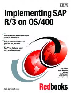


![IBM i 7.1 Technical Overview with Technology ... - IBM Redbooks [PDF]](https://m.moam.info/img/260x300/ibm-i-71-technical-overview-with-technology-ibm-re_647a5748098a9eae448b4612.jpg)

![IBM Sterling Managed File Transfer Integration with ... - IBM Redbooks [PDF]](https://m.moam.info/img/260x300/ibm-sterling-managed-file-transfer-integration-wit_647ce6e0098a9e603c8b460f.jpg)


