Control Eng. Practice, Vol. 5, No. 8, pp. 1137-1 i 44, 1997 Copyright © 1997 Ehtevie¢ Science Lid Printed in Great Britain. All righ~ reserved 0967-0661/97 $17.00 + 0.00
Pergamon PII:S0967-0661(97)00107-X
IDENTIFICATION AND CONTROL OF NONLINEAR ACTIVE PNEUMATIC SUSPENSION FOR RAILWAY VEHICLES, USING NEURAL NETWORKS M. Nagai*, A. Moran*, Y. Tamura* and S. Koizumi** *Tokyo Universityof Agricultureand Technology,Koganei-shi,Naka-machi2-24-16,Tokyo 184, Japan (
[email protected]) **SumitomoMetalIndustries Co. Ltd, Osaka,Japan
(Received March 1997; in final form June 1997)
Abstract: This paper analyzes the performance of neural networks for the identification and optimal control of active pneunmtic suspensions of high-speed railway vehicles. It is shown that neural networks c n be d]iciently trained to identify the dynamics of nonlinear pneumatic suspensions, as well as being trained t o work as (sub)optlmal nonlinear controllers. The performance of the nonllnesr suspension with the neuro-controUer is compared with the performance of the suspension with an LQ controller designed after llnearizing the suspension components around the equih'brium point. Copyright © 1997 Elsevier Science Ltd
Keywords: Active vehicle suspension, neural networks, nonlinear models, nonlinear control, pneumatic systems
1. I N T R O D U C T I O N
damper modal and modern linear control theory are proven efficient tools for active suspension design (Nngai, 1993). However, controllers designed using approximated linear suspension models present performance and robustness limitations when applied to an actual pnenm~tic suspension with a nonlinear spring, damper and actuator. Full consideration of these nonlinearities is regarded as essential for further enhancement of the performance of active suspensions (Nagai, 1993).
Effective control of the vibration of vehicle suspensions, which increases with running velocity, is essential in order to guarantee running stability and ride comfort of high-speed railway vehicles. In order to deal with this issue, several passive and actire control methods have been proposed and analyzed. The analysis reveals that passive methods are unable to reduce the vibration of the suspension across the whole frequency range, and that active control methods are, on the other hand, very efficient at improving the vibration-isolation performance of the suspension (Moran and Nagai, 1991; Hrovat 1993).
In recent years, the application of artificial neural networks to the design of controllers for nonlinear systems has been widely studied for its potential to provide better performAnr~ than linear control approaches, given its ]earning and self-tuning abilities, as well as its nonlinear optlmiT~ation capabilities. Several reports show that neural networks can be efficiently trained to identify the dynamics
Design of conventionalactive suspensions has been based on linear models formulated by linearizing the suspension components around the equilibrium point. For linear models, the s~-hook 1137
1138
M. Nagai etal.
Ks2
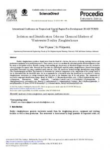
[1]Vibrator [2]Air spring [3]Pneumatic a c t u a t o r [4]Accelerometer [5]Potentiometcr [6]Sprung mass Fig. 1. One-degree-of-freedom experimental suspension.
of nonlinear systems, as well as trained to perform as nonlinear controllers. Several neuro-controller structures and several training methods have been proposed and analyzed (Moran, 1994; Nguyen and Widrow, 1991). This paper presents a nonlinear approach, using the theory of neural networks, to cope with the nonlinearity of the pneumatic suspensions in order to enhance the performance of active control. A full-size experimental suspension system of one degree of freedom, equipped with an air spring and a pneumatic actuator, has been constructed to verify the effectiveness and practical applicability of neural networks for identification and control of nonlinear systems. To design the neurocontroller, first, the dynamics of the experimental system was identified by a neural network; then this neural-network model was used to train the neuro controller to minimize a given cost function (Moran and Nagai, 1993a). The performance of the active suspension with neuro-control is compared with the performance of an active suspension using traditional LQ controllers. 2. L I N E A R M O D E L O F PNEUMATIC SUSPENSION The experimental one-degree-of-freedom pneumatic suspension is shown in Fig. 1, and its equivalent linear model is shown in Fig. 2. The equation describing the vertical motion of the vehicle body (sprung mass) is: m
=
+
(1)
~
Actuator
Fig. 2. Linear one-degree-of-freedom suspension model.
where xl denotes the vertical displacement of the vehicle body, m the mass of the body, Fs the air spring force, and F~ the pnenmatic actuator force. The linearized dynamic characteristics of the air spring are described by the following equation: ~6s
_
k,l(1 + N ) F s _ (ksl + ks2)AS~l (2) c ksl [ks2 + -]V(ksl + ks2)] A x 1 c
where ks1 and ks2 are spring coefficients, c is the equivalent damping coefficient and AXl = Xl - Xo is the suspension deflection. The linearized dynamic characteristics of the pneumatic actuator and the electro-magnetic valve can be described by the following equations F~ -
-
~/RTokxF,~ + ~/AsTok2 v0 v0
-
-
-
. = bo
-
(% -
v
27A~Po - AXl vo (a)
Ap)
(4)
where As, Vo, P0 and To are the cross-sectional area, the volume, the internal pressure and the chamber temperature of the pneumatic actuator, respectively; ~/ is the specific heat of air, R is the air thermodynamic constant, k, and /o2 are flow constants, b0 is the gain of the control valve, kp is a pressure-to-voltage conversion constant, v the control quantity of the orifice of the electromagnetic valve, Ap the pressure difference between actuator chambers, and up is the control input of the valve. Table 1 shows the values of the parameters of the experimental suspension. Equations (1) to (4) can be combined to formulate the linear model of the pneumatic suspension, which in discrete time is expressed as follows: x(k + 1) = A x ( k ) + B
Ak) + W w ( k )
(5)
Nonlinear ActivePneumaticSuspensionUsing Neural Networks where w = Xo denotes the irregularitiesof the railway, which excite the suspension. A and B axe the state and input matrices. The state vector x is defined as X :
[Xl , ~1,
AXl,
A~] T
•
(6)
This linear system can be optimally controlled by the state feedback ~p=--flXl
-- f 2 X l
-- A Z l
--
f4Ap
(7)
where the feedback gains fl , ~ = 1,... ,4 axe calculated using LQR theolT considering the following cost function: M
1 J : 2M ~
[PlXl(k)2 + Pa Axl (k)2 + %~(k- 1)2 ]
1139
where @ is a vectorial nonlinear function (Moran and Nngal, 1994). Using some previous knowledge available about the suspension system it is possible to formulate some particular structures for O. For example, it could be assumed that the nonlinear state-equation (9) can be decomposed into its linear and nonlinear parts: x(k + 1) : Ax(k) + B ~ ( k ) + W~0(k) + #(x(k), u,p(k), ~v(k))
(10) or decomposed into a known nonlinear part or an unknown nonlinear part. In order to improve the control performance when using neuxal networks, it is recommended to use any previous knowledge to formulate the models and design the controllers
(Yasnl, ct al., 1996).
k=l
(s) where Pl and Pa axe weighting factors. The cost function of Eq. (8) includes the verticalacceleration of the vehicle body zl, related to ride comfort,the suspension stroke Axl, related to nmning stability,and the control effort% which should be kept at physically realizablevalues.
Table i. Baseline paxameters of the experimental suspension m k,1
6793.0 ~kg] 0.773x10s [N/m]
k.2 0.0 [N/m] N c "y R
0.9453 3.4774xi0s [N.sec/m] 1.4 2.87x10² [J/kg.K]
As
7.854x10 [m2]
Vo P0
3.927x10 -4 [ms] 2.94x10 s ~Pa]
To
298 [K]
kl k2 b0
2.341x10 -s [m.sec] 6.884x10² [N.sec/m3] 4.5x10 - s Ira2/V]
3. N O N L I N E A R (SUB)OPTIMAL CONTROL USING NEURAL NETWORKS Equation (5) represents a lineaxized model of the suspension, which does not include the actual nonlinear chaxacteristics of the pneumatic suspension. In a general folln, the nonlinear dynanfics of the pneumatic suspension can be represented by the following nonlinear equation model, which has the same states and inputs as the lineax model x(k + 1) : @(x(k), %(k), ~v(k))
(9)
In this study, the nonlinear relationship of Eq. (9) will not be described by mathenmtical expressions, or decomposed in linear or nonlinear parts, but it is assun~d to be an unknown function, to be identiffed by a neuIal network. The identified neural model of the suspension (subsequently referred to as the "neuro-vehicle") is represented by a trained neural network, which consists of 4 layers, i.e., the linear input and output layers, and two hidden layers with neurons having sigmoid functions. The number of neurons for each layer are: 6 in the input layex, including the four state variables of Eq.(6), the railway disturhance ~n, and the control input up, 4 neurons in the output layer, representing the four state variables, and 10 neurons in each hidden layer. The training of the neural network is Cal~ied out by the dynamic back-propagation algorithm, reducing the sum of the squaxe of the errors of the variables to a certain level (Moran and Nagai, 1993b). Although a neural network with only one hidden layer of nonlinear neurons could be selected for neuro-identiffcation, experience shows that neural networks with two hidden layers of nonlinesx neurons provide more flexibility and require less training data to achieve similar performance than networks with one hidden layer. Several studies have theoretically shown the superiority of fou~-layered feedforwaxd networks over three-layered networks in terms of the number of parameters needed for the training data (Tamum and Tateishi, 1997). The block diagram for the training of the neurovehicle is shown in Fig. 3. In this figure it can be noted that the state inputs of the neuro-vehicle could come ~om (A) the outputs of the actual vehicle, or (B) the outputs of the neuro-velficle itself. Vqhile in the former case the neuro-vehicle does not possesses d y n a ~ , in the latter case the neuro-vehicle performs as a true dynamic system with recurrent characteristics. Although the training of neural networks with dynamic characteristics is more demanding in terms of computation and time than neural networks without dyna-
1140
W(k)
M. Nagai et aL
Actual
)
iV(k) ]~+]+
~k+l)
~
3'
7__1 r I Vehicle I
^
B",. +J
r I
Neuro Vehicle
I
"~ X(k+l)
Fig. 3. Block diagram for training the neural network for identification (neuro-vehicle).
we,)
Actual '" l'~(k+l)
,,eh...°, J Augmented
Vehicle l !
C.,o~b'oller
8",
......... .~ .........................
X(k)
:
:
: Function :
, . . . . . . . . . . . .
•
, . . . . . . . . . . . .
J
A:Forwardlearning B:Reourrentlearning Fig. 4. Block diagram for training the neural network for control (neuro-control).
mics, dynamic neural networks are more powerful than static networks and can identify the true dynamics of systems more accurately. In this study, a dynamic neuro-vehiele model is used to identify the dynamics of the actual pneumatic suspension. After the training of the neuro-vehicle, a nonlinear feedback control law, which can in general be expressed as Eq. (11), is introduced for control purposes (Moran and Nagai, 1993b):
~ = ~(~1, ~1, Azx, Ap)
(11)
where ~ is an scalar nonlinear function with vectorial input. This control law is realized by a four-layer neural network (subsequently referred to as the "neuro-controller') with linear input and output layers and two hidden layers with neurons having sigmoid functions. The number of neurons are: 4 in the input layer, representing the state variables, 5 in each hidden layer, and I in the out-
put layer as the control input ah~. The training of the neuro-controller is carried out by using the dynamic back-propagation algorithm, and considering the nonlinear dynamics of the pneumatic suspension previously identified by the neuro-vehicle model (Moran, 1994). Figure 4 shows the block diagram for training neuro-controllers. In this figure it can be noted that forward learning corresponds to the situation where the outputs of the actual suspension are used as controller inputs and also as state inputs of the neuro-vehicle (static network), and that recurrent lazrning corresponds to the situation where the outputs of the neuro-vehicle are used as inputs of the neuro-controller and also as state inputs of the neuro-vehicle (recurrent network). It is important to say that in order to facilitate the training of the neuro-vehicle and of the (sub)optimal neuro-controller, they were first trained to identify the linear model of Eq. (5), and the linear controller of Eq, (7), respectively. Posteriorly, the neuro-vehicle was trained to identify the true nonlinear dynamics of the pneumatic suspension, and the neuro-controller was trained, using this neuro~vehicle model, to minimize the co~t function of Eq. (8). The training of the neurovehicle and neuro-controller was carried out offline using a NF~C personal computer with a 150 MHz processor. The training of the neuro-vehicle took about 3 hours, and the training of the neurocontroller took less than 20 minutes. Longer training times did not yield significant reductions in the value of the cost function being minimized.
4. E X P E R I M E N T A L
SYSTEM
3. I Outline of the ezperimental system The set-up and specifications of the experimental system are shown in Fig. 1 and Table 1, respectively. As shown in Fig. 1, the pneumatic actuator and the air spring are placed in parallel with each other between the vehicle body and the hydraulic vibrator which simulates the guideway irregularities. The air pressure inside the actuator is controlled by two electro-magnetic valves, by way of pulse-width-modulation. The pressure is measured by two pressure gauges. The vertical acceleration of the vehicle body is measured by an accelerometer, and the relative displacement Axl is measured by a potentiometer. These three signals are input to a personal computer through an A/D converter. The control signal is then calculated, based on either the linear (LQ) or nonlinear (neuro) control law, and is output through a D/A converter to control the electro-magnetic valves.
Nonlinear ActivePneumaticSuspension Using Neural Networks
0.1
............ i...............
1141
the natural frequency of the suspension, is also added to the irregularities for training purposes. Figure 6 shows the PSD of the guideway irregularities.
............. , ................... i .................. ; ..................
5. R E S U L T S A N D D I S C U S S I O N 2
4
t[sec]
6
8
10
12 5. I N e u r o - i d e n t i f i c a t i o n
Fig. 5. Time history of guideway irregularities ~o.
xlO "~
i
i
l
i
;
"
!
of nonlinear
dynamics
Figure 7 compares the time history of the suspension stroke Azl of the identifiedneuro-vehicle with that of the actual suspension. It is apparent that the two responses show very good agreement, which indicates that the nonlinear dynamics of the pneumatic suspension has been well identified by the neuro-vehicle.
2.5
2 • .[I[.--+ ~'~...,1.5 I
i
!
..........~....................... , . . . . . . #. . . . . . ~
............. ............... i ........................
i ..........
i .....................
..............
1 i ~ 1 ;....... _;........... ~......... , . . . .
1 ! & .......... • .....
0
4
12
0.5
2
6
$
10
14
Fr~,y[Hz] Fig. 6. Power spectral density of guideway irregularities Xo.
The control sampling time was selected as 20 ms in consideration of the fact that the frequencies of interest of railway vehicle suspensions are lower than 10 Hz.
J. ~ G e n e r a t i o n
of rs~utom
disturbances
In order to evaluate the effectiveness of neurocontrol, the frequency responses of the vehicle body acceleration ~1, and the control input up are analyzed when the experimental suspension system is excited by random guideway irregularities x0. The power spectral density (PSD) of the irreg-larities used in the experiments is expressed as follows: C PSD(w)
=
w 2 + w ~°
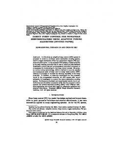
In order to examine the nonlinear characteristics of the suspension, three kinds of sinusoidal disturbances x0 with amplitudes of lmm~ 3ram and 6mm~ respectively, are applied to the suspension. Figure 8(a) shows the gain of the experimental frequency response of the acceleration ~1 of the vehicle body when the suspension is excited by sinusoidal disturbances. It is clear that, unlike linear systems, the frequency response of the nonlinear suspension is dependent on the amplitude of the external disturbance. Figure 8(b) shows the frequency response of the acceleration xl calculated from the output of the neuro-vehicle under the same conditions as those in Fig. 8(a). A comparison between the results of Pigs. 8(a) and (b) shows that the responses of the actual pneumatic suspension and neuro-vehicle are simllar, and that the response of the neuro-vehicle also depends on the amplitude of the disturbances x0, verifying the fact that the nonlinearities of the actual suspension have been identified by the neurovehicle. Around ? Hz, there is a small discrepancy between the experime~rtal and neuro-vehicle responses, which is more pronounced for small am-
2
- ---
Experiment Neuro-identlflcation
0 (12)
where C and Wo are parameters depending on the characteristics of the railway and the running velocity of the vehicle. The irregnlaTities are generated by filtering white noise through a low-pass filter. Figure 5 shows the time history of the irregularities used for' the training of the neurocontroller. A sinusoidal wave of 1.2 Hz, which is
-2
0
1
2
3
4 "rime (sec)
Fig. 7. Time history of suspension stroke Axl.
1142
M. Nagai et al.
(
a
)
~
p
e
n
'
m
~
considering the fact that controllem of pneumatic suspensions of railway vehicles have bandwidths less than 5 Hz, the neuro-vehicle has been especially trained to identify the nonlinear dyoamics of the pneumatic suspension at frequencies lower than 5 Hz.
.
ld
5. 2 Nonlinear optimal control by neural networks
:z12 /6~'~/ ~'"
i
10
I
.c:
-
!
1 mm
/
111 f~
/
10
Figure 9 shows the time history of the vertical acceleration 21 of the vehicle body for the case of active suspension with neuro-control, and the case of passive suspension. Comparing these two responses, it is obvious that the acceleration for the case of neuro-control is significantly reduced, which represents improvement in ride comfort.
1 mm 3mm - - - - 6 mm -- --
/,/'
3mm 6 mm - -
I
~
0.5
1
I
--
l
Frequency
5 (Hz)
10
Fig. 8. Frequency reponse of acceleration Xl for different amplitudes of guideway disturbances.
t ^~
....
0
i
i
t
;/\
:/4
,
,
. . . . . . . . . .
\l
.
.
.
j'~
t~
:',:,, .
.
.
.
,:
.
....
"'J
'~,j
Neuro-conlrol Passive
---
-1 0
1
2
Time
,'
3
(sec)
Figures 10(a) and (b) compare the time history of the acceleration Xl and control input up for the cases of neuro-control and LQ control. According to these results, it is clear that although the amplitude of the acceleration for neuro control and LQ control turn out to be similar, the amplitude of the control signal for neuro-control is lower than for LQ control. This fact indicates that neuro-control consumes less energy than LQ control to achieve the same control performance. This characteristc of neuro-control is also shown in the frequency response of the acceleration Xl and control signal up shown in Figs ll(a) and (b), respectively. From Fig. ll(a) it is noted that, although neuro-control presents a somewhat smaller gain at low frequencies, and a somewhat bigger gain at medium frequencies than LQ control, no striking difference is observed in the frequency response of the acceleration 5~1 for neuro-control and LQ control. On the other hand, in Fig. ll(b) it is noted that the amplitude of the control input u r for neuro-control is much lower than the amplitude for LQ control. This reduction indicates that the required capacity of the actuator can be reduced for active suspensions with neuro-control, which may bring great practical benefits.
4
Fig. 9. Time history of acceleration ~1 for the suspension with neuro-control and passive suspension (no control).
plitudes of the sinusoidal disturbances. This discrepancy can be explained by some stiction effects in the experimental suspension that were not identiffed by the neuro-vehicle. This discrepancy could b e reduced (or eliminated) by training the neurovehicle considering external disturbances Xo lmvbag rich frequency components around 7 Hz. However, since the purpose of the neurc~vehicle is to be used for training the neuro-controller, and also
Figure 12 shows the PSD of the vehicle body acceleration xl when the suspension is excited by random disturbances x0 with PSD given by Eq. 12. It can be noted that the vibration performance of the suspension is improved in the case of neuro-control compared with the cases of LQ control and the passive suspension, especially around the resonant frequency of the suspension (0.8-1.2 Hz). The deterioration observed around 5 Hz for neuro-control and LQ control may be caused by delays of the electro-magnetic valves or other factors. However, since in practical situations the guideway disturbances are especially strong in the low-frequency range, this deterioration is not a serious concern.
Nonlinear Active Pneumatic Suspension Using Neural Networks N "I-
(a)'rim~ lutory of car accdenttion • /Xl #,~
%..10
~
|
•
.
.
.
.
,."l,
.
. .
.
.
.
.
.
.
.
.
.
.
3
['~.
%
' 0
..
|
q,"
....
Neuro-oonlrol
-----
L Q conlrol
- ' - - Passive
E o . . ,
!
:X
V
1143
,
"
0.
-I
0
/
,
0.5
(b)Tmmhistory of control dgnal
1 Frequency
5
(Hz)
10
0.
:A '1
0
~
I
,,
II
t I
,1 PJ t
12. Comparison of the PSD of the vehicle acceleration for nearo-control, LQ control and .passive suspension.
.,,t
o-
"~'%~I ...................... ~ll ~ !o~tl~i l,. ..~I. I~l
---
-I
v"
Nefizo.conlrol LQ control
0
2
1
",
-rime
I ;-
U
3
(sec)
4
Fig. 10. Comparison of the response of the suspension with neum-control and LQ control.
Computing the values of the cost function of Eq. (8) for the suspension with neuro-control and LQ control, it is found that the cost function for neuro-control is between 15% to 20% lower than for L Q control The bigger reductions in the mini m u m value of the cost function are obtained for the situation when the suspension is excited by the same disturbances x0 used for training the neuro-controller. As the nonlinearitiesof the system are stronger,the benefitsof neuro-controlover L Q control become more evident.
(a)Carbodyaccele~ration. 6. C O N C L U S I O N S 10
:;q7 5
cy Iy
(3 10
Neuro-control ---- LQ ¢onlrol
I
I
I
(b)Comrolsignal. 108
\ ,i
c-
10 7
/ /// I
0.5
/
t
l I
~
o I --- - 1.0 conlrol
This paper proposes a nonlinear optimal control method to improve the ride comfort of pneumatic suspensions of high-speed railway vehicles using nettzal networks. A one-degree-of-freedom full-size experimental suspension system was constructed to examine the effectiveness of the proposed control method. The main results obtained can be snmm~rized as follows: 1) Neural networks can identify the nonlinear dynamics of the pne-m~tic suspension, which depends on the amplitude of the external disturbances. 2) Compared with LQ control, neum-control provides better performance in the low-frequency range, while cons, ruing less energy, which is certainly related to the ability of neum-controllers to cope with the nonlinearities of the suspension.
I
1 Frequency 5
(Hz)
10 REFERENCES
Fig. ii. Comparison of the frequency response of the suspension with neuro-control and L Q control
Hrovat, D. (1993). Applications of optimal control to advanced automotive suspensions.
T~n.~adiona of ASME, Jourmd of D ~ m i c Systems, Measurement ami Coatrol, VoLll5, No.2(B), pp.139-142.
1144
M. Nagaiet al.
Moran, A. and Nag&i, M. (1991). Analysis and . design of active suspensions by Hoo robust control theory. JSME International Journal, Series III, VoL35, No.3, pp.427-437. Moran, A. and Nag&i, M. (1993a). Optimal rear suspension preview control of nonlinear vehicles using neural networks. Proc. of l~th IFAC World Congress, Sydney, Australia, VoL3, pp.139-142. Moran, A. and Nag&i, M. (1993b). b-~cient online traning of recurrent networks for identification and optimal control of nonlinear systems. Proc. Internat. Joint Conf. on Neural Nehnorks, IJCNN'9$, Vol.2, pp.1789-1792. Moran, A. and Nag&i, M. (1994). Optimal active control of nonlinear vehicle suspensions using neural networks. JSME International Jourha/, Series C, VoL37, No.4, p.707. Moran, A. (1994). Identifimtion and control of nonlinmr vehicle dynamics using neural networks. Doctoral thesis. Tokyo University of Agric. and Technology. Tokyo, Japan.
Nag&i, M. (1993). Recent researckes on active suspeusiom for g r o u d ve~cks. JSME l~terMtio~d 2om'Ml, Series C, Vol.36, No.2, pp.161193. Nguyen, D. and Widrow, B. (1991). Neural networks for self-leLrning control system. I~. Journal of Control~ VoL54, No.0, pp.14391454. Tamur& S. sad Tateiski M. (1097). Cal~bili£ies of a four layered feedforward hemal network: four layers versus three. IEEE T m ~ a c t i o ~ on Neum/Ne~l~d:a, VoL8, No.2. Yasui T., Morffi= A. aad H&y~e M. ( 1 ~ ) . httegr&tion of lhte~ lystems sad meural met_ works for output feedback coatrol of nouvibratiou systems. Prec. of T/ti~ Motion and Vilmttion Co~rol Concrete, MOVIC'96, Chiba, Jslma, Vol.2, pp.98-103.