Available online at www.sciencedirect.com
ScienceDirect Energy Procedia 81 (2015) 1143 – 1150
69th Conference of the Italian Thermal Machines Engineering Association, ATI 2014
A nonlinear control strategy for finite-amplitude perturbations in a boundary-layer flow S. Cherubinia, J.-C. Robineta, P.De Palmab,* a
DynFluid Laboratory, Arts et Metiers ParisTech, 151, Bd. de l'Hopital, 75013, France b DMMM, CEMeC, Politecnico di Bari, via Re David 200, 70125 Bari, Italy
Abstract The present work describes an optimal control strategy, based on the full Navier-Stokes equations, aiming at hampering the rapid growth of unsteady finite-amplitude perturbations in the Blasius boundary-layer flow. An optimization strategy is used to find the blowing and suction control law at the wall providing the maximum damping of the perturbation energy at a given target time. Two optimally-growing finite-amplitude initial perturbations have been employed to initialize the flow. The nonlinear control procedure can drive such perturbations back to the laminar state, provided that the target time of the minimisation and the region in which the blowing and suction is applied have been suitably chosen. On the other hand, an equivalent control procedure based on the linearized Navier-Stokes equations is much less effective, being not able to lead the flow to the laminar state when finiteamplitude disturbances are considered. © 2015 The Authors. Published by Elsevier Ltd. This is an open access article under the CC BY-NC-ND license © 2015 The Authors. Published by Elsevier Ltd. (http://creativecommons.org/licenses/by-nc-nd/4.0/). Peer-review under responsibility of the Scientific Committee of ATI 2014. Peer-review under responsibility of the Scientific Committee of ATI 2014 Keywords: optimal perturbations; transition; blowing and suction
1. Introduction The capability of controlling the flow in gas-turbine engines has a significant impact on the design of modern systems for energy production and propulsion. In fact, the reduction of fuel consumption and carbon dioxide emissions have stimulated researchers to find solutions to reduce friction losses using active (such as flow jets and plasma actuators) or passive (such as vortex generators or roughness elements) control devices [1, 2], which may
* Corresponding author. Tel.: +39-080-5963226; fax: +39-080-5963411. E-mail address:
[email protected]
1876-6102 © 2015 The Authors. Published by Elsevier Ltd. This is an open access article under the CC BY-NC-ND license (http://creativecommons.org/licenses/by-nc-nd/4.0/). Peer-review under responsibility of the Scientific Committee of ATI 2014 doi:10.1016/j.egypro.2015.12.139
1144
S. Cherubini et al. / Energy Procedia 81 (2015) 1143 – 1150
open the way to innovative design solutions. For example, a typical problem is the control of the separation bubble in low-pressure gas turbines by a suitable setting of the transition point along the suction side of the blade [3, 4], which can be achieved by studying the stability range of the separation bubble at wall [5]. The present work deals with the control of the transition from the laminar to the turbulent state in a boundary layer using blowing and suction flow at the wall. Most of the recent methods for designing compensators aiming at delaying or hampering transition in a boundary-layer flow are based on linear models [6]. The applicability of such linear strategies is based on the hypothesis that linear models can accurately represent the input-output dynamics of the transitional flow. However, very recent studies have assessed the importance of nonlinear effects in the transition process [7-9] and in particular Cherubini et al. [9] have shown that non-linearity is crucial to sustain the growth of the energy for the case of “optimal perturbations” (namely, those perturbations having maximum growth). Very few non-linear strategies for controlling transition in shear flows have been proposed in the past, mostly due to the complexity of the problem of finding reduced-order models capable to account for the whole system dynamics. To overcome this difficulty, some authors have used a full-state approach based on the non-linear Navier-Stokes equations [10,11]. In this work, we extend such a full-state non-linear optimal control approach to the case of a three-dimensional boundary-layer flow [12]. An optimal perturbation is superposed on the Blasius flow; in the absence of a control strategy, due to the very rapid energy growth of such a perturbation, the flow would reach the turbulent state. Our tasks are: i) to identify physical mechanisms controlling the energy growth of the optimal perturbation; ii) to assess the influence of the non-linear terms on the effectiveness of the control procedure; iii) to study the effect of the localisation of the blowing and suction disturbance at wall. 2. Problem formulation 2.1. Governing equations and numerical approach The behavior of a three-dimensional incompressible boundary-layer flow is governed by the Navier–Stokes (NS) equations:
ut + (u ⋅ ∇) u = −∇p +
1 2 ∇u Re
∇⋅u = 0 where u is the velocity vector and p is the pressure term. Dimensionless variables are defined with respect to the inflow boundary-layer displacement thickness, δ∗, and the freestream velocity, U∞, so that the Reynolds number is Re = U∞δ∗/ν, ν being the kinematic viscosity. A computational domain having dimensions equal to Lx = 200, Ly = 20 and Lz = 10.5, x, y and z being the streamwise, wall-normal and spanwise directions, respectively, has been employed. The Blasius base flow is obtained by integrating the NS equations with periodic boundary conditions in the spanwise direction (for further details about the boundary conditions, see [12]). The NS equations are discretized by a finite-difference fractional-step [14] with second-order-accurate space discretization. After a gridconvergence analysis, a mesh made up by 901 × 150 × 61 points – clustered towards the wall so that the thickness of the first cell close to the wall is equal to 0.1 – has been selected. 2.2. Nonlinear control The nonlinear behavior of a perturbation q = (u′, v′, w′, p′)T evolving in a laminar incompressible flow over a flat plate is studied by employing the NS equations written in a perturbative formulation, with respect to the twodimensional Blasius steady state solution, Q = (U, V, 0, P )T . A zero perturbation condition is chosen for the three velocity components at the x−constant and y−constant boundaries, except for the blowing and suction slot, where a Dirichlet condition is imposed for the wall-normal velocity. Periodicity of the perturbation is imposed in the spanwise direction. The aim of the procedure is to prevent the transition to turbulence of a given perturbation, using
S. Cherubini et al. / Energy Procedia 81 (2015) 1143 – 1150
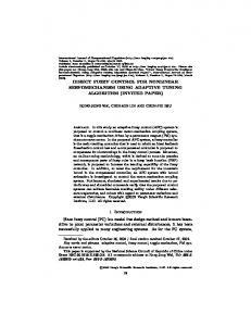
a full-state control strategy based on a direct-adjoint formulation. The actuators are placed at the wall along a streamwise-localized disturbance slot Sw, placed on the flat plate, as shown in Fig. 1, where the blowing and suction law is provided by the wall-normal velocity at the disturbance slot, vw(t). Different configurations of the blowing and suction slot have been considered. Firstly, a single disturbance strip has been placed at seven different streamwise positions in order to study the sensitivity of the blowing and suction law with respect to the initial perturbation: for case 0, 215 < x < 280; for case I, 215 < x < 247.5; for case II, 247.5 < x < 280; for case III, 215 < x < 231.25; for case IV, 231.5 < x < 247.5; for case V, 247.5 < x < 263.75; for case VI, 263.75 < x < 280. Then, five equally spaced disturbance strips have been considered in the zone 215 < x < 280, each one having length lx = 1.5 (case VII). The minimization aims at finding the blowing and suction law of lowest cost providing the lowest disturbance energy at a given target time, T . The disturbance energy is defined as
E(t) =
∫ [u′(t)⋅ u′(t)] dV V
where V is the volume of the whole computational domain. A Lagrange multiplier technique is used [16, 7], aiming at finding the blowing and suction law at the wall, vw(t), minimizing the following functional:
I=
E(T ) 2 T + γ ∫ Ew (t)dt E(0) 0
where the first term at the right hand side is the energy gain of the perturbation, of the control cost, and (see also [11])
Ew (t) =
∫ [v (t)] w
2
γ2
is a parameter setting the weight
dSw
Sw
The Lagrange multiplier technique consists in searching for extrema of an augmented functional, L, with respect to every independent variable. The augmented functional is given by the above objective function plus the following constraints: (a) the perturbation q′ satisfies the three-dimensional incompressible NS equations, written in a perturbative formulation; (b) the shape and amplitude of the initial perturbation superposed to the base flow is given by the initial velocity vector u′0 = (u0′, v0′ , w0′ )T ; (c) the wall-normal velocity at the disturbance slot equals the blowing and suction law found by the minimization (v′ = vw on the disturbance slot) which must have zero net mass flux.
1145
1146
S. Cherubini et al. / Energy Procedia 81 (2015) 1143 – 1150
Fig. 1. Flow configuration.
Integrating by parts and setting to zero the first variation of L with respect to u′, v′, w′, p′, the adjoint equations are obtained. The direct and adjoint equations are parabolic in the forward and backward time direction, respectively, so that they can be solved by a coupled iterative approach, similar to the one used in [15]. The gradient of L with respect to the variable vw is iteratively nullified by using a steepest descent algorithm. Each iteration requires the integration of the three-dimensional NS and adjoint equations forward and backward in time up to the target time as shown in the scheme of Fig. 2. More details about the iterative procedure are available in reference [12].
Fig. 2. Scheme of the direct-adjoint iterative procedure.
3. Results The nonlinear control has been applied to a boundary-layer flow with a supercritical Reynolds number, Re = 610. We aim at controlling impulsive perturbations superposed at the initial time, t = 0, on the Blasius base flow, namely, a linear and a nonlinear optimal perturbation, defined as the perturbations of the base flow which induce the largest energy growth at a given target time, in a linear and a nonlinear framework, respectively. These perturbations have been computed by means of an optimization of the perturbation energy gain using the linearized and the nonlinear Navier-Stokes equations, respectively (see [15, 9]). In both cases, the initial energy of the optimal perturbations is chosen in order to achieve transition, and the control procedure has been used to compute the optimal blowing and suction law achieving the maximum reduction of the perturbation energy at a given target time.
S. Cherubini et al. / Energy Procedia 81 (2015) 1143 – 1150
Fig. 3. Energy gain versus target time T for the nonlinear (left panel) optimal perturbation and the linear (right panel) optimal one, in the uncontrolled case (circles) and in the controlled case 0 with γ 2 = 0.2 (squares).
Figure 3 shows the value of the energy gain versus the target time obtained for both perturbations in the uncontrolled (circles) and the nonlinearly controlled (squares) case, with γ2 = 0.2, using the largest blowing and suction slot (case 0). In the uncontrolled case, one can observe that the NLOP (Fig. 3, left) induces a very large energy gain in a very short time, whereas the LOP (Fig. 3, right) leads to a plateau of the energy value corresponding to the phase of streak saturation. In the controlled case, for both initial perturbations a large decrease of the energy gain is observed for large enough target times, i.e., for T > 50, meaning that the control has to operate on a time scale larger than 50 units to induce a significant effect on the perturbation evolution (a similar behavior has been found in reference [10] for a turbulent channel flow). In particular, for the NLOP the control becomes very effective at large target times, inducing a decrease of one order of magnitude of the energy gain for the largest target time, T = 125. On the other hand, for the LOP, a maximum decrease of the energy gain of a factor 3 is observed. We have also verified that the nonlinear control law is much more effective than a linear one to reduce the energy of finite-amplitude perturbations (see [12]).
Fig. 4. Time evolution of the maximum value of the streamwise perturbation velocity extracted by a DNS initialized by the NLOP for the nonlinear control (left panel) and the linear control (right panel).
1147
1148
S. Cherubini et al. / Energy Procedia 81 (2015) 1143 – 1150
In order to verify if such a reduction corresponds indeed to a laminarization of the flow, we have performed several DNSs in the controlled and uncontrolled cases and analyzed the time evolution of the energy gain and of the maximum value of the streamwise velocity component. The uncontrolled and controlled cases corresponding to three different target times, T = 75, T =100, and T =125, are shown in Fig. 4 (left) for the NLOP. The maximum value of the streamwise velocity component begins to decrease at short times (t ≈ 100). A similar behavior has been observed for the LOP. On the other hand, as shown in Fig. 4 (right), a linear control law is not able to damp such an optimally growing perturbation, even when its amplitude is rescaled to the same value characterizing the blowing and suction profiles of the nonlinear control.
Fig. 5. Energy gain for each configuration of the blowing-and-suction slot (left panel) and corresponding time evolution of the maximum value of the streamwise perturbation velocity (right panel).
Moreover, we analyze the influence of the position and shape of the disturbance strip on the performance of the control. Figure 5 (left) shows the energy gain at target time T = 100 obtained for cases 0 to VII (the black and white rectangles indicating the length of the disturbance strips with respect to case 0 configuration). One can observe that the controlled energy gain changes slightly when the blowing and suction is active in the first half (case I) or in the second quarter (case IV) of the disturbance strip. Whereas, the energy gain strongly increases when the control is applied in the second half (cases II, V, VI) or in the first quarter (case III). This means that the region in which the flow is most sensitive to blowing and suction is the second quarter of the reference disturbance strip (247.5 < x < 280). For this reason, for case VII, the five localized blowing and suction strips have been placed in the second quarter of the reference disturbance slot, namely in the most sensitive zone for the NLOP. The final controlled energy gain is about 2 times that found in the reference case, and 1.5 times the one found in case IV (second quarter).
Fig. 6. Snapshots of the blowing and suction velocity vw at the wall for case 0: nonlinear control (left column) and linear control (right column). Top frames are at t=5; middle frames at t=20; bottom frames at t=40.
S. Cherubini et al. / Energy Procedia 81 (2015) 1143 – 1150
Direct numerical simulations confirm these findings, showing that the flow laminarizes only when the control is applied in the first half or the first quarter of the disturbance strip. The time evolution of the maximum value of the streamwise velocity component is provided in Fig. 5 (right) for cases from 0 to VI, and γ2 = 0.2. One can observe that the umax curves are very close for case I and III, meaning that the disturbance is only slightly affected by the position of the blowing and suction when applied in the first quarter of the disturbance strip.
Fig. 7. Isosurfaces of the Q criterion at t=100 extracted from an uncontrolled DNS initialized by the NLOP.
We analyze now the shape of the blowing and suction law and its effect on the evolution of the perturbation in the flow. We have chosen as reference case the nonlinear control initialized by the NLOP, case 0, with T = 100 and γ2 = 0.2. Figure 6 (right column) provides the contours of vw, extracted at t = 5, t = 20 and t = 40. One can observe localized patches of wall-normal velocity, alternated in the streamwise and spanwise directions, initially showing a quasi circular shape, and eventually turning into Λ structures. For larger times (t > 70) the actuation fades away. Therefore, the control law is very localized in space and time, and it hampers the growth of the perturbation in its first phases. This explains the high sensitivity of the initial perturbation to blowing and suction in the second quarter of the disturbance slot, which is the region where the NLOP is localized at small times (for t < 20). On the other hand, when the optimal control is determined by the linearized Navier-Stokes equations, a very different blowing and suction law has been found. Figure 6 (right column) shows the contours of vw for a linear optimal control computed for the same conditions of the reference case. One can observe that the vw patches lose their localized shape and strongly elongate in the streamwise direction. Such contours are rather similar to the ones recovered for an initial linear optimal perturbation (both for a linear control), even if the shape of the initial perturbation is very different. This means that considering nonlinear effects for determining a control law is crucial when dealing with finite amplitude perturbations, since a linear model would predict an evolution very different from the real dynamics of the perturbation. The analysis of the flow structures indicates that the first effect of the nonlinear control is to try to cancel out the wall-normal finite amplitude perturbation injected within the flow by using an opposite velocity at the wall, similarly to the opposition control technique (see [17] for instance). It also appears that the effect of the vw on the quasi-streamwise vortices is to weaken and stretch them in the streamwise direction, transforming pairs of strong Λ vortices into weak, thin vortices almost aligned with the streamwise direction. This weakening and elongation of the vortices hampers the generation of the hairpin vortex, which is clearly shown at t = 100 for the controlled case in Fig. 7 (left) and the uncontrolled case in Fig. 7 (right). 4. Conclusions In the present work, a full-state optimal control strategy, based on the nonlinear Navier-Stokes equations, is provided, aiming at hampering the rapid growth of finite-amplitude perturbations in a boundary-layer flow. To this end, a Lagrange multipliers technique has been used to find the blowing and suction control law at the wall providing the largest decrease of the energy of a given perturbation at a certain target time. Localized disturbance slots of different lengths have been used to actuate the blowing and suction law. Optimal perturbations, computed by a maximization of the perturbation energy gain in a linearized and fully nonlinear framework, able to lead the flow very rapidly to transition, are used to initialize the computation. The proposed nonlinear control procedure is capable of leading such perturbations back to the laminar state, provided that the target time of the minimisation and the region in which the blowing and suction is applied are chosen to be large enough. When a suitable position of the disturbance slot is chosen with respect to the perturbation, even if the actuator strip is strongly localized, a
1149
1150
S. Cherubini et al. / Energy Procedia 81 (2015) 1143 – 1150
remarkable reduction of the energy gain is obtained. This suitable position can be identified as the high-sensitivity region of the time-evolving perturbation to blowing and suction at the wall. In a real flow configuration, a suitable sensor should trigger the start of the control actuation in order to synchronize the control law with the perturbation. Acknowledgements Most of the computation has been performed on the IBM x3750 (Ada) at IDRIS, Orsay, France (grant i20132a2188). References [1] Bagheri, S., Henningson, D. H., Transition delay using control theory. Phil. Trans. R. Soc 2011; 369:1365–1381. [2] Choi, H., Jeon, W.P., Kim, J., Control of flow over a bluff body. J. Fluid Mech. 2008; 40:113–139. [3] Cutrone L., De Palma P., Pascazio G., Napolitano M., An evaluation of bypass transition models for turbomachinery flows. Int. J. Heat Fluid Flow 2007; 28:161-177. [4] Cutrone L., De Palma P., Pascazio G., Napolitano M., Predicting transition in two- and three-dimensional separated flows. Int. J. Heat Fluid Flow 2008; 29:504-526. [5] Cherubini S., Robinet J.-C., De Palma P., The effects of non-normality and nonlinearity of the Navier-Stokes operator on the dynamics of a large laminar separation bubble. Phys. Fluids 2010; 29:042912PHF. [6] Kim, J., Bewley, T. R., A linear systems approach to flow control. Ann. Rev. Fluid Mech 2007; 39:383–417. [7] Pringle, C. C. T., Kerswell, R.R., Using nonlinear transient growth to construct the minimal seed for shear flow turbulence. Phys. Rev. Lett. 2010; 105:154502. [8] Cherubini, S., De Palma, P., Robinet, J-Ch., Bottaro, A., Rapid path to transition via nonlinear localized optimal perturbations. Phys. Rev. E 2010; 82:066302. [9] Cherubini, S., De Palma, P., Robinet, J-Ch., Bottaro, A., The minimal seed of turbulence transition in a boundary layer. J. Fluid Mech. 2011; 689:221–253. [10] Bewley, T. R., Moin, P., Temam, R., Dns-based predictive control of turbulence: an optimal benchmark for feedback algorithms flows. J. Fluid Mech. 2001; 447:179–225. [11] Passaggia, P.Y., Ehrenstein, U., Adjoint based optimization and control of a separated boundary-layer flow. Eur. J. Mech. B/Fluids 2013; 41:169-177. [12] Cherubini, S., De Palma, P., Robinet, J-Ch, Nonlinear control of unsteady finite-amplitude perturbations in the Blasius boundary-layer flow. J. Fluid Mech 2013; 737:440-465. [13] Bottaro, A., Note on open boundary conditions for elliptic flows . Num. Heat Transfer B 1990; 18:243–256. [14] Verzicco, R. & Orlandi, P., A finite-difference scheme for the three-dimensional in- compressible flows in cylindrical coordinates . J. Comp. Phys. 1996; 123(2): 402–414. [15] Cherubini, S., Robinet, J.-Ch., Bottaro, A. & De Palma, P., Optimal wave packets in a boundary layer and initial phases of a turbulent spot . J. Fluid Mech. 2010; 656:231–259. [16] Zuccher, S., Luchini, P. & Bottaro, A., Algebraic growth in a blasius boundary layer: optimal and robust control by mean suction in the nonlinear regime. Eur. J. Mech. B/Fluids 2004; 513:135–160. [17] Hammond, E.P., Bewley, T. R. & Moin, P., Observed mechanisms for turbulence attenuation and enhancement in opposition-controlled wall-bounded flows . Phys. Fluids 1998; 10:2421–2423.