approximation [17, 22]. .... /s; om ega z1 2, 1/s. 20. 22. 24. 26. 28. 30. -4. -2. 0. 2. 4. 6 x, m y, m. 20. 22. 24. 26. 28. 30. -4. -2. 0 .... Paragraf na Drodze No. 4/(2007).
IDENTIFYING VEHICLE AND COLLISION IMPACT BY APPLYING THE PRINCIPLE OF CONSERVATION OF MECHANICAL ENERGY Stanimir Karapetkov, Hristo Uzunov, Silvia Dechkova Technical University of Sofia, Faculty and College – Sliven
Abstract: Various methodologies and tools applied to identification of vehicle and collision impact seek to present more and more accurate solutions to reproduce, restore, recreate and investigate the casualty. Modern computer technology and software provide the tools to solve specific problems developing mathematical modelling of complex mechanical systems involving vehicles and other objects in a road accident. Scientists generally utilize the Standard Test Method for Impact Testing calculating the energy of deformation of both vehicles, however, one of its limitations is the evaluation of the kinetic energy of the vehicles in post-collision taking into consideration vehicle rotation and linear displacement. To improve the analysis, dynamic traffic simulation is used, taking into account the variations in the coefficient of friction, suspension elasticity and damping. The proposed method is based on a system of two equations derived from two principles: the Principle of Conservation of Mechanical Energy and the Principle of Conservation of Momentum in the impact phase. The new approach is conducted on mathematical modelling and computer simulation of vehicle motion after the impact, wherefrom the linear and angular velocities are analyzed. This is achieved by the numerical solution of the differential equations of motion of the cars after the impact, and the given initial conditions that satisfy the solution are used to solve the system of equations. The main findings of the study can be grouped as follows: 1) Considerably more precise are the positions of the vehicles prior to the moment of first impact and the orientation of velocity vectors after the impact. 2) The variability of the tire-road friction coefficient is taken into consideration. 3) The value of coefficient of restitution according to Newton's theory of impact is unnecessarily determined. 4) According to the applied model of dynamic analysis, accuracy has improved between 60-70% , compared to Delta V method. Keywords: identification, impact, vehicles, MATLAB
1 Introduction Dynamic crash tests are main tasks for expert assessment of road traffic accidents. As a result, the velocity of the centers of mass of the two vehicles is obtained [1, 2, 4, 8, 10, 12, 15, 19]. There are different methods of dynamic analysis, each with certain inaccuracy of the results obtained. The greatest error rate occurs when trying to find the impact, because the velocity of movement of the centers of mass after the impact is determined by the Center-of-Mass Motion Theorem. Vehicles are considered to be material points and the tire-road friction coefficients are estimated. The effect of post-impact vehicle rotation and the resulting angular velocity are not taken into account. It is a wellknown fact that after the crash the vehicle is involved in a significant rotation, each tire continues moving with a relative lateral sliding motion, which is a combination of linear displacement and simultaneous rotation. Due to significant deformations, it is also possible that a wheel might be blocked which would produce a much greater frictional force component compared to the frictional force of the wheel rotation with simultaneous lateral sliding. This movement is subjected to complex dynamic research owing to the fact that the tire-road friction coefficient is practically variable and depends on the speed of the point of contact.
2 Dynamic impact analysis between two vehicles
The most commonly used method of car impact is based on the Law of Momentum Conservation [11, 14, 20, 21], which can be expressed as: ⃗Q = m1 ∙ ⃗V1 + m2 ∙ ⃗V2 = m1 ∙ u ⃗ 1 + m2 ∙ u ⃗2
(1)
where m1 and m2 – masses of vehicles ⃗ 1 and V ⃗ 2 – pre-impact velocities of the centers of mass V of the two vehicles ⃗ 1 and u u ⃗ 2 – post-impact velocities of the centers of mass of the two vehicles. The vector equation is projected on two mutually perpendicular axes, yielding a system of two equations with two unknowns. The post-impact velocities of the centers of mass of both vehicles are derived from the Center-of-Mass Motion Theorem, which can be expressed as: u = √2 ∙ (j1 ∙ σ1 + j2 ∙ σ2 + ⋯ + jn ∙ σn )
(2)
where σi , /i = 1,2, … n/ – is the distance that the center of mass has moved the vehicle. The brake delay along every stretch is determined by the formula ji = [μi ∙ cosαнi ± sinαнi ] ∙ g where
(3)
μi , /i = 1,2/ – tire-road friction coefficient of the particular automobile αi /i = 1,2/ – road inclination angle g – acceleration of gravity
3 Identification passenger cars
of
impact
between
Determining the velocity of the vehicle center of mass following typical errors depends mainly on the correct definition of initial data. It is obvious that errors in the established methods of investigation are mainly made by selecting the tire-road friction coefficient. In practice, the motion is planar, but apart from linear displacement there is a complex dynamics of rotation of a multi-mass system of bodies. Consequently, a new approach to vehicle dynamics has been implemented taking into consideration not only the post-impact linear displacement of the two passenger cars but also their rotation and deformation energy [6]. Integrating equation (1) to the Principle of Conservation of Mechanical Energy, it results in: m1 .V2 1
+
+
2 I1 .ω2 1 2
m2 .V2 2
+
=
2 I2 .ω2 2 2
m1 .u2 1 2
+
m2 .u2 2 2
+
(4)
+ E1 + E2
where: m1 and m2 – masses of vehicles I1 and I2 – mass inertia for the two vehicles around the vertical axis Oz 𝑉1 and 𝑉2 – pre-impact vehicle velocities of the center of mass 𝑢1 and 𝑢2 – post-impact vehicle velocities of the center of mass 𝜔1 and 𝜔2 – post-impact angular velocities of the vehicle bodies around the vertical axis Oz E1 and E2 – deformation energy of car bodies resulting in a crash According to the Law of Momentum Conservation in a two-vehicle impact the analysis includes post-impact velocity of the vehicle center of mass. When designing the equation on two mutually perpendicular axes in the right-hand side of the equation system, the post-impact velocity of the center of mass is present. Its analysis is in compliance with the Center-ofMass Motion Theorem. Typical error of the method is to determine the exact direction of the vehicle motion after the impact. The velocity vector is adopted in the direction of the coordinates of the centers of mass at the moment of impact and the final rest position. In practice, the car performs a sophisticated spatial movement that includes rotation and translation, as well as complex dynamics of tire-road friction. The new approach in the study aims to analyse the post-impact velocity motion of the center of mass, taking into account the macro motion of the multi-mass system, as well as the elasticity of suspension, the damping and the variable nature of the friction coefficient. Improved accuracy of the analysis is achieved by the fact that the vehicle is not considered a
physical point that changes its direction of motion as a result of the impact and the created impulse by the impact force. In addition to the linear motion, the rotation around the vertical axis is also taken into account. The analysis can be used primarily in car-to-car collisions. Car crash study of passenger cars and heavy goods vehicles, when there is a significant difference in masses, is not a matter of the present review.
4 Estimation of deformation energy of vehicle [7, 16] To determine deformation energy, it is assumed that the intensity of the distributed load of the impact forces is a linear function of the plastic deformation and is determined by the formula 𝑑𝐹 = 𝑞 = 𝐴 + 𝐵. 𝑐 𝑑𝑙
(5)
where 𝐹 is the impact force; 𝑐 – value of plastic deformation; 𝐴, 𝐵 – energy coefficients. Energy deformation is derived from 𝛿
𝑐
𝑑𝐸 = [∫ 𝑞ел . 𝑑𝑥 + ∫ 𝑞. 𝑑𝑐 ] . 𝑑𝑙 0
(6)
0
The following equation is obtained 𝑐1 + 2. 𝑐2 + 𝐴 ∙ (+2. 𝑐3 + 2. 𝑐4 ) + 2 +2. 𝑐 + 𝑐 5
6
𝑐12 + 2. 𝑐22 + +2. 𝑐32 + 𝐿 +2. 𝑐42 + 𝐸 = (1 + 𝑡𝑔2 𝜃𝑠 ) ∙ 5 𝐵 +2. 𝑐52 + 𝑐62 + 𝐴2 + ∙ +5∙ +𝑐1 . 𝑐2 + 6 2. 𝐵 +𝑐2 . 𝑐3 + +𝑐3 . 𝑐4 + +𝑐4 . 𝑐5 [ ( +𝑐5 . 𝑐6 ) ]
(7)
The main problems in the dynamic analysis of the obtained system of equations (1) and (4) can be classified in several groups: 1) Correct positions of vehicles on the plane of contact along the approach path prior to the moment of first impact. 2) Correct achievement of vector position of the velocity of the center of mass before and after the impact. 3) The right choice of the tire-road friction coefficients along every stretch. 4) Correct choice of the value of the coefficient of restitution 5) The reading of the variable tire-road friction coefficient when the wheels are rotated around their own axles. 6) Adoption of speed survey approach by use of the Center-of-Mass Motion Theorem.
5 Dynamic analysis of post impact motion of vehicles The new approach is based on mathematical modeling and computer simulation of vehicle motion after impact. This is achieved by the numerical solution of the differential equations of motion of the automobiles after the impact, and the initial conditions that satisfy the solution are used to solve the system of equations (1) and (4). z
1
z
z'
C1
y
1
C
y'
y''
A
z O
1
O
2
2
z'' C2 i
y
O P
2
i
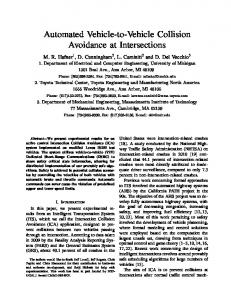
Fig. 1. Rear view of the automobile. According to the method of crash investigation based on mathematical modelling and computer simulation vehicle motion can be reconstructed on the grounds that the found at the accident scene post-crash physical evidence is taken as initial step to set the vehicle positioning at the moment of impact in the first approximation [17, 22]. As a consequence, the positioning of the two automobiles are refined by successive approximations. Finally, dynamics analysis is achieved by solving the differential equations of motion of the vehicles of the form 4
m. ẍ C = ∑[Fix ] + m. g. sinα − wx . √ẋ C2 + ẏ C2 . ẋ C i=1 4
m. ÿ C = ∑[Fiy ] + m. g. sinβ − wy . √ẋ C2 + ẏ C2 . ẏ C i=1 4
m. z̈ C = ∑ Ni − i=1
m. g √1 + tg 2 α + tg 2 β
4
− ∑[β𝑖 . ż ok,i ] i=1
(8)
[JC1 ]. [ω̇] = [MCω ] + [MCa1 ] + [MCa2 ] + [MCγ ] 4
[Iγ ]. [γ̈ ] = ∑[Mγ ] j=1 2
[Iθ ]. [θ̈k ] = ∑[Mkj ] j=1
where 𝑚 - total mass of the vehicle 𝑥𝑐 , 𝑦𝑐 , 𝑧𝑐 - coordinates of the center of mass of the vehicle in relation to the stationary coordinate system 𝐹𝑖 /i = 14/ - frictional forces in the wheels α, β - road surface angles of the longitudinal and transverse slope 𝑁𝑖 /𝑖 = 14/ - normal reaction in the wheels β𝑖 /i = 14/ - damping factor w - drag coefficient
[ω̇] - column matrix of angular acceleration to Euler angles [MCω ]; [MCa1 ]; [MCa2 ]; [MCγ ] - important moment forces [𝐽𝐶1 ] - matrix of the mass inertia of the bodywork related to its invariant coordinate system [𝐽𝛾 ] - square matrix of coefficients of the angular acceleration of the drive wheels, depending on the moment of inertia of the wheels [γ̈ ] - column matrix of the angular accelerations of the wheels when two or four are propulsive [Iθ ] - square matrix of coefficients of the angular acceleration of the drive wheels [θ̈k ] - column matrix of the angular acceleration of the drive wheels In the system of differential equations (4) - a total of 12 equations, specific geometric and inertial properties of mass of each vehicle, elastic characteristics of their suspension, and the parameters of suspension are set. The simulation takes into account the variability of the pressure for each of the wheels in direct relation to the spatial dynamics of the inertial forces and hence the variable nature of the frictional forces. The elements of the matrices are expressed by the generalised coordinates, generalised velocities and generalised accelerations then replaced in the output matrix equations. The differential equation system is solved numerically using a Matlab software or toolbox Simulink. Considering the initial conditions of vehicle motion after the impact, determining the deformation energy for each of the cars and solving the system of equations (1) and (4), the velocities of the centers of mass of the vehicles before impact are obtained. The presented new approach and numerical analysis have some advantages over some mathematical methods of car crash analysis, which can be grouped as follows: 1) Position of vehicles to the impact phase is more precisely determined. 2) Vector orientations of the post-impact velocities of the centers of mass are more accurately determined. 3) The variability of tire-road friction coefficient is taken into consideration. 4) Determining the value of the coefficient of restitution according to Newton's Law of Impact is nonessential.
6 Results A front-impact car accident (Figure 2) has been reconstructed and investigated with known total masses of vehicles and mass moment of inertia parameters [3, 5, 9, 13, 18]. Retrospective accident analysis was performed on damaged areas. Depth of vehicle deformations was recorded in six evenly distributed stretches (Figure 3). The position of the two vehicles at the moment of impact was determined in relation to roadway with centroid and center of mass position in a selected stationary coordinate system. The geometric position of the two cars after the impact is known according to the same coordinate system. Elasticity
coefficient and suspension damping data were taken into account. Initial computational process conditions for differential motion equations (8) have the form of
After the numerical solution of the differential equations of motion using Matlab software tool, Simulink toolbox, the changes in the velocity projections of the centers of mass and the post-impact speeds u1x 0,2m/s; u1y 4,7 m/s; u1 4,04 m/s 14,5 km/h; angular ω1 1,92 s -1 ; for the vehicles in motion are obtained.
u 2x 0,5m/s; u 2y 3,4 m/s; u 2 8,68 m/s 31,2 km/h; ω2 4,5 s -1 . (9) /s; u1y 4,7 m/s; u1 4,04 m/s 14,5 km/h; ω1 1,92 s -1 ;
uC2x , m/s; uC2y , m/s; omega 1 , 1/s
5
z 1
4
3
2
1
m/s; u 2y 3,4 m/s; u 2 8,68 m/s 31,2 km/h; ω2 4,5 s -1 .
1
1
0
-1
0
0.2
0.4
0.6
0.8
1
1.2
1.4
t, s
Fig. 4. Changes in velocity projection of the center of mass and in angular velocity of PEUGEOT after impact. 3
uC2x , m/s; uC2y , m/s; omega 1 , 1/s
2 1 0 -1
2
2
z 2
Fig. 2. Impact process of front-impact car accident
-2 -3 -4 -5 -6
0
0.2
0.4
0.6
0.8
1
1.2
1.4
t, s
Fig. 5. Changes in velocity projection of the center of mass and in angular velocity of RENAULT after impact.
Fig.3. Car body deformations Applying iterations, the initial conditions of the differential equations of motion are established and the solution to the problem of impact according to equations (1) and (2) results in the following data, presented in Table 1: Table 1
6
4
y, m
2
0
Vehicle1 Vehicle 2
Damage width in [m] Angle between velocity direction and the center of mass before impact in degrees of Х
1415,00
980,00
1850,00
750,00
134,00
73,00
116,00
77,00
97,00
83,00
78,00
95,00
-4
20
22
24
26
28
30
x, m
Fig. 6. Position of the two vehicles at the moment of impact and direction of the impact impulse.
6
4
59,00
113,00
21,00
119,00
10,00
20,00
1,29
1,63
2
0
-2
-4
20
22
24
26
28
30
x, m
8,00
173,00
Crash coefficient А in [N/cm]
362,00
316,00
N/cm2]
48,30
49,70
Crash coefficient B in
-2
y, m
Total mass of the automobiles [kg] Mass moment of inertia Jz1 and Jz2 [kg.m2] Deformation depth at the first point of impact C1 in [cm] Deformation depth at the second point of impact C2 in [cm] Deformation depth at the third point of impact C3 in [cm] Deformation depth at the fourth point of impact C4 in [cm] Deformation depth at the fifth point of impact C5 in [cm] Deformation depth at the sixth point of impact C6 in [cm] Angle between the plane normal and the impact force in degrees [o]
Fig. 7. Computer simulation of vehicle motion after impact and direction of the impact impulse.
Table 2 Initial conditions of velocity – u1x and u2x [m/s] Initial conditions of velocity – u1y and u2y [m/s] Initial conditions of angular velocity – 𝜔1 и 𝜔2 [𝑠 −1 ]
7 Conclusions -0,20
-0,50
4,70
3,40
1,92
-4,50
307523 462557
Deformation energy [N.m] Applied friction coefficient
0,60
0,60
Distance from the center of mass [m]
2,55
1,25
Coefficient А [N/cm]
362
316
Coefficient B [N/cm2] Post-impact center of mass velocity according to equation (2) [m/s]
48,3
49,7
5,48
3,84
After solving equations (1) and (4) the following results are obtained: V1x= 20,6 m/s = 74,3 km/h
V1y= 3,5 m/s= 12,5 km/h
V1 = 20,9 m/s = 75,4 km/h
V2x= - 31,7 m/s= -114,4 km/h
V2y= 5,3 m/s= 19,2 km/h
V2= 32,3 m/s= 116,1 km/h
Sx= - 28172 N.s
Sy= 1752 N.s
S=28226 N.s
Test validity of the analysis can be done by applying the Impulse-Momentum Change Theorem for the two cars in the form of: ⃗S = m. 𝑢 ⃗ (10) ⃗ − m. 𝑉 The following vector equation is obtained ⃗𝑗 = 𝑢 ⃗𝑗 , 𝑉 ⃗ 𝑗 − ∆𝑉
𝑗 = 1,2
(11)
A reconstruction model of vehicle impact speed for the center of mass of both cars was built. The comparative analysis is shown in Figure 7 and Fig. 8.
Fig. 8. A reconstruction model of vehicle impact speed incorporating Delta V method.
Fig. 9. A reconstruction model of vehicle impact speed incorporating the principle of conservation of mechanical energy.
1. The dynamic analysis to determine linear and angular velocities of vehicle center of mass includes a set of significantly more precise procedures that take into consideration the variability of the tire-road friction coefficient, the dynamic components of the suspension elasticity and damping. 2. A comparative analysis was carried out to solve the task of impact according to the proposed new approach and to the use of the attributed friction coefficient, as an indicator of the improved accuracy is the comparison of the parallelism of the vectors dV1 and dV2 based on the Impulse-Momentum Change Theorem. In the analysis, the accuracy of the study depends on the parallelism of the two vectors, where the divergence of 6.53° reached 2.12°. 3. The analysis shows that measurements of deformations of both vehicles regarding resultant deformation energy E1 and E2 should take into account maximum plastic deformation. 4. Vehicle impact testing methodology is the most accurate and applicable primarily to passenger cars. In cases of a truck crashes, mass moments of inertia should be well known. It is quite often that heavy trucks experience a significant change in the center of mass as a result of load displacement, which in practice is hard to account for. REFERENCES 1. B. Schmidt, W. Haight, T. Szabo, J. Welcher, “System-based energy and momentum analysis of collisions,” in Accident Reconstruction: Technology and Animation VIII SP-1319, no. 980026, Society of Automotive Engineers, Warrendale, PA, February (1998). 2. D. Sharma, S. Stern, J. Brophy,“An Overview of NHTSA’s Crash Reconstruction Software WinSMASH.” In Proceedings of the Twentieth International Conference on Enhanced Safety of Vehicles, Paper No. 07-0211, Lyon, France, (2007). 3. D. Vangi, Simplified Method for Evaluating Energy Loss in Vehicle Collisions. Accident Analysis and Prevention, 41/(2009). 4. J. Daily, N. Shigemura, J. Daily, Fundamentals of Traffic Crash Reconstruction. Jacksonville, Florida: Institute of Police Technololgy and Managment, University of North Florida, (2006). 5. J. Neptune, G. Blair, J. Flynn, “Amethod for quantifying vehicle crush stiffness coefficients,” SAE Technical Paper Series, no. 920607, 1992. 6. J. Wicher, Energetyczne metody analizy Scientific and Educational Conference “Development of automotive engineering versus motor insurance”, Radom (2006). 7. K. Campbell, “Energy basis for collision severity,” SAE Technical Paper Series, no. 740565, (1974). 8. K. Prasad, “CRASH3 Damage Algorithm Reformulation for Front and Rear Collisions.” SAE 900098, (1990).
9. L. Campbell, Energy Basis for Collision Severity. SAE Paper 740565, (1974). 10. L. Stucki, O. Fessahaie,“Comparison of Measured Velocity Change in Frontal Crash Tests to NASS Computed Velocity Change.” SAE 980649, Society of Automotive Engineers, (1998). 11. M. Nolan, A. Preuss, L. Jones, B. O’Neill,“An Update on Relationships between Computed Delta-Vs and Impact Speeds for Offset Crashes.” In the Proceedings of the Sixteenth International Technical Conference on the Enhanced Safety of Vehicles (Windsor, Canada, June 1998), Paper No. 98-S6-O-07, (1998). 12. P. Hight, D. Kent-Koop, R. Hight, “Barrier equivalent velocity, delta v and CRASH3 stiffness in automobile collisions,” SAE Technical Paper Series, no. 850437, (1985). 13. P. Niehoff, C. Gabler, “The Accuracy of WinSMASH Delta-V Estimates: The Influence of Vehicle Type, Stiffness, and Impact Mode.” In the 50th Annual Proceedings of the Association for the Advancement of Automotive Medicine. Chicago, IL, (2006). 14. R. Hibbeler, Engineering Mechanics: Dynamics. Upper Saddle River, NJ: Prentice Hall, 10th ed., (2004). 15. R. Mchenry, G. Mchenry, A Revised Damage Analysis Procedure for the CRASH Computer Program. SAE Paper 861894, (1986). 16. R. Owsiański, Szacowanie energii deformacji nadwozi kompaktowych samochodów osobowych (Estimation of the bodywork deformation energy of compact passenger cars). Paragraf na Drodze No. 4/(2007). 17. T. Jiang, H. Grzebieta, G. Rechnitzer, S. Richardson, X. Zhao, Review of Car Frontal Stiffness Equations for Estimating Vehicle Impact Velocities. The 18th International Technical Conference on the Enhanced Safety of Vehicles Conference (ESV), Nagoya, (2003). 18. W. Stronge, Impact Mechanics. Cambridge: Cambridge University Press, (2000). 19. W. Wach, Analiza deformacji samochodu według standardu CRASH3. Część 2: Pomiar głębokości odkształcenia (Analysis of motor vehicle deformation according to the CRASH3 standard. Part 2: Measurement of deformation depth). Paragraf na Drodze No. 12/(2003). 20. S. Karapetkov, Auto Technical Expertise, Technical University - Sofia, Bulgaria, (2005). 21. S. Karapetkov, Investigation of road traffic accident, technical commentary on the lawyer. Technical University of Sofia, Bulgaria, (2010). 22. S. Karapetkov, H. Uzunov, Dynamics of transverse resistance of a car. Didada Consult – Sofia, Bulgaria, (2016).