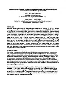
Journal of Radioanalytical and Nuclear Chemistry, Vol. 263, No. 1 (2005) 159–164
NUCLEAR TECHNIQUES IN NATIONAL SECURITY STUDIES ON CONTRABAND DETECTION
IEC-based neutron generator for security inspection system G. H. Miley,* L. Wu, H. J. Kim University of Illinois at Urbana-Champaign, Department of Nuclear, Plasma and Radiological Engineering, 103 S. Goodwin, Urbana, IL 61801, USA (Received April 6, 2004)
In this paper, the use of a combined X-ray and neutron source for security inspections based on Inertial Electrostatic Confinement (IEC) fusion is discussed. Current inspection systems typically use X-ray techniques, but thermal neutron analysis (TNA) and fast neutron analysis (FNA), allow expanded detection of certain types of explosives. The integrated unit proposed here uses three separate IEC sources producing 14 and 2.45 MeV neutrons plus soft X-rays. This combination allows multiple detection methods with the composite signal analysis being done by a fuzzy logic system, significantly reducing false signals.
Introduction There is an urgent need for highly effective detection systems for explosives. Here, a new type of system consisting of 3 cylindrical IEC units provides 2.5 and 14.7 MeV neutrons plus X-rays to expand the unit’s characteristic capability. Such a system has yet to be tested, but the concept is based on data from prior IEC studies described here. Three detection methods are compared in Table 1. While current inspection systems typically use X-ray techniques, neutron activation, including TNA and FNA, expands the capability to detect a wider range of explosives.1–4 In the FNA method, key elements such as oxygen, carbon, nitrogen and chlorine are detected via (n,n’ ) inelastic scattering initiated by fast neutrons, producing characteristic gamma-rays. Key elements in explosives, including chlorine and hydrogen, can also be detected through TNA using slow neutrons. Pulsed FNA (PFNA), employs a pulsed neutron source and a time-offlight (TOF) technique to reduce background “noise” from enabling localization information.1–4 Among the various neutron source generators that could be used for these applications, the IEC offers many advantages. Compared with other accelerators and radioisotopes such as 252Cf, the IEC is simpler, can be “switched” on or off, and requires minimum maintenance. Studies of a spherical IEC have been conducted at the University of Illinois at Urbana-Champaign (UIUC) over the past few years. About 108 2.45-MeV DD n/s or 2.1010 14-MeV DT n/s are now routinely obtained. The possibility of using a related cylindrical IEC version is considered here. A cylindrical unit was studied earlier at the UIUC and found to provide an attractive line-type source geometry for broad area NAA coverage. However, this
unit had a specific hollow-cathode geometry that is not easily used in the inspection station envisioned here. Thus, we consider a design that is essentially a 1-D version of the spherical case. The IEC concept The IEC concept dates back to PHILO FARNSWORTH, the inventor of electronic television.5 The concept was abandoned for many years, until the early 1990s, when a modified version (Fig. 1) was developed at the UIUC. In this device, the ion guns used earlier were replaced with a grid-produced plasma discharge, operating in a unique “star” mode.6 Data from these units form the basis for the inspection system design presented here. In the spherical design of Fig. 1, the transparent grid is biased at ~50–80 kV. This grid then acts as a cathode relative to the grounded vacuum vessel wall. When the vessel is filled with deuterium gas in the few to tens of milliTorr pressure range, a discharge occurs between the wall and the high-voltage cathode grid. Ions in the discharge are extracted by the cathode grid, accelerated, and focused toward the center of the sphere. The intersecting highdensity ion beams interact with the deuterium ions in the background gas, creating fusion reactions. The transparent grid allows re-circulation of the ions, increasing the power efficiency. In the high current regime, an electric potential structure develops in the non-neutral plasma, creating virtual electrodes inside of the grid region that further enhance ion containment and re-circulation.7 Potential structure stability could be an issue when higher currents are used, although theoretical studies suggest the device proposed here would still be below the instability threshold current. The spherical IEC units currently in operation produce ~107 2.45-MeV DD n/s at steady state. Pulsed operation has achieved up
* E-mail:
[email protected] 0236–5731/2005/USD 20.00 © 2005 Akadémiai Kiadó, Budapest
Akadémiai Kiadó, Budapest Springer, Dordrecht
G. H. MILEY et al.: IEC-BASED NEUTRON GENERATOR FOR SECURITY INSPECTION SYSTEM
to 109 n/s. This DD yield is equivalent to 1011 n/s if DT were used, the yield being proportional to the respective fusion cross section ratios. These experiments have greatly enhanced the understanding of the plasma discharge physics involved, and provide a good database for developing an attractive low-level neutron source for various research and industrial applications.8,9 Somewhat higher neutron yields would be required for the neutron inspection system described here, but that appears achievable, mainly through increasing the power supply current.
this design but studied light emission from a noble gas discharge. Thus neutron yield testing with this design still needs to be done. The extension to the security system application envision here relies on the similarity to the well-studied spherical units and on the scaling calculations described next.
Cylindrical IECs Cylindrical IECs offer many advantages in applications that require coverage of a broad area with neutrons. Two possible versions of the cylindrical IEC are illustrated in Fig. 2.8,9 The axially convergent cylindrical IEC version (Fig. 2a), called the C-device, forms ion beams in a hollow cathode configuration. Then, fusion reactions occur along the beam path in the center of the device, giving a line-type neutron source. The radially convergent cylindrical IEC version presented in Fig. 2b, termed a “CR-IEC”, forms a plasma discharge between the grounded wall and the concentric cylindrical grid. Deuterium gas introduced along the wall of the unit is ionized in the plasma discharge, thus maintaining the discharge. The grid extracts ions and forms beams that converge in the center. There the high ion density produces vigorous fusion along the axis of the cylinder. The present discussion focuses on the CR-IEC (Fig. 2b), which has physics closer to the spherical IEC, i.e., providing a larger database. Early experiments by DOLAN10 used
Fig. 1. Illustration of components for the plasma of a spherical IEC. The plasma discharge is created between the grounded vacuum vessel and the high voltage (~50 to 80 kV) central transparent grid
Table 1. Characteristics of three kinds of techniques used in explosive detection systems Element identification Nitrogen Carbon Oxygen Hydrogen Chlorine Phosphor Sulfur C/O ratio Background noise Imaging Source design Application Maintenance cost
160
TNA
FNA
Low Very low NA High Very high NA NA Low High Limited Thermalization media Small suitcase
High Very high High High High High High Low Low Depth information Direct Suitcase to cargo size objects High
High
X-ray Element density – – – – – – – – NA High resolution Direct Suitcase to cargo; poor for plastics. Low
G. H. MILEY et al.: IEC-BASED NEUTRON GENERATOR FOR SECURITY INSPECTION SYSTEM
Fig. 2. The two versions of the cylindrical IEC: (a) axially-convergent ion beams, (b) radially-convergent ion beams (CR-IEC)
CR-IEC-based neutron generator analysis To achieve higher sensitivity and better mapping of suspected objects a yield of about 10 11 DT n/s is desired. The following discussion outlines yield estimates for the CR-IEC device. The Poisson equation for a symmetric CR-IEC device can be written as follows: 1 d dV (r ) r = r dr dr
e 0
[ni (r ) ne (r )]
ne ( r ) =
Ie = 2 rleve (r )
Ie me 2 rle 2e
ni (r ) =
Ii = 2 rlevi (r )
Ii mi 2 rle 2e
(1)
(2)
1 d dV ( r ) 1 r = r dr dr 2 r 0l mi 2e
2e U e + V (r ) ; me
vi (r ) =
2e U i + V (r ) . mi
1 d [rni , e (r )vi, e (r )] = 0 r dr
The above equation is then reformulated as:
Ii Ui
+
V (r )
me 2e
(6)
Ie U e + V (r )
d dy x = K1 dx dx
k2 + y
1 , 1 y
(7a)
where: (3)
The continuity equations for either ions or electrons can be written as: (ni, e vi, e (r )) =
(5)
We next define dimensionless variables x = r/R and y = V/Ui, where R is the radius of the cathode grid. Then the prior equations become:
These two equations lead to the velocity expressions of an electron and an ion: ve ( r ) =
1 U i + V (r )
where Ii and Ie denote the ion and electron current at the cathode grid, respectively. Substituting these density expressions in Poisson’s equation, we obtain:
There are two constants of motion for ion and electron total energy, i.e.: 1 mi vi2 (r ) + eV (r ) = eU i ; 2 1 me ve2 (r ) + eV (r ) = eU e . 2
1 U e + V (r )
(4)
K1 =
RI i 2
0l
| Ui |
K 2 = U e / U i , and
3/ 2
=
mi , 2e | I e | me I i mi
(7b) .
This equation for CR-IEC geometry is equivalent to the spherical IEC analysis in Reference 5. We can solve Eq. (7) if boundary conditions are defined, e.g.: y’(x – 0) = 0, y(x = 1) = 1.
(7c)
161
G. H. MILEY et al.: IEC-BASED NEUTRON GENERATOR FOR SECURITY INSPECTION SYSTEM
To avoid double roots, we integrate Eq. (7) by parts from the cathode inwards to an assumed virtual cathode position, using the approximate intermediate boundary conditions, cf. References 5 and 10. Alternately, a solution can be obtained by applying the shooting method10 with a modified boundary condition at the grid, namely: 1 dy ( y = 1) = K1 dx 0
k 2 + y( )
1 d 1 y( )
(8)
This nonlinear differential equation plus Eq. (5) can be solved numerically to obtain ni(r) and v( r ). Then the neutron rate is obtained from integration of < v>, the fusion rate parameter, over coordinate and velocity space: N = ni2( r )< (v( r ))v( r )> d 3 r
(9)
A more accurate result would incorporate a realistic energy spread and angular momentum of the ions and electrons. However, for present scooping studies, a uniform particle distribution is assumed along with parameters similar to the early experiments in Reference 5. A 60-mA ion current at 80 kV is used. The device is assumed to have 8 cm cathode diameter and 100 cm length. Then Eq. (9) gives a neutron rate of ~107 n/s for a D fueled device. This result is slightly lower than that obtained for an equivalent spherical device, partially due to the 2-D ion focusing vs. 3-D compression in a sphere. In this region the neutron yield varies approximately linearly with the ion current. Thus, to obtain the desired rates of ~109 DD n/s (or 1011 DT n/s) needed for the proposed inspection system, a current of ~0.6 A is required, assuming good ion trapping in the potential well. Such a device would require a 30-kW power supply, which is reasonable for the type of installation envisioned here.
EIXL calculation of ion trapping Since as noted above, good ion trapping is required for efficient operation of a CR-IEC neutron source, some further studies of this feature are outlined here. A spherical device11 is assumed since results should be similar and the EIXL code used is designed for that case. The EIXL code, a Vlasov–Poisson solver, was used to calculate the potential distribution and ion density to examine ion trapping. Figure 3 illustrates the potential profile calculated for a spherical device where a strong potential well occurs near the axis (r = 0). The corresponding ion density is given in Fig. 4. Note the high ion density in the axial trap region confirming good trapping. TZONEV et al.12 observed that a high ion current and a controlled ratio of electron-ion currents (Ie/Ii) plus a moderate ion angular momentum are required to obtain a 162
double potential well suitable for strong ion trapping. Indeed, these observations could explain the large neutron yield (hence, deep potential well) reported in HIRSCH’s prior results.5 However, since EIXL is a one-dimensional code and assumes collisionless plasmas, some doubts remain about its accuracy. Therefore, studies using a more detailed Monte Carlo code are now underway.13 X-ray generation with the IEC The CR-IEC can also be used as an efficient X-ray generator by operation at low pressure with electron injection and reverse polarity for the grid-chamber wall.14 In that mode, the X-rays are mainly produced as Bremsstrahlung emission due to electron-electron interactions. The average X-ray energy is roughly 70% of the applied voltage. Thus X-ray energies up to ~70 kV can be obtained without modifying the electrical insulator design of the CR-IEC. Security inspection system The conceptual inspection system, illustrated in Fig. 5, consists of a neutron generator array, detector array [NaI(T1)], and corresponding controller. This system allows simultaneous X-ray, TNA and FNA interrogation. 14-MeV neutrons generated from DT reactions are used in FNA to obtain the elemental information for oxygen, carbon, nitrogen and some other elements. 2.45MeV neutrons from DD reactions are used for the detection of other elements like chlorine. Some spatial localization is obtained from the neutron detector array while X-ray diagnostics provide added geometric information about suspected devices.1–4 With this combination, complete elemental information as well as 3-D imaging of suspected objects can be obtained. Further, the false alarm rate is greatly reduced. For some less demanding applications, a single DT neutron generator plus the X-ray unit could prove adequate also, pulsed-type PFNA analysis can be employed since good pulse capabilities have been demonstrated with IEC devices.15 Fuzzy logic control of the inspection system In order to obtain an optimal inspection result including imaging quality and response time, a specialized fuzzy logic system would be incorporated into the inspection station (Fig. 6). This system employs an experience-based knowledge system to allow a quick interpretation of the combined signals from the three independent CR-IEC output signals. In the controller part, a decision is made from previous inspection data
G. H. MILEY et al.: IEC-BASED NEUTRON GENERATOR FOR SECURITY INSPECTION SYSTEM
Fig. 4. Ion density distribution along the radius Fig. 3. Potential distribution along the radius
Fig. 5. Schematic of inspection system
(uses an on-line updating system combining data from all stations in service regionally) and from current data from the real-time detector signals. A final “decision” is provided to the control panel and any suspicious packages are “side tracked” for further study. Such a system is now planned for laboratory testing to work out operational details. However, an actual airport setting will ultimately be required to verify its performance under “real life” conditions. Discussion and conclusions
represents an attractive basis for a NAA-based security inspection system, especially for FNA or PFNA. The ability to run separate IEC’s to produce 14-MeV DT and 2.45-MeV DD neutrons as well as to operate in a reversed bias X-ray mode adds enhanced detection capability. A CR-IEC is considered to be the best choice of geometry for an inspection system because of its line source characteristic. However, the CR-IEC neutron yield must be improved over present laboratory models for such use. A unique fuzzy logic system would be employed to obtain a fast analysis while minimizing “false” alarms.
Due to its simple configuration, easy operation and reliable neutron production, the IEC neutron source
163
G. H. MILEY et al.: IEC-BASED NEUTRON GENERATOR FOR SECURITY INSPECTION SYSTEM
Fig. 6. Fuzzy logic control chart of the inspection system
* This work was supported under contract NASA-NPL-SRA00-239. Helpful discussions with Prof. MOMOTA, Dr. Y. SHABAN, J. WEBBER are gratefully acknowledged.
References 1. T. GOZANI, Nucl. Instr. Meth., 99 (1995) 743. 2. E. HUSSEIN, E. J. WALLER, Radiat. Meas., 29 (1998) 581. 3. P. BACH, Detection of abandoned landmines using neutron interrogation, Intern. Conf. on Detection of Abandoned Land Mines, Edinburgh, U.K., 1996. 4. T. GOZANI, Principles of nuclear-based explosive detection systems, Proc. 1 st Intern. Symp. on Explosive Detection Technology, S. KHAN (Ed.), DOT/FAA/CT-92/11, FAA Tech. Ctr, Atlantic City, N.J., 1996, p. 27. 5. R. L. HIRSCH, J. Appl. Phys., 38 (1967) 4522. 6. G. H. MILEY, Y. GU, J. M. DEMORA, R. A. STUBBERS, T. A. HOCHBERG, J. H. NADLER, R. A. ANDERL, IEEE Trans. Plasma Sci., 25 (1997) 4733. 7. H. MOMOTA, G. H. MILEY, Fusion Sci. Technol., 40 (2000) 56.
164
8. G. H. MILEY, New “Spin-Off” applications as part of the development path for IEC fusion, Proc. 3 rd Symp. on Current Trends in International Fusion Research, E. PANARELLA (Ed.), NRC Research Press, National Research Council of Canada, Ottawa, Canada, 1999, p. 547. 9. G. MILEY, J. SVED, The IEC star-mode fusion neutron source for NAA – status and next-step designs, Proc. IRRMA, Raleigh, NC, October 3–8, 1999. 10. T. J. DOLAN, Electrostatic-Inertial Plasma Confinement, PhD Thesis, NE Dept., University of Illinois at Urbana-Champaign, IL, 1970. 11. D. SMITHE, IXL Reference Manual, Mission Research Corporation Report, MRC/WDC-R-226, MRC Corp. Washington, D.C., 1990. 12. I. V. TZONEV, J. M. DEMORA, G. H. MILEY, Effect of large ion angular momentum spread and high current on IEC potential structures, 16 th IEEE/NPSS Symp. on Fusion Energy, IEEE, Piscataway, NJ, No. 95CH35852, 1996, p. 1476. 13. G. H. MILEY, R. A. STUBBERS, H. MOMOTA, Advances in cylindrical IEC neutron source design for driven sub-critical operations, 11 th Intern. Conf. on Nucl. Engineering, Tokyo, Japan, ICONE11-36550, 2003. 14. G. MILEY, A portable neutron-tunable X-ray source for medical research, Trans. ANS 1998 Annual Meeting, Nashville, TN, 78 1-294 June 7–11, 1998, p. 10. 15. Y. GU, M. WILLIAMS, R. STUBBERS, G. H. MILEY, Fusion Technol., 30 (1996) 1342.