IEEE 802.11 based Vehicular Communication Simulation Design for NS-2 Qi Chen
Daniel Jiang
Vikas Taliwal
Luca Delgrossi
DaimlerChrysler Research and Technology North America, Inc.
[email protected], {daniel.jiang, vikas.taliwal, luca.delgrossi}@daimlerchrysler.com
10MHz channels. The central channel is the control channel. The two channels at the edges of the spectrum are reserved for future advanced safety applications and high-powered public safety usages. The rest are service channels. The control channel is restricted to only safety communications and occasional advertisements for services offered in the service channels.
ABSTRACT DSRC is a promising IEEE 802.11 based wireless technology that enables advanced active vehicle safety, among other applications. NS-2 is a common and familiar communication simulation tool for researchers. The current NS-2 distribution package, however, is not completely ready to accommodate the requirements of IEEE 802.11 (i.e. DSRC) based vehicular communication research. In this paper, we present an overview on the pre-existing wireless simulation architecture design in the NS-2 distribution code. We then describe our improvements to the IEEE 802.11 PHY and MAC modules in NS-2. The resulting simulator is a more accurate simulation tool for DSRC in particular and IEEE 802.11 based wireless communication research in general.
DSRC at the radio level is essentially IEEE 802.11a adjusted to work in 10MHz channels at 5.9GHz. It is generally assumed that vehicle safety communication should use modulation and code rate that result in a 6 mbps channel data rate.
A
Categories and Subject Descriptors
B
Vehicle A broadcasts its braking event to all vehicles behind of it
I.6 [Simulation and Modeling]: Wireless Simulation
Driver in B is warned of A’s braking even with a obstructed view
(a) Extended Emergency Brake Light
General Terms
1.1
DSRC Overview
Hi-Power, Long Range
Service Channels
Ch 182 5.910
Ch 180 5.900
Ch 178 5.890
Ch 176
Ch 184 5.920
Control Channel
Ch 174
5.880
1. INTRODUCTION
Ch 172
5.870
IEEE 802.11, Simulator, NS-2, Vehicular Communication
Accident Avoidance, Safety of Life 5.860
Keywords
5.850
Frequency (GHz)
Design
Service Channels
(b) DSRC Channel Arrangement
The automotive industry is aggressively developing communication based active safety applications. As illustrated in Figure 1 (a), communications among vehicles could enable a car to inform and warn the driver of potential dangers ahead and in turn help prevent accidents.
Figure 1, DSRC Channel Arrangement and Control Channel Safety Communication Example There has been increasing academic interest in DSRC research in recent years. The past two VANET workshops alone have featured many papers specifically addressing DSRC [4,5,6,7,8,9].
The FCC has allocated 75MHz of Dedicated Short Range Communication (DSRC) spectrum at 5.9GHz to be used exclusively for vehicle-to-vehicle and infrastructure-to-vehicle communications in the U.S. The primary purpose is to enable public safety applications that save lives and improve traffic flow. Private services are also permitted.
1.2
Content and Scope
The rest of the paper is structured as following: •
Section 2 describes the IEEE 802.11 simulation architecture in NS-2. There is also a brief discussion on its deficiencies in supporting DSRC research.
•
Section 3 lists our modifications to the MAC and PHY modules in NS-2 to make it more accurate for DSRC/IEEE 802.11 simulations.
•
Section 4 discusses a few selected topics of simulator simplifications and implementation choices.
As shown in Figure 1 (b), DSRC spectrum is divided into seven Permission to make digital or hard copies of all or part of this work for personal or classroom use is granted without fee provided that copies are not made or distributed for profit or commercial advantage and that copies bear this notice and the full citation on the first page. To copy otherwise, or republish, to post on servers or to redistribute to lists, requires prior specific permission and/or a fee. VANET’06, September 29, 2006, Los Angeles, California, USA. Copyright 2006 ACM 1-59593-540-1/06/0009...$5.00.
50
•
Section 5 compares results obtained from default and improved NS-2 simulators and demonstrates the utilities of our NS-2 improvements for DSRC research.
•
Section 6 summaries this paper.
value at any particular distance. The result of using Propagation Model this way is that reception and interference ranges are perfect circles. Rayleigh fading is available, and if used, makes received power value non-deterministic. In this architecture, the PHY layer modeling (in the form of WirelessPhy) is very simple. To transmit a frame, the sending mobile station only needs to store some context information, such as transmission power and its location, inside the packet common header 1 . WirelessPhy then triggers a transmission event, which is then passed to all other WirelessPhy modules through Wireless Channel.
2. NS-2 OVERVIEW NS [1] stands for Network Simulator. It is originally developed for networking research and includes substantial support for simulation of TCP, routing, and multicast protocols over networks. The wireless simulation features in the current NS-2 distribution code contain substantial contributions from the UC Berkeley Daedelus and CMU Monarch projects and Sun Microsystems. The latest NS-2 distribution package is version 2.29.3 released on May 27, 2006.
Upon notified of a transmission event, WirelessPhy passes necessary information such as transmission power, sender’s and receiver’s positions, to Propagation Model. It receives a calculated received power value in return. WirelessPhy filters out an incoming frame if its received power is lower than a predefined CarrierSense_Threshold. Otherwise, this frame is delivered to MAC802.11 for further processing.
NS-2 is a widely used simulator by wireless communication researchers. Nevertheless, there have long been recognitions of its shortcomings in the wireless simulation package. Takai et al examined NS-2 with GloMoSim and OPNET [2] and found several deficiencies in NS-2 version 2.1b8 in comparison with the other two simulators. However, the wireless simulation core in NS-2 has remained largely unchanged till now.
2.1
MAC802.11 is responsible for some traditional PHY functions such as frame body reception, collision detection, channel state maintenance, etc. Within MAC802.11, the virtual/physical carrier sensing mechanism is supported by a state variable RX_State. RX_State can be set to values of receiving, collision or idle. If RX_State is idle when a frame arrives from WirelessPhy, MAC802.11 goes into a reception state and the value of RX_State is set to MAC_Recv for the duration of frame receiving. Any new frame arriving before the end of the reception state causes a collision and RX_State is set to MAC_Coll until end of this new frame’s transmission. This collision state is continuously extended if a new frame arrives before it ends. A frame is successfully received if it comes in when RX_State is idle, its received power is above a particular RX_Threshold, and there is no collision through its reception.
Current NS-2 IEEE 802.11 Simulation Architecture
Upper layer module MAC802.11
Mobile Node
Propagation Model
Mobile Station
2.2
WirelessPhy
NS-2’s Shortcomings for DSRC Research
The current NS-2 wireless simulation core design works well when the deterministic RF propagation model is assumed and no cumulative noise/interference level is considered. Simulations run fast in this way. The resulting circular reception and interference ranges simplify higher layer protocol design and analysis if users choose to ignore wireless complexities.
Wireless Channel
Figure 2, NS-2 Wireless Simulation Architecture Figure 2 illustrates the architecture of modules for mobile stations in NS-2. Each mobile station has a WirelessPhy module (in case there is only one wireless interface). The WirelessPhy modules of all mobile stations operating in the same channel are connected to a common Wireless Channel object. All WirelessPhy modules are also linked to a common Propagation Model object. A MAC802.11 module sits atop WirelessPhy. Two functions, send(packet) and recv(packet), provide the interface between MAC and PHY as well as between PHY and Channel. The Mobile Node module maintains mobility state for each mobile station.
However, DSRC research needs to account for wireless complexities for various reasons.
The Propagation Model implementation in NS-2 provides three basic RF signal attenuation formulas: two-ray ground, free space and shadowing. Two-ray ground is the most commonly used for calculating received power of a frame. This calculation is usually done in a deterministic manner. That is, with a particular transmission power, there is only one possible received power
51
•
Vehicular wireless communication is heavily influenced by settings on terrain, roadway, etc. DSRC studies would require the NS-2 simulator to be able to reflect subtleties in wireless channel behaviors given these assumptions.
•
DSRC based vehicular safety communication implies pervasive broadcast activities by all equipped vehicles. This naturally leads to an emphasis on scaled DSRC simulations since it is easy to imagine some scenarios in which hundreds of vehicles are in a small area and all are trying to access the channel. Accordingly, this emphasis on
1
This header is used for NS-2 simulations, and is not part of the real frame.
scalability imposes requirements on the NS-2 simulator to accurately model all the PHY/MAC interactions and state changes in stressful settings. Some simplified simulator design approach is no longer justifiable. For example, it is now necessary for each node to maintain and process cumulative interference and noise level.
MAC can maintain a correct logical view of the channel, and backoff properly.
3.1.2
The new WirelessPhy module contains a NoiseMonitor mechanism, which keeps track of all the noise and interferences experienced by the mobile station. Whenever the cumulative Interference and noise level rises above or drops below the carrier sense threshold (which is a hard value), WirelessPhy calls MAC using CCA.Indicate(). The MAC module in response sets its carrier sense state to busy or idle.
The default NS-2 wireless core design is not able to accommodate the demands of DSRC research as it is. Its PHY and MAC implementations are simplistic and sometimes flawed. Some of these flaws will be discussed in the subsequent section where we describe our modifications to NS-2. The most significant problem in the NS-2 wireless simulation architecture is its integration of many PHY functions in the MAC module. This violates the semantics of these layers. As a result, it is problematic to implement extensions to the MAC. After any changes to the MAC protocol, it is necessary to verify the continued correctness of those physical layer functionalities.
All incoming frames that do not trigger WirelessPhy to go into reception are treated as interferences. Their received powers are tracked individually for respective durations. NoiseMonitor can be configured to ignore frames with received powers below a predefined value to speed up simulations.
3.1.3
3. IMPROVEMENT TO NS-2 DESIGN
PHY State Machine and Frame Reception
There is now a new state machine in WirelessPhy. As shown in Figure 4, this state machine tracks the three possible PHY states, namely transmitting, receiving and idle. In turn, the frame reception process is now placed inside WirelessPhy, as where it should be.
Our modification to the NS-2 simulator is focused on WirelessPhy and MAC802.11 modules. One key design principle is to make a clear and proper separation between PHY and MAC layers. Adjustments are also made to all necessary parameters at these two layers in order to model DSRC communication accurately.
Update NoiseMonitor if a new frame arrives from channel without enough received power for preamble decoding
WirelessPhy Module
Idle
C
Additional Signaling Interface Between PHY and MAC
m es tf ro re qu
tim eo u
t
an sm iss ion
sm iss ion an
Update NoiseMonitor if a new frame arrives from channel
t
WirelessPhy
u eo tim
TXing
Transmit(packet)
Tr
Recv(packet) CCA.Indicate(busy/idle)
ion pt ce Re
Tr
MAC802.11
gh ou en ing ith od l w ec ne e d an bl ch am m re fro or p es r f riv e ar pow me ed fra iv A rece
3.1.1
MA
3.1
Cumulative Interference and Noise Level Monitoring
RXing
Update NoiseMonitor if a new frame arrives from channel
Figure 4, New PHY Layer State Machine
Wireless Channel
Reception of a frame is possible only if WirelessPhy is in the idle state as wireless channel signals a transmission event. WirelessPhy then tries to decode the preamble and Physical Layer Convergence Protocol (PLCP) header of the incoming frame. It does so by comparing the received power with the current cumulative interference and noise level. If the resulting Signal to Interference/Noise Ratio (SINR) is higher than the value needed for Binary Phase Shift Keying (BPSK) decoding 2 , the preamble and PLCP header is decoded correctly. Consequently, WirelessPhy moves into the reception state for the duration of the frame 3 . Otherwise, it stays in the idle state
Figure 3, New Interface Between PHY and MAC Part of the reasons for the current NS-2 MAC module design could be attributed to the limitation of the interface available between PHY and MAC. For example, the carrier sense mechanism at the MAC layer depends on close understanding of conditions in the PHY layer. However, the only interface between the two modules in the current NS-2 is the passing of transmitting and receiving events. The designer could have been forced to move the functionalities from PHY to MAC in order to get around the interface limitation.
2
Accordingly, a new signaling mechanism is added between PHY and MAC. This new interface design is shown in Figure 3. With input from PHY on changes to channel carrier sense status,
3
Preamble is always modulated with BPSK in DSRC.
MAC is informed at the start of a PHY level reception, including the duration.
52
and uses the NoiseMonitor to include the contribution from this transmission as interference for the frame duration.
Channel_State is idle and pauses when it is busy. The interframe space (IFS) procedures also check on this Channel_State.
At the timeout of the reception state, the incoming frame is marked as a success or failure depending on whether its received power, in comparison with the interference level, is consistently over a certain SINR threshold for the frame duration. WirelessPhy then delivers the marked frame to MAC802.11, which executes reception or drop operations accordingly.
WirelessPhy sends CCA.Indicate(busy) in two cases: when a carrier sensible frame arrives from Wireless Channel, or when the cumulative interference/noise becomes excessive. MAC backoff timer pauses for these two reasons too. In comparison, the default NS-2 code does not consider the later case.
3.2.2
Any frame that arrieves when WirelessPhy is not in the idle state will not be received no matter what its received power is. This is because WirelessPhy is not able to decode the preamble and PLCP header for essential frame reception information such as frame length, modulation, etc. Such a frame is treated as interference only.
3.1.4
Comparison with Default NS-2 Behaviors
Figure 5 illustrates the difference in MAC802.11 state changes between the default and modified NS-2 codes. At top of the figure, three frames are shown arriving to a node overlapped with each other. While frame 2 disrupts frame 1’s reception, frame 3 should be receivable because it has sufficiently higher received power than frame 2.
SINR Thresholds
MAC802.11 in the default NS-2 code would keep extending the collision state in RX_State as described in section 2.1. As a result, it is not able to receive frame 3.
The SINR threshold for a successful frame body decoding is dependent on the modulation and code rate used. Table 1 lists some threshold values for DSRC. These parameters are based on the values for IEEE 802.11a radios.
Received Power
The usage of this SINR lookup table means modulation is now a configurable parameter in the simulator. This information is stored in the DSRC header object.
Frame 3 Carrier Sense Threshold
Table 1, SINR Thresholds for Frame Reception Modulation
Code Rate
Channel Bit Rate (Mbps)
Data Rate (Mbps)
SINR Threshold (dB)
BPSK
1/2
6
3
4
QPSK
1/2
12
6
7
16QAM
1/2
24
12
12
Frame 1
Time Default NS-2 Distribution Code
MAC_Recv
3.2.1
Channel Busy MAC802.11 Channel_State
Improved NS-2 Code
MAC802.11 Module
RX_Recv
Carrier Sensing
No network allocation vector is set
•
RX_State and TX_State are both idle
Idle
RXing
Whereas in the improved code, the state in WirelessPhy would be reset to idle at end of frame 1. WirelessPhy would not go into reception state for frame 2 because its preamble and PLCP header are already lost. During the time gap between frame 1 and 3, received power of frame 2 is simply perceived as increased noise on the channel. Consequently, WirelessPhy would be in position to go into reception state for frame 3. Within the MAC, RX_State would match these PHY state changes while Channel_State would be busy throughout.
3.2.3
The Carrier Sense Multiple Access (CSMA) transmission logic is now supported by a logical Channel_State. This state is set to busy whenever WirelessPhy signals MAC802.11 with a CCA.Indicate(busy) call. It switches back to idle only when all the following conditions are met:
•
RX_Recv
Figure 5, Comparison with Default NS-2 Behaviors
The reception routine in the MAC is greatly simplified. MAC802.11 changes its reception state to RX_Recv when informed by WirelessPhy of entering RXing state. It times out together with WirelessPhy at the end of the frame receiving. The CRC check decision is entirely dependent on the error flag set by WirelessPhy in the frame.
CCA.Indicate(idle) is received
RX_Idle
MAC802.11 RX_State
WirelessPhy State
After various functionalities are moved back to WirelessPhy, MAC802.11 now only operates at the logical level. That is, it is no longer exposed to (or needs to track) the actual complexities on the wireless channel.
•
MAC_Coll MAC802.11 RX_State
RXing
3.2
Frame 2
Additional Enhancement
The EDCA mechanism is also implemented in the MAC since DSRC is expected to use this mechanism for messaging priority. Due to the space limitation of this paper, details of EDCA’s implementation are not presented here.
4. DISCUSSIONS ON SOME IMPLEMENTATION CHOICES 4.1 Uniform Received Power for an Entire Frame It is a common practice for an entire frame to be treated as having uniform received power throughout its length in
The backoff procedure used in the DCF function relies heavily on this Channel_State. Backoff timer counts down when
53
simulators that are meant to help researches at MAC level or above. The justifications for this simplification vary. In the case of DSRC, we considered the following factors:
at which 90% of 1000Byte frames would be decoded successfully. Our implementation, however, treats these values as clear-cut thresholds for reception decisions.
•
Elbatt et al describes an alternative approach in [3]. Their QualNet based simulator would first look up a Bit Error Rate (BER) value using the SINR value. The simulator would then compute the packet error rate according to the frame length and the BER value. This lookup table is obtained by lab testing of two DSRC radios connected through a cable with controlled signal attenuation.
•
The time-domain channel model encountered in DSRC usages is most likely a tapped-delay line model (i.e. multi-path channel). However, assuming the guard interval of the OFDM system is large enough to handle the most significant contributions of these echoes, the appropriate channel model for the 48 subchannels would be a Nakagami/Rayleigh flat fading model (i.e. a single complex gain factor for each of the sub-channels following these distributions).
4.4
Given the number of sub-carriers, channel bandwidth, carrier frequency, and vehicular velocities, the Doppler shift should not impair the DSRC performance significantly. Therefore, we choose to ignore the Doppler effect in the simulation design.
The interactions between WirelessPhy and Propagation Model modules are independent for different mobile stations. This arrangement causes received power values for the same frame to be completely uncorrelated even for nearby mobile stations. While there is no direct reference found on received power correlation in an automotive environment and at 5GHz, other observations seem to support this no correlation assumption. There are reports that cellular received power in roadway environment loses correlation beyond a few meters. Given that DSRC radios are at least that much distance apart due to typical vehicle sizes and that DSRC wavelength is much shorter, we expect this non-correlation approach to be reasonable.
For the considerations just described, the received power of each part of a frame of reasonable length (e.g. no more than a few hundred Bytes) should experience similar radio propagation path-loss and fading. The DSRC based vehicular safety messages are generally expected to be no more than 300Byte. Therefore, we expect the pseudo-random power sampling by a Rayleigh or Nakagami distribution is able to represent the received power level of the whole DSRC frame.
5. SIMULATION EXAMPLES
In case of long frames being used in simulations, more than one sampling of received power may be desired for each frame. Our modified WirelessPhy is ready to support such approach. All that is needed is to re-evaluate the SINR value of the frame after each power sampling. An error flag in the frame can be set if the new power value is too low.
4.2
In this section, we simulate DSRC based vehicular safety broadcasts in a realistically stressful highway scenario using the default and improved NS-2 wireless simulation cores. The difference between their results is then illustrated and explained. Afterwards, we present additional DSRC simulation results to demonstrate the improved NS-2 simulator’s utility for vehicular communication research.
Cumulative Interference and Noise Level within a OFDM System
5.1
In general, interference among independent OFDM systems is very well modelled as Gaussian noise. Therefore, a mobile node’s WirelessPhy should simply add the received power from such an interference source to its local interference/noise level. In turn, interferences from multiple such sources can be modelled additively.
Simulation Setup
All simulations contain 500 vehicular nodes placed pseudouniformly on a single lane road. The vehicle density is 200 cars per km road, which is equivalent of an 8-lane highway with 40m average inter-vehicle distance in each lane. All simulations run for 10 seconds. Only the messages transmitted by the inner 400 nodes are processed for analysis to avoid boundary conditions. Each vehicle has a messaging frequency of 10Hz. The frame payload (i.e. besides MAC/PHY overhead) is 250Byte.
Interference from within the same OFDM system is probably not completely Gaussian in nature. However, if the guard interval for this OFDM system is sufficiently large, the orthogonality of signal and interference is likely still kept. Incidentally, DSRC doubles the guard interval of IEEE 802.11a as a result of moving from the 20MHz channel width to 10MHz. Consequently, we choose to implement the cumulative NoiseMonitor mechanism for DSRC simulation as described.
4.3
Uncorrelated Received Power among Nearby Nodes
The intended transmission range in these simulations is 200 m. Because the received power of an incoming frame at each distance is computed with the Rayleigh distribution, no reasonable power setting would guarantee reception at a particular range. The transmission power is arbitrarily defined as the one with which a receiver at the distance of 200m would have a 75% reception rate if there is no interference whatsoever.
SINR based Frame Reception Decision
In the modified simulator, the decision on successfully receiving a frame is contingent upon the worst SINR value through the entire frame reception duration being higher than a particular threshold. This threshold is looked up according to the modulation and code rate used for the frame.
The default NS-2 simulator is version 2.29.3 with MAC and PHY level parameters adjusted for DSRC simulations.
5.2
This method encapsulates all communication degrading factors in a single parameter: SINR threshold. To be precise, the set of threshold values in Table 1 should be interpreted as SINR values
Result Comparison between Default and Improved NS-2 Simulators
For DSRC based pervasive safety broadcast messaging among neighboring vehicles, a natural metric of the communication performance is the average reception rate of the broadcast
54
messages at various distances from the sender. Figure 6 compares broadcast performance results produced by the default and improved NS-2 simulators.
COL (COLlision): If a frame successfully triggers a node into reception state but is dropped due to interference by other later frame(s), its loss is defined as caused by collision.
•
BER (Body decoding ERror): If a frame successfully triggers a node into reception state, suffers no collision during frame receiving and is still dropped, it is defined as a loss caused by CRC check failure. In other words, the frame body is not successfully decoded. This happens when the received power is high enough for preamble and PCLP header decoding but too low for frame body decoding based on the modulation and code rate used.
5.4
Artificially Raised Reception State Entrance Threshold
According to Figure 7, the primary reason for broadcast reception failures at short distances to the sender is Reception Busy. This is caused by the lack of received power correlation among nearby nodes. That is, while a node senses the channel as idle and goes into transmission, its nearby neighbor may have computed a high enough received power for a frame from far away and is in the reception state already.
Figure 6, Default and Improved NS-2 Results Comparison The default NS-2 code typically undercounts the interference level by not adding up multiple and overlapping interference signals (which are more frequently present in a scaled scenario). As the distance from the sender increases, the received power decreases. And the implication of undercounted interference level becomes more pronounced. Consequently, the default NS2 code produces results that are too optimistic at long ranges.
5.3
•
Broadcast Reception and Drop Breakdowns 100%
Reception Failures Breakdown
80%
POW TXB RXB COL BER
60% Broadcast Reception and Drop Breakdowns 100%
40%
80%
POW TXB RXB COL BER
60% 40%
20%
Received 0% 0
50 100 150 200 250 300 350 Distance From the Sender (m)
20%
Received 0%
Broadcast Reception and Drop Breakdowns 0
100%
50 100 150 200 250 300 350 Distance From the Sender (m)
80%
Figure 7, DSRC Broadcast Performance Breakdown
60%
The improved NS-2 simulator also provides much more details on subtle wireless communication interactions. Figure 7 shows the same result from the improved simulator as in Figure 6, but adds the breakdown of various different packet drop reasons. These reasons are tagged in the trace as following: •
POW TXB RXB COL BER
40% 20%
Received 0%
TXB (Transmission Busy): If a frame arrives at a node in transmission state, it will not be received.
0
50 100 150 200 250 300 350 Distance From the Sender (m)
•
RXB (Reception Busy): Similarly, a frame arriving at a node in reception state will not be received.
Figure 8, Breakdown of Frame Drop Reasons with Raised Reception State Thresholds
•
POW (low received POWer): If a frame arrives at a node in idle state but its received power is not sufficient for preamble and PLCP header decoding, it will not be received.
One plausible solution to this problem is to artificially raise the threshold for a node to enter the reception state. The concept is to suppress reception attempts on frames with low received power, which probably is coming from far away and is therefore
55
not important for vehicular safety broadcast performance evaluations. The preamble and PCLP header of a DSRC frame can be successfully decoded at SINR threshold (4 dB) corresponding to the BPSK modulation. WirelessPhy, however, could be programmed to choose not to go into reception state unless the received power is higher than the decoding threshold by a certain level.
Among other things, we:
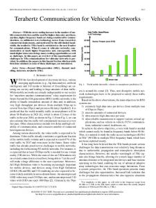
Plots in Figure 8 demonstrate the effects of applying this approach. The top plot shows the results of raising the threshold to the equivalent of QPSK (7 dB) while the lower plot is the one with threshold set to 16QAM level (12 dB).
•
Redefined the separation of functions responsibilities between PHY and MAC.
•
Introduced a new signaling interface from PHY to MAC
•
Created a PHY state machine
•
Refined the state management at MAC
•
Adjusted various parameters pertaining to DSRC
and
Lastly, a set of simulation examples is presented to demonstrate the utility of the improved simulator for vehicular communication research.
In both cases, the instances of message loss due to Reception Busy are successfully reduced. The overall effects on average broadcast reception rate at different distances, however, are different. As shown in Figure 9, raising the threshold to QPSK level provides a net benefit to DSRC safety broadcast performance while the more extreme approach turns out to be counterproductive at most distances.
7. REFERENCES 1.
The official NS-2 webpage, http://nsnam.isi.edu/nsnam/index.php/User_Information
2.
M. Takai, J. Martin, R. Bagrodia, “Effects of Wireless Physical Layer Modeling in Mobile Ad Hoc Networks”, Proc. 2001 ACM International Symposium on Mobile Ad Hoc Networking & Computing, 2001
3.
T. Elbatt, et al, “Communications Performance Evaluation of Cooperative Collision Warning Applications”, IEEE 802.11 Standardization Meeting, July 2005
4.
M. Torrent-Moreno, D. Jiang, H. Hartenstein, “Broadcast reception rates and effects of priority access in 802.11based vehicular ad-hoc networks”, Proc. 1st ACM workshop on Vehicular Ad-hoc Networks, 2004
5.
J. Yin, T. Elbatt, G. Yeung, B. Ryu, S. Habermas, H. Krishnan, T. Talty, “Performance Evaluation of Safety Applications over DSRC Vehicular Ad Hoc Networks”, Proc. 1st ACM workshop on Vehicular Ad-hoc Networks, 2004
Figure 9, Effects of Raised Reception State Entrance Threshold on Broadcast Reception Rate
6.
This discovery is very interesting and probably will be of use in DSRC based vehicular safety communication designs. But it would be the topic of another paper.
Q. Xu, T. Mak, J. Ko, R. Sengupta, “Vehicle-to-Vehicle Safety Messaging in DSRC”, Proc. 1st ACM workshop on Vehicular Ad-hoc Networks, 2004
7.
V. Taliwal, D. Jiang, H. Mangold, C. Chen, R. Sengupta, “Empirical Determination of Channel Characteristics for DSRC Vehicle-to-Vehicle Communication”, 1st ACM workshop on Vehicular ad-hoc networks, 2004
8.
M. Torrent-Moreno, P. Santi, H. Hartenstein “Fair Sharing of Bandwidth in VANETs”, Proc. 2nd ACM workshop on Vehicular Ad-hoc Networks, 2005
9.
T. Mak, K. Laberteaux, R. Sengupta, “A Multi-Channel VANET Providing Concurrent Safety and Commercial Services”, Proc. 2nd ACM workshop on Vehicular Ad-hoc Networks, 2005
Reception Probablity Comparison
Reception Probability
100% 80% 60%
BPSK QPSK 16QAM
40% 20% 0% 0
50
100
150
200
250
300
Distance From the Sender (m)
6. SUMMARY This paper presents a microscopic description of our improvements to the NS-2 simulator in its default IEEE 802.11 simulation code. The modifications are concentrated at PHY and MAC layers. The general design goal is to support more accurate modeling of wireless communications using IEEE 802.11 technologies. In particular, our aim is to ensure proper support for large-scale DSRC based vehicular communication simulation and research.
56