Towards High Speed Wireless Personal Area Network – Efficiency Analysis of MBOA MAC Yunpeng Zang, Guido R. Hiertz, Jörg Habetha, Begonya Otal, Hamza Sirin and Hans-J Reumerman
Abstract— A new generation of Wireless Personal Area Networks (WPANs) is intended for high data rate and multimedia applications. The MBOA WPAN system, which is standardized by the MultiBand OFDM Alliance (MBOA), is able to provide data rates up to 480Mb/s over a short distance based on the Ultra-Wideband (UWB) frequency band as well as support the Quality of Service (QoS) for both isochronous and asynchronous traffic. The MBOA system has been considered as one of the most potential solutions for the Physical layer (PHY) and Medium Access Control (MAC) of the next generation of WPANs. In addition to the high PHY data rates, the MBOA system provides also high MAC efficiency, especially for the high speed burst transmission and frames of small size. In this work we concentrate on the analysis of MBOA MAC layer efficiency via calculating the Theoretical Maximum Throughput (TMT). Both the numerical results and simulation results using the WARP2 simulation environment are presented for the efficiency evaluation of MBOA MAC. Index Terms—MultiBand OFDM Alliance (MBOA), Wireless Personal Area Network (WPAN), Medium Access Control (MAC), Distributed Reservation Protocol (DRP), Quality of Service (QoS), Ultra-Wideband (UWB)
NOTATIONS Notations are defined as follows and will be used throughout this paper: NFrame Number of OFDM symbols of PLCP frame payload part PSDU frame size (B) LPSDU Information bits per 6-OFDM unit NIBP6S PPDU transmission duration TPPDU TPCLPPreamble PLCP preamble duration PLCP header duration TPCLPHeader OFDM Symbol interval TSYM Imm-ACK frame duration TImm-ACK Minimum B-ACK frame duration TB-ACK LMaxMPDUSize Maximum MPDU frame body size (B) MSDU frame size (B) LMSDU Aggregation delimiter size (B) LAggDel Y. Zang is with the Chair of Communication Networks, RWTH Aachen University, 52074 Aachen, Germany (Phone: +49-241-80-25-829; fax: +49-241-80-22-242; e-mail:
[email protected]). G. R. Hiertz is with the Chair of Communication Networks, RWTH Aachen University, 52074 Aachen, Germany (e-mail:
[email protected]). J. Habetha is with Philips Research Aachen, 52066 Aachen, Germany (e-mail:
[email protected]). B. Otal is with Philips Research Aachen, 52066 Aachen, Germany (e-mail:
[email protected]). H. Sirin is with Philips Research Aachen, 52066 Aachen, Germany (e-mail:
[email protected]). H-J. Reumerman is with Philips Research Aachen, 52066 Aachen, Germany (e-mail:
[email protected]).
NAgg LPSDU,Agg SPCA NMT,MSDU NMT,PPDU T PCACycle R AC AIFS[AC] T ¯bo T TX NBurstSize NBA TBABurst TBAResidual NBAResidual SDRP TDRPcycle
⎢⎡ X ⎥⎤ ⎣⎢ X ⎦⎥
W
Number of MSDUs aggregated in one PSDU Aggregated PSDU size (B) Theoretical maximum throughput of PCA Number of MSDUs tranmitted in one TXOPLimit Number of PPDUs transmitted in one TXOPLimit Transmission time of NMT,PPDU PPDUs in one PCA TXOPLimit MBOA TMT reduce factor Access category in PCA Arbitration interframe space for access category AC in PCA Average PCA backoff time Transmission time for NMT MSDUs in one TXOPLimit Buffer size for B-ACK in unit of frame Number of complete B-ACK bursts Transmission time of one complete B-ACK burst Residual time for the incomplete B-ACK burst Number of PPDUs in TBAResidual Theoretical maximum throughput of DRP Transmission time of NMT,PPDU PPDUs in one DRP TxOPLimit Round X to the nearest integers greater than or equal to X Round X to the nearest integers less than or equal to X I. INTRODUCTION
IRELESS Personal Area Networks (WPANs) have become an ubiquitous technology. Bluetooth, as standardized by the IEEE 802.15 WPAN Working Group (WG) in 1999 [1], combines low cost and ease of use to a new class of wireless applications. Targeting at the market of broadband multimedia applications, e.g., Wireless Universal Serial Bus (WUSB) [23], [24], Wireless IEEE 1394 [19] and High Definition TV (HDTV), the next generation of WPANs is expected to provide much higher data rates as well as better Quality of Service (QoS) support. In February 2002, the Federal Communication Commission (FCC) of the United States allocated 7500MHz spectrum, from 3.1 to 10.6GHz, for unlicensed Ultra-Wideband (UWB) communication applications [25].
The IEEE 802.15 Task Group 3a (TG3a) [20], [21] was consequently formed for standardizing a high speed alternative Physical layer (PHY) based on the UWB frequency band aiming at data rates up to 480Mb/s. The MultiBand OFDM (MB-OFDM) [2] solution, as one of the two leading proposals, was proposed and supported by the MultiBand OFDM Alliance (MBOA) [3]. By noticing the drawbacks of original IEEE 802.15.3 Medium Access Control (MAC) [4] in supporting user mobility and multi-hop communication, and also due to the deadlocked down selection procedure in TG3a, MBOA standardized its own WPAN MAC [5] based on the MB-OFDM PHY outside the IEEE standardization frame. Different from the conventional centralized WPAN MACs, e.g., the Bluetooth and IEEE 802.15.3 MACs, the MBOA MAC is based a synchronized and totally distributed solution. A distributed beaconing scheme is used for time synchronization, network topology control and channel access coordination. In order to support the Quality of Service (QoS) for both isochronous and asynchronous traffics, MBOA MAC specifies the reservation based Distributed Reservation Protocol (DRP) and the contention based Prioritized Channel Access (PCA) as medium access methods [6]. MBOA MAC is efficient in high speed burst transmission, especially for frames of small size, by using Burst Acknowledgement (B-ACK) policy, Minimum Inter-Frame Space (MIFS) and frame aggregation. Other highlights of the MBOA MAC are the better support for multihop communication, comparing to the centralized solutions, and the potential abilities of spatial spectrum reuse and dynamic channel switching. Therefore, the MBOA MAC can also be considered as a candidate MAC solution for the future MESH WPAN, which is under standardizing by the IEEE 802.15 Task Group 5 (TG5) [22]. In this work we concentrate on the medium access efficiency of MBOA MAC. The paper is outlined as follows. In section II we introduce the novel MBOA PHY and MAC layers with emphases on the efforts towards higher MAC efficiency. Section III presents the quantitative analyses of MBOA MAC efficiency by calculating the Theoretical Maximum Throughput (TMT) values defined in the same section. The numerical results and simulation results of MBOA MAC performance are given and discussed in section IV and V, respectively. Section VI concludes the paper. Throughout this paper all units and abbreviations are defined according to [10]. II. MULTIBAND OFDM ALLIANCE (MBOA) WPAN
is divided into 14 bands, with each having a bandwidth of 528MHz. The 14 bands are further organized into 5 groups, of which the first four groups consist of three bands each and the last group has only two, see Fig. 1. The band hopping is carried out within each band group according to the predefined Time-Frequency Codes (TFC) and with the frequency of each hop per OFDM symbol. Totally 30 logical channels are provided by using the multiband solution and the band hopping scheme. In each 528MHz band, 100 out of 128 subcarriers are used for data transmission, 12 subcarriers for pilots and 10 for guard tones. The MB-OFDM PHY parameters can be found in Table 1.
Band Group 1
Band Group 2
Band Group 3
3432 3960 4488 5015 5544 6072 6600
Band Group 4
7128 7656 8184
Band Group 5
8712 9240 9768 10296
GHz
Fig. 1. Band group allocation of MBOA PHY on the UWB. TABLE 1 PHY PARAMETERS
Parameter Number of data subcarriers Number of pilot carriers Number of guard carriers Number of total subcarriers Subcarrier frequency spacing Symbol interval (TSYM)
Value 100 12 10 122 4.125MHz 312.5ns
Data information is modulated over each data subcarrier either by Quadrature Phase Shift Keying (QPSK) or by Dual-Carrier Modulation (DCM). The convolutional coding with a constraint length of 7 and coding rates of 1/3, 1/2, 5/8 and 3/4 is used together with the data interleaving to enhance the robustness of the data information against the wireless fading channel. In MB-OFDM PHY the inter-symbol interleaving is performed within each six-OFDM symbol block, which is also the minimum data transmission unit. Besides, frequency domain spreading and time domain spreading are employed to improve the frequency diversity and the performance of simultaneously operating piconets in MBOA system [7]. The supported data rates, modulation modes and coding rates in MB-OFDM PHY are listed in Table 2. TABLE 2 MODULATION, CODING & DATA RATES
Data Rate
Modulation
In this section we review the MBOA PHY and MAC layers with highlights on the efforts towards higher MAC (Mb/s) layer throughput. 53.3 * 80 A. Multiband OFDM PHY
*
QPSK QPSK QPSK QPSK
MB-OFDM PHY uses the well known Orthogonal 106.7 160 Frequency Division Multiplexing (OFDM) combining with band hopping technique in the UWB frequency *Mandatory data rates band. The overall 7.5GHz frequency bandwidth of UWB
Coding rate (R) 1/3 1/2 1/3 1/2
Coded bits per 6 OFDM symbols (NCBP6S) 300 300 600 600
Info bits per 6 OFDM Symbols (NIBP6S) 100 150 200 300
*
200 320 400 480
QPSK DCM DCM DCM
5/8 1/2 5/8 3/4
600 1200 1200 1200
375 600 750 900
The standard MB-OFDM Physical Layer Convergence Procedure (PLCP) frame consists of a PLCP preamble, a PLCP header and a Frame Payload, as depicted in Fig. 4. Both PHY and MAC layer headers are included in the PLCP header, which has a fixed size of 25B and is always transmitted at the data rate of 39.4Mb/s. The PLCP frame can support the payload size up to 4095B excluding the Frame Check Sequence (FCS) and Tail bits. The frame payload is transmitted using any appropriate data rate listed in Table 2. Therefore, the number of OFDM symbols needed by the PLCP Protocol Data Unit (PPDU) payload part can be calculated as:
⎡ 8 × LPSDU + FCS + Tail ⎤ N Frame = 6 × ⎢ ⎥ N IBP 6 S ⎢ ⎥
(1)
where LPSDU is the payload size in B, and NIBP6S is the number of information bits carried by per 6-OFDM symbol block, see Table 2. Values of FCS and Tail can be found in Fig. 4. Two kinds of PLCP preambles are defined in the MB-OFDM PHY, namely standard preamble and burst preamble, for the purpose of improving the burst transmission efficiency with high data rates. The burst preamble is shorter in length than the standard preamble. In a burst transmission the shortened burst preamble may be used by frames from the second on, as long as the transmission data rate is higher than 200Mb/s. The standard preamble is used by the first frame in a burst, all frames in a non-burst transmission and all frames transmitted with a data rate lower than or equals to 200Mb/s. According to the MB-OFDM PHY specification, the standard preamble consists of 30 symbols, i.e. 9.375μs long, while the burst preamble has only 18 symbols, i.e. 5.625μs. The throughput improvement yielded by using the bust preamble is discussed in section IV. B. MBOA MAC Designed for high-speed, short range communication infrastructure-less networks, the MBOA MAC differentiates itself from the traditional centralized WPAN systems, e.g., Bluetooth and IEEE 802.15.3, by using a synchronized and distributed scheme. In MBOA system, the channel time resource is organized into fix-length superframes, which comprise 256 Medium Access Slots (MASs). Each MAS lasts for 256 µs. At the beginning of each superframe a Beacon Period (BP) consisting of n 5 bytes
PLCP Preamble
PHY Header
6 bits
Tail Bits
10 bytes 2 bytes 6 bits
MAC Header
HCS
Tail Bits
PLCP Header 39.4 Mb/s
Fig. 4. MB-OFDM PLCP Frame Structure
MASs is allocated for all devices to exchange beacons, as shown in Fig. 2. It is mandatory for every device to send its beacon in the BP of each superframe. Beacons are used for maintaining the system synchronization, learning the network topology and coordinating the channel accesses [6]. Channel time other than the BP is used for data transfer, namely Data Transfer Period (DTP), which is also shown in Fig. 2.
Fig. 2. Each Superframe consists of 256 MASs. n MASs are used for the BP. The rest is used for the DTP.
To combine the efficiency of TDMA based systems with packet based technology, the MBOA system introduces the Prioritized Channel Access (PCA) and the Distributed Reservation Protocol (DRP) [8], [9]. While the first one is well known from the contention based Enhanced Distributed Channel Access (EDCA) defined in [11], the latter one is based on an advanced reservation scheme providing collision free channel access. 1) Prioritized Channel Access (PCA) The PCA is very similar to the EDCA [11] as surveyed by the authors in [12], [13], [14], [15]. It is a contention based Carrier Sense Multiple Access/Collision Avoidance (CSMA/CA) scheme relying on a prioritized backoff procedure.
Fig. 3. The PCA is based on CSMA/CA. Devices start transmitting after a random period.
6 bytes
Reed-Solomon Parity Bytes
4 bits
Tail Bits
4 bytes 6 bits
Frame Payload Variable Length: 0-4095 bytes
FCS
Tail Bits
53.3, 80, 106.7, 160, 200, 320, 400, 480 Mb/s
Pad Bits
Virtual devices of different priority inside every physical device compete for the channel access. Prior to every transmission attempt a device has to sense the channel as idle for a static period called Arbitration Interframe Space (AIFS). Afterwards, it has to keep on sensing the channel for multiples of a SlotTime. The amount of SlotTimes is a random number drawn from a uniformly distributed interval of (0, CW). The initial value of CW is CWmin. The duration of AIFS and CWmin depend on the priority of the backoff. Whenever the device senses the channel as idle it decreases its slot counter by one. If the slot counter reaches zero the device may start to transmit, as shown in Fig. 3. If the device senses the channel as busy, it freezes its slot counter. After the channel is sensed as idle for an AIFS period again, the backoff procedure resumes counting down the remaining slots. With every failed transmission a device doubles its CW to reduce the probability of a collision with other devices. Table 3 gives the priority parameters supported by MBOA PCA and Table 4 shows the MBOA PHY related parameters used by PCA.
period. The Unused DRP Announcement (UDA), Unused DRP Response (UDR) frame exchange provides unused duration of a hard reservation to other devices. For less strict demands on QoS support, DRP specifies soft reservation. In a soft reservation the PCA is used. Only the owner of the reservation can access the medium after sensing the channel idle for a AIFS period of the highest priority and without performing any backoff. The purpose of soft DRP is that, if the owner of the reservation does not fully use the reserved MASs, other devices can still share the unused MASs using PCA access. Devices can negotiate reservations either by explicitly exchanging specific command frames or by implicitly including the intended reservation information in their beacon frames. Once a DRP session has been established both the sender and the receiver have to inform their neighbors about the reservation by including the reservation information in their own beacon frames, as depicted in Fig. 5. BPST
Priority 1 2 0 3 4 5 6 7
AC AC_BK AC_BK AC_BE AC_BE AC_VI AC_VI AC_VO AC_VO
CW min 15 15 15 15 7 7 3 3
CWmax 1023 1023 1023 1023 511 511 255 255
TXOPLimit 1 frame 1 frame 1 frame 1 frame 1024µs 1024µs 256µs 256µs
7 7 4 4 2 2 1 1
TABLE 4 INTERFRAME SPACES DEFINED FOR MBOA
PHY Parameter pMIFSTime pSIFSTime pCCADetectTime pSlotTime
Value 6 * TSYM = 1.875 µs 32* TSYM = 10 µs 15* TSYM = 5.625 µs 8 µs
2) Distributed Reservation Protocol (DRP) The DRP provides a collision free channel access. It announces future transmissions and thus allows devices to coordinate their channel access, see [8], [9]. Through beaconing, devices sharing the same BP can learn the MAS occupation status and make their own reservation. The reservation is announced by the owner device in its beacon and identified with the start MAS number and the duration in unit of MASs. The MBOA MAC supports hard or soft reservations. A hard reservation enables the device owning the MASs to start its transmission immediately at the beginning of the reserved MASs, since all other devices must complete their transmissions a SIFS plus a guard interval before the reserved MAS. The reserved MAS itself may be used solely by the reserving device and its communication partners. No other transmission is permitted during that
1 2 3
Beacon Slot
Beacon Period (BP)
D A T A
A C K
SIFS AIFS
MIFS
SIFS
AIFSN
Soft DRP
Hard DRP
TABLE 3 PCA QOS PARAMETERS SUPPORTED IN MBOA MAC
D A T A
A C K
D A T A
D A T A
D A T A
MAS
D A T A
B A C K
D A T A
Backoff Slots
Data Transfer Period (DTP) Superframe
Fig. 5. The contention free DRP channel access is coordinated by information carried by the beacons.
3) Transmission Opportunities Regardless if a device accesses the channel via PCA or DRP, the duration of every frame exchange sequence is bounded by the TXOPLimit. For Transmission Opportunities (TXOPs) gained via DRP the TXOPLimit equals the duration of the reserved MASs. For PCA channel access the MBOA standard defines the TXOPLimit per priority. However, the duration of a TXOP gained under PCA is further restricted by the closest DRP reservation, since no PCA transmission may delay or foreshorten any DRP reservation. When accessing the medium with PCA or making a new DRP reservation, a device has to respect all existing reservations. Besides these limitations, all decisions regarding the data exchange are solely up to the transmitting device. 4) Acknowledgement policies & Minimum Interframe Space MBOA defines three Acknowledgment (ACK) policies: • No-ACK • Immediate ACK • Burst ACK. Each directed frame carries an “ACK policy” field in the frame control field inside the MAC header, to allow the receiver to use the desired one. With No-ACK policy no ACKs are generated at all. As shown in Fig. 6. (a), with Immediate ACK (Imm-ACK) policy each successfully received Mac Protocol Data Unit (MPDU) is acknowledged after a Short Interframe Space (SIFS) period
by the receiver. The SIFS period is needed for transceiver (TRX) turnaround and frame checking. It is used in between every frame exchange. With Burst ACK (B-ACK), a burst of frames up to the burst ACK buffer size can be transmitted before the receiver is requested for a burst ACK frame, see Fig. 6. (b). According to the information contained in the burst ACK frame from the receiver, the transmitter can retransmit the missed frames or go on with the new ones as long as the burst ACK buffer size is not exceeded. TXOPLimit SIFS DA TA
DA TA A C K
DA TA A C K
DA TA A C K
DA TA A C K
A C K
SIFS
SIFS (a)
timer is set according to the oldest MSDU in the aggregated frame. The aggregated frame is processed as a single indivisible entity, in term of acknowledgement and retransmission. As we will show in IV, frame aggregation can significantly bring up the MAC efficiency for frames of small size. 6) Other MAC functions Other MAC functions of MBOA system like beaconing scheme, transmission power control and distance measurements are also specified in MBOA MAC, which are presented by the authors with more details in [6]. 10 Octets
L
0 or 4
MAC Header
Frame Payload
FCS
Aggregation Header
2+(2xN) Octets
Pad
MSDU1
Pad to 4-octet boundary
...
Pad
MSDU N
Pad to 4-octet boundary
Fig. 7. An aggregated frame consists of multiple independent MSDUs. The aggregation header indicates the length of each MSDU.
TXOPLimit MIFS
SIFS
MIFS
SIFS
III. THEORETICAL MAXIMUM THROUGHPUT (TMT) FOR MBOA MAC DA TA
DA TA
DA TA
DA TA
DA TA B A C K
DA TA
DA TA
DA TA B A C K
SIFS
SIFS
(b) Fig. 6. (a) Imm-ACK requires a ACK frame for each data frame after a SIFS interval; (b) Burst ACK demands a burst ACK frame for a burst transmission.
When No-ACK or Burst ACK policies are used, numbers of frames can be transmitted in a row, namely burst, without turning around the transmission direction. The Minimum Interframe Space (MIFS), which is shorter than the SIFS interval due to the absence of transceiver turnaround time, is used in between the consecutive burst frames, see Fig. 6 (b). The value of MIFS and SIFS are given in Table 4 and the throughput improvements achieved by using No-ACK and Burst ACK policies are further discussed in section III and [18]. 5) Frame aggregation In MBOA system, every device may benefit from frame aggregation. Frame aggregation concatenates subsequent frames into a single MAC Protocol Data Unit (MPDU) payload. However, the aggregated frame is subject to the same maximum size as any data frame payload. The aggregated frame structure is illustrated in Fig. 7, where the processed MAC Service Data Units (MSDUs) are padded to 4 octet boundary and attached with a common header holding the length information of each MSDU and the number of aggregated MSDUs. To prevent the excessive delay for the MSDUs, a release
In order to analyze the MBOA MAC efficiency, we evaluate the Theoretical Maximum Throughput (TMT) introduced by [26]. The throughput value is evaluated at the Service Access Point (SAP) of MAC sublayer in the absent of transmission errors, i.e., with an ideal channel model. TMT describes the maximum capacity that the MAC layer, based on certain PHY modes, can provide to upper layers taking account of all the overhead introduced by PLCP and MAC sublayers. TMT is calculated by dividing the amount of information bits exchanged between the peer MAC entities by the duration needed for successfully delivering them:
S=
AmountOfInformationBits TransmissionDuration
(2)
Similar study for the IEEE 802.11 system can be found in [26], [27]. It has to be noticed that TMT does not give an accurate idea of the saturation throughput of the MAC layer, especially in the case of multiple users contending for a single channel, but only a theoretical upper boundary, which is limited by the overhead introduced by the protocol itself. In this work, we evaluate the efficiency of different MAC strategies by calculating TMT values. More accurate saturation throughput analysis model for the MBOA system is currently under developing by the authors, while the similar work for IEEE 802.11 EDCA can be found in [28], [29], [30]. A. PLCP Protocol Data Unit (PPDU) transmission time Before evaluating the TMT value for both PCA and DRP, we first give out several elements that will be used in the analysis.
1) MBOA PPDU frame transmission time As shown in Fig. 4, for a given PHY mode, the duration of transmitting a PPDU is calculated as TPPDU = TPLCPPreamble + TPLCPHeader + TSYM ⋅ N Frame (3) where TPLCPPreamble is the duration of the PLCP preamble, which can be either standard or burst PLCP preamble, TPLCPHeader is the duration of the PLCP header and NFrame is the number of OFDM symbols occupied by the PPDU payload part, which is given by (1). 2) MBOA ACK frame transmission time According to the MBOA MAC specification, the Imm-ACK frame consists of null payload and only a MAC header. Therefore the transmission time of an Imm-ACK frame is TImm − ACK = TPLCPPreamble + TPLCPHeader (4) The B-ACK frame consists of a MAC header and a payload part, as shown in Fig. 8. Octets: 2
1
1
2
0-n
Buffer Size
Frame Count
Reserved
Sequence Control
Frame bitmap
The last field in the frame payload part is used by the acknowledgement bitmap, whose length varies according to the size of the acknowledgement window. In case ideal channel model is used, there is no transmission error occurring, thus no bitmap is needed for indicating a retransmission. The minimum B-ACK frame size can be used for surveying the TMT with B-ACK policy:
⎡ 8 ⋅ ( 6 + FCS ) + Tail ⎤ TB − ACK = TPLCPPreamble + TPLCPHeader + 6 × TSYM ⋅ ⎢ ⎥ N IBP 6 S ⎢ ⎥
(5) 3) MBOA aggregation frame transmission time The aggregated frame body structure is shown in Fig. 7. Assuming all MSDUs are of the same size, the maximum number of MSDUs that can be aggregated into one MPDU frame body is calculated as ⎢ ⎥ ⎢ ⎥ (6) ⎢ LMaxMPDUSize − 2 ⎥ N Agg = ⎢ ⎡ LMSDU ⎤ ⎥ ⎢2 + L ⎥⎥ AggDel × ⎢ ⎢ L ⎢ AggDel ⎥ ⎥⎦ ⎣ where LMaxMPDUSize = 4095B is the maximum frame body size for MBOA MPDU. LMSDU is the frame size of MSDUs being aggregated and LAggDel = 4B is the aggregation delimiter. Therefore, the aggregated PLCP Service Data Unit (PSDU) size can be calculated by
(7)
B. TMT of PCA According to the definition, the TMT of PCA mode is presented as: 8 ⋅ N MT , MSDU ⋅ LMSDU (8) S = ⋅ R (b / s ) PCA
R=
DataTranmissionPeriodLength SuperframeLength
(9)
As depicted in II.B.1), TPCACycle of PCA consists of the average time required for getting access to the media and the time actually used for finishing the MSDU transmission sequence: (10) TPCAcycle = AIFS [ AC ] + T bo ( 0, AC ) + TTX where the value of AIFS[AC] is given by AIFS [ AC ] = aSIFSTime + AIFSN [ AC ] ⋅ aSlotTime (11) The average backoff interval after i consecutive unsuccessful transmission attempts can be calculated by ⎧ 2i ( CWmin ( AC ) + 1) − 1 ⎪⎪ T bo (i, AC ) = ⎨ ⎪ ⎪⎩
⋅ aSlotTime 0 ≤ i ≤ N CWincrease 2 CWmax ( AC ) ⋅ aSlotTime i > NCWincrease 2
(12)
Fig. 8. Burst ACK MAC frame body structure
⎛ ⎡L ⎤⎞ LPSDU , Agg = 2 + N Agg ⎜ 2 + LAggDel × ⎢ MSDU ⎥ ⎟ ⎜ ⎢ LAggDel ⎥ ⎟⎠ ⎝
the actual time required to successfully deliver those MSDUs. R is the reduce factor introduced by the MBOA MAC superframe structure as described in II.B:
TPCAcycle
where NMT,MSDU is the total number of MSDUs that can be completed in one TXOPLimit and TPCACycle denotes
where NCWincrease can be derived from: ⎛ CWmax ( AC ) + 1 ⎞ N CWincrease = log 2 ⎜ ⎟ ⎝ CWmin ( AC ) + 1 ⎠
(13)
All AC related QoS parameters are listed in Table 3. Both NMT,MSDU in (8) and TTX in (10) are functions of the TXOPLimit value, PHY mode r and MSDU size LMSDU. They also depend on the aggregation policy and acknowledgement policy used for the transmission. For each acknowledgement policy, the calculations of NMT,MSDU and TTX are presented as follows. 1) PCA with No-ACK With the acknowledgement policy of No-ACK, the maximum number of PPDUs that fit into one TXOPLimit is calculated by ⎢ TTXOPLimt − aSIFSTime + aMIFSTime ⎥ (14) N MT , PPDU = ⎢ ⎣
r TPPDU + aMIFSTime
⎥ ⎦
As for any transmission a SIFS time at end of each TXOP should be always reserved, a aSIFSTime in the numerator is subtracted from the TXOPLimit. From (14), we can see the MIFS instead of SIFS is used in between consecutive frames. The actual transmission time of the burst is
TTX = ( N MT , PPDU − 1) ⋅ (TPPDU + aMIFSTime ) + TPPDU + aSIFSTime
(15) 2) PCA with Imm-ACK As depicted in Fig. 6 (a), the maximum number of PPDUs that can be finished in one TXOPLimit using Imm-ACK is calculated as ⎢ ⎥ (16) TTXOPLimit N MT , PPDU = ⎢ ⎥ ⎣ TPPDU + TImm − ACK + 2 × aSIFSTime ⎦
The actual transmission time of the NMT,PPDU PPDU sequence is TTX = N MT , PPDU ⋅ (TPPDU + TImm − ACK + 2 × aSIFSTime ) − aSIFSTime
(17) 3) PCA with B-ACK The B-ACK exchange process is illustrated in Fig. 6 (b). To find out the total number of PPDUs finished in one TXOP using B-ACK, we first survey the number of complete B-ACK bursts occurring in the TXOPLimit and
then the number of PPDUs delivered in the last incomplete burst, if there is still enough time. Here, we assume that all frames transmitted in one TXOPLimit should be acknowledged in the same TXOP. The number of complete B-ACK bursts is ⎥ ⎢T (18) N BA = ⎢ TXOPLimt ⎥ ⎣ TBABurst ⎦ where TBABurst denotes the time duration of one complete B-ACK exchange sequence, which is composed of NBurstSize PPDUs, a B-ACK frame and corresponding interframe spaces: TBABurst = N BurstSize ⋅ (TPPDU + aMIFSTime )
(19)
−aMIFSTime + TB − ACK + 2 × aSIFSTime
We use TBAResidual to denote the time remaining in the TXOPLimit for an incomplete B-ACK burst and its value is given by: TBAResidual = TTXOPLimit − N BA × TBABurst (20) The maximum number of PPDUs can be finished in the last incomplete burst is ⎢T −T − 2 × aSIFSTime + aMIFSTime ⎥ N BAResidual = ⎢ BAResidual B − ACKr ⎥ T PPDU + aMIFSTime ⎣ ⎦
(21) Therefore, the total number of PPDUs that can be transmitted and acknowledged within a TxOPLimit is calculated as (22) N MT , PPDU = N BA ⋅ N BurstSize + N BAResidual If NBAResidual is greater than 0, the actual transmission time used by NMT,PPDU PPDU frames in the TxOPLimit is given by: TTX = N BA ⋅ TBABurst + N BAResidual ⋅ (TPPDU + aMIFSTime ) (23)
Therefore, the TDRPcycle equals the reservation duration, i.e., TTXOPLimit.
TDRPcycle = TTXOPLimit
While in soft reservation mode, as explained in II.B.2), a channel idle duration of AIFSSoftRes has to be sensed before the owner of the reservation can start the transmission. Hence, TDRPcycle of soft reservation can be expressed as:
TDRPcycle = AIFS SoftRes + TTX
IV. NUMERICAL RESULTS In this section, we present the numerical results for MBOA TMT as analyzed in section III. Maximum Throughput of MBOA Hard−DRP (PHY mode: 480Mb/s)
The burst PLCP preamble applies to the burst transmission, i.e., the cases with No-ACK or B-ACK policy, as explained in II.A. As a result, the throughput performance of burst transmission is improved, as we will show in section IV. Furthermore, frame aggregation, as described in II.B.5), can be used together with any of the three acknowledgement policies. For the case without frame aggregation, the NMT,MSDU in (8) is exactly the number of PPDUs: (25) N MT , MSDU = N MT , PPDU while if frame aggregation is used, then:
N MT , MSDU = N MT , PPDU ⋅ N agg
(26)
where Nagg is given by (6). C. TMT of DRP Following the same approach as for PCA, the TMT formula for DRP can be expressed as: 8 ⋅ N MT , MSDU ⋅ LMSDU (27) S = ⋅ R (b / s ) DRP
TDRPcycle
The value of TDRPcycle depends on which DRP mode is employed, hard reservation or soft reservation. Hard reservation time is used in a strict TDMA way.
Throughput (Mb/s)
(24)
(29)
where AIFSSoftRes is fixed to the value given by (11) corresponding to the AC of the highest priority in PCA and TTX is calculated in the same way as for PCA. For each acknowledgement policy the TTX value of soft reservation is given by (15), (17) and (23) or (24), respectively. In both hard and soft reservation modes, the calculation of NMT,MSDU for each acknowledgement policy is exactly the same as in PCA mode. When calculating TTX for the soft DRP and NMT,MSDU for both hard and soft DRP, TTXOPLimit in (14), (16), (18) and (20) stands for the reservation duration made by DRP instead of the TXOP length defined by PCA QoS parameters. Besides, the burst PLCP preamble and frame aggregation apply as well to DRP modes as analyzed in PCA mode.
+TB − ACK − aMIFSTime + aSIFSTime Otherwise,
TTX = N BA ⋅ TBABurst − aSIFSTime
(28)
400 380 360 340 320 300 280 260 240 220 200 180 160 140 120 100 80 60 40 20 0
Burst Preamble, MIFS Std. Preamble, MIFS Std. Preamble, SIFS 500
1000
1500
2000
2500
3000
3500
4095
Packet Size (B)
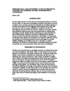
Fig. 9. Maximum throughput of MBOA Hard-DRP mode using Burst-ACK (burst size=16).
MBOA can improve the throughput of burst transmission by using MIFS, as described in II.B.4). Fig. 9 shows that about 40Mb/s gain is yielded by using MIFS in between of consecutive PPDUs instead of SIFS, when each burst consists 16 PPDUs. Further improvement of 20Mb/s can be achieved by using the shortened burst preamble instead of standard preamble, as introduced in II.A. TMT of MBOA hard DRP and PCA with respect to the frame size are shown in Fig. 10 and Fig. 11 for PHY modes 480Mb/s and 200Mb/s, respectively. In these calculations, we assume the beacon period length is fixed
TMT of MBOA DRP and PCA (PHY mode: 480Mb/s) 400 380 360 340 320
mode. That is why the TMT values of big frames and all aggregated frames drop to zero in PCA mode. TMT of MBOA DRP and PCA (PHY mode: 53Mb/s) 55 50 45
Throughput (Mb/s)
to 8 MASs and reservation duration for hard and soft reservation both take the maximum DTP length, i.e., 248 MASs. MIFS and burst preamble are used as long as they are applicable. And the values for PCA mode are calculated with the AC of the highest priority, i.e., AC_VO. Here we show only the TMT results for hard DRP and PCA, as the TMT value for soft DRP are quite close to the ones for hard DRP.
40 35 30 25 Hard−DRP,No−ACK Hard−DRP,B−ACK Hard−DRP,Imm−ACK PCA,No−ACK PCA,B−ACK PCA,Imm−ACK Hard−DRP,No−ACK,Agg Hard−DRP,B−ACK,Agg Hard−DRP,Imm−ACK,Agg PCA,No−ACK,Agg PCA,B−ACK,Agg PCA,Imm−ACK,Agg
20
300 15
Throughput (Mb/s)
280 260
10
240 5
220 200
0
180 Hard−DRP,No−ACK Hard−DRP,B−ACK Hard−DRP,Imm−ACK PCA,No−ACK PCA,B−ACK PCA,Imm−ACK Hard−DRP,No−ACK,Agg Hard−DRP,B−ACK,Agg Hard−DRP,Imm−ACK,Agg PCA,No−ACK,Agg PCA,B−ACK,Agg PCA,Imm−ACK,Agg
140 120 100 80 60 40 20 0
1500
2000
2500
3000
3500
4095
500
1000
1500
2000
2500
3000
3500
V. SIMULATIVE ANALYSIS 4095
Fig. 10. TMT for MBOA MAC with PHY mode of 480Mb/s TMT of MBOA DRP and PCA (PHY mode: 200Mb/s) 180 170 160 150 140 130
Throughput (Mb/s)
1000
Fig. 12. TMT for MBOA MAC with PHY mode of 53Mb/s
Packet Size (B)
120 110 100 90 80 70
Hard−DRP,No−ACK Hard−DRP,B−ACK Hard−DRP,Imm−ACK PCA,No−ACK PCA,B−ACK PCA,Imm−ACK Hard−DRP,No−ACK,Agg Hard−DRP,B−ACK,Agg Hard−DRP,Imm−ACK,Agg PCA,No−ACK,Agg PCA,B−ACK,Agg PCA,Imm−ACK,Agg
60 50 40 30 20 10 0
500
Packet Size (B)
160
500
1000
1500
2000
2500
3000
3500
4095
Packet Size (B)
Fig. 11. TMT for MBOA MAC with PHY mode of 200Mb/s
The calculation results show that TMT values of DRP always outperform the ones of PCA with the same acknowledgement policy. The reason is, on one hand, PCA introduces the overhead of AIFS and backoff, and on the other hand, the too short TXOPLimit (256μs for AC_VO) further increases the proportion of the overhead. As expected, in both DRP and PCA modes, the maximum TMT is achieved by No-ACK policy, which is followed by the B-ACK policy with a slight lower value due to the overhead of B-ACK frames. It is clear that the throughputs for frames of small sizes are brought up significantly by using frame aggregation. It has to be noticed that with a low PHY mode, e.g. 53.3Mb/s, as shown in Fig. 12, frames of large size and aggregated frames can not even be send because of the small TXOPLimit value of AC_VO, i.e., 256μs, in PCA
We also use event-driven stochastic simulations to analyze the efficiency of the MBOA MAC layer. Simulation campaigns have been performed based on the MB-OFDM PHY, as introduced in II.A. The simulations were performed using the Wireless Access Radio Protocol 2 (WARP2) simulation environment developed at the Chair of Communication Networks, RWTH Aachen University [16]. It is programmed in the Specification and Description Language (SDL) using Telelogic’s TAU SDL Suite (previously named SDL Design Tool (SDT)). The error model used in WARP2 to accurately simulate the Wireless Medium (WM) is presented in [17]. In order to evaluate the efficiency of the MBOA MAC layer, all simulations presented here use an ideal channel. All devices are within reception range of each other, thus on hidden devices appear in our simulations. To survey the maximum achievable throughput of MBOA, we set up the same scenarios as described for TMT calculations. Fig. 13 shows that the maximum throughputs of hard and soft DRP are almost the same when the reservation duration is large. Without transmission error, the maximum throughput of 398Mb/s can be reached by using No-ACK policy and DRP. Comparing the simulation results in Fig. 13 and Fig. 14 with the analytical calculation results in Fig. 10, we can see they match each other very well. This also verified our analyses.
Throughput of Mixed Hard−DRP and PCA routes (PHY mode: 480Mb/s)
Maximum Throughput of MBOA DRP (Hard & Soft) (PHY mode: 480Mb/s) 400
180
380
170
360
160
340
150
320
140
300
130
Overall System Throughput
120
260
Throughput (Mb/s)
Throughput (Mb/s)
280
240 220 200 180 160 DRP No−ACK DRP B−ACK DRP Imm−ACK Soft−DRP No−ACK Soft−DRP B−ACK Soft−DRP Imm−ACK DRP No−ACK with Agg. DRP B−ACK with Agg. DRP Imm−ACK with Agg. Soft−DRP No−ACK with Agg. Soft−DRP B−ACK with Agg. Soft−DRP Imm−ACK with Agg.
140 120 100 80 60 40 20 0
500
1000
1500
2000
2500
3000
3500
110 100 90 80 70 60 50 40 30 Hard−DRP Imm−ACK Hard−DRP Imm−ACK PCA Imm−ACK PCA Imm−ACK System Throughput
20 10 0
4095
10
20
Fig. 13. Simulation results for the maximum throughput of MBOA hard and soft DRPs
50
60
70
80
Throughput of Mixed Soft−DRP and PCA routes (PHY mode: 480Mb/s) 180
340
170
320
160
300
150
280
Overall System Throughput
140
260
130
240
120
Throughput (Mb/s)
Throughput (Mb/s)
40
Fig. 15. Throughput evaluation of the mixed scenario with 2 hard DRP routes and two overloaded PCA routes.
Maximum Throughput of MBOA PCA (PHY mode: 480Mb/s)
220 200 180 160 140
110 100 90 80 70
120
60
100
50
80
40
PCA No−ACK PCA B−ACK PCA Imm−ACK PCA No−ACK with Agg. PCA B−ACK with Agg. PCA Imm−ACK with Agg.
60 40 20 0
30
Traffic Load of DRP routes (Mb/s)
Packet Size (B)
500
1000
1500
2000
2500
3000
3500
30 Soft−DRP Imm−ACK Soft−DRP Imm−ACK PCA Imm−ACK PCA Imm−ACK System Throughput
20 10
4095
Packet Size (B)
Fig. 14. Simulation results for the maximum throughput of MBOA PCA
As described in II.B.2), soft DRP can provide better system throughput when it is used together with PCA and more flexible QoS support compared with hard DRP. In order to investigate the performance of soft DRP, we set up two scenarios. In the first scenario, two DRP routes reserve half of the channel time resource through hard reservation and the rest channel time is shared by other two overloaded PCA routes. All routes use frame sizes of 1500B and Imm-ACK. Both PCA routes are of AC_VO. The second scenario takes the same configuration as the first one except that the DRP routes make soft reservation instead of hard reservation. To evaluate the system throughput, we keep increasing the traffic loads for the DRP routes, while the PCA routes are always overloaded. The throughput results are shown in Fig. 15 and Fig. 16 for the first and the second scenarios, respectively. It is clear that soft reservation provide better overall system throughput when the DRP routes are underloaded. The reason is that the unused soft reservation time can be shared by PCA routes, while the unused hard reservation time is still inaccessible for other routes unless the UDR and UDA frames are exchanged.
0
10
20
30
40
50
60
70
80
Traffic Load of DRP Routes (Mb/s)
Fig. 16. Throughput evaluation of the mixed scenario with 2 soft DRP routes and two overloaded PCA routes.
VI. CONCLUSIONS In this paper we have presented and analyzed the new MBOA MAC protocol. Our TMT analyses of MBOA MAC layer have shown the improvement on the MAC efficiency achieved by using burst PLCP preamble, Burst ACK, MIFS and frame aggregation, which are specified in the MBOA MAC and PHY. We also implemented the MAC protocol in our event driven simulator WARP2 and provide the performance evaluation of both DRP and PCA access methods. Simulation results indicate that the protocol is very efficient and that concerning the system throughput the soft DRP is more efficient and flexible than the hard DRP without URD/URA. ACKNOWLEDGMENT The authors would like to thank Prof. Dr.-Ing. B. Walke for his friendly advice to this work and Francesc Falmases, Javier del Prado Pavon, Kiran Challapali and Sai Shankar for the fruitful collaboration. The contributions of our colleague Sebastian Max are highly appreciated.
REFERENCES [1]
[2] [3] [4]
[5] [6]
[7]
[8]
[9]
[10]
[11]
[12] [13]
[14]
[15]
[16] [17]
[18]
IEEE Standard for Information technology – Telecommunications and information exchange between systems – Local and metropolitan area networks – Specific requirements, Part 15.1: Wireless Medium Access Control (MAC) and Physical Layer (PHY) Specifications for Wireless Personal Area Networks (WPANs), IEEE 802.15.1, Jun. 2002 MBOA – PHY Layer Technical Specification, MBOA PHY Specification Final Draft 1.0, Jan. 14, 2005 MultiBand OFDM Alliance. [Online]. Available: http://www.multibandofdm.org/ Draft Standard for Telecommunications and Information Exchange Between Systems – LAN/MAN Specific Requirements – Part 15.3: Wireless Medium Access Control (MAC) and Physical Layer (PHY) Specifications for High Rate Wireless Personal Area Networks (WPAN), IEEE Draft Standard 802.15.3/16, Feb. 2003 MBOA – Wireless Medium Access Control (MAC) Specification for High Rate Wireless Personal Area Networks (WPANs), MBOA MAC Specification Draft 0.93, Jan. 28, 2005 G. R. Hiertz, Y. Zang, J. Habetha and H. Sirin, „Multiband OFDM Alliance – The next generation of Wireless Personal Area Networks”, Proceedings of the IEEE Sarnoff Symposium 2005, Princeton, New Jersey, U.S., Apr. 2005 A. Batra, J. Balakrishnan, G. R. Aiello, J. R. Foerster and A. Dabak, „Design of a multiband OFDM system for realistic UWB channel environments”, Microwave Theory and Techniques, IEEE Transactions on Volume 52, Issue 9, Sept. 2004 Page(s):2123 - 2138 G. R. Hiertz and J. Habetha, „A new MAC Protocol for a wireless multi-hop broadband system beyond IEEE 802.11”, Wireless World Research Forum, 9th Meeting in Zurich, Switzerland, Jul. 2003 G. R. Hiertz, J. Habetha, P. May, E. Weiß, B. Rajesh and S. Mangold, „A Decentralized Reservation Scheme for IEEE 802.11 Ad Hoc Networks”, The 14th IEEE 2003 International Symposium on Personal, Indoor and Mobile Radio Communications, ISBN 0-7803-7823-7, Beijing, China, Sep. 2003 IEEE Transactions, Journals and Letters – Information for Authors, IEEE Periodicals Transactions/Journals Department, auinfo03.pdf, IEEE, 445 Hoes Lane, P.O. Box 1331, Piscataway, NJ 08855-1331, USA, [Online]. Available: http://www.ieee.org/portal/cms_docs/pubs/transactions/auinfo03. pdf IEEE Standard for Information technology – Telecommunication and information exchange between systems – Local and metropolitan area networks – Specific requirements, Part 11: Wireless Medium Access Control (MAC) and Physical Layer (PHY) specifications: Amendment 7: Medium Access Control (MAC) Quality of Service (QoS) Enhancements, IEEE Draft Amendment P802.11e/D11.0, Oct. 2004 S. Mangold, S. Choi, G. R. Hiertz, O. Klein, B. Walke, “Analysis of IEEE 802.11 for QoS Support in Wireless LANs”, IEEE Wireless Communications, Vol. 10, Dec. 2003, p.p. 2-12 S. Mangold, G. R. Hiertz, B. Walke, “IEEE 802.11e Wireless LAN - Resource Sharing with Contention Based Medium Access”, Proceedings of the PIMRC 2003, Bejing, P.R. China, Sep. 2003 S. Mangold, S. Choi, P. May, P., G. R. Hiertz, “IEEE 802.11e Fair Resource Sharing between Overlapping Basic Service Sets”, In Proceedings of the PIMRC 2002, p.p. 166-171, Lisbon, Portugal, Sep. 2002 S. Mangold, S. Choi, S. P. May, O. Klein, Ole, G. R. Hiertz, L. Stibor, “IEEE 802.11e Wireless LAN for Quality of Service”, Proceedings of the European Wireless, Vol. 1, p.p. 32-39, Florence, Italy, Feb. 2002 Chair of Communication Networks, RWTH Aachen University, Kopernikusstraße 16, 52074 Aachen, Federal Republic of Germany, [Online]. Available: http://www.comnets.rwth-aachen.de S. Mangold, S. Choi, N. Esseling, “An error model for radio transmissions of wireless LANs at 5GHz”, Proceeding Aachen Symposium 2001, Aachen, Federal Republic of Germany, Sept. 2001 G. R. Hiertz, L. Stibor, J. Habetha, E. Weiß, S. Mangold, “Throughput and Delay Performance of IEEE 802.11e Wireless LAN with Block Acknowledgements”, European Wireless 2005, Nicosia, Cyprus, Apr. 2005
[19] Standard for High Performance Serial Bus, IEEE Standard 1394-1995, Aug. 1996 [20] IEEE P802.15 Working Group for Wireless Personal Area Networks (WPANs), “SG3a Five Criteria”, P802.15-02/371r0, Aug. 2002 [21] Project Authorization Request for “Draft: Amendment to Standard for Telecommunications and Information Exchange Between Systems - LAN/MAN – Specific Requirements - Part 15.3: Wireless Medium Access Control (MAC) and Physical Layer (PHY) – Specifications: Higher Speed Physical Layer Extension for the High Rate Wireless Personal Area Networks (WPAN)”, IEEE P802.15.3a, May 2004 [22] IEEE P802.15 Working Group for Wireless Personal Area Networks (WPANs), “SG5 Project Authorization Request and Five Criteria”, P802.15-04/042r0, Jan. 2004 [23] Universal Bus Specification, Revision 2.0, Compaq, Hewlett-Packard, Intel, Lucent, Microsoft, NEC, Philips, Apr. 2000. [Online]. Available: http://www.intel.com/technology/usb/spec.htm [24] The Wireless USB Promoter Group. [Online]. Available: http://www.usb.org/wusb [25] Federal Communications Commission, “New public safety applications and broadband internet access among uses envisioned by FCC authorization of ultra-wideband technology”, Feb. 2002. [Online]. Available: http://www.fcc.gov/Bureaus/Engineering_Technology/News_Rel eases/2002/nret0203.html [26] J. Jun, P. Peddabachagari and M. Sichitiu, “Theoretical maximum throughput of IEEE 802.11 and its applications”, Network Computing and Applications, 2003. NCA 2003. Second IEEE International Symposium on 16-18 April 2003 Page(s):249 – 256 [27] Y. Xiao and J. Rosdahl, “Throughput and delay limits of IEEE 802.1”,1Communications Letters, IEEE Volume 6, Issue 8, Aug. 2002 Page(s):355 – 357 [28] G. Bianchi, “Performance analysis of the IEEE 802.11 distributed coordination function”, Selected Areas in Communications, IEEE Journal on Volume 18, Issue 3, March 2000 Page(s):535 – 547 [29] J. W. Robinson and T. S. Randhawa, “Saturation throughput analysis of IEEE 802.11e enhanced distributed coordination function”, Selected Areas in Communications, IEEE Journal on Volume 22, Issue 5, June 2004 Page(s):917 – 928 [30] Z. Hadzi-Velkov and B. Spasenovski, “Saturation throughput delay analysis of IEEE 802.11 DCF in fading channel”, Communications, 2003. ICC '03. IEEE International Conference on Volume 1, 11-15 May 2003 Page(s):121 - 126 vol.1