GSM Calling based Multi-tasking Robot vehicle with ..... the robot. So, a project called 'Alarm Phone Dialer' can be built which will generate necessary alarms for ...
Volume 4, Issue 1, January 2014
ISSN: 2277 128X
International Journal of Advanced Research in Computer Science and Software Engineering Research Paper Available online at: www.ijarcsse.com
GSM Calling based Multi-tasking Robot vehicle with Password protection Amritanshu Srivastava1, Hrishikesh Narayan Tripathi2 School of Electronics and Communication engineering, Shri Mata Vaishno Devi University, Jammu, India Abstract— The objective of designing this robot is simply to facilitate the humans in the future for security purposes. In the present scenario, there are many recent developments of robotics and communication on a large scale. In this paper we are using both the technologies. The methodology used in this paper is DTMF (Dual Tone MultiFrequency). Our robot is controlled by a cell phone, through this we can make our robot communicate on a large scale over a large distance even from different cities. This robot has a number of advantages as well as important features such as password protection, automatic avoiding obstacles in its way, automatic edge detection so that robot can protect itself from falling from heights. It can sense humidity, temperature, smoke and metallic bombs and hence immediately provide an alert through text messaging to the calling person. The temperature and humidity of the place is displayed on a LCD display. This robot can also be used to reach the places where humans cannot reach such as small tunnels, etc. This is how we can use this robot in different fields as well as for research purpose by further manipulation in programming it can be modified accordingly. Keywords— DTMF (dual tone multiple frequency); Sensors; Robotic car; GSM module; Microcontroller 89S52 I. INTRODUCTION “ROBOT” is any automatically operated machine that replaces human effort, though it may not look much like a human being or function in a humanlike manner. Advanced, high-performance robots are used today in automobile manufacturing and aircraft assembly, and electronics firms use robotic devices together with other computerized instruments to sort or test finished products. Due to this demand of intelligent systems in every field of technology, automated systems are preferred much for the betterment of the society. Wireless Communication is the most evolving fields of application in present scenario, where different technologies can be used so as to have automated systems with flexibility, reliability and accuracy. Conventionally, wirelesscontrolled robots use RF circuits, which have the drawbacks of limited working range, limited frequency range and limited control. Use of a mobile phone for robotic control can overcome these limitations. It provides the advantages of robust control, working range as large as the coverage area of the service provider, no interference with other controllers and up to twelve controls. So This system will be a powerful and flexible tool that will offer this service at any time, and from anywhere with the constraints of the technologies being applied. Possible target appliances include (but are not limited to) climate control systems, security systems, and home appliances and anything with an electrical interface. Sng Hong Lian developed an obstacle avoidance mobile robot [1] which is controlled by a Fuzzy logic controller which can also measure the distance and climb up the walls in which the Fuzzy logic concept was adopted. Dong-ying Ju worked on the development of Remote control and Monitors system [4] by using GPRS networking concept. Karthi Balasubramanium worked on developing a robot for object recognition and obstacle avoidance [3] using the concepts of image processing and SONAR technology. Yen-Sheng chen developed the wheeled mobile robot [2] that utilizes signals of the ultrasonic sensors to avoid obstacle and fuzzy theory with sensor signals is used to control the speed of the wheeled mobile robot and make it move to target location. In this manuscript, I am controlling a robot vehicle through wireless communication system using DTMF technology. Microcontroller 89S52 is used to control all operations. As the call is made to the robot the robot will ask a password from the user and proceed when only correct password is entered. According to the button pressed on the transmitting cell phone, the robot will move. But if any obstacle is sensed by the robot, it will change its direction or it will stop and if robot senses an edge, it will immediately change its direction to protect itself from falling. This is also an intelligent system which includes gas sensor, smoke sensor and metal sensor for the security purposes in homes. The main aim of using these sensors is to monitor smoke, gas leakage in houses as well as industries. If the voltage level of these sensors exceeds the threshold voltage, an alert to the caller is given through a text message. II. OVERVIEW OF THE TECHNOLOGY USED DTMF stands for dual tone multiple frequency. DTMF is a term which used in telephone industry. DTMF generation is a composite audio signals of two tones between the frequency of 697Hz and 1633Hz. The DTMF keypad is arranged such that each row will have its own unique tone frequency and also each column will have its own unique tone. Below © 2014, IJARCSSE All Rights Reserved
Page | 812
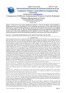
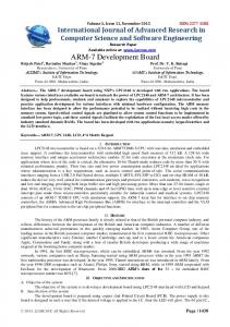
Srivastava et al., International Journal of Advanced Research in Computer Science and Software Engineering 4(1), January - 2014, pp. 812-819 is a representation of the typical DTMF keypad and the associated row/column frequencies. When any of the key like "1", "2", "*", "#" etc is pressed particular code is transmitted. This code is consist of two frequency among which one is higher frequency and second one is lower frequency(see Fig 2).
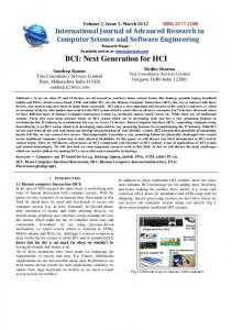
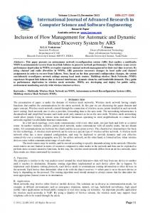
Fig. 1 The combination of frequency for respected keys. When any DTMF code has been received at mobile phone it can be audible through speaker. So to decode this DTMF code speaker output itself can be used. Output of speaker is connected to IC MT8870 which is DTMF decoder IC. It used widely to decode DTMF code. It gives 4-bit digital output q1, q2, q3, and q4 according to the received key(see Fig. 2). Following figure shows the equivalent digital output for each key.
Fig. 1 The equivalent digital output for each key. Our main aim is to connect mobile phone's speaker output to MT8870 so for achieving this we will useaux cable which has 3.5mm male audio jack (see Fig 3) at both its end as shown in below image. 3.5mm audio jack is a TRS connector which is Tip Ring Sleeve (ground) as shown in below image. Just connect your cell phone headset (headphone) jack to the mobile phone and then mobile control electrical appliances and electrical equipment via DTMF key pad of your cell phone. Go through following images to get clear understanding.
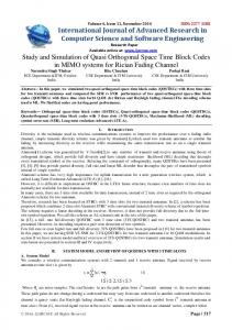
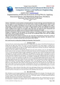
Fig. 4 Connect ion Diagram for MT8870 © 2014, IJARCSSE All Rights Reserved
Page | 813
Srivastava et al., International Journal of Advanced Research in Computer Science and Software Engineering 4(1), January - 2014, pp. 812-819 An MT8870 series DTMF decoder is used here. All types of the MT8870 series use digital counting techniques to detect and decode all the 16 DTMF tone pairs into a 4-bit code output. The built-in dial tone rejection circuit eliminates the need for pre-filtering. When the input signal given at pin 2 (IN-) in single-ended input configuration is recognized to be effective(see Fig. 4), the correct 4-bit decode signal of the DTMF tone is transferred to Q1 (pin 11) through Q4 (pin 14) outputs D0 through D3 outputs of the DTMF decoder (IC1) are connected to port pins of Microcontroller.
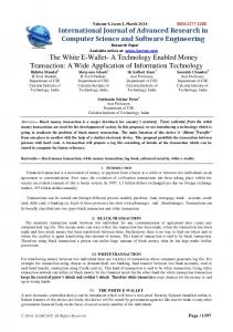
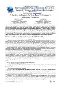
Fig. 4 Connect ion Diagram for MT8870 III. FRAMEWORK OF THE SYSTEM A. Block Diagram The heart of this robot is a Microcontroller, which is configured by programming in Embedded C language for 89S52 Microcontroller (see Fig. 5).
POWER SUPPLY UNIT
HUMIDITY SENSOR UNIT
DTMF DECODER UNIT
A D C
SMOKE SENSOR UNIT
0 8 0 8
METAL DETECTION UNIT
TEMPERATURE SENSOR UNIT
8-BIT DATA
8 9 S 5 2
RIGHT IR MODULE
MAX 232
GSM MODEM FOR SMS INTERFACING UNIT
L 2 9 3 D
OBSTACLE DETECTION UNIT LEFT IR MODULE
M1
M2
LCD 16 * 2
Fig. 5 Block Diagram
Sensor inputs as well as DTMF inputs are given to the microcontroller and hence microcontroller is programmed in such a way so that it will drive the motors according to the input as well as will send a SMS to the pre-defined cell phone number immediately after applying the power supply. Following is the flowchart of the whole system process flow (Fig. 6). © 2014, IJARCSSE All Rights Reserved
Page | 814
Srivastava et al., International Journal of Advanced Research in Computer Science and Software Engineering 4(1), January - 2014, pp. 812-819 START
TEMPERATURE & HUMIDITY MEASUREMENT
MICROCONTROLLER
LCD DIPLAY
DTMF SIGNAL
MICROCONTROLLER NO
2 PRESSED?
4 PRESSED?
No
Yes
MOVE FORWARD
OBSTACLE AHEAD?
No
8 PRESSED?
Yes
Yes
Yes
TURN LEFT
TURN RIGHT
MOVE BACK
SMOKE SENSED?
No
6 PRESSED?
No
METAL DETECTED?
No
Yes
Yes
MICROCONTROLLER PROCESSES
ADC CONVERTS TO DIGITA SIGNAL
MOTOR DRIVE
MICROCONTROLLER PROCESSES
CHANGE DIRECTION SEND A TEXT SMS TO PREDEFINED PHONE NUMBER
end
Fig. 6 Flowchart of the System The project uses CM-8870 DTMF decoder IC which decodes tone generated by the keypad of cell phone. When we press keys in our cell Phone when call is in progress, the other person will hear some tones with respect to keys pressed. These tones are based on the DTMF technology. Data is transmitted in terms of pair of tones. The receiver detects the valid frequency pair and gives the appropriate BCD code as the output of the DTMF decoder IC. DTMF signal can be tapped directly from the microphone pin of cell phone device. The following table instruction will be use to control robot direction. TABLE I Key
Direction
2 FORWARD 4 LEFT TURN 6 RIGHT TURN 8 BACKWARD © 2014, IJARCSSE All Rights Reserved
Page | 815
Srivastava et al., International Journal of Advanced Research in Computer Science and Software Engineering 4(1), January - 2014, pp. 812-819
Fig. 7 Overview of the Robotic Car B. Vehicle Movement Robot Chasis is the major platform of the Robot Vehicle, which is connected with a mobile using DTMF circuitry. A cell phone is connected to the vehicle through a 3.5mm audio jack(as shown in fig.), receives call from the calling subscriber and it will ask for a password from the caller. When the caller will enter the correct password, then only The DTMF decoder will activate and the H-bridge Module will begin functioning. According to the generated DTMF frequencies from the cell phone, the caller can control the robotic movement.
Fig. 8 Robot Chasis IC L293D is designed [6] in such a way to control two geared DC motors which takes command from the DTMF decoder through a Microcontroller. H-Bridge circuit is as shown in fig.9
Fig. 9 H-bridge circuit C. Metal Detector Unit This is a simple single chip metal detector circuit based on IC CS209A from the Cherry Semiconductors. A 100uH coil is used to sense the presence of metal. The IC CS209A has a built in oscillator circuit and the coil L1 forms a part of its external LC circuit which determines the frequency of oscillation. The inductance of the coil change in the presence of metals and the resultant change in oscillation is demodulated to create an alarm. The LED gives a visual indication too. This circuit can sense metals up to a distance of few inches. The circuit is shown below: © 2014, IJARCSSE All Rights Reserved
Page | 816
Srivastava et al., International Journal of Advanced Research in Computer Science and Software Engineering 4(1), January - 2014, pp. 812-819
Fig. 10 Metal Detector circuit D. Smoke Detector Unit The smoke detector is homebuilt using an IR emitter and detector. The voltage from the detector adjusts according to the amount of light being detected. This voltage is then compared to a reference voltage, high when the detector voltage is higher than the reference and low otherwise. The IR detector has an voltage output that reflects how much light it detects, around 2V with no obstructions and closer to 0V as less and less light is detected. Using this, the idea is to compare the voltage of the detector to a reference voltage that is calibrated such that if any of the light is obstructed from the detector, the voltage will drop below the reference voltage and the signal will go low. This low signal is then connected to INT1 on portD, thus allowing the smoke detector to externally interrupt the 89S52 and wake it up from sleep mode. Below is a circuit diagram of the smoke detector.
Fig. 11 Smoke Detector circuit E. Humidity Sensor unit This circuit is the typical astable design for 555. The HS1100/HS1101, used as variable capacitor, is connected to the TRIG and THRES pin. Pin 7 is used as a short circuit pin for resistor R4. The HS1100/HS1101 equivalent capacitor is charged through R2 and R4 to the threshold voltage (approximately 0.67Vcc) and discharged through R2 only to the trigger level (approximately 0.33Vcc) since R4 is shorten to ground by pin 7. R1 unbalances the internal temperature compensation scheme of the 555 in order to introduce a temperature coefficient that matches the HS1100/HS1101 temperature coefficient. In all cases, R1 should be a 1% resistor with a maximum of 100ppm coefficient temperature like all other R-C timer resistors. Since 555 internal temperature compensation changes from one trademark to one other, R1 value should be adapted to the specific chip. To keep the nominal frequency of 6660Hz at 55%RH, R2 also needs slight adjustment. © 2014, IJARCSSE All Rights Reserved
Page | 817
Srivastava et al., International Journal of Advanced Research in Computer Science and Software Engineering 4(1), January - 2014, pp. 812-819
Fig. 12 Humidity Sensor circuit F. Temperature Sensing unit The temperature sensor is LM335 wich has a linear characteristic of 10mV / K . In the production process this electronic device is calibrated so can provide 2.73V at 0°C. LM336 is used as a very precise 2.5V Zener diode; CA3040 amplification can be adjust between 1.08 and 1.10 times thru P1. This temperature measurement circuit can be used for Fahrenheit measurements, in this case the freezing point is adjusted with P1 at 32°F. At 212°F, P2 is adjusted to obtain 0.9V at output. So 1°F correspond to 5mV. For Celsius degrees the output voltage of IC2 is set with P1 at 2.73 V when the temperature of IC1 is 0°C. The calibration of the temperature indicator at 100°C is done by comparing it with a precision termometer. When LM335 is at this temperature adjust P2 so you read a 1 V difference at the output of the circuit.
Fig. 13 Temperature Sensor unit G. GSM based SMS interfacing unit In this unit, I have interfaced a GSM module with Microcontroller with programming in such a way so that it will send a SMS to the caller. In this scheme RTS and CTS signals of serial port interface of GSM Modem are connected with each other.The transmit signal of serial port of microcontroller is connected with transmit signal (TxD) of the serial interface of GSM Modem while receive signal of microcontroller serial port is connected with receive signal (RxD) of serial interface of GSM Modem. © 2014, IJARCSSE All Rights Reserved
Page | 818
Srivastava et al., International Journal of Advanced Research in Computer Science and Software Engineering 4(1), January - 2014, pp. 812-819 IV. SOFTWARE USED In this project, I have used Microsoft Visio software to design the Block diagram and flow chart. For programming of the Microcontroller, I have used Keil µVision4 software in Embedded C language and Python burner software for Microcontroller Program burning. V. APPLICATIONS AND FUTURE SCOPE A. Military use: Military usage of remotely controlled military vehicles dates back thefirst half of 20th century. This can be a great asset to save lives of both people along with soldiers in case of terrorist attacks like the one happened in 26 Nov, 2008 in Mumbai, India. B. Search and Rescue: Unmanned Aerial Vehicles (UAVs) will likely play an increased role in search and rescue in the United States. Slowly other European countries (even some developing nations) are thinking about making use of these vehicles in case of natural calamities & emergencies. C. Alarm Phone Dialer: By replacing DTMF Decoder IC CM8870 by a 'DTMF Transceiver IC CM8880, DTMF tones can be generated from the robot. So, a project called 'Alarm Phone Dialer' can be built which will generate necessary alarms for something that isdesired to be monitored (usually by triggering a relay). For example, a high water alarm, low temperature alarm, opening of back window, garage door, etc. D. Pick and Place arm: This robot can be modified by attaching a robotic arm which will pick and place the robot in the back carrier box [5]. In process of picking an object, one arm will be constant and other arm will move. This other arm grasps the object and picks it up. For this purpose motor of 100r.p.m, 30r.p.m will be use to control and move arm and it will work according to instruction it got from microcontroller through GSM (by operator). If yes then the arm will move 180 degree upwards and keep the object in carrier box. And this takes place with help of motor will move the robotic arm through a rod this all control and instruction are all under Microcontroller. VI. CONCLUSION By developing this robotic vehicle with its multi-tasking feature, I have overcome the drawbacks of RF communication which have a limited range whereas this car can be controlled from anywhere just using this DTMF technology. The main advantage of this robot is that it is password protected so that any other person cannot communicate with the robot. It has various sensors and a LCD screen in which the Humidity and Temperature of the place will be shown. sConsidering all the situations, the robot integrated with different sub modules can be used for redemption and security purpose. REFERENCES [1]. Lian, S.H., “Fuzzy Logic Control of an Obstacle Avoidance Robot”,IEEE International Conference of Fuzzy Systems, New Orleans, LA, September 8-1 1, 1996,vol.1,pp.26-30. [2]. Yen-Sheng chen, “Intelligent Obstacle Avoidance Control Strategy for Wheeled Mobile Robot”, ICROS-SICE International Joint Conference 2009 August 18-21, 2009, Fukuoka International Congress Center, Japan. [3]. Balasubramanian, K., “Object recognition and obstacle avoidance robot”, IEEE 17-19 June 2009 Chinese Control and Decision Conference (CCDC 2009). [4]. Dong-ying Ju, “Development of Remote Control and Monitor System for Autonomous Mobile Robot Based on Virtual Cell Phone”, IEEE 5-7 September 2007 Innovating Computing, Information and Control, 2007. ICICIC’07. Second International Conference. [5]. Manish Kumar., “Design of Cell Phone Operated Robot Using DTMF for Object Research”, IEEE Wireless and Optical Communications Networks (WOCN), 2013 Tenth International Conference on 26-28 July 2013. [6]. Mohammed M. Ali, “GPRS-Based Remote Sensing And Tele-operation Of A Mobile Robot”, IEEE 2013 10th International Multi-Conference on Signals, systems and devices, Hammarnet, Tunisia, March 18-21 2013.
© 2014, IJARCSSE All Rights Reserved
Page | 819